You also want an ePaper? Increase the reach of your titles
YUMPU automatically turns print PDFs into web optimized ePapers that Google loves.
<strong>Power</strong> <strong>Conditioning</strong> <strong>Unit</strong><br />
SPACE<br />
Based on the requirements for the ESA Rosetta deep<br />
space mission Terma has developed and qualified the<br />
<strong>Power</strong> <strong>Conditioning</strong> <strong>Unit</strong> (PCU) with the following<br />
special properties:<br />
• Regulated 28 volt, 2400 watt power bus<br />
• Maximum <strong>Power</strong> Point Tracking capability<br />
• Low mass of 8.3 kg<br />
• Autonomy redundancy of all functions<br />
• Very high power transfer efficiency<br />
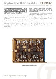
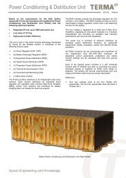
The unit is built in a new Terma developed power module<br />
technology allowing a power density up to 1kW / kg. It<br />
comprises the following module types:<br />
• (6) Array <strong>Power</strong> Regulation (APR)<br />
• (3) Battery Charge / Discharge Regulation (BCDR)<br />
• (2) Command and Monitoring (CM)<br />
• (1) Back plane module<br />
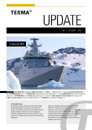
The PCU provides interfaces to two independent solar array<br />
sections. Each interface is formed by three APR modules<br />
operating in hot redundancy, providing full autonomy, single<br />
point failure free Maximum <strong>Power</strong> Point Tracker function. In<br />
addition the solar array voltage is due to this technique not<br />
directly linked to the main bus voltage and allows the PCU to<br />
fit a wide range of Solar Array configurations.<br />
The BCDR modules provides the charge and discharge<br />
regulation for three independent Li-Ion batteries, in single<br />
string configuration.<br />
For detailed ground monitoring the PCU provides a large<br />
number of analogue and digital telemetry that can be<br />
accessed through each of the two CM modules, operating in<br />
hot redundancy. All adjustable control parameters and<br />
protections can be uploaded and reset from ground control.<br />
The bus voltage is regulated by a voted set of Main Error<br />
Amplifiers, regulating all nine power modules in a 3-domain<br />
characteristic and providing an excellent load transient<br />
performance and very low bus impedance.<br />
Each of the applied power modules is a self contained<br />
function able to initialize and start up providing bus power<br />
whenever energy is available on either solar arrays or<br />
batteries. The system will recover autonomously from any<br />
single point failure without any bus power interruption.<br />
References:<br />
• One unit onboard Mars Express, flying since June 2003.<br />
• One unit onboard Rosetta, flying since March 2004.<br />
• One unit onboard Venus Express, flying since<br />
November 2005.<br />
Rosetta <strong>Power</strong> <strong>Conditioning</strong> <strong>Unit</strong> Flight Model<br />
Space Engineering and Knowledge
Specifications:<br />
Dimensions (L x W x H)<br />
267 x 238 x 158 [mm]<br />
Mass<br />
8.3 kg<br />
Reliability 11 years > 0.98<br />
Regulated bus voltage 28V ± 0.5%<br />
Output power capability<br />
up to 2400 watt<br />
Output impedance<br />
< 20 mΩ<br />
Bus voltage transient regulation < ± 1%<br />
Idle power consumption<br />
< 15 watt<br />
Solar array interface<br />
2 Sections each of 750 watt<br />
Maximum <strong>Power</strong> Point Tracking performance > 99.7%<br />
SA voltage range<br />
30V 80 volt<br />
Transfer efficiency > 95%<br />
Battery interface<br />
3 x Li-Ion<br />
Charge / Discharge power<br />
3 x 225 / 3 x 300 watt<br />
Transfer efficiency (charge / discharge) > 96% / > 94%<br />
DMS communication interface<br />
2 x ESA ML/TM Interface<br />
Solar Array<br />
30V - 80V<br />
SA Wing 2<br />
SA Wing 1<br />
3 x APR Section 2<br />
3 x APR Section 1<br />
APR 3<br />
APR 2<br />
APR 1<br />
Protection<br />
Protection<br />
Protection<br />
Local<br />
Aux<br />
Local<br />
Supply<br />
Aux<br />
Local<br />
Supply<br />
Aux<br />
Supply<br />
Array <strong>Power</strong><br />
Array Regulator <strong>Power</strong><br />
Array Regulator <strong>Power</strong><br />
Regulator<br />
Maximum <strong>Power</strong><br />
Maximum Point <strong>Power</strong> Tracker<br />
Maximum Point <strong>Power</strong> Tracker<br />
Point Tracker<br />
Bus<br />
Protection<br />
Bus<br />
Protection<br />
Bus<br />
Protection<br />
Dual<br />
CM I/F<br />
Dual<br />
CM I/F<br />
Dual<br />
CM I/F<br />
Backplane<br />
CS<br />
PDU #1<br />
Battery 3<br />
Battery 2<br />
Battery 1<br />
Lithium Ion<br />
Batteries<br />
16V - 25V<br />
DMS ML/TM<br />
BCDR 3<br />
BCDR 2<br />
BCDR 1<br />
Battery<br />
Protection<br />
Battery<br />
Battery<br />
Protection<br />
Protection<br />
Local<br />
Aux<br />
Local<br />
Supply<br />
Local<br />
Aux<br />
Aux<br />
Supply<br />
Supply<br />
CM I/F B<br />
CM I/F A<br />
ML/TM<br />
I/F<br />
ML/TM<br />
I/F<br />
Solar Array<br />
Performance<br />
Solar Array<br />
Monitor<br />
Performance<br />
Monitor<br />
Battery Charge<br />
Battery Regulator Charge<br />
Battery Regulator Charge<br />
Regulator<br />
Battery Discharge<br />
Battery Regulator Discharge<br />
Battery Regulator Discharge<br />
Regulator<br />
Command & Telemetry<br />
Command Handling & Telemetry<br />
Handling<br />
Battery<br />
Discharge<br />
Battery<br />
Alarm<br />
Discharge<br />
Alarm<br />
Main Bus<br />
Reconnect<br />
Main Bus<br />
Reconnect<br />
Bus<br />
Protection<br />
Bus<br />
Protection<br />
Bus<br />
Protection<br />
Dual<br />
CM I/F<br />
Dual<br />
CM I/F<br />
Dual<br />
CM I/F<br />
Local<br />
Aux<br />
Local<br />
Supply<br />
Aux<br />
Supply<br />
DUAL CM INTERFACE BUS<br />
Voted MEA Regulation<br />
MEA 3<br />
MEA 2<br />
MEA 1Vo-<br />
E/A<br />
Vo-tinting<br />
E/A<br />
E/A<br />
Voting<br />
DISTR<br />
BUS<br />
CAP.<br />
Regulated 28V <strong>Power</strong> Bus<br />
CS<br />
28V ±0.5%<br />
Zo < 20mΩ<br />
PDU #2<br />
Rosetta <strong>Power</strong> <strong>Conditioning</strong> <strong>Unit</strong> Functional Schematic<br />
Terma A/S Space<br />
www.<strong>terma</strong>.com