Technical Note No.6 Trench Lining Systems - Design ... - Groundforce
Technical Note No.6 Trench Lining Systems - Design ... - Groundforce
Technical Note No.6 Trench Lining Systems - Design ... - Groundforce

You also want an ePaper? Increase the reach of your titles
YUMPU automatically turns print PDFs into web optimized ePapers that Google loves.
<strong>Technical</strong> <strong>Note</strong> <strong>No.6</strong><br />
<strong>Trench</strong> <strong>Lining</strong> <strong>Systems</strong> - <strong>Design</strong> Statement<br />
<strong>Trench</strong> Boxes<br />
<strong>Groundforce</strong> Shorco supplied trench boxes have been designed (in accordance with BS EN 13331-<br />
1: 2002) to support the worst ground conditions that can reasonably be expected to be encountered<br />
within the dimensional capabilities of the panels, including the upper panels. It is therefore not<br />
normally necessary to carry out site-specific soil pressure calculations. Exceptions to this<br />
however are in high surcharge applications, the proximity of sensitive structures, deep (greater than<br />
4m) excavations in very poor ground e.g. very soft clays and wide (greater than 3m) trenches.<br />
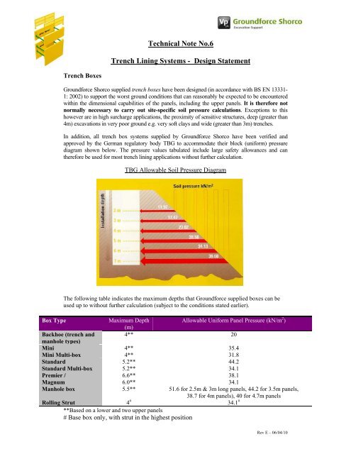
In addition, all trench box systems supplied by <strong>Groundforce</strong> Shorco have been verified and<br />
approved by the German regulatory body TBG to accommodate their block (uniform) pressure<br />
diagram shown below. The pressure values tabulated include large safety allowances and can<br />
therefore be used for most trench lining applications without further calculation.<br />
TBG Allowable Soil Pressure Diagram<br />
The following table indicates the maximum depths that <strong>Groundforce</strong> supplied boxes can be<br />
used up to without further calculation (subject to the conditions stated earlier).<br />
Box Type<br />
Maximum Depth<br />
Allowable Uniform Panel Pressure (kN/m 2 )<br />
(m)<br />
Backhoe (trench and<br />
4** 20<br />
manhole types)<br />
Mini<br />
Mini Multi-box<br />
4**<br />
4**<br />
35.4<br />
31.8<br />
Standard<br />
Standard Multi-box<br />
5.2**<br />
5.2**<br />
44.2<br />
34.1<br />
Premier /<br />
Magnum<br />
6.6**<br />
6.0**<br />
38.1<br />
34.1<br />
Manhole box 5.5** 51.6 for 2.5m & 3m long panels, 44.2 for 3.5m panels,<br />
38.7 for 4m panels), 40 for 4.7m panels<br />
Rolling Strut 4 # 34.1 #<br />
**Based on a lower and two upper panels<br />
# Base box only, with strut in the highest position<br />
Rev E – 06/04/10
<strong>Note</strong> that the allowable pressures at the maximum stated depths comfortably exceed the TBG<br />
pressure requirements.<br />
As a further guide for the selection of the best system, the tractive forces required to extract<br />
boxes can be considerable. The following table can be used as a guide for excavator sizing.<br />
<strong>Trench</strong> Box Extraction Forces<br />
Where the end wall of a trench requires support it is essential that no<br />
lateral load is applied to the box struts. Purpose made end closure panels<br />
are available for closing off the ends of boxes if required. Any contractor<br />
designed end support members must thrust off the ends of the box panels.<br />
The structural adequacy and integrity of non-standard end support<br />
members is the responsibility of the contractor.<br />
<strong>Note</strong>: <strong>Groundforce</strong> does not recommend the practice of “flying” trench boxes above the base<br />
of the excavation as this can potentially overload the lower struts.<br />
Drag Boxes<br />
Drag boxes as their name suggests are intended to be pulled or<br />
dragged through the excavation as the work proceeds. They are<br />
therefore designed to be used in pre-dominantly stable ground<br />
conditions in battered excavations.<br />
They therefore act as shields to protect the workforce rather that<br />
provide positive ground support as in the case of a trench box.<br />
Drag box plates do have a working load capacity commensurate<br />
with their height and would evidently provide support in the case of ground movement.<br />
However it is not industry policy to provide site-specific designs with this equipment<br />
type. Any assessment for the use of drag boxes should be carried out at site level where first<br />
hand knowledge of ground conditions and hence short-term ground stability is available.<br />
Rev E – 06/04/10
Chain attachment points on boxes<br />
All boxes are equipped with two types of chain attachment points.<br />
Handling points as the name suggests are provided at various locations around<br />
the box panels to enable them to be slung for assembly purposes in both<br />
horizontal and vertical planes.<br />
Lifting points are much heavier duty constructions designed to take the full weight<br />
of the box including extraction forces when pulling them out of the ground. These<br />
points are located in the top of the box panels and are denoted by red paint.<br />
<strong>Note</strong>s:<br />
1. Lifting points can be used for handling purposes but handling points must<br />
not be used for lifting assembled boxes.<br />
2. Chain attachment points have been designed in accordance with BS EN 13331-1:<br />
2002. clause 7.4.<br />
3. No separate certification is required for these points under LOLER<br />
MAP system boxes<br />
The modular aluminium panel box system is a lightweight yet high strength<br />
box system that can be assembled by hand and lifted and handled by backhoe<br />
type excavators. Using just three main components - panels, struts, and corner<br />
posts, the system provides great versatility by allowing 2, 3, and 4 sided<br />
support as the job demands. <strong>Note</strong> that MAP boxes do not fall within the scope<br />
of BS EN 13331-1:2002<br />
MAP Panel Length Maximum<br />
Depth (m)<br />
Allowable Uniform Panel<br />
Pressure (kN/m 2 )#<br />
990mm 4.8* 100.0<br />
1600mm 4.8* 60.0<br />
* Panels are 600mm high, posts are either 1200mm or 1800mm high.<br />
# assuming two struts per individual post<br />
Installation<br />
Installation and on-going inspection must be under the supervision of a competent person.<br />
User guides are available for all equipment referred to in this document.<br />
<strong>Note</strong>: A toolbox talk DVD is available for box installations. Ring 0800 000 345 for<br />
details.<br />
Rev E – 06/04/10