57007B - Pro Comp USA
57007B - Pro Comp USA
57007B - Pro Comp USA

Create successful ePaper yourself
Turn your PDF publications into a flip-book with our unique Google optimized e-Paper software.
2360 Boswell Road<br />
Chula Vista, CA 91914<br />
Phone 619.216.1444<br />
Fax 619.216.1474<br />
E-Mail tech@explorerprocomp.com<br />
PRO COMP SUSPENSION<br />
Suspension Systems that Work!<br />
IMPORTANT!: 18” OR LARGER WHEELS WITH 4 3/4” OF<br />
MAXIMUM BACKSPACING MUST BE USED IN CONJUNC-<br />
TION WITH THIS LIFT KIT! See pg. 7 for details.<br />
Part #57007/57007MX<br />
2006-2007<br />
TOYOTA FJ<br />
4WD/2WD<br />
This document contains very important information that includes warranty information and instructions for<br />
resolving problems you may encounter. Please keep it in the vehicle as a permanent record.
57007/57007MX<br />
Revised<br />
3.12.07<br />
Box 1 of 5-PN 57007/57008MX-1<br />
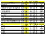
Part # Description Qty. Illus. Page<br />
90-3648 FRONT CROSSMEMBER 1 3,6,7 10,12<br />
90-3652 FRONT CROSSMEMBER NUT PLATE 2 3 10<br />
90-6502 HARDWARE PACK: Front Crossmember 1 - -<br />
70-0501001800 1/2” X 1 1/4” GR. 8 HEX BOLT 2 3 10<br />
73-0500083 1/2” SAE GR. 8 FLAT WASHER 8 3 10<br />
90-6440 HARDWARE PACK: Differential 1 - -<br />
70-0503251800 1/2” x 3 3/4” GR. 8 HEX BOLT 1 6 12<br />
70-0504001800 1/2” x 4” GR. 8 HEX BOLT 3 6,7 12<br />
72-050100816 1/2” GR. 8 STOVER NUT 4 6,7 12<br />
73-0500083 1/2” SAE GR. 8 FLAT WASHER 8 6,7 12<br />
71-120901501000 12mm-1.5 X 90mm GR. 10.9 HEX BOLT 1 4 11<br />
72-12150816 12mm-1.5 NYLOCK NUT 1 4 11<br />
73-01208840 12mm FLAT WASHER 2 4 11<br />
73-01400834 14mm HARDENED FLAT WASHER 2 4 11<br />
71-140401501000 14mm-1.5 X 30mm HEX BOLT 10.9 2 4 11<br />
90-3654 FRONT BUMP STOP- Driver 1 14 17<br />
90-3657 FRONT BUMP STOP- Passenger 1 - -<br />
90-6441 HARDWARE PACK: Bump Stop 1 - -<br />
71-100301251000 10mm-1.25 X 30mm GR. 10.9 HEX BOLT 2 14 17<br />
72-10125816 10mm-1.25 STOVER NUT 2 14 17<br />
73-01008840 10mm FLAT WASHER 4 14 17<br />
90-6506 HARDWARE PACK: Tacoma Diff Bushings 1 - -<br />
90-2533 DIFFERENTIAL SLEEVE SHORT 1 4 11<br />
90-2109 DIFFERENTIAL SLEEVE LONG 3 4 11<br />
90-2629 DIFFERENTIAL SPACER SHORT 1 4 11<br />
90-2630 DIFFERENTIAL SPACER LONG 1 4 11<br />
15-11148 COMPRESSION STRUT BUSHING 8 4 11<br />
90-6507 HARDWARE PACK: Front Brake Line 1 - -<br />
90-55089-4 FRONT BRAKE LINE EXTENSION- Drvr 1 - -<br />
90-55089-3 FRONT BRAKE LINE EXTENSION- Pass 1 - -<br />
90-3659 DIFF VENT RELOCATION EXTENSION 1 10 14<br />
90-3660 REAR BRAKE LINE EXTENSION BRACKET 1 25 24<br />
90-6299 HARDWARE PACK: E–Brake Line/Brake Line/ABS Line 2 - -<br />
70-0311001500 5/16” X 1” GR.5 HEX BOLT 2 10,25 14,24<br />
72-03100100512 5/16” NYLOCK NUT 2 10,25 14,24<br />
73-03100030 5/16” SAE FLAT WASHER 4 10,25 14,24<br />
90-2537 COMPRESSION STRUTS 2 19 20<br />
90-6263 HARDWARE PACK: Bushings and Sleeves 1 - -<br />
15-11148 COMPRESSION STRUT BUSHING 8 19 20<br />
90-2109 SLEEVE; COMPRESSION STRUT - 2.75” 4 19 20<br />
90-6234 HARDWARE PACK: <strong>Comp</strong>ression Struts 1 - -<br />
70-0501251800 1/2" X 1 1/4" GR 8 HEX BOLT 2 19 20<br />
70-0504001800 1/2" X 4" GR 8 HEX BOLT 4 19 20<br />
72-050100816 1/2" GR 8 STOVER NUT 4 19 20<br />
73-05000034 1/2" SAE HARDENED FLAT WASHER 10 19 20<br />
2
57007/57007MX<br />
Revised<br />
3.12.07<br />
Part # Description Qty. Illus. Page<br />
90-1435 COMPRESSION STRUT MOUNTS 2 19 20<br />
90-3353 COMPRESSION STRUT NUT PLATE 2 19 20<br />
90-3887 FRONT SWAY BAR DROP BRACKET 2 15 18<br />
90-6223 HARDWARE PACK: Sway Bar 1 - -<br />
70-0371251800 3/8” X 1 1/4" GRADE 8 HEXBOLT 4 15 18<br />
72-037100816 3/8" USS STOVER NUT 4 15 18<br />
73-03700034 3/8" SAE GRADE 8 WASHER 8 15 18<br />
90-4134 REAR DRIVESHAFT SPACER 1 - -<br />
90-6509 HARDWARE PACK: Driveshaft 1 - -<br />
.100F650HCS1Y 10mm-1.5 X 65mm 10.9 HEX BOLT 4 - -<br />
72-10150816 10mm–1.5 NYLOCK NUT 4 - -<br />
73-01200830 10mm SAE FLAT WASHER 8 - -<br />
Box 2 of 5-PN 57007/57008MX-2<br />
90-4144 STEERING KNUCKLE– Driver 1 - -<br />
90-4145 STEERING KNUCKLE– Passenger 1 - -<br />
90-6452 HARDWARE PACK: Knuckle 1 - -<br />
70-0622001800 5/8”X 2” Gr. 8 HEX BOLT 4 - -<br />
73-06200838 5/8” A.N. FLAT WASHER 4 - -<br />
90-6453 HARDWARE PACK: Bump Stop 1 - -<br />
70-0622001800 ADEL CLAMP (w/ 10mm hole) 2 - -<br />
90-6454 HARDWARE PACK: Weld On Knuckle Steering Stop 1 - -<br />
90-3399 KNUCKLE STEERING STOP EXTENSION - Driver 1 13 16<br />
90-3400 KNUCKLE STEERING STOP EXTENSION - Pass 1 13 16<br />
90-6571 HARDWARE PACK: Weld On A-Arm Steering Stop 1 - -<br />
96-3888 A-ARM STEERING STOP EXTENSION 2 13 16<br />
Box 3 of 5-PN 57007/57008MX-3<br />
90-3661 REAR CROSSMEMBER 1 1,2,8,9 9,13<br />
90-6445 HARDWARE PACK: Nut Plate 1 - -<br />
70-0371001800 3/8” X 1” GR. 8 HEX BOLT 3 9 13<br />
73-0370083 3/8” SAE GR. 8 FLAT WASHER 3 9 13<br />
90-3342 REAR CROSSMEMBER NUT PLATE 1 9 13<br />
90-3346 DIFFERENTIAL MOUNT– Driver Rear 1 4 11<br />
90-3348 DIFFERENTIAL MOUNT– Driver Front 1 4 11<br />
90-3350 DIFFERENTIAL MOUNT– Passenger 1 4 11<br />
90-6314 HARDWARE PACK: Diff Vent/Bump Stop 1 - -<br />
70-0311001800 5/16” X 1” HEX BOLT GR. 8 1 10 14<br />
72-031100816 5/16” STOVER NUT 1 10 14<br />
73-03100838 5/16” USS FLAT WASHER 2 10 14<br />
3
4<br />
57007/57007MX<br />
Revised<br />
3.12.07<br />
Part # Description Qty. Illus. Page<br />
70-0371501800 3/8” X 1 1/2” HEX BOLT GR. 8 2 14 17<br />
72-037100816 3/8” STOVER NUT GR. 8 2 14 17<br />
73-03700034 3/8” HARDENED FLAT WASHER 4 14 17<br />
90-6444 HARDWARE PACK: Crossmembers 1 - -<br />
70-0755001800 3/4” X 5” GR. 8 HEX BOLT 2 3 10<br />
72-075100816 3/4” GR. 8 STOVER NUT 2 3 10<br />
73-0750083 3/4” SAE GR. 8 FLAT WASHER 4 3 10<br />
70-0501501800 1/2” X 1 1/2” GR.8 HEX BOLT 1 1 9<br />
70-0505501800 1/2” X 5 1/2” GR. 8 HEX BOLT 2 1 9<br />
72-050100816 1/2” GR. 8 STOVER NUT 2 1 9<br />
73-0500083 1/2” SAE GR. 8 FLAT WASHER 5 1 9<br />
90-6447 HARDWARE PACK: Block Off Plates 1 - -<br />
90-3344 CAM BLOCK OFF PLATES- Small Hole 4 1 9<br />
90-3345 CAM BLOCK OFF PLATES- Large Hole 4 3 10<br />
90-3665 REAR BUMP STOP- Driver 1 24 24<br />
90-3668 REAR BUMP STOP- Passenger 1 - -<br />
90-2631 REAR SWAY BAR END LINKS 2 20 22<br />
90-6508 HARDWARE PACK: Rear Sway Bar 1 - -<br />
72-037200510 3/8” SAE GR. 5 HEX NUT 2 20 22<br />
600056 3/8” STEM CUSHION SOFT 4 20 22<br />
060408 RET. WASHER 4 20 22<br />
600006 BUSHING 2 20 22<br />
54314 SLEEVE 2 20 22<br />
90-3674 REAR TRACK BAR RELOCATION BRACKET 1 23 23<br />
90-6511 HARDWARE PACK: Rear Track Bar Bracket 1 - -<br />
90-3678 SPACER PLATE: Track Bar Bracket 1 23 23<br />
70-0501251800 1/2” X 1 1/4” GR. 8 HEX BOLT 1 23 23<br />
73-0500083 1/2” SAE FLAT WASHER 1 23 23<br />
70-0563501800 9/16" X 3 1/2" GR. 8 HEX BOLT 1 26 25<br />
72-056100816 9/16" GR. 8 STOVER 1 26 25<br />
73-05600034 9/16" SAE FLAT WASHER 2 26 25<br />
90-3679 NUT PLATE: Track Bar Bracket 1 23 23<br />
90-2634 REAR UPPER CONTROL ARM 2 22 23<br />
90-6512 HARDWARE PACK: Rear Upper Control Arms 1 - -<br />
90-2637 REAR CONTROL ARM SLEEVE 4 22 23<br />
15-11190 BUSHINGS 8 22 23<br />
90-6299 HARDWARE PACK: Rear Bump Stop 2 - -<br />
70-0311001500 5/16” X 1” GR.5 HEX BOLT 2 10,24 14,24<br />
72-03100100512 5/16” NYLOCK NUT 2 10,24 14,24<br />
73-03100030 5/16” SAE FLAT WASHER 4 10,24 14,24<br />
90-6283 HARDWARE PACK: Rear Shock Spacer 1 - -<br />
73-05000030 1/2” SAE FLAT WASHER 4 20 22<br />
72-05000100512 1/2” NYLOCK NUT 2 20 22<br />
70-0502751800 1/2” X 2 3/4” GR. HEX BOLT 2 20 22
57007/57007MX<br />
Revised<br />
3.12.07<br />
Part # Description Qty. Illus. Page<br />
Box 4 of 5-PN 57007/57008MX-4<br />
57470-1 REAR COIL SPRING 2 - -<br />
Box 5 of 5-PN 57007-5<br />
ES9024 ES SERIES REAR SHOCK 2 - -<br />
90-6317 HARDWARE PACK: Spacer Mount 1 - -<br />
72-043200810 7/16” GR. 8 PLATED HEX NUT 6 11a,11b,12 15<br />
73-04300830 7/16” SAE FLATWASHER 6 11a,11b,12 15<br />
73-04300836 7/16” LOCK WASHER 6 11a,11b,12 15<br />
6300.01 URETHANE SPRING ISOLATOR 2 11a 15<br />
90-3398 3/8” COIL SPRING SPACER 2 11a 15<br />
90-2539 STRUT SPACER 2 11b 15<br />
90-6510 HARDWARE PACK: Rear Shock Relocation Bracket 1 - -<br />
90-3682 LOWER SHOCK MOUNT 2 21 22<br />
90-6283 HARDWARE PACK: Rear Shock Spacer 1 - -<br />
73-05000030 1/2” SAE FLAT WASHER 4 21 22<br />
72-05000100512 1/2” NYLOCK NUT 2 21 22<br />
70-0502751800 1/2” X 2 3/4” GR. HEX BOLT 2 21 22<br />
OR Box 5MX of 6-PN 57008MX-5<br />
626001 COIL OVER 1 11b,12 15<br />
90-6450 HARDWARE PACK: Coil over mounting spacers 1 - -<br />
90-2433 UPPER SPACERS 4 12 15<br />
90-2550 LOWER SPACERS 4 12 15<br />
90-3391 COIL OVER MOUNT: Upper Bracket 1 12 15<br />
MX6024 MX6 SHOCKS 1 - -<br />
90-6317 HARDWARE PACK: Spacer Mount 1 - -<br />
72-043200810 7/16” GR. 8 PLATED HEX NUT 6 11b,12 15<br />
73-04300830 7/16” SAE FLATWASHER 6 11b,12 15<br />
73-04300836 7/16” LOCK WASHER 6 11b,12 15<br />
90-3396 COIL OVER SPACER- DRVR: Upper Bracket 1 12 15<br />
90-6510 HARDWARE PACK: Rear Shock Relocation Bracket 1 - -<br />
90-3682 LOWER SHOCK MOUNT 2 21 22<br />
90-6283 HARDWARE PACK: Rear Shock Spacer 1 - -<br />
73-05000030 1/2” SAE FLAT WASHER 4 21 22<br />
72-05000100512 1/2” NYLOCK NUT 2 21 22<br />
70-0502751800 1/2” X 2 3/4” GR. HEX BOLT 2 21 22<br />
Box 6MX of 6-PN 57008MX6<br />
626001 COIL OVER 1 11b,12 15<br />
90-3010 COIL OVER WRENCH: Large 1 - -<br />
5
57007/57007MX<br />
Revised<br />
3.12.07<br />
Part # Description Qty. Illus. Page<br />
90-3011 COIL OVER WRENCH: Small 1 - -<br />
90-6318 HARDWARE PACK: Coil Over Mount 1 - -<br />
70-0502751800 1/2" X 2 3/4" HEX BOLT 2 12 15<br />
73-05000830 1/2" SAE FLAT WASHER 4 11b,12 15<br />
72-050100816 1/2” STOVER NUT 2 11b,12 15<br />
90-3391 COIL OVER MOUNT: Upper Bracket 1 21 22<br />
MX6024 MX6 SHOCKS 1 21 22<br />
♦<br />
♦<br />
♦<br />
♦<br />
♦<br />
♦<br />
♦<br />
♦<br />
♦<br />
♦<br />
♦<br />
Introduction:<br />
This installation requires a professional mechanic!<br />
We recommend that you have access to a factory service manual for your vehicle to assist in the<br />
disassembly and reassembly of your vehicle. It contains a wealth of detailed information.<br />
Prior to installation, carefully inspect the vehicle’s steering and driveline systems paying close attention<br />
to the tie rod ends, ball joints, wheel bearing preload, pitman and idler arm. Additionally,<br />
check steering-to-frame and suspension-to-frame attaching points for stress cracks. The overall<br />
vehicle must be in excellent working condition. Repair or replace all worn or damaged parts!<br />
Read the instructions carefully and study the illustrations before attempting installation! You may<br />
save yourself a lot of extra work.<br />
Check the parts and hardware against the parts list to assure that your kit is complete. Separating<br />
parts according to the areas where they will be used and placing the hardware with the brackets<br />
before you begin will save installation time.<br />
Check the special equipment list and ensure the availability of these tools.<br />
Secure and properly block vehicle prior to beginning installation.<br />
ALWAYS wear safety glasses when using power tools or working under the vehicle!<br />
Use caution when cutting is required under the vehicle. The factory undercoating is flammable.<br />
Take appropriate precautions. Have a fire extinguisher close at hand.<br />
Foot pound torque readings are listed on the Torque Specifications chart at the end of the instructions.<br />
These are to be used unless specifically directed otherwise. Apply thread lock retaining<br />
compound where specified.<br />
Please note that while every effort is made to ensure that the installation of<br />
your <strong>Pro</strong> <strong>Comp</strong> lift kit is a positive experience, variations in construction and<br />
assembly in the vehicle manufacturing process will virtually ensure that<br />
some parts may seem difficult to install. Additionally, the current trend in<br />
manufacturing of vehicles results in a frame that is highly flexible and may<br />
shift slightly on disassembly prior to installation. The use of pry bars and tapered<br />
punches for alignment is considered normal and usually does not indicate<br />
a faulty product. However, if you are uncertain about some aspect of the<br />
installation process, please feel free to call our tech support department at<br />
the number listed on the cover page. We do not recommend that you modify<br />
the <strong>Pro</strong> <strong>Comp</strong> parts in any way as this will void any warranty expressed or<br />
implied by the <strong>Pro</strong> <strong>Comp</strong> Suspension company.<br />
6
Important!<br />
Please Note:<br />
∗ Front suspension and head light realignment is necessary!<br />
57007/57007MX<br />
Revised<br />
3.12.07<br />
Tire and wheel choice is crucial in assuring proper fit, performance,<br />
and the safety of your <strong>Pro</strong> <strong>Comp</strong> equipped vehicle. For this application, we<br />
recommend an 18” X 8” wheel with a maximum backspacing of 4 3/4”.<br />
Additionally, a quality tire of radial design, not exceeding 35” tall X 12.5”<br />
wide is recommended. Please note that the use of a 35” X 12.5” tire may<br />
require fender modification. Installation of larger wheels may be possible.<br />
Be sure to check fit all wheel and tire combinations before purchasing and<br />
installation. Violation of these recommendations will not be endorsed as<br />
acceptable by <strong>Pro</strong> <strong>Comp</strong> Suspension and will void any and all warranties<br />
either written or implied.<br />
IMPORTANT!: 18” OR LARGER WHEELS MUST BE<br />
USED IN CONJUNCTION WITH THIS LIFT KIT!<br />
∗ Speedometer and ABS recalibration will be necessary if larger tires (10% more than<br />
stock diameter) are installed.<br />
∗ Always use NEW cotter pins on re-assembly! (These items are NOT supplied)<br />
∗ IT IS ADVISABLE THAT YOU HAVE HELP AVAILABLE WHEN INSTALLING<br />
THIS KIT. SOME COMPONENTS ARE HEAVY AND AWKWARD. ADDI-<br />
TIONAL HELP IS GOOD INSURANCE AGAINST INJURY!<br />
Special Tools:<br />
Please refer to your service manual for more information.<br />
A special removal tool is required for safe removal of the tie rods.<br />
These tools may be purchased at your local Toyota dealer.<br />
You may be able to rent any of these tools at your local parts store.<br />
Optional Equipment Available from your <strong>Pro</strong> <strong>Comp</strong><br />
Distributor!<br />
Coil Over Upgrade Kit: 57008<br />
Also, Check out our outstanding selection of<br />
installation!<br />
tires to compliment your new<br />
7
Front Installation:<br />
1. Prior to installing this kit, with the vehicle on<br />
the ground. Measure the height of your vehicle.<br />
This measurement can be recorded from<br />
the center of the wheel, straight up to the top<br />
of the inner fender lip. Record the measurements<br />
below.<br />
LF:<br />
LR:<br />
For 2WD installation skip steps 17-26, 29-33, 35, 43, 81.<br />
RF:<br />
RR:<br />
2. Ensure that your work space is of adequate<br />
size and the work surface is level. Place the<br />
vehicle in park. Disconnect the negative battery<br />
cable from the battery. Place your floor<br />
jack under the front cross member and raise<br />
vehicle. Place jack stands under the frame<br />
rails behind the front wheel wells and lower<br />
the frame onto the stands. Remove the jack<br />
and place the vehicle back in gear, set the<br />
emergency brake, and place blocks both in<br />
front of and behind the rear wheels. Remove<br />
the front wheels.<br />
3. Remove the skid plate and the skid plate support<br />
brackets.<br />
4. If the vehicle is equipped with factory frame<br />
support bars, that connect the transmission<br />
crossmember to the inside of the frame rails,<br />
remove the bars from the vehicle.<br />
5. Un clip the ABS line from the knuckle, unbolt<br />
the anti-lock wiring and sensor from the<br />
hub and the brake line from the rear of the<br />
knuckle.<br />
6. Using the appropriate tool, remove the outer<br />
tie rod end nut and separate from the knuckle.<br />
7. Unbolt the sway bar end links and remove<br />
them from the vehicle. Unbolt the sway bar<br />
frame mount brackets and remove the sway<br />
bar. Save the parts and hardware for reuse.<br />
8. Work on one side of the vehicle at a time.<br />
9. Remove the brake caliper from the rotor and<br />
57007/57007MX<br />
Revised<br />
3.12.07<br />
secure them clear from the work area. DO<br />
NOT let the caliper hang by the brake line or<br />
damage may result.<br />
10. Remove the front rotors from the front hub.<br />
11. Remove the dust cap and the axle retaining<br />
nut.<br />
12. Unbolt the (4) bolts holding the hub flange to<br />
the knuckle and remove the hub. Save for<br />
reinstallation.<br />
NOTE: You will not be able to remove<br />
the bolts from the hub assembly after the hub is<br />
removed from the knuckle.<br />
13. Support the knuckle and remove the upper<br />
ball joint nut from the knuckle and separate<br />
using the appropriate tool.<br />
14. Remove the (2) bolts from the lower ball joint<br />
bracket. Remove the knuckle from the vehicle.<br />
15. Unbolt and remove the factory coil over assembly<br />
from the vehicle. Save the hardware<br />
for reuse.<br />
16. Remove the lower A-arm from the vehicle.<br />
NOTE: Be sure to support the CV axles<br />
before removing the lower A-arm. DO NOT allow<br />
the axles to hyperextend or damage to the<br />
bearings might result.<br />
17. Repeat steps 9 through 16 on the remaining<br />
side of the vehicle.<br />
IMPORTANT!: Cutting the frame is not necessary<br />
for 2WD installation of this kit.<br />
18. Unbolt the front driveshaft from the differential.<br />
Secure the driveshaft up and out of the<br />
work area.<br />
19. Unclip all electrical wiring, vacuum lines and<br />
vent lines from the differential. Unbolt and<br />
remove all the diff harness brackets from the<br />
engine block.<br />
8
57007/57007MX<br />
Revised<br />
3.12.07<br />
Cam<br />
Block<br />
Off<br />
Plate<br />
90-3344 Cam Block<br />
Off Plate 90-3344<br />
1/2”<br />
X 5<br />
1/2”<br />
Bolt<br />
Illustration 1<br />
Rear Crossmember<br />
Installation<br />
Rear Crossmember<br />
90-3661<br />
Frame<br />
Rail<br />
Edge of Lower Control Arm weld<br />
Illustration 2a<br />
Frame Cut Guide<br />
Approx. 6 3/4”<br />
Frame<br />
4 3/4”<br />
Measure<br />
4 3/4”<br />
from the<br />
inside of<br />
the frame<br />
rail<br />
Outer<br />
Cut Line<br />
Inner<br />
Cut Line<br />
90-3661 Rear Crossmember<br />
IMPORTANT: IT IS<br />
NOT NECESSARY TO<br />
CUT FRAME FOR<br />
2WD KIT<br />
INSTALLATION<br />
Illustration 2b<br />
Frame Cut Away<br />
Frame<br />
Cut Piece<br />
9
57007/57007MX<br />
Revised<br />
3.12.07<br />
Illustration 3<br />
Front Crossmember<br />
Installation<br />
Cam Block<br />
Off Plate<br />
90-3345 Front<br />
Crossmember<br />
90-3648<br />
3/4 X<br />
5” Bolt<br />
Nut Plate 90-3652<br />
1/2 X 1<br />
1/4” Bolt<br />
20. Support the differential with a jack and unbolt<br />
the rear mount differential mount.<br />
21. Remove the (2) front differential mount bolts<br />
from the front crossmember. Remove the<br />
differential from the vehicle.<br />
22. Raise the rear crossmember (90-3361) into<br />
the rear frame mounting pockets and hang in<br />
place using the supplied 1/2” X 5 1/2” bolts<br />
and small hole cam block off plates (90-<br />
3344). See ILLUSTRATION 1.<br />
NOTE: Due to variations in frame tolerances<br />
from the factory, the holes in the cam<br />
block off plates are offset to provide adjustability.<br />
If the bolt holes do not line up with the cam<br />
block off plate notches facing down they can be<br />
rotated to aid installation of the cam bolts. In<br />
order for the crossmember to stay centered in<br />
the vehicle the notches in the cam block off<br />
plates must be facing the same way on both<br />
driver and passenger sides. Ex. Both notches<br />
facing up, down, in or out.<br />
23. Use the rear crossmember (90-3661) as a<br />
template for marking the frame for cutting.<br />
24. Use the driver side edge of the rear crossmember<br />
lip to mark the frame for the inside<br />
edge of the cut. See ILLUSTRATION 2a.<br />
25. Measure in 4 3/4” from the inside of the<br />
driver side frame rail. Make sure the measurement<br />
is square and mark a line around the<br />
Nut Plate Install<br />
10<br />
1/2X<br />
1 1/4”<br />
Bolt<br />
frame for the outer edge of the cut. See IL-<br />
LUSTRATION 2a.<br />
NOTE: Be sure that the outer cut line is<br />
at least an 1/8” to 1/4” from the bottom of the<br />
rear lower control arm pocket welds.<br />
26. Remove the rear crossmember to allow access<br />
for cutting the frame.<br />
27. Using a suitable cutting tool, (abrasive cutoff<br />
wheel, Sawz-all, etc.) cut the frame along the<br />
previously marked lines as shown in ILLUS-<br />
TRATION 2a. After cutting the section out<br />
of the frame, clean the area thoroughly and<br />
paint the exposed metal with a good quality<br />
paint.<br />
28. Install the front crossmember (90-3648) into<br />
the front mounting pockets using the supplied<br />
3/4” X 5” bolts and cam block off plates (90-<br />
3345). Install the cam block off plates with<br />
the notches facing down. See ILLUSTRA-<br />
TION 3.<br />
NOTE: Due to variations in frame tolerances<br />
from the factory, the holes in the cam<br />
block off plates are offset to provide adjustability.<br />
If the bolt holes do not line up with the cam<br />
block off plate notches facing down they can be<br />
rotated to aid installation of the cam bolts. In<br />
order for the crossmember to stay centered in<br />
the vehicle the notches in the cam block off<br />
plates must be facing the same way on both<br />
driver and passenger sides. Ex. Both notches
57007/57007MX<br />
Revised<br />
3.12.07<br />
Illustration 4<br />
Diff Mount Installation<br />
Sleeve<br />
90-2533<br />
Short<br />
Differential<br />
OE<br />
Bolts<br />
Sleeve<br />
90-2109<br />
Long<br />
90-3348 Driver Side<br />
Front Differential<br />
Mount<br />
(8)<br />
15-11148<br />
Bushing<br />
Sleeve<br />
90-2109<br />
Long<br />
12mm<br />
Hardware<br />
90-3346 Driver Side Rear<br />
Differential Mount<br />
90-3350<br />
Passenger<br />
Side Rear<br />
Differential<br />
Mount<br />
14mm X<br />
30mm<br />
10.9<br />
Bolts<br />
Sleeve<br />
90-2629<br />
Short<br />
OE<br />
Bolt<br />
Spacer<br />
90-2630<br />
Long<br />
Differential<br />
12mm X<br />
90mm<br />
10.9 Bolt<br />
11
57007/57007MX<br />
Revised<br />
3.12.07<br />
Illustration 5<br />
Diff Mount Installation<br />
1/2” X<br />
4” Bolt<br />
1/2” X 3<br />
3/4” Bolt<br />
Differential<br />
Assembly Illustration 6<br />
Differential Installation<br />
facing up, down, in or out.<br />
29. Slide the front crossmember nut plates (90-<br />
3652) through the large holes in the frame on<br />
each side of the upper lip of the front crossmember<br />
(90-3648). Insert the supplied 1/2”<br />
X 1 1/4” bolts and washers through the crossmember<br />
into the installed nut plate. See IL-<br />
LUSTRATION 3.<br />
3346, and the rear differential<br />
mount 90-3348). See ILLUSTRATION<br />
4.<br />
32. Install the (3) supplied differential brackets<br />
(pass side mount 90-3350, driver side rear<br />
mount 90-3346, and the front mount 90-3348)<br />
to the differential. Leave bolts slightly loose.<br />
See ILLUSTRATION 4.<br />
30. Remove the (2) front and (1) rear factory differential<br />
brackets from the differential.<br />
31. Install the supplied bushings and sleeves from<br />
hardware pack (90-6506) into differential<br />
mounts (passenger side differential mount 90-<br />
3350, driver side front differential mount 90-<br />
33. Support the CV axles and carefully raise the<br />
differential assembly into place.<br />
NOTE: DO NOT allow the axles to hyperextend<br />
or damage to the bearings might result.<br />
Illustration 7<br />
Differential Rear Bolt Installation<br />
1/2” X<br />
4” Bolt<br />
90-3648 Front Crossmember<br />
Differential<br />
1/2” X<br />
4” Bolt<br />
90-3661 Rear Crossmember<br />
12
57007/57007MX<br />
Revised<br />
3.12.07<br />
Illustration 8<br />
Rear Crossmember Drill Picture<br />
90-3661 Rear<br />
Crossmember<br />
3/8” Drill Bit<br />
Frame<br />
Center Punch Tool<br />
90-3661 Rear<br />
Crossmember<br />
Illustration 9<br />
Rear Crossmember<br />
Nut Plate Installation<br />
90-3342 Rear<br />
Crossmember<br />
Nut Plate<br />
NOTE: For the 2WD installation, the<br />
nut plate (90-3342) will not be used.<br />
Use the provided (3) 3/8” X 1” bolts, (3)<br />
3/8” nuts and (6) 3/8” washers instead.<br />
Frame<br />
3/8” X 1”<br />
Bolt<br />
90-3661 Rear Crossmember<br />
13
57007/57007MX<br />
Revised<br />
3.12.07<br />
34. Raise differential and secure the front driver<br />
differential mount (90-3348) and passenger<br />
side differential mount (90-3350) to the front<br />
crossmember using the supplied 1/2” X 3<br />
3/4”-drvr side and 1/2” X 4”-pass side bolts<br />
and hardware. See ILLUSTRATION 6.<br />
35. Install the rear crossmember (90-3661) into<br />
the rear frame mounting pockets using the<br />
supplied 1/2” X 5” bolts and cam block off<br />
plates (90-3344). Install the cam block off<br />
plates with the notch facing down. See IL-<br />
LUSTRATION 1.<br />
36. Secure the driver side rear differential mount<br />
(90-3346) and the rear of the passenger side<br />
differential mount (90-3350) to the rear crossmember<br />
using the supplied 1/2” X 4” bolts<br />
and hardware. See ILLUSTRATION 7.<br />
37. Mark the (3) holes in the rear crossmember<br />
(90-3661) lip for drilling. See ILLUSTRA-<br />
TION 8.<br />
38. Center punch and drill out the previously<br />
marked holes in the frame using a 3/8” drill<br />
bit. See ILLUSTRATION 8.<br />
39. Insert the rear crossmember nut plate (90-<br />
3342) inside the previously drilled frame section<br />
See ILLUSTRATION 9.<br />
NOTE: For the 2WD installation the nut<br />
plate (90-3342) will not be used. Use the provided<br />
(3) 3/8” X 1”, (3) 3/8” nuts and (6) 3/8”<br />
washers from pack (90-6445). Early production<br />
kit will not have the extra 3/8” hardware.<br />
40. Secure the rear crossmember lip to the nut<br />
plate (90-3342) using the supplied 3/8” X 1”.<br />
Torque bolts according to the torque chart on<br />
page 25. See ILLUSTRATION 9.<br />
41. Install the lower A-arms into the front and<br />
rear crossmember mounting pockets. Secure<br />
using the OE cam bolts.<br />
NOTE: When installing the lower control<br />
arms into the crossmembers be sure to<br />
push the cam eccentrics all the way out.<br />
The vehicle should end up with 2 to 3 degrees<br />
of caster, with the necessary 1/2 degree<br />
of split. If the caster ends up any less<br />
than 2 to 3 degrees the tires will rub the<br />
wheel wells.<br />
42. Torque all crossmember and differential bolts<br />
according to the torque chart on page 25. DO<br />
NOT torque the lower cam bolts until the vehicle<br />
is back on the ground.<br />
43. Under the hood, the previously disconnected<br />
differential breather line and vacuum line will<br />
need to be unbolted from the driver side<br />
fender well. Bolt the differential vent drop<br />
bracket (90-3659) to the fender well using the<br />
OE bolt. Attach the vacuum and breather<br />
lines to the installed drop bracket using the<br />
supplied 5/16” X 1” bolt and hardware. See<br />
ILLUSTRATION 10.<br />
44. Reattach differential electrical, vacuum and<br />
vent connections. Reattach the front driveshaft<br />
and torque the OE nuts to 65 ft./lbs.<br />
45. WITH THE STRUT SPACERS. Scribe an<br />
index mark on the top of the OE coil spring<br />
to the upper strut mounting plate.<br />
CAUTION: The coil is under extreme<br />
pressure and severe bodily injury may occur if<br />
the coil spring is disassembled without using a<br />
coil spring compressor.<br />
46. <strong>Comp</strong>ress the coil spring on the strut assembly<br />
with a suitable coil spring compressor so<br />
Existing<br />
Hole<br />
Fender Well<br />
90-3659<br />
Vent<br />
Tube<br />
Drop<br />
Bracket<br />
Illustration 10<br />
Vent Tube Drop<br />
OE Bolt<br />
5/16” X<br />
1” Bolt<br />
OE Vent<br />
Tube Bracket<br />
14
57007/57007MX<br />
Revised<br />
3.12.07<br />
OE Retaining<br />
Nut and<br />
Hardware<br />
Illustration 11a<br />
OE Strut Assembly<br />
Illustration 11b<br />
With Strut Spacer<br />
7/16” Nuts<br />
and Washers<br />
Upper<br />
Strut<br />
Mounting<br />
Plate<br />
3/8” Coil<br />
Spring<br />
Spacer<br />
90-3398<br />
Strut<br />
Shaft<br />
OE Nuts<br />
Be Sure that<br />
the Notch is<br />
Facing Out<br />
Coil Spacer<br />
90-2539<br />
Spring<br />
isolator<br />
6300.01<br />
OE strut<br />
Factory<br />
Coil Over<br />
OE<br />
Hardware<br />
OE Coil<br />
Spring<br />
OE Bolt<br />
Illustration 12<br />
With Coil Over Shock<br />
1/2” X 2 3/4” Bolt<br />
Coil Over Mount<br />
90-3398<br />
90-2433<br />
Upper<br />
<strong>Pro</strong><br />
Spacers<br />
<strong>Comp</strong><br />
Coil<br />
Over<br />
Shock<br />
626001 90-2550<br />
Lower<br />
Spacers<br />
7/16”<br />
Nuts<br />
and<br />
Washers<br />
Coil<br />
Spacer<br />
90-<br />
3396<br />
(drvr<br />
side<br />
only)<br />
OE Bolt<br />
15
57007/57007MX<br />
Revised<br />
3.12.07<br />
Illustration 13<br />
Steering Stop Installation<br />
Weld<br />
Knuckle<br />
Steering<br />
Stop Plate<br />
90-3399<br />
drvr and<br />
90-3400<br />
pass<br />
Knuckle<br />
Weld<br />
Lower<br />
Control<br />
Arm Steering<br />
Stop<br />
Plate 90-<br />
3888<br />
OE Lower Ball<br />
Joint Bracket<br />
that the coil spring has about 3/8” play in the<br />
strut and remove the upper strut isolator retaining<br />
nut.<br />
NOTE: Do not use an impact gun to remove<br />
the retaining nut. It will damage the strut<br />
shaft.<br />
47. Remove the OE coil spring isolator from the<br />
upper strut mounting plate and discard.<br />
NOTE: Inspect the front shock assembly<br />
for any damage or fluid leakage. Replace if<br />
necessary.<br />
48. Install the supplied 3/8” coil spring spacer<br />
(90-3398) and the new spring isolator<br />
(6300.01) to the upper strut mounting plate.<br />
See ILLUSTRATION 11a.<br />
49. Reinstall the compressed coil spring onto the<br />
strut assembly and re-attach the upper strut<br />
mount plate using the stock hardware.<br />
Torque the upper strut mounting plate retaining<br />
nut to 20 ft./lbs. See ILLUSTRATION<br />
11a.<br />
50. Decompress the coil spring on the strut assembly.<br />
Make sure that the spring is seated<br />
correctly into the strut assembly and aligned<br />
with the previously scribed index mark on the<br />
upper strut mounting plate.<br />
51. Attach the new strut spacer (90-2539) to the<br />
top of the shock using the OE hardware.<br />
Torque to 47 ft./lbs. Fit the strut assembly<br />
and spacer into the stock mounting locations.<br />
Fasten using the supplied hardware on the top<br />
from hardware pack (90-6317) torque to 45-<br />
50 ft./lbs. See ILLUSTRATION 11b.<br />
NOTE: Be sure that the notch in the<br />
strut spacer (90-2539) is facing to the outside of<br />
the vehicle.<br />
52. Install the OE bolt through the lower strut<br />
mount and a-arm. Torque to 100 ft./lbs.<br />
53. WITH THE COIL OVERS. Insert the<br />
mono ball spacers (90-2433) from pack (90-<br />
6450) in the top of the coil over as shown in<br />
ILLUSTRATION 12.<br />
54. Insert the mono ball spacers (90-2550) from<br />
pack (90-6450) in the bottom of the coil over<br />
as shown in ILLUSTRATION 12.<br />
NOTE: The spacers are a tight fit. A<br />
press might be needed to fit the spacers into the<br />
mono balls.<br />
55. Install the new <strong>Pro</strong> <strong>Comp</strong> coil over shock<br />
(626001) to the upper bracket (90-3391) with<br />
the supplied 1/2” X 2 3/4” hardware from<br />
hardware pack (90-6318).<br />
56. ON THE DRIVER SIDE ONLY, install the<br />
coil spacer (90-3396) onto the driver side upper<br />
coil over mount (90-3391) studs. See IL-<br />
LUSTRATION 12.<br />
57. Fasten upper bracket to truck using the supplied<br />
7/16” hardware on the top from hardware<br />
pack (90-6317) and torque to 45-50 ft./<br />
lbs. See ILLUSTRATION 12.<br />
58. Install the OE bolt through the lower shock<br />
mount and a-arm. Torque to 100 ft./lbs.<br />
NOTE: Supplemental instructions for<br />
MX coil over installation are located in box<br />
<strong>57007B</strong>MX-4/57008BMX-1.<br />
16
57007/57007MX<br />
Revised<br />
3.12.07<br />
59. Repeat steps 45 through 52 (for use with strut<br />
spacer) or 53 through 58 (for use with coil<br />
over) on the remaining side of the vehicle.<br />
60. Work on one side of the vehicle at a time.<br />
61. Transfer rear dust seal out of the OE knuckles<br />
to the new <strong>Pro</strong> <strong>Comp</strong> knuckles (90-4144<br />
drvr and 90-4145 pass).<br />
NOTE: The factory backing plates will<br />
not be transferred and reused.<br />
62. Support the lower A-arms and position the<br />
new knuckle (90-4144 drvr and 90-4145<br />
pass) in place. Slide the CV axle through the<br />
knuckle from the rear and attach the knuckle<br />
to the upper ball joint. Torque to 81 Ft./lbs.<br />
63. Secure the knuckle to the lower ball joint<br />
bracket using the (2) supplied 5/8” X 2”<br />
mounting bolts. Apply thread locking compound<br />
to the bolts. Torque the bolts to 125-<br />
150 ft./lbs.<br />
64. Clean and grind the paint off of the upper and<br />
lower lip of the steering stop on the lower ball<br />
joint bracket. Clamp the knuckle steering<br />
stop extension plates (90-3399 drvr and 90-<br />
3400 pass) into place on the steering stop.<br />
Place wet rags over the lower ball joint to<br />
protect from welding sparks. See ILLUS-<br />
TRATION 13.<br />
65. Weld a bead along the top and bottom of the<br />
knuckle steering stop extension plates (90-<br />
3399 drvr and 90-3400 pass to secure it to<br />
the lower ball joint bracket. See ILLUSTRA-<br />
TION 13.<br />
66. Clean and grind the paint off of the lower<br />
control arm factory bump stop pad. Clamp<br />
the lower control arm steering stop extension<br />
(90-3888) onto the factory lower bump stop<br />
pad. See ILLUSTRATION 13.<br />
Bump Stop drop<br />
Bracket 90-3654 Drvr<br />
and 90-3657 Pass<br />
Illustration 14<br />
Bump Stop Drop Bracket<br />
Installation<br />
10mm X 30mm Bolt and Hardware<br />
10mm<br />
Washer<br />
and Nut<br />
10mm<br />
X<br />
30mm<br />
bolt<br />
3/8” X<br />
1” Bolt<br />
OE Bump<br />
Stop<br />
17
Sway Bar Drop<br />
90-3670 Drvr<br />
and 90-3672<br />
Pass<br />
FRONT of VEHICLE<br />
57007/57007MX<br />
Revised<br />
3.12.07<br />
Illustration 15<br />
Sway Bar Drop Bracket<br />
Installation Drvr Side<br />
Sway Bar<br />
FRONT of VEHICLE<br />
OE Bolt<br />
3/8” X 1 1/4”<br />
Bolt and<br />
Hardware<br />
67. Weld a bead around the edges of the lower<br />
control arm steering stop extension plates<br />
(90-3888) to secure it to the lower control<br />
arm. See ILLUSTRATION 13.<br />
68. After welding on the knuckle and lower control<br />
arm steering stop extension plates, clean<br />
the area thoroughly and paint the exposed<br />
metal with a good quality paint.<br />
NOTE: If you do not have access to a<br />
welder at this time the extension plates can be<br />
welded on at the completion of this installation<br />
or lower ball joint bracket can be removed and<br />
taken to a qualified welding shop.<br />
69. Repeat steps 61 through 68 on the remaining<br />
side of the vehicle.<br />
OE Nut<br />
Allen Wrench<br />
70. Remove the factory bump stops from the<br />
frame.<br />
71. Install the previously removed factory bump<br />
stop to the bump stop drop brackets (90-3654<br />
drvr and 90-3657 pass) secure using the supplied<br />
10mm washer and nut. See ILLUS-<br />
TRATION 14.<br />
72. Install the new bump stop drop brackets to<br />
the frame using the 10mm bolt and washer in<br />
the front threaded hole and the 3/8” X 1” bolt<br />
and hardware in the rear unthreaded hole.<br />
Torque the hardware according to the chart<br />
on page 25. See ILLUSTRATION 14.<br />
73. Repeat steps 70 through 72 on the remaining<br />
side of the vehicle.<br />
Illustration 16<br />
Sway Bar End Link Install<br />
Sway Bar<br />
Splined<br />
OE<br />
Washer<br />
Must be<br />
Removed<br />
OE Sway Bar<br />
End Link<br />
Clean Threads with Brake Cleaner<br />
and Apply a Small Amount of Blue<br />
Thread Locker to stud<br />
Knuckle 90-4144 drvr<br />
and 90-4145 pass<br />
18
57007/57007MX<br />
Revised<br />
3.12.07<br />
Illustration 17<br />
Frame Brake Line Drop<br />
Frame<br />
Illustration 18<br />
Knuckle Brake Line<br />
Bracket Installation<br />
OE<br />
Knuckle<br />
Brake Line Bracket<br />
Extension 90-55089-4<br />
Drvr and 90-55089-3<br />
Pass<br />
OE Brake<br />
Line Bracket<br />
OE Bolt<br />
5/16” X<br />
1” Bolt<br />
OE Brake<br />
Line Bracket<br />
OE<br />
Bolt<br />
74. Reinstall the tie rod ends, from the top, to the<br />
new <strong>Pro</strong> <strong>Comp</strong> knuckle and torque to 67 ft./<br />
lbs.<br />
75. Install the sway bar drop brackets (90-3887)<br />
to the original sway bar mounting holes in the<br />
frame, with the protruding rounded portion on<br />
the outside facing the rear of the vehicle. Secure<br />
to the frame using the OE bolts. Torque<br />
to 30 ft./lbs. See ILLUSTRATION 15.<br />
76. Install the previously removed OE driver side<br />
sway bar end link on to the passenger side<br />
knuckle. Install the link facing up. Torque<br />
the OE nut to 52 ft./lbs. See ILLUSTRA-<br />
TION 16.<br />
77. Install the previously removed OE passenger<br />
side sway bar end link on to the driver side<br />
knuckle. Install the link facing up. Torque<br />
the OE nut to 52 ft./lbs. See ILLUSTRA-<br />
TION 16.<br />
NOTE: Be sure to clean the sway bar<br />
end link mounting threads in the knuckle with<br />
brake cleaner. When dry apply a small amount<br />
of blue thread locker to the sway bar end link<br />
mounting stud. Do not over tighten and strip<br />
the stud.<br />
78. The OE splined washers on the top end of the<br />
sway bar end links must be removed. Carefully<br />
tap the washer off the stud. See ILLUS-<br />
TRATION 16.<br />
79. Using a die grinder carefully remove the factory<br />
aluminum sway bar collar from the sway<br />
bar.<br />
NOTE: Take care not to damage the<br />
sway bar during removal of the collar.<br />
80. Reinstall the sway bar to the new sway bar<br />
drop brackets using the supplied 3/8” X 1<br />
1/4” bolts and hardware. Leave hardware<br />
loose at this time. See ILLUSTRATION 15.<br />
81. Reconnect the sway bar end links to the sway<br />
bar. Place the previously removed splined<br />
OE washer under the OE nut and secure.<br />
82. Push the sway bar back, in the slotted drop<br />
bracket holes, so the end of the sway bar is as<br />
close to the knuckle as possible without making<br />
contact.<br />
83. Torque the remaining 3/8” sway bar drop<br />
hardware according to the chart on page 25.<br />
84. On both sides of the vehicle, install the OE<br />
hub onto the CV axles and into new <strong>Pro</strong><br />
19
57007/57007MX<br />
Revised<br />
3.12.07<br />
Illustration 19<br />
<strong>Comp</strong>ression strut<br />
Installation<br />
1/2” X 4”<br />
Bolt<br />
<strong>Comp</strong>ression Strut<br />
Mount 90-1435<br />
1/2” X 1<br />
1/4” Bolt<br />
Mount Installation<br />
Nut Plate<br />
90-3353<br />
<strong>Comp</strong>ression Strut<br />
90-2537<br />
Sleeve<br />
90-2109<br />
(8) Bushings<br />
15-11148<br />
Rear Crossmember<br />
Bushing Installation<br />
<strong>Comp</strong> knuckles. Tighten all the OE hardware<br />
carefully. Be sure to follow the factory<br />
assembly procedures and torque the (4) wheel<br />
hub mounting bolts to 59 ft./lbs.<br />
85. Attach the previously removed OE retaining<br />
nut to the end of the CV shaft. Torque to 174<br />
ft./lbs. Install a new cotter pin and reattach<br />
the dust cap.<br />
86. Install the front rotors on to the front hubs.<br />
87. Unbolt the factory brake line bracket from the<br />
frame. Install the brake line drop (90-55089-<br />
4 drvr and 90-55089-3 pass) to the factory<br />
brake line bracket using the supplied 5/16” X<br />
1”. Secure the new brake line drop bracket to<br />
the original brake line mounting hole in the<br />
frame using the OE bolt. See ILLUSTRA-<br />
TION 17.<br />
NOTE: You may need to unbolt the upper<br />
bracket behind the inner fender to provide<br />
enough slack in the line for it’s new position.<br />
88. Reinstall the brake calipers to the new<br />
knuckle using the previously removed OE<br />
bolts. Torque to 75-85 ft./lbs.<br />
89. Reattach the OE knuckle brake line bracket<br />
to the new knuckle using the OE bolt. See<br />
ILLUSTRATION 18.<br />
20
57007/57007MX<br />
Revised<br />
3.12.07<br />
90. Connect the anti-lock wiring harness and sensor<br />
to the hub if applicable. Reroute the ABS<br />
line and secure the line to the threaded hole<br />
on the back of the new knuckle using the supplied<br />
Adel clamp and OE bolt. Secure the<br />
ABS sensor in place with the previously removed<br />
OE bolt.<br />
91. Install the bushings (15-11148) and sleeves<br />
(90-2109) from hardware pack (90-6263) into<br />
the compression struts (90-2537).<br />
92. Install the compression struts into the mounting<br />
tabs on the rear crossmember using supplied<br />
1/2” X 4” hardware. See ILLUSTRA-<br />
TION 19.<br />
93. Using the existing outer hole attach the compression<br />
strut mounts (90-1435) to the transmission<br />
crossmember. Use the 1/2” X 1 1/2”<br />
bolt and nut plate (90-3353) to secure the<br />
mounts to the crossmember. See ILLUS-<br />
TRATION 9.<br />
94. Rotate the compression struts up and secure<br />
them to the mounts using the supplied 1/2” X<br />
4” bolt and hardware. See ILLUSTRATION<br />
19.<br />
95. Torque the compression strut hardware according<br />
to the chart on page 25.<br />
96. On both sides of the vehicle, check the<br />
routing of the brake lines and the ABS wire<br />
harnesses. There must be no pinching,<br />
rubbing, or stretching of either component.<br />
Use zip ties to secure these items to the<br />
steering components. At full droop, cycle the<br />
steering from lock to lock while observing the<br />
reaction of these components. Reposition<br />
them if needed.<br />
97. Reconnect the negative battery cable to the<br />
battery.<br />
98. Reinstall the wheels and lower the vehicle to<br />
the ground. Torque the lug nuts according to<br />
the wheel manufacturers recommendations.<br />
99. With the vehicle on the ground, torque the<br />
lower A-arm cam bolts to 100 ft./lbs.<br />
100.Recheck all hardware for proper installation<br />
and torque at this time.<br />
IMPORTANT! BE SURE TO BRING<br />
THE VEHICLE TO A REPUTABLE ALIGN-<br />
MENT SHOP TO BE ALIGNED!<br />
NOTES:<br />
⇒ On completion of the installation, have<br />
the suspension and headlights realigned.<br />
⇒ After 100 miles recheck for proper<br />
torque on all newly installed hardware.<br />
⇒ Recheck all hardware for tightness after<br />
off road use.<br />
21
Rear Installation:<br />
1. Block the front tires and raise the rear of the<br />
vehicle. Support the frame with jack stands<br />
forward of the rear springs.<br />
2. Remove the rear wheels.<br />
3. Remove the shocks on both sides of the vehicle.<br />
It may be necessary to slightly raise the<br />
axle to unload the shocks for removal.<br />
4. Lower the rear axle enough to remove the<br />
coil springs from the front spring pockets.<br />
Save the factory isolators for re-use.<br />
NOTE: Be sure to support the axle while<br />
the springs and shocks are removed.<br />
5. Unbolt the track bar from the rear axle mount<br />
and secure up and out of the work area. Save<br />
the hardware for reinstallation.<br />
6. Unbolt and remove the sway bar end links<br />
from the vehicle. Save the hardware for reuse.<br />
7. Unbolt the OE bump stops from the frame.<br />
Save the hardware for reuse.<br />
3/8” Hex Nut<br />
060408<br />
Retaining<br />
Washer<br />
Frame<br />
Illustration 20<br />
Rear Sway Bar End<br />
Link Bracket Install<br />
6000056<br />
3/8” Stem<br />
Cushion<br />
57007/57007MX<br />
Revised<br />
3.12.07<br />
8. On both sides of the vehicle, bend the emergency<br />
brake cable brackets on the lower control<br />
arm toward the center of the vehicle to<br />
provide more slack in the line.<br />
9. Unbolt the differential sensor/vent tube line<br />
bracket from the rear axle.<br />
10. Carefully pull the ABS brake lines down to<br />
provide them with additional slack.<br />
11. Unclip the ABS line from the inside of the<br />
rear axle track bar mount and re-clip it to the<br />
outside of that bracket.<br />
12. Unbolt the OE brake line bracket, that connects<br />
the two rubber lines to the metal lines,<br />
from the rear axle.<br />
13. Work on one side of the vehicle at a time.<br />
14. Unbolt and remove the upper control arm<br />
from the vehicle. Save the hardware for reuse.<br />
NOTE: Be sure to support the axle while<br />
the upper control arm is removed.<br />
15. Install the new upper control (90-2634) into<br />
the upper control arm pockets using the OE<br />
hardware. Torque the OE hardware to 59 ft./<br />
Shock<br />
(MX-6<br />
Shown)<br />
Illustration 21<br />
Rear Lower Shock<br />
Bracket Install<br />
1/2”<br />
Hardware<br />
Sway Bar<br />
End Link<br />
90-2631<br />
1/2” X 2<br />
3/4” Bolt<br />
OE Axle<br />
Mount<br />
54314<br />
Sleeve<br />
600006<br />
Bushing<br />
Rear<br />
Sway<br />
Bar<br />
Rear Lower<br />
Shock Mount<br />
90-3682<br />
1/2” X 2 3/4” Bolt<br />
OE Shock<br />
Bolt<br />
22
lbs. See ILLUSTRATION 22.<br />
16. Install the stem end of the sway bar end link<br />
(90-2631) into original mounting bracket on<br />
the frame using the provided hardware from<br />
pack (90-6058). See ILLUSTRATION 20.<br />
17. Slide the rear lower shock mount (90-3682)<br />
into the original shock mounting position and<br />
secure using the OE hardware. Torque the<br />
OE bolt to 72 ft./lbs. See ILLUSTRATION<br />
21.<br />
18. On both sides of the vehicle support the rear<br />
end with a jack and unbolt the lower control<br />
arm at the axle.<br />
19. Carefully lower the rear end to ease in the<br />
new coil spring installation. Using the factory<br />
isolators install the <strong>Pro</strong> <strong>Comp</strong> coil<br />
springs (57470-1) into the spring buckets and<br />
raise the rear axle into<br />
Frame Mount<br />
Illustration 22<br />
Rear Upper Control<br />
Install<br />
57007/57007MX<br />
Revised<br />
3.12.07<br />
place. Make sure the coil spring seats properly<br />
on the lower spring perch.<br />
20. Carefully raise the axle and bolt the lower<br />
control arm back to the axle. Torque the OE<br />
hardware to 96 ft./lbs.<br />
21. Install the new track bar bracket (90-3674)<br />
into the original track bar mounting pocket on<br />
the rear axle using the provided OE bolt and<br />
hardware through the rear hole and the supplied<br />
1/2” X 1 1/4” and track bar spacer plate<br />
(90-3678) in the rear hole. See ILLUSTRA-<br />
TION 23.<br />
22. Install the bump stop spacer (90-3665 drvr<br />
and 90-3668 pass) to the frame using the OE<br />
bolts. See ILLUSTRATION 24.<br />
23. Bolt the bump stop to the newly installed<br />
bump stop drop using the supplied 5/16” X<br />
1” bolts and hardware from packs (90-6299).<br />
See ILLUSTRATION 24.<br />
24. Bolt the remaining end of the sway bar end<br />
link to the sway bar using the supplied 1/2” X<br />
2” bolt and hardware. See ILLUSTRATION<br />
Illustration 23<br />
Track Bar Relocation<br />
Bracket Install<br />
Nut Plate<br />
90-3679<br />
OE<br />
Bolts<br />
Rear<br />
Axle<br />
Mount<br />
Track Bar<br />
Relocation<br />
Bracket<br />
90-3674<br />
Rear Axle<br />
Bushings 15-11190<br />
and Sleeves 90-2637<br />
OE Rear<br />
Axle<br />
Track Bar<br />
Pocket<br />
OE<br />
Bolt<br />
Spacer<br />
Plate<br />
90-3678<br />
Upper Control<br />
(90-2634)<br />
1/2” X 1 1/4” Bolt<br />
and Washer<br />
23
57007/57007MX<br />
Revised<br />
3.12.07<br />
20. Torque the 1/2” hardware according to<br />
the torque chart on page 25.<br />
25. Install your new <strong>Pro</strong> <strong>Comp</strong> shocks (MX6024<br />
or ES9024 w/shaft end up) to the previously<br />
installed lower shock mount bracket (90-<br />
3682). Torque the mounting hardware to according<br />
to the torque chart on page 25. See<br />
ILLUSTRATION 21.<br />
26. Repeat the installation on the other side of the<br />
vehicle.<br />
27. Slip in the new aluminum rear driveshaft<br />
spacer (90-4143) in between the driveshaft<br />
and the transfer case. Fasten using the supplied<br />
10mm X 65mm bolts and hardware<br />
from hardware pack (90-6509). Be sure to<br />
apply thread locking compound to these bolts.<br />
Torque the hardware according to the torque<br />
chart on page 25. Rotate driveshaft to check<br />
for binding. If it binds the driveshaft must be<br />
clearanced by a qualified driveline shop.<br />
NOTE: The use of this driveshaft spacer<br />
is intended for light usage only. If the intended<br />
usage is for high speed off road, this spacer<br />
should not be installed. The factory rear driveshaft<br />
should be lengthened<br />
Frame<br />
OE Bolt<br />
Illustration 24<br />
Rear Bump Stop Drop<br />
Bracket Install<br />
by a qualified driveline shop.<br />
IMPORTANT!: Fully cycle the rear suspension<br />
and check for driveshaft plunge. If the<br />
driveshaft is too long it will destroy the transfer<br />
case. <strong>Pro</strong> <strong>Comp</strong> takes NO responsibility for<br />
damage caused as a result of the installation of<br />
this kit.<br />
28. Install the rear brake line relocation bracket<br />
(90-3660) to the frame in it’s original hole<br />
using the OE bolt. See ILLUSTRATION 25.<br />
29. Secure the OE brake line bracket to the rear<br />
brake line relocation bracket using the 5/16”<br />
X 1” bolt and hardware. See ILLUSTRA-<br />
TION 25.<br />
30. Check all hardware at this time to ensure that<br />
everything is tight. Check for adequate clearance<br />
on all repositioned brake lines and emergency<br />
brake cables. Make sure you check<br />
with the suspension fully extended, and compressed.<br />
31. Reinstall the wheels and lower the vehicle to<br />
the ground. Torque the lug nuts according to<br />
the wheel manufacturers recommendations.<br />
32. With the vehicle on the ground reinstall the<br />
track bar to the newly installed bracket (90-<br />
Illustration 25<br />
Rear Brake Line<br />
Extension Bracket<br />
OE<br />
Bolt<br />
90-3665 Drvr and<br />
90-3668 Pass Bump<br />
Stop Drop Bracket<br />
Frame<br />
5/16”<br />
X 1”<br />
Bolt<br />
5/16” X<br />
1” Bolt<br />
OE<br />
Bump<br />
Stop<br />
Rear<br />
Brake Line<br />
Extension<br />
Bracket<br />
90-3660<br />
OE Rear<br />
Brake Line<br />
Bracket<br />
24
Illustration 26<br />
Track Bar Install<br />
9/16” X 3<br />
1/2” Bolt and<br />
Hardware<br />
Track Bar<br />
Relocation<br />
Bracket<br />
90-3674<br />
Track Bar<br />
57007/57007MX<br />
Revised<br />
3.12.07<br />
3674) on the rear axle using the previously<br />
removed OE hardware. Torque the OE hardware<br />
to 96 ft./lbs. See ILLUSTRATION 26.<br />
NOTES:<br />
⇒ On completion of the installation, have<br />
the suspension and headlights realigned.<br />
⇒ After 100 miles recheck for proper<br />
torque on all newly installed hardware.<br />
⇒ Recheck all hardware for tightness after<br />
off road use.<br />
25
Notice to Owner operator, Dealer and Installer:<br />
Vehicles that have been enhanced for off-road performance often have unique handling characteristics due to the<br />
higher center of gravity and larger tires. This vehicle may handle, react and stop differently than many passenger cars or<br />
unmodified vehicles, both on and off–road. You must drive your vehicle safely! Extreme care should always be taken to<br />
prevent vehicle rollover or loss of control, which can result in serious injury or even death. Always avoid sudden sharp turns<br />
or abrupt maneuvers and allow more time and distance for braking! <strong>Pro</strong> <strong>Comp</strong> reminds you to fasten your seat belts at all<br />
times and reduce speed! We will gladly answer any questions concerning the design, function, maintenance and correct use<br />
of our products.<br />
Please make sure your Dealer/Installer explains and delivers all warning notices, warranty forms and<br />
instruction sheets included with <strong>Pro</strong> <strong>Comp</strong> product.<br />
Application listings in this catalog have been carefully fit checked for each model and year denoted. However, <strong>Pro</strong><br />
<strong>Comp</strong> reserves the right to update as necessary, without notice, and will not be held responsible for misprints, changes or<br />
variations made by vehicle manufacturers. Please call when in question regarding new model year, vehicles not listed by<br />
specific body or chassis styles or vehicles not originally distributed in the <strong>USA</strong>.<br />
Please note that certain mechanical aspects of any suspension lift product may accelerate ordinary<br />
wear of original equipment components. Further, installation of certain <strong>Pro</strong> <strong>Comp</strong> products may void the vehicle’s<br />
factory warranty as it pertains to certain covered parts; it is the consumer’s responsibility to check with their local dealer for<br />
warranty coverage before installation of the lift.<br />
Warranty and Return policy:<br />
<strong>Pro</strong> <strong>Comp</strong> warranties its full line of products to be free from defects in workmanship and materials. <strong>Pro</strong> <strong>Comp</strong>’s obligation<br />
under this warranty is limited to repair or replacement, at <strong>Pro</strong> <strong>Comp</strong>’s option, of the defective product. Any and all<br />
costs of removal, installation, freight or incidental or consequential damages are expressly excluded from this warranty. <strong>Pro</strong><br />
<strong>Comp</strong> is not responsible for damages and / or warranty of other vehicle parts related or non-related to the installation of <strong>Pro</strong><br />
<strong>Comp</strong> product. A consumer who makes the decision to modify his vehicle with aftermarket components of any kind will<br />
assume all risk and responsibility for potential damages incurred as a result of their chosen modifications. Warranty coverage<br />
does not include consumer opinions regarding ride comfort, fitment and design. Warranty claims can be made directly<br />
with <strong>Pro</strong> <strong>Comp</strong> or at any factory authorized <strong>Pro</strong> <strong>Comp</strong> dealer.<br />
IMPORTANT! To validate the warranty on this purchase please be sure to mail in the warranty card.<br />
Claims not covered under warranty-<br />
• Parts subject to normal wear, this includes bushings, bump stops, ball joints, tie rod ends and heim joints<br />
• Discontinued products at <strong>Pro</strong> <strong>Comp</strong>’s discretion<br />
• Bent or dented product<br />
• Finish after 90 days<br />
• Leaf or coil springs used without proper bump stops<br />
• Light bulbs<br />
• <strong>Pro</strong>ducts with evident damage caused by abrasion or contact with other items<br />
• Damage caused as a result of not following recommendations or requirements called out in the<br />
installation manuals<br />
• <strong>Pro</strong>ducts used in applications other than listed in <strong>Pro</strong> <strong>Comp</strong>’s catalog<br />
• <strong>Comp</strong>onents or accessories used in conjunction with other manufacturer’s systems<br />
• Tire & Wheel Warranty as per <strong>Pro</strong> <strong>Comp</strong>etition Tire <strong>Comp</strong>any policy<br />
• Warranty claims without “<strong>Pro</strong>of of Purchase”<br />
• <strong>Pro</strong> <strong>Comp</strong> <strong>Pro</strong> Runner coil over shocks are considered a serviceable shock with a one-year<br />
warranty against leakage only. Rebuild service and replacement parts will be available and sold<br />
separately by <strong>Pro</strong> <strong>Comp</strong>. Contact <strong>Pro</strong> <strong>Comp</strong> for specific service charges.<br />
• <strong>Pro</strong> <strong>Comp</strong> accepts no responsibility for any altered product, improper installation, lack of or<br />
improper maintenance, or improper use of our products.<br />
E-Mail: tech@explorerprocomp.com<br />
Website: www.explorerprocomp.com<br />
Fax: (619) 216-1474<br />
Ph: (619) 216-1444<br />
PLACE<br />
WARRANTY REGISTRATION<br />
NUMBER<br />
HERE: __________________