Digital Input output Module on RS485 - Datexel
Digital Input output Module on RS485 - Datexel
Digital Input output Module on RS485 - Datexel

You also want an ePaper? Increase the reach of your titles
YUMPU automatically turns print PDFs into web optimized ePapers that Google loves.
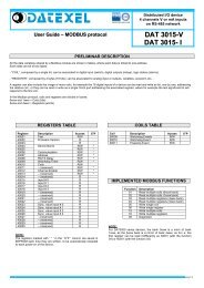
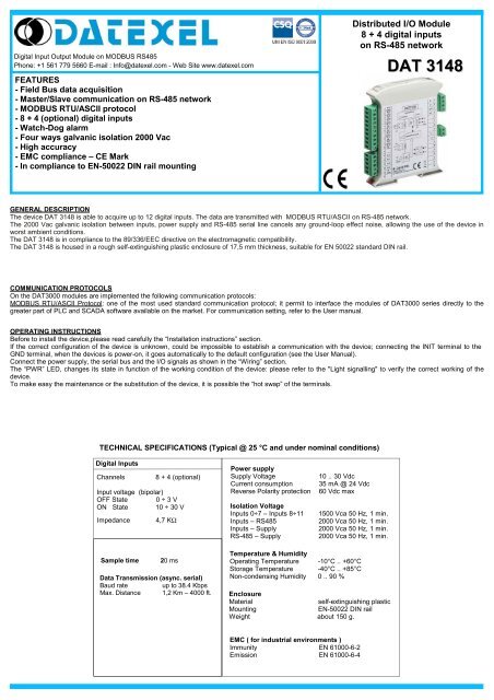
Distributed I/O <str<strong>on</strong>g>Module</str<strong>on</strong>g><br />
8 + 4 digital inputs<br />
<strong>on</strong> RS-485 network<br />
<str<strong>on</strong>g>Digital</str<strong>on</strong>g> <str<strong>on</strong>g>Input</str<strong>on</strong>g> Output <str<strong>on</strong>g>Module</str<strong>on</strong>g> <strong>on</strong> MODBUS <strong>RS485</strong><br />
Ph<strong>on</strong>e: +1 561 779 5660 E-mail : Info@datexel.com - Web Site www.datexel.com<br />
DAT 3148<br />
FEATURES<br />
- Field Bus data acquisiti<strong>on</strong><br />
- Master/Slave communicati<strong>on</strong> <strong>on</strong> RS-485 network<br />
- MODBUS RTU/ASCII protocol<br />
- 8 + 4 (opti<strong>on</strong>al) digital inputs<br />
- Watch-Dog alarm<br />
- Four ways galvanic isolati<strong>on</strong> 2000 Vac<br />
- High accuracy<br />
- EMC compliance – CE Mark<br />
- In compliance to EN-50022 DIN rail mounting<br />
GENERAL DESCRIPTION<br />
The device DAT 3148 is able to acquire up to 12 digital inputs. The data are transmitted with MODBUS RTU/ASCII <strong>on</strong> RS-485 network.<br />
The 2000 Vac galvanic isolati<strong>on</strong> between inputs, power supply and RS-485 serial line cancels any ground-loop effect noise, allowing the use of the device in<br />
worst ambient c<strong>on</strong>diti<strong>on</strong>s.<br />
The DAT 3148 is in compliance to the 89/336/EEC directive <strong>on</strong> the electromagnetic compatibility.<br />
The DAT 3148 is housed in a rough self-extinguishing plastic enclosure of 17,5 mm thickness, suitable for EN 50022 standard DIN rail.<br />
COMMUNICATION PROTOCOLS<br />
On the DAT3000 modules are implemented the following communicati<strong>on</strong> protocols:<br />
MODBUS RTU/ASCII Protocol: <strong>on</strong>e of the most used standard communicati<strong>on</strong> protocol; it permit to interface the modules of DAT3000 series directly to the<br />
greater part of PLC and SCADA software available <strong>on</strong> the market. For communicati<strong>on</strong> setting, refer to the User manual.<br />
OPERATING INSTRUCTIONS<br />
Before to install the device,please read carefully the “Installati<strong>on</strong> instructi<strong>on</strong>s” secti<strong>on</strong>.<br />
If the correct c<strong>on</strong>figurati<strong>on</strong> of the device is unknown, could be impossible to establish a communicati<strong>on</strong> with the device; c<strong>on</strong>necting the INIT terminal to the<br />
GND terminal, when the devices is power-<strong>on</strong>, it goes automatically to the default c<strong>on</strong>figurati<strong>on</strong> (see the User Manual).<br />
C<strong>on</strong>nect the power supply, the serial bus and the I/O signals as shown in the “Wiring” secti<strong>on</strong>.<br />
The “PWR” LED, changes its state in functi<strong>on</strong> of the working c<strong>on</strong>diti<strong>on</strong> of the device: please refer to the "Light signalling" to verify the correct working of the<br />
device.<br />
To make easy the maintenance or the substituti<strong>on</strong> of the device, it is possible the “hot swap” of the terminals.<br />
TECHNICAL SPECIFICATIONS (Typical @ 25 °C and under nominal c<strong>on</strong>diti<strong>on</strong>s)<br />
<str<strong>on</strong>g>Digital</str<strong>on</strong>g> <str<strong>on</strong>g>Input</str<strong>on</strong>g>s<br />
Channels 8 + 4 (opti<strong>on</strong>al)<br />
<str<strong>on</strong>g>Input</str<strong>on</strong>g> voltage (bipolar)<br />
OFF State 0 ÷ 3 V<br />
ON State 10 ÷ 30 V<br />
Impedance 4,7 KΩ<br />
Power supply<br />
Supply Voltage<br />
Current c<strong>on</strong>sumpti<strong>on</strong><br />
Reverse Polarity protecti<strong>on</strong><br />
Isolati<strong>on</strong> Voltage<br />
<str<strong>on</strong>g>Input</str<strong>on</strong>g>s 0÷7 – <str<strong>on</strong>g>Input</str<strong>on</strong>g>s 8÷11<br />
<str<strong>on</strong>g>Input</str<strong>on</strong>g>s – <strong>RS485</strong><br />
<str<strong>on</strong>g>Input</str<strong>on</strong>g>s – Supply<br />
RS-485 – Supply<br />
10 .. 30 Vdc<br />
35 mA @ 24 Vdc<br />
60 Vdc max<br />
1500 Vca 50 Hz, 1 min.<br />
2000 Vca 50 Hz, 1 min.<br />
2000 Vca 50 Hz, 1 min.<br />
2000 Vca 50 Hz, 1 min.<br />
Sample time<br />
20 ms<br />
Data Transmissi<strong>on</strong> (async. serial)<br />
Baud rate up to 38.4 Kbps<br />
Max. Distance 1,2 Km – 4000 ft.<br />
Temperature & Humidity<br />
Operating Temperature -10°C .. +60°C<br />
Storage Temperature -40°C .. +85°C<br />
N<strong>on</strong>-c<strong>on</strong>densing Humidity 0 .. 90 %<br />
Enclosure<br />
Material self-extinguishing plastic<br />
Mounting EN-50022 DIN rail<br />
Weight about 150 g.<br />
EMC ( for industrial envir<strong>on</strong>ments )<br />
Immunity EN 61000-6-2<br />
Emissi<strong>on</strong> EN 61000-6-4
I<br />
INSTALLATION INSTRUCTIONS<br />
WIRING<br />
The device DAT 3148 is suitable to be mounted <strong>on</strong> DIN rail, in vertical positi<strong>on</strong>.<br />
For a correct working and a l<strong>on</strong>g life of the device, read the following indicati<strong>on</strong>s.<br />
DIGITAL INPUT WIRING<br />
In case of the devices are mounted side by side, please leave about 5mm<br />
between in the following situati<strong>on</strong>s:<br />
- Temperature in the cabinet higher than 45 °C and high supply voltage<br />
( >27Vdc ).<br />
Avoid to place raceways or other objects which could obstruct the ventilati<strong>on</strong><br />
slits. It is suggested to avoid that devices are mounted above appliances<br />
generating heat; their ideal place should be in the lower part of the panel.<br />
Avoid to install the devices in a site where vibrati<strong>on</strong>s are present.<br />
It is recommended to use shielded cable for c<strong>on</strong>necting signals. The shield must<br />
be c<strong>on</strong>nected to an earth wire provided for this purpose. Moreover it is suggested<br />
to avoid routing c<strong>on</strong>ductors near power signal cables.<br />
9<br />
1<br />
2<br />
3<br />
DI0<br />
DI1<br />
DI2<br />
15<br />
11<br />
12<br />
13<br />
DI8<br />
DI9<br />
DI10<br />
4<br />
DI3<br />
14<br />
DI11<br />
CABLING<br />
5<br />
DI4<br />
DI5<br />
Only for DAT 3148/12<br />
SHIELD<br />
6<br />
RS-485<br />
D+<br />
D-<br />
V-<br />
V+<br />
7<br />
8<br />
DI6<br />
DI7<br />
INIT<br />
A<br />
B<br />
C<br />
D<br />
J<br />
NOTES: <str<strong>on</strong>g>Input</str<strong>on</strong>g> channels 0÷7 are insulated from input channels 8÷11<br />
RS-485 NETWORK WIRING<br />
INIT WIRING<br />
INPUTS 0÷7<br />
9<br />
10<br />
11<br />
12<br />
13<br />
14<br />
15<br />
1<br />
2<br />
3<br />
4<br />
5<br />
6<br />
7<br />
8<br />
A<br />
B<br />
C<br />
D -<br />
D +<br />
GND<br />
(-)<br />
(+)<br />
RS-485<br />
NETWORK<br />
D<br />
C<br />
INIT<br />
GND<br />
ON: short-circuit<br />
to GND<br />
INPUTS 8÷11<br />
POWER SUPPLY WIRING<br />
LIGHT SIGNALLING<br />
LED COLOUR STATE DESCRIPTION<br />
J<br />
I<br />
+V<br />
-V<br />
+<br />
10÷30 Vdc<br />
-<br />
PWR GREEN ON<br />
Device powered<br />
OFF<br />
RAPID BLINK<br />
SLOW BLINK<br />
Device not powered or wr<strong>on</strong>g RS-485 c<strong>on</strong>necti<strong>on</strong><br />
Communicati<strong>on</strong> in progress (the blink frequency<br />
depends to the Baud-rate)<br />
~1 sec. - Watch-Dog Alarm c<strong>on</strong>diti<strong>on</strong><br />
ISOLATION DIAGRAM<br />
INPUTS 0÷7<br />
<strong>RS485</strong><br />
MECHANICAL DIMENSIONS (mm)<br />
INPUTS 8÷11<br />
POWER SUPPLY<br />
100<br />
HOW TO ORDER<br />
In the order phase it is mandatory to specify the number of inputs (8 or 12)<br />
DAT 3148 / 8<br />
<str<strong>on</strong>g>Input</str<strong>on</strong>g> number:<br />
8: 8 inputs.<br />
12: 8+4 inputs.<br />
= Mandatory<br />
17,5<br />
120<br />
= Opti<strong>on</strong>al<br />
<strong>Datexel</strong> reserves its right to modify the characteristics of its products totally or in part without warning at any time.<br />
ED.10.06 REV.03