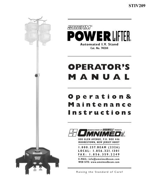
Operation& Maintenance Instructions OPERATOR'S MANUAL
Operation& Maintenance Instructions OPERATOR'S MANUAL
Operation& Maintenance Instructions OPERATOR'S MANUAL

You also want an ePaper? Increase the reach of your titles
YUMPU automatically turns print PDFs into web optimized ePapers that Google loves.
Automated I.V. Stand<br />
Cat. No. 741314<br />
OPERATOR’S<br />
<strong>MANUAL</strong><br />
Operation&<br />
<strong>Maintenance</strong><br />
<strong>Instructions</strong><br />
Raising the Standard of Care!<br />
STIV209<br />
®
Table of Contents<br />
Warranty . . . . . . . . . . . . . . . . . . . . . . . 2<br />
Hardware . . . . . . . . . . . . . . . . . . . . . . . 2<br />
Assembly <strong>Instructions</strong> . . . . . . . . . . . . 3, 4<br />
Operation . . . . . . . . . . . . . . . . . . . . . . . 5<br />
Charging . . . . . . . . . . . . . . . . . . . . . . . . 5<br />
Fuse Replacement . . . . . . . . . . . . . . . . . 5<br />
<strong>Maintenance</strong> . . . . . . . . . . . . . . . . . . . . . 6<br />
Trouble Shooting . . . . . . . . . . . . . . . . . . 6<br />
Parts List . . . . . . . . . . . . . . . . . . . . . . . 7<br />
Wiring Diagram . . . . . . . . . . . . . . . . . . . 8<br />
2<br />
Assembly Components<br />
Unpack the two cartons and check carefully to determine that all of the above parts have been supplied.<br />
Base and Cover Assembly<br />
Hardware Packet Including:<br />
Pole Locking Knob<br />
1 ⁄8" Hex Key<br />
Column Assembly<br />
Hanger Assembly<br />
STIV209<br />
Warranty<br />
Omnimed ® warrants the products described herein insofar as the same<br />
are of its own manufacture against defects in material and workmanship<br />
under normal use and service for a period of 6 months from date of<br />
purchase. Omnimed ® shall not be held responsible for any difficulty,<br />
damages, or warranty infringement which in the opinion of Omnimed ®<br />
have resulted from overloading, misuse, negligence, alteration, accident,<br />
or service that may arise from faulty installation. The obligation of<br />
Omnimed ® under this warranty is limited to furnishing, repairing, or<br />
replacing (FOB factory) any part of its own manufacture proven to have<br />
been defective at the time of shipment, provided the purchaser has<br />
given Omnimed ® immediate written notice upon discovery of the<br />
defect. Omnimed ® shall have the option of requiring inspection of<br />
defective material (transportation prepaid) to establish the claim.<br />
This warranty is the only warranty expressed or implied. Omnimed ®<br />
neither assumes nor authorizes any other person to assume for it any<br />
obligation or liability. Omnimed ® is not responsible nor liable for any<br />
consequential or contingent damages, and its liability is limited solely to<br />
the options hereinabove set forth.<br />
Any component parts not of Omnimed ® ’s own manufacture carry only<br />
the warranty extended to Omnimed ® by the respective suppliers or<br />
makers of such parts.<br />
All prior agreements, oral or written, referring to the Power Lifter ® are<br />
hereby canceled. The provisions in the specifications attached hereto<br />
are not intended as warranties.<br />
Battery Charger Assembly
Assembly <strong>Instructions</strong><br />
1) Use the 1 ⁄8 hex key<br />
to loosen the three<br />
set screws in the<br />
upper flanges of the<br />
base legs. Lift the<br />
cover from the Base<br />
and set it aside.<br />
2) Remove the nut and washers from the base of the column. Insert the column stud<br />
through the hole in the center of the base, taking care not to pinch any wires or hoses.<br />
Rotate the column so that the caution label on the locking collar at the top of the column<br />
faces forward. Use the nut and washers to tighten the column securely to the base.<br />
4) Slide the connector from the red wire onto the<br />
positive (+) battery terminal.<br />
3) Attach the air hose to the pressure release valve by<br />
pushing it firmly into the connector.<br />
STIV209<br />
3
4<br />
5) Loosen the setscrew in<br />
the rear of the locking collar.<br />
Remove the locking collar<br />
from the top of the column.<br />
Assembly <strong>Instructions</strong> (continued)<br />
7) Return the locking<br />
collar to the top of<br />
the column and tighten<br />
the serscrew, being<br />
careful to align it with<br />
the recess in the column.<br />
8) Thread the column<br />
locking knob into the<br />
front of the locking collar<br />
and tighten until snug.<br />
9) Insert the hanger assembly<br />
into the top of the pole with the<br />
setscrew in the hanger shaft<br />
aligned with the hole in the<br />
pole. Insert the hex key<br />
through the hole and tighten the<br />
setscrew snugly.<br />
6) Slide the<br />
Cover over the column<br />
onto its original<br />
position on the base<br />
and secure it with the<br />
3 setscrews.<br />
Your Power Lifter ® is now fully assembled. Be sure to fully charge the battery before beginning operation.<br />
STIV209
Charging<br />
1) A daily overnight routine should be established for charging your<br />
Power Lifter ® The charger is UL 2601-1 approved for Medical<br />
Devices. To charge the unit, plug the charging into a 120 Volt AC wall<br />
outlet. The green indicator LED should light.<br />
2) Locate the charging receptacle on the outside wall of the Power<br />
Lifter ® base and lift the protective cover.<br />
3) Align the flat surfaces on the plug and receptacle and insert the<br />
plug. Tighten the locking ring on the outside of the plug to ensure a<br />
good connection. When connected, the LED should turn amber.<br />
When the LED turns green the unit is fully charged.<br />
Operation<br />
1) Prior to operating the Power Lifter ® , be sure that the battery is<br />
fully charged. <strong>Instructions</strong> for recharging are listed above. Note<br />
that the unit will not operate when the battery charger is<br />
connected.<br />
2) In order to raise or lower a load, the Pole Locking Knob must<br />
be loosened. Tighten the knob to maintain position of the pole<br />
once solution bags have been loaded and raised.<br />
3) To raise a load, first make sure the locking knob has been<br />
loosened. Press the “UP” pedal until the load is at the proper<br />
level. After releasing the pedal, tighten the locking knob to lock<br />
the load in position.<br />
4) To lower a load, depress the “DOWN” pedal for several<br />
seconds to release any excessive cylinder pressure. Then, loosen<br />
the locking knob. If necessary, depress the pedal to further lower<br />
the load.<br />
Fuse Replacement<br />
1) If your Power Lifter ® fails to operate when charged, check the condition<br />
of the fuse. The fuse is located on the outside wall of the base.<br />
To remove the fuse, press in on the fuse holder knob and rotate it 1 ⁄4<br />
turn counter-clockwise. Pull the knob and fuse from the receptacle.<br />
2) If the fuse element is broken, remove the fuse from the knob and<br />
replace it with a 10 amp, 32 Volt, Slo-Blo fuse.<br />
3) Re-insert the fuse and knob into the receptacle, press inward, and<br />
rotate 1 ⁄4 turn clockwise.<br />
STIV209<br />
5
6<br />
<strong>Maintenance</strong><br />
The Power Lifter ® was designed to require only a minimal amount of periodic maintenance. The casters should be checked<br />
monthly to insure they rotate and pivot freely. Any defective caster should be replaced immediately. The Seal at the<br />
base of the pole should be cleaned and relubricated annually using Nevastane 5 or silicone spray following the instructions<br />
below:<br />
1) Before starting to disassemble the unit, exhaust any compressed air from the chambers by depressing the “DOWN”<br />
pedal.<br />
2) Remove the Hanger Assembly from the top of the pole. Insert a 1 ⁄8 hex key through the hole near the top of the pole<br />
and loosen the Hanger assembly setscrew. Pull the assembly upward and out of the pole.<br />
3) Remove the Locking Collar and Knob. First, loosen the setscrew on the rear of the collar and the knob on its front. Lift<br />
the assembly up and over the inner column.<br />
4) Pull the pole from the column with the “DOWN” pedal depressed. Note that the upper bushing will be pulled from<br />
the chamber with the pole assembly.<br />
5) Wipe clean and relubricate the seal.<br />
6) With the “DOWN” pedal depressed, reinsert the pole into the column, being careful not to damage the seal.<br />
7) Press the Upper Pole Bushing flange flush with the top surface of the column.<br />
8) Replace the Locking Collar and the Hanger Assemblies. Be careful to align the locking collar setscrew with the recess in<br />
the column.<br />
Trouble Shooting<br />
The Power Lifter ® was designed to provide years of trouble-free operation with minimal maintenance. Should you encounter<br />
any difficulties, consult the list below for possible solutions.<br />
Problem: Motor does not operate.<br />
1) Check the fuse and if blown, replace as detailed in the operation instructions.<br />
2) Check the battery voltage (12.2 Volts minimum) and recharge as detailed in the operating instructions.<br />
3) Check the pump relay on the circuit board. The relay should operate with an audible click when the "Up" pedal is<br />
depressed.<br />
4) Check that the safety interlock relay on the circuit board operates when the charger is plugged into the unit.<br />
Problem: Motor operates but Column does not raise.<br />
1) Check all hose connections for possible air leaks.<br />
Problem: Pole does not lower.<br />
1) Check hoses for any kinks.<br />
STIV209
1 741315-01 Base<br />
2 7499324 Cover<br />
3 741314-PU "Up" Pedal<br />
4 741314-PD "Down" Pedal<br />
5 741314-15 Caster (qty 6)<br />
6 741314-25 Battery<br />
7 741314-26 Pump/Motor Assy<br />
8 741314-35 Pressure Release Valve Assy<br />
9 741314-43 Fuse Holder<br />
10 741314-40 Fuse, 10 Amp, 32 Volt Slo-Blo<br />
11 741314-29 Charger Input Connector<br />
12 741314-36 Foot Switch<br />
13 741314-10 Circuit Board<br />
14 741314-12 Column<br />
15 741314-20 Locking Collar w/Bushing<br />
Power Lifter ® Parts<br />
ITEM PART NO. DESCRIPTION ITEM PART NO. DESCRIPTION<br />
16 0299193 Locking Knob<br />
17 741314-86 Outer Tube O-Ring<br />
18 741314-67 Outer Tube Plug Assy<br />
19 741314-13 Inner Pole<br />
20 741314-18 Hanger Assembly<br />
21 741314-95 Garolite Tube<br />
22 7499298 Pole Bottom Plug<br />
23 0299707 Cup Retainer Washer<br />
24 741314-57 Buna Cup Seal (pkg 5)<br />
25 0299709 Pole Height Sleeve<br />
26 741314-28 Charger/Cord Assy (North America)<br />
741314-28E Charger/Cord Assy (European)<br />
27 741314-14 Nevastane 5 Lubricant<br />
(Purchase Separately)<br />
28 741318 Battery Indicator Kit (optional)<br />
STIV209<br />
7
8<br />
STIV209