Fan Coil Units - Kamco
Fan Coil Units - Kamco
Fan Coil Units - Kamco

Create successful ePaper yourself
Turn your PDF publications into a flip-book with our unique Google optimized e-Paper software.
<strong>Kamco</strong> Limited<br />
Unit 9, Curo Park, Frogmore, St Albans. AL2 2DD. United Kingdom<br />
Tel: +44 (0)1727 875020 Fax: +44 (o)1727 875335<br />
E-mail: info@kamco.co.uk www.kamco.co.uk<br />
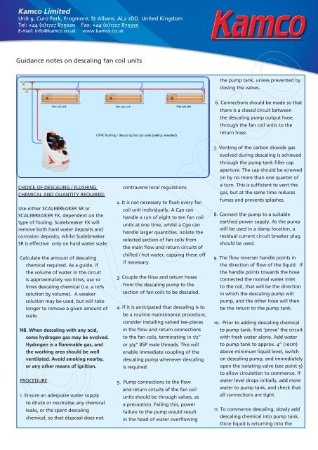
Guidance notes on descaling fan coil units<br />
CHOICE OF DESCALING / FLUSHING<br />
CHEMICAL AND QUANTITY REQUIRED:<br />
Use either SCALEBREAKER SR or<br />
SCALEBREAKER FX, dependent on the<br />
type of fouling. Scalebreaker FX will<br />
remove both hard water deposits and<br />
corrosion deposits, whilst Scalebreaker<br />
SR is effective only on hard water scale.<br />
Calculate the amount of descaling<br />
chemical required. As a guide, if<br />
the volume of water in the circuit<br />
is approximately 100 litres, use 10<br />
litres descaling chemical (i.e. a 10%<br />
solution by volume). A weaker<br />
solution may be used, but will take<br />
longer to remove a given amount of<br />
scale.<br />
NB. When descaling with any acid,<br />
some hydrogen gas may be evolved.<br />
Hydrogen is a flammable gas, and<br />
the working area should be well<br />
ventilated. Avoid smoking nearby,<br />
or any other means of ignition.<br />
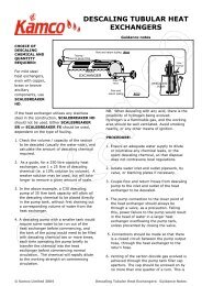
PROCEDURE<br />
1. Ensure an adequate water supply<br />
to dilute or neutralise any chemical<br />
leaks, or the spent descaling<br />
chemical, so that disposal does not<br />
contravene local regulations.<br />
2. It is not necessary to flush every fan<br />
coil unit individually. A C40 can<br />
handle a run of eight to ten fan coil<br />
units at one time, whilst a C90 can<br />
handle larger quantities. Isolate the<br />
selected section of fan coils from<br />
the main flow and return circuits of<br />
chilled / hot water, capping these off<br />
if necessary.<br />
3. Couple the flow and return hoses<br />
from the descaling pump to the<br />
section of fan coils to be descaled.<br />
4. If it is anticipated that descaling is to<br />
be a routine maintenance procedure,<br />
consider installing valved tee-pieces<br />
in the flow and return connections<br />
to the fan coils, terminating in 1/2”<br />
or 3/4” BSP male threads. This will<br />
enable immediate coupling of the<br />
descaling pump whenever descaling<br />
is required.<br />
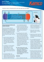
5. Pump connections to the flow<br />
and return circuits of the fan coil<br />
units should be through valves, as<br />
a precaution. Failing this, power<br />
failure to the pump would result<br />
in the head of water overflowing<br />
the pump tank, unless prevented by<br />
closing the valves.<br />
6. Connections should be made so that<br />
there is a closed circuit between<br />
the descaling pump output hose,<br />
through the fan coil units to the<br />
return hose.<br />
7. Venting of the carbon dioxide gas<br />
evolved during descaling is achieved<br />
through the pump tank filler cap<br />
aperture. The cap should be screwed<br />
on by no more than one quarter of<br />
a turn. This is sufficient to vent the<br />
gas, but at the same time reduces<br />
fumes and prevents splashes.<br />
8. Connect the pump to a suitable<br />
earthed power supply. As the pump<br />
will be used in a damp location, a<br />
residual current circuit breaker plug<br />
should be used.<br />
9. The flow reverser handle points in<br />
the direction of flow of the liquid. If<br />
the handle points towards the hose<br />
connected the normal water inlet<br />
to the coil, that will be the direction<br />
in which the descaling pump will<br />
pump, and the other hose will then<br />
be the return to the pump tank.<br />
10. Prior to adding descaling chemical<br />
to pump tank, first ‘prove’ the circuit<br />
with fresh water alone. Add water<br />
to pump tank to approx. 4” (10cm)<br />
above minimum liquid level, switch<br />
on descaling pump, and immediately<br />
open the isolating valve (see point 5)<br />
to allow circulation to commence. If<br />
© <strong>Kamco</strong><br />
water level drops initially, add more<br />
water to pump tank, and check that<br />
all connections are tight.<br />
11. To commence descaling, slowly add<br />
descaling chemical into pump tank.<br />
Once liquid is returning into the
tank from the circuit, check to see<br />
if there is a build up of foam on<br />
top of the liquid in the pump tank.<br />
This may happen when there is a<br />
large build up of reactive limescale<br />
in the coil. If this is excessive, add<br />
FOAMBREAKER carefully to the tank<br />
to reduce the foaming.<br />
12. As circulation commences, bubbles<br />
will be seen in the return hose to<br />
the pump, indicating that limescale<br />
is being dissolved.<br />
13. Continue circulation through the<br />
fan coils and descaling pump, briefly<br />
reversing the direction of flow<br />
periodically.<br />
14. Check all connections regularly for<br />
tightness and leaks, and if foaming<br />
is excessive, carefully remove<br />
descaling pump tank cap and<br />
add more FOAMBREAKER to the<br />
descaling pump tank.<br />
15. Scale removal can be considered<br />
complete when bubbles are no<br />
longer seen in the return pipe,<br />
and the descaling solution is still<br />
sufficiently strong to remove hard<br />
water deposits.<br />
16. SCALEBREAKER descaling chemicals<br />
contain a built-in colour change to<br />
monitor strength.<br />
A simple check may be made by<br />
dropping a sample of limescale into<br />
the solution, and observing if there<br />
is any effervescence.<br />
17. For more accuracy, a pH meter, or<br />
pH indicator paper, may be used<br />
to check the pH of the descaling<br />
solution. Once the pH has risen<br />
to 3.5 to 4, its ability to dissolve<br />
limescale is effectively spent, and<br />
more descaling chemical or a fresh<br />
solution will be required.<br />
18. If, after descaling has ceased, the<br />
pH of the descaling solution is<br />
still below 5, then the remaining<br />
solution must be neutralised to<br />
bring the pH level above 5, and<br />
as close to 7 as practicable. This<br />
may be done by slowly adding<br />
NEUTRALISING CRYSTALS or<br />
Neutralising Liquid to the tank of<br />
the descaling pump until there<br />
is no more effervescence as the<br />
crystals are added. When using<br />
Neutralising Crystals, if foaming is a<br />
problem during this operation, add<br />
FOAMBREAKER antifoam.<br />
19. After draining off the spent<br />
descaling chemical, flush the fan<br />
coil circuit with fresh water. Many<br />
natural waters are slightly alkaline,<br />
and water flushing may be all that<br />
is required. Alternatively, circulate<br />
a 1% solution of NEUTRALISING<br />
CRYSTALS through the coil for 15<br />
minutes, drain, and then flush with<br />
clean water once more.<br />
If you have a Scalebreaker C40 or C90<br />
descaling pump, this has an integral<br />
fresh water flushing facility:<br />
When descaling is complete, the spent<br />
descaling solution may be pumped to<br />
waste along the dump hose as follows:<br />
If the flow reverser lever is to the<br />
left, twist the right-hand dump valve<br />
through 180 o to show the word ‘dump’,<br />
ensuring that the left-hand valve<br />
remains in the ‘circulation’ position.<br />
(If the flow reverser lever is to the<br />
right, twist the left-hand dump valve<br />
through 180 o to show the word ‘dump’,<br />
ensuring that the right-hand valve<br />
remains in the ‘circulation’ position.)<br />
When ‘dumping’, the water level in the<br />
pump tank will fall by the same volume<br />
as is being dumped. Open the mains<br />
water supply valve and adjust to allow<br />
fresh water to enter the tank at the<br />
same rate as water is exiting the dump<br />
hose. Make sure that the tank water<br />
level remains at least 10 cm (4”) above<br />
the minimum mark.<br />
Continue dumping until fresh water is<br />
leaving the end of the dump hose.<br />
Turn the valve which is in ‘dump’ mode<br />
through 180 o to restore full circulation<br />
through the pump and the system.<br />
Close the water supply inlet valve once<br />
the level in the reservoir has stabilised<br />
between minimum and maximum<br />
markers.<br />
Allow fresh water to circulate through<br />
the descaled equipment for ten<br />
minutes.<br />
IMPORTANT: When working with<br />
acidic descaling chemicals, always<br />
wear suitable protective clothing and<br />
goggles. Refer to instructions on labels<br />
of descaling chemicals, and refer to<br />
Material Safety Data Sheets.<br />
Caps should be kept securely on all<br />
chemical containers whilst not in use.<br />
To avoid splashes, operators should not<br />
stand directly over the open neck of<br />
either chemical containers or the filling<br />
neck of the descaling pump whilst<br />
pouring or adding chemicals.<br />
Legal disclaimer: It is stressed that<br />
these are guidance notes only, and<br />
the above information is based on<br />
the present state of our knowledge<br />
of calorifiers in general. It is given<br />
in good faith, but due to the<br />
diverse and varied nature of such<br />
equipment, the user must satisfy<br />
himself that the above procedure is<br />
viable in the prevailing situation.<br />
© <strong>Kamco</strong>