farad hybrid capacitor - Audio Design GmbH
farad hybrid capacitor - Audio Design GmbH
farad hybrid capacitor - Audio Design GmbH

Create successful ePaper yourself
Turn your PDF publications into a flip-book with our unique Google optimized e-Paper software.
RFC10HB – 10 FARAD<br />
HYBRID CAPACITOR<br />
Installation &<br />
Operation<br />
Serial Number: Date of Purchase:
INTRODUCTION<br />
Thank you for purchasing the Rockford Fosgate Hybrid Capacitor.The Rockford Hybrid Capacitors, also known as<br />
Electric Double Layer Capacitors (EDLC) or Super Capacitors, are passive electrostatic energy storage devices.They<br />
are state of the art technology that allows you to put massive power storage in a very small space<br />
What are Rockford Hybrid Capacitors good for?<br />
Some of the most promising applications that have been found for Rockford Hybrid Capacitors are battery and<br />
large audio system performance enhancement. Even the very best batteries, that present day technology has to<br />
offer, have performance limitations determined by the laws of physics and chemistry that govern their operation.<br />
Rockford Hybrid Capacitors supply their energy much faster than a battery. A properly installed Rockford Hybrid<br />
Capacitor can deliver the instantaneous power (Amps) that are commonly demanded by today's large audio<br />
systems.<br />
How do Rockford Hybrid Capacitors compare with Batteries?<br />
Rockford Hybrid Capacitors have approximately 10 times the power density of a same sized battery and the<br />
capability of being charged and discharged over 100 times faster than a battery.This is why they make such great<br />
intermediate power sources. However, Rockford Hybrid Capacitors do not have the characteristic battery limitations<br />
of a short life span, cold intolerance, and critical charge and discharge rates.<br />
What makes Rockford Hybrid Capacitor Cells so special?<br />
The electrode forming process, which produces ultra-dense yet porous <strong>hybrid</strong> electrodes, and the continuous<br />
operating voltage of 2.7 volts (per cell) give the Rockford Hybrid Capacitor the highest energy storage capacity and<br />
power density of any other commercially available components of comparable size and weight.<br />
To add the finishing touch to your new system order your Rockford Fosgate apparel, which include everything from<br />
T-shirts and jackets to hats and sunglasses.<br />
To get a free brochure on Rockford Fosgate products and apparel,<br />
in the U.S. call 480-967-3565 or FAX 480-967-8132.<br />
For all other countries, call +001-480-967-3565 or FAX +001-480-967-8132.<br />
Or, visit our web site at www.rockfordfosgate.com<br />
If, after reading your manual, you still have questions regarding this product, we recommend<br />
that you see your Rockford Fosgate dealer. If you need further assistance, you can call us direct at<br />
1-800-669-9899. Be sure to have your model number and date of purchase available when you call.<br />
(Outside U.S. call 1-480-967-3565)<br />
TABLE OF CONTENTS<br />
Introduction. . . . . . . . . . . . . . . . . . . . . . . . . 2<br />
Safety Instructions . . . . . . . . . . . . . . . . . . . 3<br />
Contents of Carton. . . . . . . . . . . . . . . . . . . 3<br />
<strong>Design</strong> Features. . . . . . . . . . . . . . . . . . . . . . 4<br />
Safety Features. . . . . . . . . . . . . . . . . . . . . . . . 4<br />
NOTE: Review each section for more detailed information.<br />
2<br />
Installation . . . . . . . . . . . . . . . . . . . . . . . . 4-7<br />
Installation Considerations . . . . . . . . . . . . . . 4<br />
Mounting Locations. . . . . . . . . . . . . . . . . . . . 5<br />
Wiring the System. . . . . . . . . . . . . . . . . . . . . 5<br />
Specifications . . . . . . . . . . . . . . . . . . . . . . . . 8<br />
Limited Warranty Information . . . . . . . . . 9<br />
2006 Rockford Corporation.All rights reserved.<br />
Rockford Fosgate, the Rockford Fosgate logo, and the PUNCH logo are either<br />
registered trademarks or trademarks of Rockford Corporation.
Visit our web site for the latest information on all Rockford products.<br />
www.rockfordfosgate.com<br />
SAFETY INSTRUCTIONS<br />
This symbol with “WARNING” is intended to alert the user to the<br />
presence of important instructions. Failure to heed the instructions<br />
will result in severe injury or death.<br />
This symbol with “CAUTION” is intended to alert the user to the<br />
presence of important instructions. Failure to heed the instructions<br />
can result in injury or unit damage.<br />
CAUTION: To prevent injury and damage to the unit, please read and follow the<br />
instructions in this manual.We want you to have enjoyment from this<br />
system, not a headache.<br />
CAUTION: If you feel unsure about installing this system yourself, have it installed by a<br />
qualified Rockford Fosgate technician.<br />
CAUTION: Before installation, disconnect the battery negative (-) and positive (+)<br />
terminal to prevent damage to the unit, fire and/or possible injury.<br />
WARNING:To prevent serious personal injury, fire and/or damage, ensure the <strong>capacitor</strong><br />
has been properly discharged before servicing the vehicle and/or system<br />
components.<br />
CAUTION: Failure to observe the following safety precautions could result in damage<br />
to the <strong>capacitor</strong>, vehicle and/or personal injury.<br />
• DO NOT allow metal objects, such as screwdrivers or other tools, to touch both<br />
<strong>capacitor</strong> terminals at the same time.The result may cause arcing and<br />
possible fire.<br />
• DO NOT use <strong>capacitor</strong> cells that have signs of damage, including cracks, leaks, or<br />
swelling.<br />
• DO NOT expose <strong>capacitor</strong> cells to flames, sparks or heat at any time.<br />
• DO NOT immerse <strong>capacitor</strong> cells in water or allow water to come into contact with<br />
them at any time.<br />
• DO NOT remove the electrolyte filling bolt from the top of a <strong>capacitor</strong> cell at any<br />
time.<br />
• DO NOT connect the positive (+) wire from the battery to the negative (–) terminal<br />
of the <strong>capacitor</strong>.<br />
• DO NOT connect the negative (–) wire from the battery to the positive (+) terminal<br />
of the <strong>capacitor</strong>.<br />
• DO NOT make any connections to a <strong>capacitor</strong> if the connecting polarity cannot be<br />
properly identified.Applying reversed polarity will damage <strong>capacitor</strong> cells.<br />
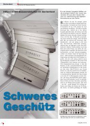
A model RFC10HB Hybrid Capacitor Module<br />
Installation & Operation Manual<br />
Charging Resistor<br />
Warning Label<br />
CONTENTS OF CARTON<br />
3
DESIGN FEATURES<br />
The following features are the results of the unique patented manufacturing process that enables the<br />
Rockford Hybrid Capacitor to deliver many charge and discharge cycles with greater energy and power<br />
per unit weight and volume.<br />
High Energy<br />
The amazingly high specific capacitance and lower weight of Rockford's Hybrid Capacitor yields an energy<br />
per kilogram figure that is twice that of any other commercially available Electric Double Layer Capacitor<br />
(EDLC).<br />
More Power<br />
Both the 'per weight' and 'per volume' power density of Rockford's Hybrid Capacitor exceeds that of<br />
other <strong>hybrid</strong> <strong>capacitor</strong>s in production today.The extremely low internal resistance (ESR) characteristic of<br />
Rockford's Hybrid Capacitor enables them to supply large amounts of instantaneous peak power, when<br />
demanded by the load.<br />
Long Life<br />
Rockford's Hybrid Capacitor has a very long life span as well.They have been subjected to more than<br />
500,000 charge and discharge cycles and only show a small typical loss of capacitance (less than 20%) and<br />
an even smaller than typical increase in ESR (less than 2X).The long life span of the Rockford's Hybrid<br />
Capacitor means that it may never need to be replaced.<br />
Excellent Low Temperature Performance<br />
Rockford's Hybrid Capacitors show very little loss of effective capacitance or ESR, even at temperatures as<br />
low as -°40F (-°40C).<br />
SAFETY FEATURES<br />
LED Display<br />
The display at the top of the Rockford Hybrid Capacitor will show the current voltage or the amperage<br />
current draw at the <strong>capacitor</strong>.<br />
Warning Buzzer<br />
The warning buzzer will sound if the Rockford Hybrid Capacitor has been wired to a reverse polarity.<br />
Safety Vent<br />
The safety vent ruptures when the internal pressure of <strong>capacitor</strong> cell has reached 5 ~ 10 kg/cm2.<br />
CAUTION: To prevent injury due to hazardous chemicals, do not touch the <strong>capacitor</strong><br />
if the safety vent has ruptured. Have the system looked at by a qualified<br />
technician for repair and/or disposal.<br />
ATTENTION: Safety vent ruptures caused by improper wiring is not covered under<br />
warranty.<br />
INSTALLATION<br />
INSTALLATION CONSIDERATIONS<br />
The following is a list of tools needed for installation:<br />
4<br />
Volt/Ohm Meter<br />
Wire strippers<br />
Wire crimpers<br />
Wire cutters<br />
Felt-tip pen or center punch<br />
#2 Phillips screwdriver<br />
3/16” Allen wrench<br />
5/32” Allen wrench<br />
Battery post wrench<br />
Hand held drill w/assorted bits<br />
Electrical tape<br />
Rubber or snap grommets<br />
Nylon tie straps<br />
Assorted connectors<br />
Adequate Length—Red Power Wire<br />
Adequate Length—Black Grounding Wire
INSTALLATION<br />
This section focuses on some of the vehicle considerations for installing your new Rockford Fosgate<br />
Hybrid Capacitor. Pre-planning your system layout and best wiring routes will save installation time.<br />
When deciding on the layout of your new system, be sure that each component will be easily accessible<br />
for making adjustments.<br />
CAUTION: If you feel unsure about installing this system yourself, have it installed by<br />
a qualified Rockford Fosgate technician.<br />
CAUTION: Before installation, disconnect the battery negative (-) and positive (+)<br />
terminals to prevent damage to the unit, fire and/or possible injury.<br />
Before beginning any installation, follow these simple rules:<br />
1. Be sure to carefully read and understand the instructions before attempting to install the unit.<br />
2. For safety, disconnect the negative lead from the battery prior to beginning the installation.<br />
3. For easier assembly, we suggest you run all wires prior to mounting your unit in place.<br />
4. Route all of the high current wires close together and away from any RCA cables.<br />
5. Use high quality connectors for a reliable installation and to minimize signal or power loss.<br />
6. Think before you drill! Be careful not to cut or drill into gas tanks, fuel lines, brake or hydraulic lines,<br />
vacuum lines or electrical wiring when working on any vehicle.<br />
7. Never run wires underneath the vehicle. Running the wires inside the vehicle provides the best<br />
protection.<br />
8. Avoid running wires over or through sharp edges. Use rubber or plastic grommets to protect any<br />
wires routed through metal, especially the firewall.<br />
9. ALWAYS protect the battery and electrical system from damage with proper fusing. Install the<br />
appropriate fuse holder and fuse on the +12V power wire within 18” (45.7 cm) of the battery<br />
terminal.<br />
10. When grounding to the chassis of the vehicle, scrape all paint from the metal to ensure a good, clean<br />
ground connection. Grounding connections should be as short as possible and always be connected to<br />
metal that is welded to the main body, or chassis, of the vehicle.<br />
MOUNTING LOCATIONS<br />
Select a dry location that will provide good ventilation around the Rockford Hybrid Capacitor.We<br />
recommend that you mount the <strong>capacitor</strong> on the floor of the trunk or in a location where<br />
it will be protected from water damage.<br />
• Mount in a location free from grease, water, flames, sparks or heat. Preferably in the trunk of the<br />
vehicle.<br />
• The <strong>capacitor</strong> should be mounted with the supplied screws as close to the amplifier as possible<br />
keeping the wire runs short. It is recommended that runs be kept less than 24 inches, as this will<br />
help to reduce voltage loss in the cables.<br />
• Mark the location where the <strong>capacitor</strong> is to be mounted.After wiring the system, mount the<br />
<strong>capacitor</strong> into place.<br />
WIRING THE SYSTEM<br />
CAUTION: If you do not feel comfortable with wiring your new unit, please see your<br />
local Authorized Rockford Fosgate Dealer for installation.<br />
CAUTION: Before installation, disconnect the battery negative (-) and positive (+)<br />
terminals to prevent damage to the unit, fire and/or possible injury.<br />
CAUTION: Avoid running power wires near the low level input cables, antenna, power<br />
leads, sensitive equipment or harnesses.The power wires carry substantial<br />
current and could induce noise into the audio system.<br />
CAUTION: Improper wiring connections can seriously damage the <strong>capacitor</strong> and/or<br />
your vehicle. Be sure to carefully follow the connection instructions in this<br />
manual. Improper wiring will void warranty.<br />
5
INSTALLATION<br />
ATTENTION: Make sure the battery and all other power sources are disconnected.<br />
ATTENTION: When installing high voltage audio equipment, such as <strong>capacitor</strong>s and<br />
amplifiers, we recommend using “full-spec” AWG (American Wire Gauge)<br />
type wire for your power and ground wires.<br />
CAUTION: Ensure correct polarity during the following connections. Failure to do<br />
so may cause damage to the unit when power is applied.<br />
NOTE:If a reverse polarity has been connected to the <strong>capacitor</strong>, a warning buzzer will sound when<br />
power is applied. Immediately disconnect the <strong>capacitor</strong> from power, ensure it has been<br />
discharged and reconnected to correct polarity.<br />
1. Attach the ground wire to the negative terminal block of the <strong>capacitor</strong>.The negative terminal is<br />
marked with a (–) Negative Connections.Attach the other end of the ground wire to the chassis<br />
of the car, ensure there is good metal to metal contact. Ensure that no stray wires are visible.<br />
Ensure all wires are secured. Loose connections will affect the performance of your <strong>capacitor</strong>,<br />
possibly leading to failure.<br />
2. Attach a fused Power wire to the positive terminal of the <strong>capacitor</strong>.The positive terminal is the<br />
platinum colored block marked with a (+) Positive Connections. Ensure that no stray wires are<br />
visible. Ensure all wires are secured. Loose connections will affect the performance of your <strong>capacitor</strong>,<br />
possibly leading to failure.<br />
3. To hook up your amplifier or distribution block, use the available 1/0 AWG and/or 4 AWG<br />
connections.<br />
4. Mount the unit securely in the location decided upon.<br />
Charging and connecting the Hybrid Capacitor to the battery<br />
ATTENTION: Charging your <strong>capacitor</strong> will ensure that the battery and <strong>capacitor</strong> voltage<br />
are equalized.This will help prevent arcing when the initial power connection<br />
to the <strong>capacitor</strong> is made.<br />
Overcharging cells will reduce their useful life span. HINT: Charging cells at an ambient temperature<br />
of less than +77°F (+25°C) will minimize the deterioration of their useful life span (keeping it near their<br />
500,000 cycle expectation).<br />
1. Make sure all power and ground connections are made at the <strong>capacitor</strong> module.<br />
6<br />
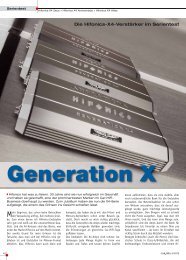
CHARGING CAPACITOR<br />
Connected to<br />
Can be used as<br />
Amplifier or System Ground<br />
Distribution Block Distribution Block<br />
Charging<br />
Resistor<br />
LEDs<br />
Green<br />
Red<br />
Connect to<br />
chassis ground<br />
of vehicle.<br />
Capacitor is charged<br />
when voltage is equal<br />
Keep Grounds<br />
as short as<br />
possible.<br />
Connected to<br />
Amplifier or System<br />
Distribution Block<br />
FINAL CONNECTION<br />
Can be used as<br />
Ground<br />
Distribution Block<br />
Connect to<br />
chassis ground<br />
of vehicle.<br />
Keep Grounds<br />
as short as<br />
possible.
INSTALLATION<br />
2. Reconnect the battery and any other power source that may have been disconnected.<br />
NOTE:If a reverse polarity has been connected to the <strong>capacitor</strong>, a warning buzzer will sound when<br />
power is applied. Immediately disconnect the <strong>capacitor</strong> from power, ensure it has been<br />
discharged and reconnected to correct polarity.<br />
3. Attach one end of the charging resistor to the power wire leading to the <strong>capacitor</strong> module. It is highly<br />
suggested that you place a fuse before the <strong>capacitor</strong>.This is to insure that if the <strong>capacitor</strong> were to be<br />
placed in reverse polarity it would blow the fuse first, not the cap.<br />
4. Attach the other end of the charging resistor to the positive battery post.<br />
5. The red LED will become dim and turn off after reaching battery voltage, usually 12.6 volts.This will<br />
take approximately 10 minutes.To achieve a more accurate reading, place the red lead of a voltmeter<br />
on the side of the charging resistor leading to the <strong>capacitor</strong> module (cap side of the fuse) and the<br />
black lead to chassis of the vehicle or to the negative battery clamp.<br />
6. Once a full charge has been reached and the <strong>capacitor</strong> module reads the same voltage as the battery,<br />
connect the power wire leading to the <strong>capacitor</strong> module to the positive battery post.Attention, small<br />
sparks may occur.<br />
7. At this point, it is very important to place the yellow warning label on the top of the battery or a<br />
highly visible location.This will let any persons know that an auxiliary form of power is hooked up. It<br />
is very very important that the <strong>capacitor</strong> module be discharged before performing any kind of service<br />
on the vehicle. It is important to remember that your Rockford Hybrid Capacitor could still be fully<br />
charged and could cause personal injury if not discharged.<br />
8. The Rockford Hybrid Capacitor is now ready for use.<br />
Discharging the Hybrid Capacitor<br />
WARNING:To prevent serious personal injury, fire and/or damage, ensure the <strong>capacitor</strong><br />
has been properly discharged before servicing the vehicle and/or system<br />
components.<br />
1. Disconnect the power wire going to the<br />
<strong>capacitor</strong> module from the battery.<br />
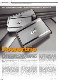
DISCHARGING CAPACITOR<br />
2. Attach one end of the charging resistor to the<br />
power wire leading to the <strong>capacitor</strong> module.<br />
3. Attach the other end of the charging resistor<br />
to the chassis of the vehicle or to the negative<br />
battery clamp.<br />
4. The green Led will become dim and turn off<br />
when discharging has been completed,<br />
approximately 10 minutes.Again to gain a<br />
more accurate reading, place the red lead of a<br />
voltmeter on the side of the charging resistor<br />
leading to the <strong>capacitor</strong> module (<strong>capacitor</strong><br />
side of the fuse) and the black lead to chassis<br />
of the vehicle or to the negative battery clamp.<br />
Charging<br />
Resistor<br />
LEDs<br />
Green<br />
Red<br />
Capacitor is discharged<br />
when voltage is Zero<br />
Connect to<br />
chassis ground<br />
of vehicle.<br />
Connect to<br />
chassis ground<br />
of vehicle.<br />
7
INSTALLATION<br />
DISPOSING OF HYBRID CAPACITOR CELLS<br />
A Rockford Hybrid Capacitor cell contains hazardous material, such as Acetonitrile (ACN).You must<br />
follow federal, state, and local laws when disposing of failed or aged cells. For more information, contact<br />
the Customer Support department of Rockford Corp. 1-800-669-9899. Capacitor modules that have<br />
reached their end-of-life can be recycled. Rockford Corp. will take back <strong>capacitor</strong> modules that need to<br />
be recycled. Rockford does not pay for shipping of returned <strong>capacitor</strong> modules that are to be recycled.<br />
CAUTION: To prevent injury due to hazardous chemicals, do not touch the <strong>capacitor</strong> if<br />
the safety vent has ruptured. Have the system looked at<br />
by a qualified technician for repair and/or disposal.<br />
SPECIFICATIONS<br />
MODEL- 10 Farad Hybrid Capacitor RFC10HB<br />
Rated Capacitance – 77°F (25°C) 10 Farad<br />
(Constant Current Discharge (5A) 15.0v–>3.0v)<br />
Capacitance Tolerance ±10%<br />
Rated Voltage,VR 16.0 Volts<br />
Surge Voltage 18.0 Volts<br />
Maximum Internal Resistance (ESR):
LIMITED WARRANTY INFORMATION<br />
Rockford Corporation offers a limited warranty on Rockford Fosgate products on the<br />
following terms:<br />
Length of Warranty<br />
One (1) Year (Proof of purchase required)<br />
If installed by an Authorized Rockford Fosgate Dealer, two (2) years<br />
(Proof of purchase required)<br />
What is Covered<br />
This warranty applies only to Rockford Fosgate products sold to consumers by Authorized<br />
Rockford Fosgate Dealers in the United States of America or its possessions. Product purchased<br />
by consumers from an Authorized Rockford Fosgate Dealer in another country are covered<br />
only by that country’s Distributor and not by Rockford Corporation.<br />
Who is Covered<br />
This warranty covers only the original purchaser of Rockford product purchased from an<br />
Authorized Rockford Fosgate Dealer in the United States. In order to receive service, the<br />
purchaser must provide Rockford with a copy of the receipt stating the customer name,<br />
dealer name, product purchased and date of purchase.<br />
Products found to be defective during the warranty period will be repaired or replaced<br />
(with a product deemed to be equivalent) at Rockford's discretion.<br />
What is Not Covered<br />
1. Damage caused by accident, abuse, improper operations, improper wiring, water, theft.<br />
2.Any cost or expense related to the removal or reinstallation of product.<br />
3. Service performed by anyone other than Rockford or an Authorized Rockford Fosgate<br />
Service Center.<br />
4.Any product which has had the serial number defaced, altered, or removed.<br />
5. Subsequent damage to other components.<br />
6.Any product purchased outside the U.S.<br />
7.Any product not purchased from an Authorized Rockford Fosgate Dealer.<br />
8. Broken or stripped screws.<br />
Limit on Implied Warranties<br />
Any implied warranties including warranties of fitness for use and merchantability are limited<br />
in duration to the period of the express warranty set forth above. Some states do not allow<br />
limitations on the length of an implied warranty, so this limitation may not apply. No person is<br />
authorized to assume for Rockford Fosgate any other liability in connection with the sale of<br />
the product.<br />
How to Obtain Service<br />
Please call 1-800-669-9899 for Rockford Customer Service.You must obtain an RA# (Return<br />
Authorization number) to return any product to Rockford Fosgate.You are responsible for<br />
shipment of product to Rockford.<br />
EU Warranty<br />
This product meets the current EU warranty requirements, see your Authorized dealer for<br />
details.<br />
9
NOTES<br />
10
NOTES<br />
11
Rockford Fosgate<br />
Rockford Corporation<br />
546 South Rockford Drive<br />
Tempe,Arizona 85281 U.S.A.<br />
In U.S.A., (480) 967-3565 - Customer Service 1-800-669-9899<br />
In Europe, Fax (49) 8503-934014<br />
In Japan, Fax (81) 559-79-1265<br />
www.rockfordfosgate.com<br />
12/06 B.M.<br />
1230-53683-01 Printed in China