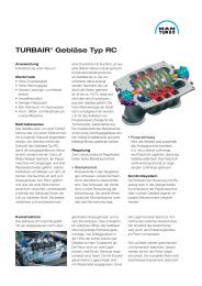
Download p367-0004.pdf (80kb) - MAN Diesel & Turbo
Download p367-0004.pdf (80kb) - MAN Diesel & Turbo
Download p367-0004.pdf (80kb) - MAN Diesel & Turbo

Create successful ePaper yourself
Turn your PDF publications into a flip-book with our unique Google optimized e-Paper software.
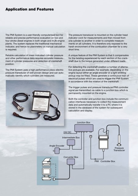
Application and Features<br />
The PMI System is a user-friendly computerised tool for<br />
reliable and precise performance evaluation on two and<br />
four stroke diesel engines in both single and multi-engine<br />
plants. The system replaces the traditional mechanical<br />
indicator, and hence no planimetery or manual calculation<br />
is required.<br />
Reliable calculation of mean indicated cylinder pressure<br />
and other performance data requires accurate measurement<br />
of cylinder pressures and detection of crankshaft<br />
position.<br />
The PMI System uses a high performance piezo-electric<br />
pressure transducer of well proven design and can automatically<br />
identify which cylinders are measured.<br />
The pressure transducer is mounted on the cylinder head<br />
indicator cock for measurements and then moved from<br />
one cylinder to another in order to complete measurements<br />
on all cylinders. It is therefore only exposed to the<br />
harsh environment of the combustion chamber for a very<br />
short time.<br />
A unique feature of the PMI System is that it compensates<br />
for the twisting experienced by each section of the crankshaft<br />
due to the torque generated under different loads.<br />
For detecting the crankshaft position a number of alternative<br />
pickups are available. For example, depending on the<br />
engine layout either an angle encoder or a light emitting<br />
pickup may be fitted. These generate a continuous train of<br />
electrical pulses which are used to trigger the PMI System<br />
in accordance with the rotation of the crankshaft.<br />
The trigger pulses and pressure transducer/PMI controller<br />
signal are transmitted via cable to a junction box which is<br />
permanently mounted on the engine.<br />
Both the controller and junction box include the communication<br />
interfaces necessary to collect the measurement<br />
data and automatically transfer it to a PC where it is<br />
stored in the database of the system for subsequent<br />
calculation and display.<br />
Junction Box<br />
24V DC<br />
Intermediate Box<br />
Angle Encoder<br />
Pressure<br />
Transducer<br />
Converter Box<br />
PMI Controller Box