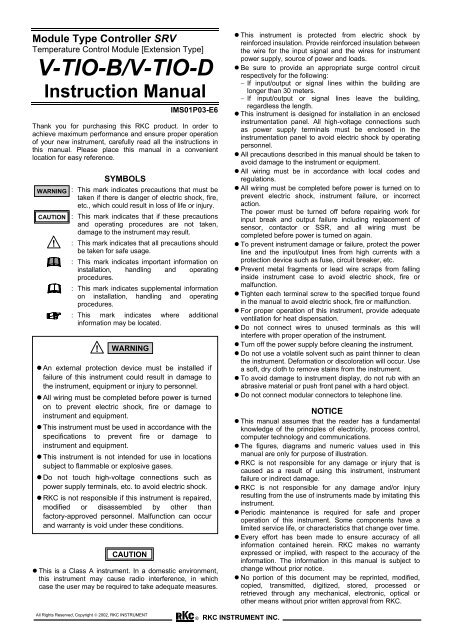
V-TIO-B/V-TIO-D - rkc instrument inc.
V-TIO-B/V-TIO-D - rkc instrument inc.
V-TIO-B/V-TIO-D - rkc instrument inc.

You also want an ePaper? Increase the reach of your titles
YUMPU automatically turns print PDFs into web optimized ePapers that Google loves.
Module Type Controller SRV<br />
Temperature Control Module [Extension Type]<br />
V-<strong>TIO</strong>-B/V-<strong>TIO</strong>-D<br />
Instruction Manual<br />
IMS01P03-E6<br />
Thank you for purchasing this RKC product. In order to<br />
achieve maximum performance and ensure proper operation<br />
of your new <strong>instrument</strong>, carefully read all the instructions in<br />
this manual. Please place this manual in a convenient<br />
location for easy reference.<br />
WARNING<br />
CAU<strong>TIO</strong>N<br />
!<br />
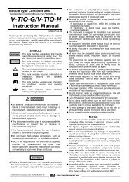
SYMBOLS<br />
: This mark indicates precautions that must be<br />
taken if there is danger of electric shock, fire,<br />
etc., which could result in loss of life or injury.<br />
: This mark indicates that if these precautions<br />
and operating procedures are not taken,<br />
damage to the <strong>instrument</strong> may result.<br />
: This mark indicates that all precautions should<br />
be taken for safe usage.<br />
: This mark indicates important information on<br />
installation, handling and operating<br />
procedures.<br />
: This mark indicates supplemental information<br />
on installation, handling and operating<br />
procedures.<br />
: This mark indicates where additional<br />
information may be located.<br />
! WARNING<br />
• An external protection device must be installed if<br />
failure of this <strong>instrument</strong> could result in damage to<br />
the <strong>instrument</strong>, equipment or injury to personnel.<br />
• All wiring must be completed before power is turned<br />
on to prevent electric shock, fire or damage to<br />
<strong>instrument</strong> and equipment.<br />
• This <strong>instrument</strong> must be used in accordance with the<br />
specifications to prevent fire or damage to<br />
<strong>instrument</strong> and equipment.<br />
• This <strong>instrument</strong> is not intended for use in locations<br />
subject to flammable or explosive gases.<br />
• Do not touch high-voltage connections such as<br />
power supply terminals, etc. to avoid electric shock.<br />
• RKC is not responsible if this <strong>instrument</strong> is repaired,<br />
modified or disassembled by other than<br />
factory-approved personnel. Malfunction can occur<br />
and warranty is void under these conditions.<br />
CAU<strong>TIO</strong>N<br />
• This is a Class A <strong>instrument</strong>. In a domestic environment,<br />
this <strong>instrument</strong> may cause radio interference, in which<br />
case the user may be required to take adequate measures.<br />
• This <strong>instrument</strong> is protected from electric shock by<br />
reinforced insulation. Provide reinforced insulation between<br />
the wire for the input signal and the wires for <strong>instrument</strong><br />
power supply, source of power and loads.<br />
• Be sure to provide an appropriate surge control circuit<br />
respectively for the following:<br />
− If input/output or signal lines within the building are<br />
longer than 30 meters.<br />
− If input/output or signal lines leave the building,<br />
regardless the length.<br />
• This <strong>instrument</strong> is designed for installation in an enclosed<br />
<strong>instrument</strong>ation panel. All high-voltage connections such<br />
as power supply terminals must be enclosed in the<br />
<strong>instrument</strong>ation panel to avoid electric shock by operating<br />
personnel.<br />
• All precautions described in this manual should be taken to<br />
avoid damage to the <strong>instrument</strong> or equipment.<br />
• All wiring must be in accordance with local codes and<br />
regulations.<br />
• All wiring must be completed before power is turned on to<br />
prevent electric shock, <strong>instrument</strong> failure, or <strong>inc</strong>orrect<br />
action.<br />
The power must be turned off before repairing work for<br />
input break and output failure <strong>inc</strong>luding replacement of<br />
sensor, contactor or SSR, and all wiring must be<br />
completed before power is turned on again.<br />
• To prevent <strong>instrument</strong> damage or failure, protect the power<br />
line and the input/output lines from high currents with a<br />
protection device such as fuse, circuit breaker, etc.<br />
• Prevent metal fragments or lead wire scraps from falling<br />
inside <strong>instrument</strong> case to avoid electric shock, fire or<br />
malfunction.<br />
• Tighten each terminal screw to the specified torque found<br />
in the manual to avoid electric shock, fire or malfunction.<br />
• For proper operation of this <strong>instrument</strong>, provide adequate<br />
ventilation for heat dispensation.<br />
• Do not connect wires to unused terminals as this will<br />
interfere with proper operation of the <strong>instrument</strong>.<br />
• Turn off the power supply before cleaning the <strong>instrument</strong>.<br />
• Do not use a volatile solvent such as paint thinner to clean<br />
the <strong>instrument</strong>. Deformation or discoloration will occur. Use<br />
a soft, dry cloth to remove stains from the <strong>instrument</strong>.<br />
• To avoid damage to <strong>instrument</strong> display, do not rub with an<br />
abrasive material or push front panel with a hard object.<br />
• Do not connect modular connectors to telephone line.<br />
NOTICE<br />
• This manual assumes that the reader has a fundamental<br />
knowledge of the pr<strong>inc</strong>iples of electricity, process control,<br />
computer technology and communications.<br />
• The figures, diagrams and numeric values used in this<br />
manual are only for purpose of illustration.<br />
• RKC is not responsible for any damage or injury that is<br />
caused as a result of using this <strong>instrument</strong>, <strong>instrument</strong><br />
failure or indirect damage.<br />
• RKC is not responsible for any damage and/or injury<br />
resulting from the use of <strong>instrument</strong>s made by imitating this<br />
<strong>instrument</strong>.<br />
• Periodic maintenance is required for safe and proper<br />
operation of this <strong>instrument</strong>. Some components have a<br />
limited service life, or characteristics that change over time.<br />
• Every effort has been made to ensure accuracy of all<br />
information contained herein. RKC makes no warranty<br />
expressed or implied, with respect to the accuracy of the<br />
information. The information in this manual is subject to<br />
change without prior notice.<br />
• No portion of this document may be reprinted, modified,<br />
copied, transmitted, digitized, stored, processed or<br />
retrieved through any mechanical, electronic, optical or<br />
other means without prior written approval from RKC.<br />
All Rights Reserved, Copyright © 2002, RKC INSTRUMENT<br />
® RKC INSTRUMENT INC.
1 2 3 4 50<br />
6 7 8 9<br />
0 1 2 3 49<br />
1. OUTLINE<br />
Two [basic types] of temperature control (<strong>TIO</strong>) modules are<br />
available: the V-<strong>TIO</strong>-B for heat control and the V-<strong>TIO</strong>-D for<br />
heat/cool control.<br />
As the temperature control (<strong>TIO</strong>) module [extension type] is not<br />
provide with power supply and host communication terminals,<br />
communication with the host computer is always made with this<br />
module connected to the temperature control (<strong>TIO</strong>) module<br />
[basic type]. In addition, one digital input (DI) point and two<br />
digital output (DO) points can be optionally added.<br />
All data are set by communication. For details, see the<br />
Module Type Controller SRV Communication Instruction<br />
Manual (IMS01P01-E).<br />
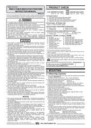
2. PRODUCT CHECK<br />
Before using this product, check each of the following:<br />
• Model code<br />
• Check that all of the accessories delivered are complete.<br />
• Check that there are no scratch or breakage in external<br />
appearance (case, front panel, or terminal, etc).<br />
*<br />
V–<strong>TIO</strong>– – – – – /Y<br />
(1) (2) (3) (4) (5) (6)(7)(8) (9)(10) (11) (12)<br />
(1) Type<br />
B: Extension type, heat control<br />
D: Extension type, heat/cool control<br />
(2) Control action<br />
[For heat control]<br />
F: PID action with autotuning (AT) (reverse action)<br />
D: PID action with autotuning (AT) (direct action)<br />
[For heat/cool control]<br />
B: Heat/cool PID action with autotuning (AT) (air cooling)<br />
W: Heat/cool PID action with autotuning (AT) (water cooling)<br />
(3) Input range (Each channel common code)<br />
[Thermocouple input]<br />
Type Code Range Code Range<br />
K K02 0 to 400 °C KB9 32 to 752 °F<br />
K04 0 to 800 °C KB8 32 to 1472 °F<br />
K16 −200 to +1372 °C KB7 −328 to +2501 °F<br />
K09 0.0 to 400.0 °C KC2 32.0 to 752.0 °F<br />
K35 −200.0 to +400.0 °C KC1 −328.0 to +752.0 °F<br />
J J02 0 to 400 °C JC2 32 to 752 °F<br />
J04 0 to 800 °C JC1 32 to 1472 °F<br />
J15 −200 to +1200 °C JB9 −328 to +2192 °F<br />
J09 0.0 to 400.0 °C JC4 32.0 to 752.0 °F<br />
J27 −200.0 to +400.0 °C JC3 −328.0 to +752.0 °F<br />
T T08 0 to 400 °C TB9 32 to 752 °F<br />
T09 0 to 200 °C TC1 32 to 392 °F<br />
T16 −200 to +400 °C TB8 −328 to +752 °F<br />
T06 0.0 to 400.0 °C TC3 32.0 to 752.0 °F<br />
T19 −200.0 to +400.0 °C TC2 −328.0 to +752.0 °F<br />
E E01 0 to 800 °C EA8 32 to 1472 °F<br />
E02 0 to 1000 °C EA7 32 to 1832 °F<br />
S S05 0 to 1768 °C SA6 32 to 3214 °F<br />
R R06 0 to 1768 °C RA6 32 to 3214 °F<br />
N N02 0 to 1300 °C NA6 32 to 2372 °F<br />
B B03 0 to 1800 °C BB1 32 to 3272 °F<br />
PLⅡ A02 0 to 1390 °C AA6 32 to 2534 °F<br />
W5Re/<br />
W26Re<br />
W03 0 to 2300 °C WA9 32 to 4172 °F<br />
[RTD input]<br />
Type Code Range Code Range<br />
Pt100 D17 0 to 400 °C DC5 32 to 752 °F<br />
D33 0 to 850 °C DC4 32 to 1562 °F<br />
D16 0.0 to 400.0 °C DC7 32.0 to 752.0 °F<br />
D28 −200.0 to +400.0 °C DC6 −328.0 to +752.0 °F<br />
JPt100 P17 0 to 400 °C PC5 32 to 752 °F<br />
P23 0 to 600 °C PC4 32 to 1112 °F<br />
P16 0.0 to 400.0 °C PC7 32.0 to 752.0 °F<br />
P28 −200.0 to +400.0 °C PC6 −328.0 to +752.0 °F<br />
[Voltage/current input]<br />
Code Type Code Type<br />
Voltage 201 0 to 100 mV DC 401 0 to 5 V DC<br />
501 0 to 10 V DC 601 1 to 5 V DC<br />
Current 701 0 to 20 mA DC 801 4 to 20 mA DC<br />
(4) Control output (CH1), (5) Control output (CH2)<br />
M: Relay contact output<br />
V: Voltage pulse output 0/12 V DC<br />
4: 0 to 5 V DC 5: 0 to 10 V DC 6: 1 to 5 V DC<br />
7: 0 to 20 mA DC 8: 4 to 20 mA DC<br />
(6) Event input (DI) [Optional]<br />
N: None<br />
1: Control RUN/STOP<br />
2: Event interlock release<br />
(7) (8) Event output 1 (DO1) [Optional]<br />
(9) (10) Event output 2 (DO2) [Optional]<br />
[(7), (9) code: Channel selection]<br />
N: None 1: Input channel 1 2: Input channel 2<br />
[(8), (10) code: Output type]<br />
N: None A: Deviation high B: Deviation low<br />
C: Deviation high/low D: Band<br />
E: Deviation high with hold action F: Deviation low with hold action<br />
G: Deviation high/low with hold action<br />
H: Process high J: Process low<br />
K: Process high with hold action L: Process low with hold action<br />
Q: Deviation high with re-hold action<br />
R: Deviation low with re-hold action<br />
T: Deviation high/low with re-hold action<br />
P: Heater break alarm 1: Control loop break alarm<br />
2: Burnout 3: Temperature rise completion<br />
(11) CT type (Each channel common code)<br />
P: CTL-6-P-N S: CTL-12-S56-10L-N<br />
(12) Communication function<br />
5: RKC communication (RS-485) 6: Modbus (RS-485)<br />
• For heat/cool PID control (V-<strong>TIO</strong>-D), input channel<br />
2 becomes unused.<br />
• For heat/cool PID control (V-<strong>TIO</strong>-D), Control output<br />
1 corresponds to the heating output and Control<br />
output 2 corresponds to the cooling output.<br />
• The heater break alarm function becomes invalid<br />
when the voltage/current output is selected as<br />
control output type.<br />
• Accessories<br />
Instruction Manual (IMS01P03-E6)............................1<br />
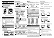
3. PARTS DESCRIP<strong>TIO</strong>N<br />
FAIL/RUN<br />
RX/TX<br />
EVENT1<br />
EVENT2<br />
EVENT3<br />
EVENT4<br />
7 8<br />
5 5 6<br />
Terminal<br />
cover<br />
Indication<br />
lamps<br />
Address<br />
setting<br />
switches<br />
Event<br />
input/<br />
output<br />
connector *<br />
Terminal<br />
cover<br />
FAIL/RUN<br />
When normally:<br />
A green lamp turns on (RUN)<br />
When abnormally:<br />
A red lamp turns on (FAIL)<br />
RX/TX<br />
During data send and receive:<br />
A green lamp turns on<br />
EVENT 1 to 4<br />
Display various states by setting.<br />
Display contents<br />
Event 1 state, Event 2 state,<br />
Comprehensive event state,<br />
Output state, Control state<br />
* Installed when provided with the event input/output (optional).<br />
2<br />
IMS01P03-E6
FAIL/RUN<br />
RX/TX<br />
EVENT1<br />
EVENT2<br />
EVENT3<br />
EVENT4<br />
0 1 2 3 49<br />
1 2 3 4 50<br />
1 2 3 4 50<br />
6<br />
5 6 7 8<br />
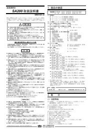
4. COMMUNICA<strong>TIO</strong>N SETTING<br />
Set communication setting before mounting and wiring of SRV.<br />
CAU<strong>TIO</strong>N<br />
Do not separate the module mainframe from the terminal<br />
base with the power turned on. If separated, adjusted data<br />
may be destroyed; control be stopped, and no return can be<br />
made.<br />
4.1 Module Address Setting<br />
Set an address of module. For this setting, use a small blade<br />
screwdriver.<br />
7 8 9<br />
5 5<br />
Address setting switch<br />
5 5 6<br />
9<br />
7 8<br />
6 7 8 9<br />
0<br />
1 2 3 4<br />
High-order digit setting<br />
(set value × 10)<br />
Low-order digit setting<br />
(set value × 1)<br />
Setting range: 0 to 99<br />
(Factory set value: 00)<br />
• For Modbus, the value obtained by adding “1” to the<br />
set address corresponds to the address used for the<br />
actual program.<br />
• To avoid problems or malfunction, do not duplicate<br />
an address on the same communication line.<br />
The above figure shows when provided with the event<br />
input/output connector, but the same also when not<br />
provided with the connector.<br />
4.2 Protocol Selections and<br />
Communication Speed Setting<br />
Use the DIP switch on the right side of module to select<br />
communication speed, data bit configuration and protocol. The<br />
data changes become valid when the power is turned on again<br />
or when changed to RUN/STOP.<br />
Terminal base<br />
Module mainframe<br />
Right side<br />
ON<br />
DIP switch<br />
1 2 3 4 5 6 7 8<br />
ON<br />
OFF<br />
• Switch No. 7 and 8 must be always OFF. Do not set to<br />
ON.<br />
• When two or more modules are connected on the<br />
same communication line, the DIP switch settings<br />
(switch 1 to 6) of all modules must be the same.<br />
• Be changed into communication time setting mode*<br />
by using switch No. 4, 5 and 6.<br />
For communication time setting mode, see the<br />
Module Type Controller SRV Communication<br />
Instruction Manual (IMS01P01-E).<br />
5. MOUNTING<br />
5.1 Mounting Cautions<br />
(1) This <strong>instrument</strong> is intended to be used under the following<br />
environmental conditions. (IEC61010-1)<br />
[OVERVOLTAGE CATEGORY II, POLLU<strong>TIO</strong>N DEGREE 2]<br />
(2) Use this <strong>instrument</strong> within the following environment conditions.<br />
• Allowable ambient temperature: −10 to +50 °C<br />
• Allowable ambient humidity: 5 to 95 % RH<br />
(Absolute humidity: MAX. W. C 29.3 g/m 3 dry air at 101.3 kPa)<br />
• Installation environment conditions: Indoor use<br />
Altitude up to 2000 m<br />
(3) Avoid the following when selecting the mounting location:<br />
• Rapid changes in ambient temperature, which may cause<br />
condensation.<br />
• Corrosive or inflammable gases.<br />
• Direct vibration or shock to the mainframe.<br />
• Water, oil, chemicals, vapor or steam splashes.<br />
• Excessive dust, salt or iron particles.<br />
• Excessive induction noise, static electricity, magnetic fields or<br />
noise.<br />
• Direct air flow from an air conditioner.<br />
• Exposure to direct sunlight.<br />
• Excessive heat accumulation.<br />
(4) Mounting consideration<br />
• Install the module 200 mm away from the main power line.<br />
• Ensure at least 50 mm space on top and bottom of the control<br />
unit for maintenance and environmental reasons.<br />
5.2 Dimensions<br />
! WARNING<br />
To prevent electric shock or <strong>instrument</strong> failure,<br />
always turn off the power before mounting or<br />
removing the <strong>instrument</strong>.<br />
(Unit: mm)<br />
110 6.8 30<br />
1 2 Communication speed<br />
OFF OFF 2400 bps<br />
ON OFF 9600 bps<br />
OFF ON 19200 bps<br />
ON ON 38400 bps<br />
Factory set value: RKC communication: 9600 bps<br />
Modbus:<br />
38400 bps<br />
3 4 5 Data bit configuration<br />
OFF OFF OFF Data 7-bit, without parity, Stop 1-bit *<br />
OFF OFF ON Data 7-bit, Even parity, Stop 1-bit *<br />
OFF ON ON Data 7-bit, Odd parity, Stop 1-bit *<br />
ON OFF OFF Data 8-bit, without parity, Stop 1-bit<br />
ON OFF ON Data 8-bit, Even parity, Stop 1-bit<br />
ON ON ON Data 8-bit, Odd parity, Stop 1-bit<br />
* When the Modbus communication protocol is selected,<br />
this setting becomes invalid.<br />
Factory set value: Data 8-bit, without parity, Stop 1-bit<br />
6 Protocol selection<br />
OFF<br />
RKC communication<br />
ON<br />
Modbus<br />
Factory set value: Specify when ordering<br />
IMS01P03-E6 3<br />
125<br />
5<br />
The above figure shows when provided with the event<br />
input/output connector, but the same also when not<br />
provided with the connector.<br />
78
• Depth in connector mounting<br />
Conduct installation in consideration of the sizes of the<br />
connector and cable when connector-connected.<br />
[Usage example of SRVP-01]<br />
110<br />
5.3 DIN rail Mounting<br />
• Mounting procedures<br />
Approx. 50<br />
(Unit: mm)<br />
Connector (plug):<br />
SRVP-01 (sold separately)<br />
1. Pull down the mounting bracket at the bottom of the module<br />
(A). Attach the hooks on the top of the module to the DIN rail<br />
and push the lower section into place on the DIN rail (B).<br />
(Fig. 1)<br />
2. Slide the mounting bracket up to secure the module to the<br />
DIN rail. (Fig. 2)<br />
5.4 Panel Mounting<br />
• Mounting procedures<br />
1. Pull down the mounting bracket (A) until locked and that a<br />
mounting hole appears.<br />
2. Prepare one mounting bracket per module (B) sold<br />
separately (KSRX-55) and then insert it in the rear of the<br />
terminal board at top of the module until locked but a<br />
mounting hole does not disappear.<br />
3. Mount each module directly on the panel with screws which<br />
are inserted in the mounting holes of the top and bottom<br />
mounting brackets.<br />
Recommended tightening torque: 0.3 N⋅m (3 kgf⋅cm)<br />
The customer needs to provide the M3 size screws.<br />
Select the screw length that matches the mounting<br />
panel.<br />
(B) Insert<br />
Mounting bracket<br />
(Sold separately)<br />
[KSRX-55]<br />
Mounting<br />
holes<br />
(A) Pull down<br />
DIN rail<br />
Mounting<br />
bracket<br />
(A) Pull down<br />
(B) Push<br />
Locked<br />
Fig. 1 Fig. 2<br />
• End Plate mounting<br />
Hold tight both ends of the modules jointed together with the end<br />
plates attached to the temperature control module [basic type]<br />
and then fix the end plates with screws.<br />
End Plate<br />
Temperature control module [basic type]<br />
Joint connector cover *<br />
End Plate<br />
* For the conservation of the contact of connector, install a joint<br />
connector cover (be attached to the <strong>TIO</strong> module [basic type]) in<br />
module of both ends.<br />
Mounting<br />
dimensions<br />
35.25 ± 0.2<br />
M3<br />
30 ± 0.2<br />
130.5 ± 0.2<br />
Module of 40.5 mm wide Module of 30 mm wide<br />
5.5 Jointing Each Module<br />
(Unit: mm)<br />
Up to 31 SRVs consisting of the each modules can be jointed<br />
together. Joint these modules according to the following<br />
procedure.<br />
• Jointing procedures<br />
1. Mount the modules on the DIN rail and then joint these<br />
modules together with the joint connector while sliding the<br />
relevant module.<br />
2. Lift each of the joint tabs located at the top and bottom of the<br />
module and then insert it in the slot of the adjacent module to<br />
fix these two modules.<br />
For panel mounting, first joint each module and then<br />
mount it on the panel.<br />
• Removing procedures<br />
Pull down a mounting bracket with a blade screwdriver (A). Lift<br />
the module from bottom, and take it off (B).<br />
Joint connector<br />
When viewed<br />
from top<br />
(A) Pull down<br />
(B) Lift and take off<br />
Joint tab<br />
There is one joint tab at each<br />
of the top and bottom of on<br />
module. Therefore, fix two<br />
adjacent modules with these<br />
two joint tabs.<br />
Joint tab<br />
insertion slot<br />
4<br />
IMS01P03-E6
6. WIRING<br />
6.3 Pin Layout of Connector<br />
• When there is the event input/output<br />
6.1 Wiring Cautions<br />
! WARNING<br />
To prevent electric shock or <strong>instrument</strong> failure, do<br />
not turn on the power until all the wiring is<br />
completed.<br />
• For thermocouple input, use the appropriate compensation<br />
wire.<br />
• For RTD input, use low resistance lead wire with no<br />
difference in resistance between the three lead wires.<br />
• To avoid noise induction, keep input signal wire away from<br />
<strong>instrument</strong> power line, load lines and power lines of other<br />
electric equipment.<br />
6.2 Terminal Configuration<br />
Event input/output<br />
connector (socket)<br />
• Circuit configuration<br />
1<br />
6<br />
Pin<br />
No.<br />
24 V DC<br />
Description<br />
1 Digital input (DI) (−)<br />
2 Digital input (DI) (+)<br />
3<br />
4<br />
5<br />
6<br />
Digital output (DO) 1<br />
(Relay contact output)<br />
Digital output (DO) 2<br />
(Relay contact output)<br />
7<br />
CT input Control output 1 Control output 2<br />
CT1<br />
3<br />
CT2<br />
6<br />
Voltage pulse/<br />
Current/<br />
Voltage<br />
OUT1<br />
+ −<br />
2<br />
5<br />
Relay contact<br />
2<br />
OUT1<br />
NO<br />
5<br />
Voltage pulse/<br />
Current/<br />
Voltage<br />
OUT2<br />
+ −<br />
1<br />
4<br />
Relay contact<br />
1<br />
OUT2<br />
NO<br />
4<br />
Load<br />
1<br />
DI<br />
2<br />
3<br />
DO1<br />
4<br />
3 2 1<br />
7 6 5 4<br />
Upper-side terminal<br />
Load<br />
5<br />
DO2<br />
6<br />
RTD1<br />
RTD<br />
Input channel 1<br />
10 10<br />
14 B 13 13<br />
A<br />
B<br />
IN1<br />
+ −<br />
Voltage/<br />
current<br />
11 10 9 8<br />
10<br />
14 13 12<br />
13<br />
TC1<br />
+ −<br />
Thermocouple<br />
9<br />
12<br />
IN2<br />
+ −<br />
Voltage/<br />
current<br />
Lower-side terminal<br />
Input channel 2<br />
9<br />
12<br />
TC2 + −<br />
Thermocouple<br />
9<br />
B<br />
12<br />
B<br />
RTD2<br />
RTD<br />
• For heat/cool PID control (V-<strong>TIO</strong>-D), Input channel<br />
2 becomes unused.<br />
• For heat/cool PID control (V-<strong>TIO</strong>-D), Control output<br />
1 corresponds to the heating output and Control<br />
output 2 corresponds to the cooling output.<br />
• Terminal No. 11 is not used.<br />
• Use the solderless terminal appropriate to the screw<br />
size (M3).<br />
8<br />
A<br />
6.4 Attention in Connector (plug) Wiring<br />
• Use the following connector (plug) as that connected to the<br />
event input/output connector.<br />
Connector (plug) is sold separately.<br />
SRVP-01 (Front-screw type)<br />
SRVP-02 (Side-screw type)<br />
• The lead wires use the stranded wire.<br />
• Use the stranded wire from size 0.2 to 2.5 mm 2 (AWG 24-12).<br />
• Stripping length is as follows.<br />
SRVP-01: 10 mm<br />
SRVP-02: 7 mm<br />
• Recommended tightening torque of the lead wire in the<br />
connector (plug): 0.5 to 0.6 N⋅m (5 to 6 kgf⋅cm)<br />
Screw size: SRVP-01: M2.5<br />
SRVP-01: M3<br />
5.9 mm or less<br />
3.2 mm or more<br />
Recommended tightening<br />
torque: 0.4 N⋅m (4 kgf⋅cm)<br />
IMS01P03-E6 5
[SRVP-01] Front-screw type<br />
[SRVP-02] Side-screw type<br />
• Events<br />
Number of events:<br />
Event type:<br />
2 points/channel<br />
Temperature event:<br />
Deviation high, Deviation low,<br />
Deviation high/low, Band,<br />
Process high, Process low<br />
Heater break alarm,<br />
Control loop break alarm,<br />
Burnout, Temperature rise completion<br />
Stripping length<br />
10 mm<br />
Stranded wire size:<br />
0.2 to 2.5 mm 2<br />
(AWG 24-12)<br />
Recommended tightening<br />
torque: 0.5 to 0.6 N⋅m<br />
(5 to 6 kgf⋅cm)<br />
7. SPECIFICA<strong>TIO</strong>NS<br />
• Inputs<br />
Number of inputs:<br />
Input type:<br />
• Thermocouple<br />
• RTD<br />
• Voltage (low)<br />
• Voltage (high)<br />
• Current<br />
Sampling cycle:<br />
PV bias:<br />
CT input:<br />
• Outputs<br />
Number of outputs:<br />
Output type:<br />
•Relay contact:<br />
•Voltage pulse:<br />
•Current:<br />
•Voltage:<br />
Stripping length<br />
7 mm<br />
Stranded wire size:<br />
0.2 to 2.5 mm 2<br />
(AWG 24-12)<br />
Recommended tightening<br />
torque: 0.5 to 0.6 N⋅m<br />
(5 to 6 kgf⋅cm)<br />
2 points<br />
Isolated between each channel:<br />
Thermocouple input, Voltage (low) input<br />
Not isolated between each channel:<br />
RTD input, Voltage (high) input,<br />
Current input<br />
K, J, T, S, R, E, B, N (JIS-C1602-1995)<br />
PLII (NBS)<br />
W5Re/W26Re (ASTM-E988-96)<br />
Pt100, JPt100<br />
0 to 100 mV<br />
0 to 5 V, 0 to 10 V, 1 to 5 V<br />
0 to 20 mA, 4 to 20 mA<br />
500 ms<br />
−Input span to +Input span<br />
2 points<br />
0.0 to 30.0 A (CTL-6P-N) or<br />
0.0 to 100.0 A (CTL-12-S56-10L-N)<br />
2 points<br />
(Isolated between input and output, and<br />
between output and power supply)<br />
250 V AC, 3 A (Resistive load)<br />
1a contact<br />
Electrical life 300,000 times or more<br />
(Rated load)<br />
0/12 V DC<br />
(Load resistance 600 Ω or more)<br />
0 to 20 mA DC, 4 to 20 mA DC<br />
(Load resistance 600 Ω or less)<br />
0 to 5 V DC, 0 to 10 V DC, 1 to 5 V DC<br />
(Load resistance 1 kΩ or more)<br />
• Option<br />
• Event input<br />
Number of inputs:<br />
Input type:<br />
Input voltage:<br />
Input current:<br />
Input details:<br />
• Event output<br />
Number of outputs:<br />
Output type:<br />
Output details:<br />
1 point<br />
Dry contact input<br />
24 V DC (Rated)<br />
Approx. 6 mA<br />
Control RUN/STOP,<br />
Event interlock release<br />
(Specify when ordering)<br />
2 points<br />
Relay contact output<br />
250 V AC, 1 A (Resistive load)<br />
1a contact<br />
Electrical life 300,000 times or more<br />
(Rated load)<br />
Temperature event, Heater break alarm,<br />
Control loop break alarm, Burnout,<br />
Temperature rise completion<br />
(Specify when ordering)<br />
• Communications<br />
Communication interface: Based on RS-485, EIA standard<br />
Communication protocol: RKC communication<br />
(ANSI X3.28 subcategory 2.5, A4)<br />
or Modbus<br />
Connection:<br />
Internal bus<br />
• Others<br />
Power supply voltage:<br />
24 V DC<br />
(The power is supplied from temperature<br />
control module [basic type].)<br />
Power supply voltage range:<br />
21.6 V DC to 26.4 V DC<br />
Current consumption:<br />
With event input/output (option):<br />
120 mA max./module<br />
Without event input/output (option):<br />
90 mA max./module<br />
Allowable ambient temperature range:<br />
−10 to +50 °C<br />
Allowable ambient humidity range:<br />
5 to 95 %RH (Non condensing)<br />
Absolute humidity:<br />
MAX.W.C 29.3 g/m 3 dry air at 101.3 kPa<br />
Installation environment conditions:<br />
Indoor use<br />
Altitude up to 2000 m<br />
Weight:<br />
With event input/output (option):<br />
Approx. 180 g<br />
Without event input/output (option):<br />
Approx. 170 g<br />
• Modbus is a registered trademark of Schneider Electric.<br />
• Company names and product names used in this manual are the<br />
trademarks or registered trademarks of the respective companies.<br />
• Control action<br />
Number of controls:<br />
Control method:<br />
Additional function:<br />
OCT. 2006<br />
2 points<br />
Brilliant PID control<br />
Reverse action or direct action is<br />
selectable (Specify when ordering)<br />
Heat/cool control is selectable<br />
(Specify when ordering)<br />
Autotuning function<br />
The first edition:<br />
The sixth edition:<br />
SEP. 2002 [IMQ00]<br />
OCT. 2006 [IMQ00]<br />
® RKC INSTRUMENT INC.<br />
HEADQUARTERS:16-6, KUGAHARA 5-CHOME, OHTA-KU<br />
TOKYO 146-8515 JAPAN<br />
PHONE: 03-3751-9799 (+81 3 3751 9799)<br />
E-mail: info@<strong>rkc</strong>inst.co.jp<br />
FAX: 03-3751-8585 (+81 3 3751 8585)<br />
IMS01P03-E6