Preparation of Titania Foams
Preparation of Titania Foams
Preparation of Titania Foams

You also want an ePaper? Increase the reach of your titles
YUMPU automatically turns print PDFs into web optimized ePapers that Google loves.
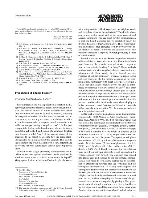
Communications<br />
Around 200 mg <strong>of</strong> sample was dissolved in 2 mL <strong>of</strong> 40 % aqueous HF solution<br />
for the sodium chemical analysis by atomic absorption using the standard<br />
addition method.<br />
Received: April 22, 1998<br />
Final version: July 8, 1998<br />
±<br />
[1] C. T. Kresge, M. E. Leonowickz, W. J. Roth, J. S. Beck, Nature 1992,<br />
359, 710.<br />
[2] J. S. Beck, J. C. Vartuli, W. J. Roth, M. E. Leonowicz, C. T. Kresge<br />
K. D. Schmitt, C. T.-W. Chu, D. H. Olson, E. W. Sheppard, S. B.<br />
McCullen, J. B. Higgins, J. L. Shlenker, J. Am. Chem. Soc. 1992, 114,<br />
10 834.<br />
[3] Q. Huo, D. Margolese, U. Ciesla, D. G. Demuth, P. Fenf, T. E. Gier, P.<br />
Gier, A. Firousi, B. F. Chmelka, F. Schüth, G. D. Stucky, Chem. Mater.<br />
1994, 6, 1176.<br />
[4] P. T. Tanev, T. J. Pinnavaia, Science 1995, 267, 885.<br />
[5] S. A. Bagshaw, E. Prouzet, T. J. Pinnavaia, Science 1995, 269, 1242.<br />
[6] P. Prouzet, J. Pinnavaia, Angew. Chem. Int. Ed. Engl. 1997, 36, 516.<br />
[7] R. Iler, The Chemistry <strong>of</strong> Silica, Wiley, New York 1979.<br />
[8] M. J. Schick, F. M. Fowkes, in Alkylene Oxides and their Polymers<br />
(Eds: F. E. Bailey, Jr., J. V. Koleske), Surfactant Science Series, Vol. 35,<br />
Marcel Dekker, New York 1991.<br />
[9] J. Rubio, J. A. Kitchner, J. Colloid Interface Sci. 1976, 57, 132.<br />
[10] K. Weckström, Chem. Phys. Lett. 1985, 119, 503.<br />
[11] A. Gellan, C. H. Rochester, J. Chem. Soc. Faraday Trans. 1 1985, 81,<br />
2235.<br />
<strong>Preparation</strong> <strong>of</strong> <strong>Titania</strong> <strong>Foams</strong>**<br />
By Arnout Imh<strong>of</strong> and David J. Pine*<br />
±<br />
[*] Pr<strong>of</strong>. D. J. Pine<br />
Department <strong>of</strong> Chemical Engineering<br />
University <strong>of</strong> California<br />
Santa Barbara, CA 93106 (USA)<br />
Dr. A. Imh<strong>of</strong><br />
Department <strong>of</strong> Materials<br />
University <strong>of</strong> California<br />
Santa Barbara, CA 93106 (USA)<br />
[**] This material is based on work supported by the US Army Research<br />
Office under grant number DAAG55-97-1-0372.<br />
Porous materials find wide application as sorption media,<br />
lightweight structural materials, filters, insulators, and catalysts.<br />
The microstructure <strong>of</strong> porous materials determines<br />
their usefulness but can be difficult to control, especially<br />
for inorganic materials. In order better to control the microstructure,<br />
we recently developed a technique in which<br />
an emulsion was used as a template to make materials with<br />
uniform macropores using a sol-gel process. [1,2] In that process<br />
partially hydrolyzed alkoxides were allowed to form a<br />
monolithic gel in the liquid outside the emulsion droplets,<br />
thus forming a solid ªcastº <strong>of</strong> the droplet phase <strong>of</strong> the<br />
emulsion. In this report we describe how the liquid alkoxides<br />
can also be emulsified inside the droplets. This leads to<br />
the formation <strong>of</strong> porous materials with a very different and<br />
interesting structure consisting <strong>of</strong> densely packed spherical<br />
shells.<br />
To facilitate the sol-gel processing <strong>of</strong> water-sensitive alkoxides<br />
we use non-aqueous emulsions, that is, emulsions in<br />
which the water phase is replaced by another polar liquid. [3]<br />
Many apolar liquids can be emulsified as droplets in formamide<br />
using certain triblock copolymers <strong>of</strong> ethylene oxide<br />
and propylene oxide as the surfactant. [3] The droplet phase<br />
can be any apolar liquid used in the more conventional<br />
aqueous emulsions. The key point for this communication<br />
is that the liquid alkoxides can be emulsified inside the<br />
droplets because <strong>of</strong> their apolar nature. These water-sensitive<br />
alkoxides are then protected from hydrolysis by the total<br />
absence <strong>of</strong> water. Hydrolysis and gelation occur only<br />
when the emulsion is exposed to water, producing a foam<br />
<strong>of</strong> spherical shells.<br />
Several other methods are known to produce ceramics<br />
with a cellular or foam microstructure. Examples <strong>of</strong> such<br />
procedures are the selective removal <strong>of</strong> one component<br />
from a composite by leaching [4] or firing. [5] These methods<br />
produce materials with irregularly shaped pores, which are<br />
interconnected. They usually have a limited porosity.<br />
Foaming <strong>of</strong> sol-gel solutions [6] produces spherical pores<br />
and high porosities like the method described in this communication,<br />
but typically with much larger pores (>10 mm).<br />
Small (but also large) spherical pores can also be introduced<br />
by sintering <strong>of</strong> hollow ceramic beads. [7,8] The latter<br />
technique has the added advantage that the pore size distribution<br />
can <strong>of</strong>ten be kept narrow, whereas our method in its<br />
present form yields a broad distribution. Advantages <strong>of</strong> our<br />
technique are that the ceramic precursor solution is easily<br />
prepared and is stable indefinitely, even when a highly reactive<br />
precursor is used. Furthermore, it leads to materials<br />
with extremely high porosities. Yet, the macropores do not<br />
seem to be interconnected.<br />
In this work we make titania foams using titanium tetraisopropoxide<br />
(TTIP, Aldrich, 97 %) as the alkoxide. Formamide<br />
(FA, Aldrich, >99 %, dried on molecular sieves 3A)<br />
was used as the polar liquid. The surfactant was the triblock<br />
copolymer (ethylene glycol) 20 ±(propylene glycol) 70 ±(ethylene<br />
glycol) 20 , obtained from Aldrich. Its molecular weight<br />
is 5800 and it contains 30 % by weight <strong>of</strong> ethylene glycol<br />
monomer. A solution <strong>of</strong> 1.75 % by weight <strong>of</strong> the surfactant<br />
in FA served as the polar phase. The apolar, or oil, phase<br />
was a mixture <strong>of</strong> 25 % by volume <strong>of</strong> titanium tetraisopropoxide,<br />
74 % isooctane (2,2,4-trimethylpentane, Aldrich,<br />
99 %), and 1 % silicon oil (Fisher, boiling point >200 C,<br />
density = 0.959 g/mL). Equal volumes <strong>of</strong> the two solutions<br />
were mixed in a nitrogen atmosphere and agitated until a<br />
viscous emulsion was formed. The emulsion was poured<br />
into plastic cups and exposed to the atmosphere. Immediately,<br />
a skin began to form on the surface due to the diffusion<br />
<strong>of</strong> atmospheric moisture into the formamide and the<br />
subsequent hydrolysis <strong>of</strong> TTIP residing in the droplets. The<br />
atmospheric moisture was not controlled or measured. As<br />
the skin grew thicker the reaction slowed down. Water has<br />
a higher density than the emulsion so it could not be added<br />
from the top without disrupting the formation <strong>of</strong> the gel.<br />
Instead, more water was supplied by placing a filter paper<br />
moistened with a few drops <strong>of</strong> water over the gel and keeping<br />
the paper moist by adding some more drops every hour.<br />
Another strategy was to introduce about 1 mL <strong>of</strong> water be-<br />
Adv. Mater. 1999, 11, No. 4 Ó WILEY-VCH Verlag GmbH, D-69469 Weinheim, 1999 0935-9648/99/0403-0311 $ 17.50+.50/0 311
Communications<br />
low 5 mL <strong>of</strong> emulsion with a pipette. Substrates can also be<br />
dip coated and then exposed to moist air to form porous<br />
coatings. These had thicknesses in the range 0.1±1 mm. We<br />
found no influence <strong>of</strong> these different ways <strong>of</strong> preparation<br />
on the microstructure or the properties <strong>of</strong> the resulting porous<br />
material. After several days the stiff white gels were<br />
immersed in water for several hours, then decanted, and allowed<br />
to dry at room temperature. This yielded white pellets,<br />
which had typically shrunk by 20±25 % linearly.<br />
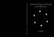
A scanning electron micrograph (JEOL 6300F) <strong>of</strong> a<br />
dried gel is shown in Figure 1, revealing a structure that resembles<br />
a pile <strong>of</strong> egg shells. The material consists <strong>of</strong> a packing<br />
<strong>of</strong> thin spherical shells <strong>of</strong> many different sizes that are<br />
fused together. Many <strong>of</strong> the shells are broken at the side facing<br />
the viewer, but this is presumably the result <strong>of</strong> the fact<br />
that the sample was cut in order to observe the structure inside.<br />
Remarkably, the shells are very smooth and preserve<br />
the spherical droplet shape well. The hydrolysis and condensation<br />
reactions, therefore, did not disrupt the droplet<br />
interfaces. This may have been the result <strong>of</strong> the fact that<br />
hydrolysis and gelation <strong>of</strong> TTIP by water is extremely rapid.<br />
We suspect that immediately upon contact with water a<br />
solid skin is formed on the droplet surface, which prevents<br />
deformation and grows further by diffusion <strong>of</strong> TTIP from<br />
the inside <strong>of</strong> the droplet to the surface. In this way larger<br />
droplets form thicker shells than smaller droplets, as can be<br />
seen in Figure 1.<br />
Fig. 1. SEM image <strong>of</strong> a titania foam made by the addition <strong>of</strong> water to a nonaqueous<br />
emulsion <strong>of</strong> titanium isopropoxide and isooctane.<br />
The thickness, d, <strong>of</strong> the shells can be estimated by assuming<br />
that the titania shell forms at the surface <strong>of</strong> a droplet<br />
with radius R and grows inward. Then Equation 1 can be<br />
derived.<br />
8<br />
>: 1<br />
93<br />
d>;<br />
ˆ 1<br />
R<br />
f r TTIPM titania<br />
r titania M TTIP<br />
(1)<br />
Here, f is the volume fraction <strong>of</strong> alkoxide in the oil, r the<br />
mass density, and M the molecular mass. Taking f = 0.25<br />
and assuming a density <strong>of</strong> 2 g/cm 3 for the (uncalcined) titania<br />
gel we arrive at d/R = 0.012. This means that even a<br />
large droplet <strong>of</strong> 10 mm radius forms a shell <strong>of</strong> only 0.12 mm<br />
thickness. Close inspection <strong>of</strong> the larger shells in Figure 1<br />
shows that this is a good estimate. Even shells less than<br />
1 mm in size are seen to exist, even though they should be<br />
no more than a few nanometers thick.<br />
The larger shells are also seen to contain some grainy<br />
material, which has the form <strong>of</strong> fused globules. Apparently,<br />
in the large shells some <strong>of</strong> the TTIP reacts with water inside<br />
the droplets and not just at the surface. It is unclear<br />
how this material is formed. Possibly, the droplet interfaces<br />
become less stable due to the reaction, which consumes<br />
part <strong>of</strong> the oil droplet and replaces it with titania and isopropanol.<br />
The volume changes involved and the miscibility<br />
<strong>of</strong> isopropanol with the continuous phase would lead to liquid<br />
flow, which could carry some <strong>of</strong> the continuous phase<br />
into the droplets. Considering all these processes it is remarkable<br />
that the overall droplet shapes are conserved<br />
quite well.<br />
It is possible to convert the amorphous titania foams into<br />
crystalline TiO 2 without collapse <strong>of</strong> the shells. Samples<br />
were heated in a furnace for 2 h in air at different temperatures<br />
with a heating rate <strong>of</strong> 10 C/min. The crystal structure<br />
was analyzed by powder X-ray diffraction using Cu Ka radiation<br />
(Philips X'pert-MPD). Scanning electron microscopy<br />
(SEM) images <strong>of</strong> titania foams calcined at 800 and<br />
1000 C are shown in Figure 2. Note that the shell structure<br />
is completely preserved in both samples. However, the<br />
800 C sample (top) consists <strong>of</strong> very smooth shells, whereas<br />
those in the 1000 C sample have become rough due to<br />
grain growth. The X-ray diffraction patterns in Figure 3<br />
show that the titania has crystallized into the anatase structure<br />
after heat treatment at 600 and 800 C. The foam calcined<br />
at 1000 C has largely recrystallized to rutile, but<br />
there remains about 15 % anatase.<br />
After calcination at 600 C the foams had shrunk by<br />
40 % compared to their wet size. Their mass density was<br />
only 0.16 g/cm 3 . If a density <strong>of</strong> 3.84 g/cm 3 is assumed for<br />
anatase, this low density implies a very high porosity <strong>of</strong><br />
96 %. A similarly high porosity was found for titania foams<br />
calcined at 1000 C, which consisted largely <strong>of</strong> rutile (see<br />
Table 1).<br />
<strong>Titania</strong> foams can also be made at a higher volume fraction<br />
<strong>of</strong> droplets. We made emulsions containing an oil volume<br />
fraction <strong>of</strong> 75 %. The oil had the same composition as<br />
before. The resulting foams again consisted <strong>of</strong> thin shells,<br />
but they were packed much more closely than the foams<br />
from the 50 % emulsions, as can be seen in Figure 4. A<br />
mass density <strong>of</strong> 0.25 g/cm 3 was found for these foams, corresponding<br />
to a porosity <strong>of</strong> 93 %.<br />
Nitrogen sorption isotherms were measured at 77 K on<br />
samples made from 50 % and 75 % emulsions and calcined<br />
at different temperatures (Micromeritics ASAP2000). The<br />
isotherms were <strong>of</strong> type IV, indicating the presence <strong>of</strong> mesopores.<br />
Most <strong>of</strong> the nitrogen was adsorbed in pores with a<br />
312 Ó WILEY-VCH Verlag GmbH, D-69469 Weinheim, 1999 0935-9648/99/0403-0312 $ 17.50+.50/0 Adv. Mater. 1999, 11, No. 4
Communications<br />
Fig. 4. SEM image <strong>of</strong> a titania foam made from an emulsion with 75 % v/v<br />
TTIP and isooctane, and 25 % v/v formamide.<br />
diameter smaller than 10 nm. The BET (Brunauer±Emmett±Teller)<br />
specific surface areas are given in Table 1.<br />
These data indicate that the titania shells are mesoporous,<br />
as are all structures formed through sol-gel processes. The<br />
mesopores also provide a pathway by which liquid could be<br />
removed from the foams during the drying stage without<br />
bursting the shells.<br />
Table 1. BET specific surface areas S BET and porosities <strong>of</strong> the titania foams<br />
after calcination.<br />
Fig. 2. SEM images <strong>of</strong> calcined titania foams. Top: Calcined at 800 C, consisting<br />
<strong>of</strong> anatase. Bottom: Calcined at 1000 C, consisting <strong>of</strong> 85 % rutile and<br />
15 % anatase.<br />
Fig. 3. Powder X-ray diffraction results <strong>of</strong> the titania foams calcined at different<br />
temperatures for 2 h, as indicated. The letters A and R are used to label<br />
the peaks corresponding to anatase and rutile, respectively.<br />
The mesoporosity <strong>of</strong> the titania shells can be reduced by<br />
heating with little effect on the macroporosity. The numbers<br />
in Table 1 show that the specific surface area <strong>of</strong> the titania<br />
foams drops rapidly at higher calcination temperatures.<br />
This is due to the removal <strong>of</strong> micro- and mesopores,<br />
which provide most <strong>of</strong> the internal surface area measured<br />
from the BET analysis. The total porosity is hardly affected,<br />
however, because the total porosity is determined mainly<br />
by the macropores (formed by the shells). The macropores<br />
contribute little to the surface area because <strong>of</strong> their relatively<br />
small surface-to-volume ratio. This means that the total<br />
porosity can be set by the composition <strong>of</strong> the emulsion,<br />
but that the specific surface area can be influenced using<br />
the calcination temperature.<br />
In summary, water-sensitive metal alkoxides can be<br />
emulsified in formamide. When these non-aqueous emulsions<br />
are exposed to water, hydrolysis and gelation <strong>of</strong> the<br />
alkoxide give rise to interesting and potentially useful<br />
macroporous materials. In this way we made highly porous<br />
titania with a microstructure consisting <strong>of</strong> very thin spherical<br />
shells. The structure is very robust and is conserved<br />
Adv. Mater. 1999, 11, No. 4 Ó WILEY-VCH Verlag GmbH, D-69469 Weinheim, 1999 0935-9648/99/0403-0313 $ 17.50+.50/0 313
Communications<br />
even when the titania is converted to its crystalline forms<br />
anatase and rutile by calcination.<br />
Received: July 22, 1998<br />
Final version: October 21, 1998<br />
±<br />
[1] A. Imh<strong>of</strong>, D. J. Pine, Nature 1997 389, 948.<br />
[2] A. Imh<strong>of</strong>, D. J. Pine, Adv. Mater. 1998 10, 697.<br />
[3] A. Imh<strong>of</strong>, D. J. Pine, J. Colloid Interface Sci. 1997 192, 368.<br />
[4] T. J. Fitzgerald, V. J. Michaud, A. Mortensen, J. Mater. Sci. 1995 30,<br />
1037.<br />
[5] N. W. Andr<strong>of</strong>f, L. F. Francis, B. V. Velamakanni, AIChE J. 1997 43,<br />
2878.<br />
[6] M. X. Wu, T. Fujiu, G. L. Messing, J. Non-Cryst. Solids 1990 121, 407.<br />
[7] R. L. Downs, M. A. Ebner, W. J. Milner, Sol-Gel Technology for Thin<br />
Films, Fibers, Preforms, Electronics, and Specialty Shapes (Ed: L. C.<br />
Klein), Noyes Publications, Park Ridge, NJ 1988, p. 330.<br />
[8] J. G. Liu, D. L. Wilcox, J. Mater. Res. 1995 10, 84.<br />
Dendrimer-Based Self-Assembled Monolayers<br />
as Resists for Scanning Probe Lithography**<br />
By David C. Tully, Kathryn Wilder, Jean M. J. FrØchet,*<br />
Alexander R. Trimble, and Calvin F. Quate<br />
The feature sizes <strong>of</strong> microelectronic circuitry components<br />
fabricated by current photolithographic processes are<br />
ultimately limited by the wavelength <strong>of</strong> the exposing radiation<br />
used for photochemical transformations. In the pursuit<br />
to develop faster and smaller semiconductor devices, both<br />
new materials and lithographic processes for nan<strong>of</strong>abrication<br />
are currently under exploration by industry and academia<br />
alike. The highest possible resolution is <strong>of</strong> the order <strong>of</strong><br />
the size <strong>of</strong> the individual pixels that compose the image.<br />
Therefore, to obtain patterns with nanometer scale resolution,<br />
a lithographic process should manipulate materials<br />
made from molecules with dimensions no larger than the<br />
desired pixel size.<br />
We are currently exploring the use <strong>of</strong> dendrimer-based<br />
monolayers as resists for scanning probe lithography<br />
(SPL). The well-characterized globular and monodisperse<br />
properties <strong>of</strong> dendrimers make them ideally suited for selfassembly<br />
on a surface. [1±4] Due to their compact size, the<br />
ultra-thin films formed from dendrimers have a thickness<br />
much less than can be obtained by spin-coating ordinary<br />
linear polymers. In addition, we have observed that the<br />
dendritic monolayers are more stable than the analogous<br />
monolayers consisting <strong>of</strong> low molecular weight alkylsilanes.<br />
This may be due, in part, to the polymeric and dense nature<br />
<strong>of</strong> dendrimers, resulting in better protection <strong>of</strong> the anchoring<br />
group.<br />
±<br />
[*] Pr<strong>of</strong>. J. M. J. FrØchet, D. C. Tully, A. R. Trimble<br />
Department <strong>of</strong> Chemistry, University <strong>of</strong> California<br />
Berkeley, CA 94720-1460 (USA)<br />
Pr<strong>of</strong>. C. F. Quate, K. Wilder<br />
E. L. Ginzton Laboratory, Stanford University<br />
Stanford, CA 94305-4085 (USA)<br />
[**] This research was sponsored by the Semiconductor Research Corporation<br />
(SRC contract 96-LC-460) and the Defense Advanced Research<br />
Projects Agency (DARPA grant MDA972-97-1-0010).<br />
The scanning probe microscope (SPM) has recently been<br />
shown to be a versatile tool for nanolithography. The SPM<br />
may be used for the anodization <strong>of</strong> passivated metal surfaces,<br />
[5±12] or it can act as a low energy electron source for<br />
patterning organic polymer thin films. [13±16] The scanning<br />
probe has also been used to pattern both organosilane [17]<br />
and alkanethiolate [18] monolayers on silicon and gold, respectively.<br />
We have been investigating the possibility <strong>of</strong><br />
using ultra-thin polymeric films, such as dendrimer monolayers,<br />
as resists for SPL. Such resists might be attractive<br />
for SPL since a post-exposure wet development step would<br />
not be required prior to etching.<br />
We have investigated the properties <strong>of</strong> monolayers and<br />
ultra-thin films formed from poly(benzylether) dendrimers,<br />
[19,20] terminated with both benzyl and tert-butyldiphenylsilyl<br />
ether groups (Fig. 1), because <strong>of</strong> their relative ease<br />
<strong>of</strong> preparation and derivatization. We report here our studies<br />
on dendritic monolayer formation via covalent attachment<br />
to a silicon substrate and the lithographic patterning<br />
<strong>of</strong> these monolayers using SPL.<br />
Fig. 1. Structures <strong>of</strong> two poly(benzylether) dendrimers, terminated with<br />
both benzyl and tert-butyldiphenylsilyl ether groups.<br />
Both the benzyl ether terminated dendrons [20] (1a) and<br />
the silyl ether terminated dendrons [21] (1b) were prepared<br />
according to previously reported procedures. For the covalent<br />
attachment to the silicon wafer surface, the benzylic alcohol<br />
functionality <strong>of</strong> the dendrons was first acylated with<br />
10-undecenoyl chloride to give esters 2a,b (Scheme 1). Platinum-catalyzed<br />
hydrosilylation <strong>of</strong> the terminal olefin with<br />
either mono- or tri-chlorosilanes using Karstedt's catalyst<br />
afforded the corresponding chlorosilanes 3a±d in quantitative<br />
yields. Polished, n-type Si(100) wafers were cleaned<br />
and surface oxidized prior to use by immersion in a piranha<br />
bath for 30 min at 120 C. The self-assembled monolayers<br />
were prepared by immersing the wafers in a solution <strong>of</strong> the<br />
appropriate silyl chloride (5 mM) in freshly distilled toluene<br />
for 48 h.<br />
The covalently bound dendrimer monolayers (Fig. 2)<br />
were characterized by contact angle goniometry using the<br />
314 Ó WILEY-VCH Verlag GmbH, D-69469 Weinheim, 1999 0935-9648/99/0403-0314 $ 17.50+.50/0 Adv. Mater. 1999, 11, No. 4