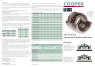
US Split Tapered Bearings mini Catalogue - Cooper Bearings
US Split Tapered Bearings mini Catalogue - Cooper Bearings
US Split Tapered Bearings mini Catalogue - Cooper Bearings

You also want an ePaper? Increase the reach of your titles
YUMPU automatically turns print PDFs into web optimized ePapers that Google loves.
T e c h n<br />
i c a l<br />
I n f o r m at i o n<br />
75mm to 180mm<br />
split tapered BEARINGs
introduction<br />
The <strong>Cooper</strong> split tapered bearing is intended for the ‘fixed’<br />
bearing position of shafts where there is both radial and axial<br />
loading and our ‘GR’ cylindrical roller bearing is unsuitable.<br />
It is constructed with two opposed rows of rollers to take<br />
axial loading in either direction, and is intended to be used with<br />
‘expansion’ type bearings in all other positions on the shaft.<br />
<strong>Cooper</strong> split tapered roller bearings are generally mounted in a<br />
‘cartridge’ in a similar way to <strong>Cooper</strong> cylindrical roller bearings.<br />
This is a spherically-machined inner housing that can be fitted<br />
into a number of types of outer housing.<br />
The spherical seat between the cartridge and the outer housing<br />
accommodates misalignment between the shaft and mounting<br />
structure.<br />
The cartridge also houses the seals. This ensures that the seals<br />
are maintained concentric to the shaft, even if there is significant<br />
misalignment of the shaft relative to the outer housing.<br />
Cartridges for tapered bearings are fitted with a hole<br />
in communication with the outer race, for fitment of a<br />
temperature element, as standard. The standard hole position<br />
is in the end face of the cartridge. The proximity of this hole<br />
to the shaft means that if the temperature element is of the<br />
headed type, generally it will need to have a cranked probe.<br />
Alternative hole positions are possible, including radial holes<br />
requiring additional holes in the outer housing.<br />
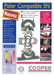
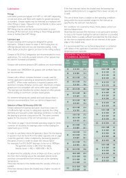
Outer Housings<br />
Pedestal Cap<br />
<strong>Tapered</strong> bearing in cartridge<br />
As the cartridge spherical seat diameters are common to the<br />
seats for <strong>Cooper</strong> cylindrical bearings, the bearing and cartridge<br />
unit can be fitted in a wide variety of existing housing designs.<br />
However, the two types most commonly used are the pedestal<br />
(or ‘pillow block’) and flange.<br />
Pedestal (or ‘pillow block’)<br />
Cartridge<br />
Cage and rollers<br />
Outer race<br />
Pedestal<br />
Base<br />
Clamping<br />
rings<br />
Inner race<br />
Seals (various<br />
options<br />
available)<br />
Shaft<br />
Flange<br />
Ductile iron pillow blocks and flanges are offered as standard<br />
with these bearings. Please confirm load capacities of housings<br />
with our technical department before finalising designs.
75mm to 180mm<br />
<strong>Split</strong> tapered BEARINGs<br />
Bulkhead sealing<br />
It is often found economical to combine a bearing and bulkhead<br />
seal into one unit. This reduces the number of individual<br />
units required, and prevents problems with shaft eccentricity<br />
sometimes encountered at the bulkhead seal when it is separated<br />
from the bearing.<br />
Generally, a specially adapted flange mounting is used and the<br />
bearing is fitted with SRSRP seals (see page 6). Generally, the<br />
flange incorporates additional sealing to the cartridge seating, and<br />
may include sealing on the mounting face (‘backface’).<br />
Where the shaft surface speed is too high for standard SRSRP<br />
seals, an alternative high speed version is available, or alternative<br />
seal types can be used if a moderate leakage of water is<br />
permitted through the bearing in an emergency.<br />
Sealing to flange mounting face (“BFS”)<br />
Sealing to swivel seating (“SSE”)<br />
SRSRP Seal<br />
Combined bearing and bulkhead seal<br />
Bearing Selection<br />
Bearing ratings for dynamic radial capacity (Cr) and static radial<br />
capacity (Cor) shown in this leaflet are in accordance with ISO<br />
281-1990 and ISO 76-1987 respectively.<br />
Radial and axial loads must be considered together as combined<br />
‘equivalent loads’, as explained below. Generally, maximum<br />
instantaneous loading is governed by housing strength rather<br />
than bearing static capacity.<br />
Dynamic rating<br />
Expected bearing life is calculated by the following equation:<br />
L10 = [Cr/(P x fd)] (10/3)<br />
where:<br />
L10 = expected life of 90% of similar bearings<br />
under similar operating conditions<br />
Cr = radial dynamic rating<br />
P = equivalent dynamic load<br />
fd = dynamic or service factor, generally from<br />
1 for steady loading to 3.5 for heavy shock,<br />
reciprocation or vibration<br />
The dynamic equivalent load is calculated as follows:<br />
when F a /F r ≤e : P = F r + Y 1 F a<br />
when F a /F r >e : P = 0.67F r + Y 2 F a<br />
where:<br />
F r = applied radial load<br />
F a = applied axial load<br />
and calculation factors Y 1 , Y 2 and e are given in the product data<br />
tables.<br />
Life calculation with multiple load conditions<br />
Where varying loads are experienced in operation, using the<br />
maximum load condition may lead to an unrealistically low<br />
calculated life. For n load conditions constituting the full load<br />
cycle (at constant speed), an overall dynamic equivalent load may<br />
be calculated as follows:<br />
i=n<br />
0.3<br />
P = [ΣP (10/3) i p i ]<br />
where:<br />
P i<br />
p i<br />
i=1<br />
= dynamic equivalent load under load<br />
condition i<br />
= proportion of time load condition i is<br />
applicable<br />
Where the load is continuously variable it may be broken down<br />
into a discrete approximation to the actual load cycle.<br />
Minimum loading<br />
In order to avoid excessive skidding of the rollers, sufficient<br />
loading must be applied to the bearing, as follows:<br />
P ≥ 0.01Cr<br />
2
Static rating<br />
The static load rating is defined as the load at which a contact<br />
stress of 4GPa occurs at the centre of the most heavily loaded<br />
contact, and at which a permanent deformation of 0.0001 times<br />
the roller diameter is sustained at the location of the contact.<br />
This has been found to not cause significant deterioration in<br />
bearing performance under typical operating conditions.<br />
The suitability of a bearing for sustaining a specified static (or<br />
instantaneous maximum) load is determined as follows:<br />
where:<br />
C or ≥ S o x P o<br />
C or<br />
S o<br />
P o<br />
= static radial capacity<br />
= static safety factor<br />
= F r + Y o F a where calculation factor Y o is<br />
given in the product data tables.<br />
Standard shaft design<br />
3<br />
Temperature Characteristics<br />
Standard bearings can operate at between -20°C and 100°C.<br />
Operation outside this range is possible but may require special<br />
treatment of bearings parts – please contact our technical<br />
department.<br />
The difference in temperature between the shaft and housing<br />
should not exceed 40°C.<br />
Standard shaft design with ATL seals<br />
(where applicable)<br />
Mounting Arrangements<br />
General arrangements<br />
In order to provide accurate and positive location of the<br />
inner race on the shaft, these bearings are generally mounted<br />
on a recessed journal, and the standard cartridges and seals<br />
are designed to suit this arrangement. As the bearings are<br />
completely split to the shaft, there is no need to provide separate<br />
collars to create this recess – it can be machined directly into<br />
a solid shaft. Also, there is no need to design the surrounding<br />
parts to allow for axial assembly of the bearing and it can be<br />
fitted between integral shaft flanges, cranks, mounted parts and<br />
assemblies etc.<br />
Usually, the shaft is carried through the end of the cartridge at<br />
the diameter of the journal abutment, with the seals operating<br />
on this larger diameter. If alu<strong>mini</strong>um triple labyrinth (ATL) seals<br />
are to be used, on some sizes the diameter of the cartridge end<br />
bore would be excessive with this arrangement, so the shaft has<br />
only narrow shoulders abutting the inner race, with the seals<br />
operating on a diameter equal to the journal diameter.<br />
Shaft design for ATL seals<br />
where standard not applicable<br />
If the journal and the portions of the shaft under the seals<br />
are required to be of the same diameter and integral abutting<br />
shoulders are not possible, alternatives are to use spirally<br />
wound retaining rings mounted in grooves in the shaft, or<br />
special split location collars (usually requiring special cartridges<br />
to accommodate them). It may be possible to locate the inner<br />
race on the shaft using only the clamping effort provided by the<br />
inner race clamping rings, without auxiliary location features, but<br />
this should only be done in consultation with <strong>Cooper</strong> technical<br />
department.
75mm to 180mm<br />
<strong>Split</strong> tapered BEARINGs<br />
Use of retaining rings<br />
to locate inner race<br />
All arrangements not conforming to the standard designs<br />
illustrated in the product data tables will require confirmation of<br />
dimensions and part codes for the cartridges and seals.<br />
Use of split collars<br />
to locate inner race<br />
Alternative abutment diameters can be accommodated using<br />
alternative seals and housing end bores. If larger shaft fillet radii<br />
are required, we can supply bearings with extra large chamfers to<br />
the inner race bores.<br />
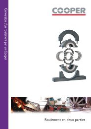
Shaft tolerance<br />
Shaft tolerances are as illustrated opposite. The tolerance on<br />
roundness and parallelism of the journal is IT6.<br />
A tolerance of h9 is applicable to the seal seating area even<br />
when it is the same nominal diameter as the journal.<br />
4<br />
diameter<br />
over 50 80 120 180<br />
(mm)<br />
Tolerance<br />
band (to<br />
BS 4500)<br />
up to and incl. 80 120 180 250<br />
h6<br />
+0 +0 +0 +0<br />
-19 -22 -25 -29<br />
h9<br />
+0 +0 +0 +0<br />
-74 -87 -100 -115<br />
C +0.340<br />
+0.120<br />
d (h6)<br />
A (h9)<br />
IT6 19 22 25 29<br />
max. shaft fillet radii:<br />
75mm bore size: 1.2mm<br />
all others: 2.3mm<br />
Standard shaft design
Sealing<br />
Standard <strong>Cooper</strong> housed tapered bearing units incorporate<br />
a cartridge with spherical seating, which maintains the seals<br />
concentric with the shaft under misaligned conditions.<br />
Compared to units where the misalignment is taken up between<br />
the bearing and outside housing, closer running clearances<br />
(in non-contact seals) or more even seal pressure can be<br />
maintained.<br />
Grease groove (LAB)<br />
Supplied as standard. Suitable for high or slow speed operations.<br />
Particularly successful on marine applications when conditions<br />
are clean and dry.<br />
<strong>Cooper</strong> offer a wide range of seals, together suitable for most<br />
environments. Some of the more common options are shown<br />
below. Further types, or combinations of seals, are possible.<br />
Different cartridges are required depending upon seal type.<br />
Felt, high temperature packing and single lip (SRS) seals all use a<br />
common cartridge.<br />
If felt seal are specified, these are supplied with the cartridge<br />
(although they can still be ordered separately). Other seal types<br />
must be ordered separately (i.e. they are not automatically<br />
supplied with the cartridge).<br />
Temperature limits<br />
bearing maximum<br />
5<br />
Maximum operating speeds of the various types of seals are<br />
specified in dn(mm). To calculate the speed in dn(mm) multiply<br />
the shaft speed (in rpm) by the diameter of the seal seating area<br />
(in mm).<br />
Maximum speed<br />
Shaft surface finish<br />
(max. roughness)<br />
bearing maximum<br />
3.2µm Ra<br />
Felt (F)<br />
Suitable for dry, dusty conditions.<br />
Temperature limits -70°C to 100°C<br />
Maximum speed<br />
Shaft surface finish<br />
(max. roughness)<br />
150,000 dn(mm)<br />
1.6µm Ra
75mm to 180mm<br />
<strong>Split</strong> tapered BEARINGs<br />
High temperature packing (HTP)<br />
A direct replacement for felt in high temperature applications, or<br />
for use in fire-resistant bulkheads.<br />
Synthetic rubber single lip (SRS)<br />
High temperature version (SRS HT)<br />
Low temperature version (SRS LT)<br />
Suitable for wet but not submerged conditions. Can be used for<br />
improved lubricant retention by mounting lip inwards.<br />
Temperature limits -70°C to 260°C<br />
Maximum speed<br />
Shaft surface finish<br />
(max. roughness)<br />
150,000 dn(mm)<br />
0.8µm Ra<br />
Temperature limits<br />
Maximum speed<br />
Shaft surface finish<br />
(max. roughness)<br />
SRS<br />
SRS HT<br />
SRS LT<br />
150,000 dn(mm)<br />
0.8µm Ra<br />
-20°C to 100°C<br />
-20°C to 175°C<br />
-60°C to 100°C<br />
6<br />
Alu<strong>mini</strong>um triple labyrinth (ATL)<br />
High temperature version (ATL HT)<br />
Low temperature version (ATL LT)<br />
Machined alu<strong>mini</strong>um bodied triple labyrinth seal for high speed<br />
and general applications.<br />
Spring-loaded single lip with retaining plate (SRSRP)<br />
High pressure version (SRSRP 40M)<br />
Suitable for severe splash or completely submerged conditions.<br />
The standard version is suitable for up to 2m of water.<br />
The high pressure version is suitable for up to 40m of water.<br />
Temperature limits<br />
Maximum speed<br />
Shaft surface finish<br />
(max. roughness)<br />
ATL<br />
ATL HT<br />
ATL LT<br />
bearing maximum<br />
3.2µm Ra<br />
-20°C to 100°C<br />
-20°C to 175°C<br />
-60°C to 100°C<br />
Temperature limits -20°C to 100°C<br />
Maximum speed<br />
Shaft surface finish<br />
(max. roughness)<br />
150,000 dn(mm)<br />
0.4µm Ra
BEARING DATA<br />
B<br />
C<br />
D<br />
d<br />
7<br />
bearing data<br />
Shaft<br />
Diameter<br />
d (mm)<br />
Reference<br />
Cr<br />
(kN)<br />
Bearing Ratings Calculation Factors Principal Dimensions<br />
Cor<br />
(kN)<br />
Max. Speed<br />
(rpm)<br />
Y1 Y2 e Yo<br />
75 1DTB75M 143 208 3410 1.27 1.89 0.53 1.24 135 82.6 35 4.0<br />
80 1DTB80M 152 232 3200 1.20 1.79 0.56 1.18 145 85 35 4.6<br />
90 1DTB90M 160 254 2840 1.11 1.65 0.61 1.08 150 85 35 4.7<br />
100 1DTB100M 235 379 2560 1.17 1.75 0.58 1.15 175 100 40 8.3<br />
110 1DTB110M 282 504 2330 1.05 1.56 0.64 1.02 190 110 48 11.4<br />
120 1DTB120M 295 544 2130 1.00 1.49 0.68 0.98 200 110 48 11.9<br />
140 1DTB140M 296 555 1830 1.27 1.90 0.53 1.24 215 110 45 12.2<br />
160 1DTB160M 350 670 1600 1.34 1.99 0.50 1.31 240 110 45 14.8<br />
180 1DTB180M 358 716 1420 1.21 1.80 0.56 1.18 265 110 45 17.0<br />
D<br />
(mm)<br />
C<br />
(mm)<br />
B<br />
(mm)<br />
Mass<br />
(Kg)
cartridge data<br />
L<br />
L1<br />
L1<br />
L2<br />
J<br />
w (max.)<br />
G<br />
A<br />
d<br />
A<br />
Type 1<br />
Type 2<br />
hole for temperature element<br />
drilled Ø6.2 thro’ and tapped G1/8 x 12 deep<br />
8<br />
cartridge data<br />
abutment<br />
Cartridge for<br />
LAB seals<br />
References (1)<br />
Cartridge for<br />
ATL seals<br />
Shaft<br />
type<br />
(2)<br />
G<br />
(mm)<br />
J<br />
(mm)<br />
Principal Dimensions<br />
1DTC75M-80M 1DTC05 2 177.80 50 138 140 162 11.8 80 7<br />
1DTC80M-90M 1DTC06-80M 1 203.20 50 140 142 164 15.1 90 -<br />
1DTC90M-100M 1DTC06-90M 2 203.20 50 146 148 170 13.5 100 7.5<br />
1DTC100M-110M 1DTC07 2 231.78 64 170 172 202 20.1 110 7.5<br />
1DTC110M-120M 1DTC08-110M 1 266.70 76 178 180 210 29.8 120 -<br />
1DTC120M-130M 1DTC08-120M 1 266.70 76 178 180 210 26.5 130 -<br />
1DTC140M-150M 1DTC09 2 279.40 76 190 192 222 31.2 150 10<br />
1DTC160M-170M 1DTC11 2 311.15 76 200 202 232 47.0 170 10<br />
1DTC180M-195M 1DTC31 2 336.55 95 200 206 232 42.5 195 9<br />
L<br />
(mm)<br />
L1<br />
(mm)<br />
L2<br />
(mm)<br />
Mass<br />
(Kg)<br />
A<br />
(mm)<br />
w (2)<br />
(mm)<br />
1) For other seal types add seal type designation to end of reference for cartridge for LAB seals<br />
e.g.120mm cartridge with SRSRP seals: 1DTC120M-130M SRSRP<br />
2) Only applicable when fitted with TL seals. All other seal types run on shaft diameter A.
PEDESTALS<br />
O<br />
O<br />
S<br />
P<br />
H<br />
T<br />
9<br />
Note: Pedestals with solid bases also available.<br />
R<br />
N<br />
R<br />
N<br />
pedestal data<br />
Shaft<br />
Diameter<br />
d (mm)<br />
Bearing<br />
Reference<br />
Reference (1)<br />
(pedestal only)<br />
H<br />
(mm)<br />
Min.<br />
(mm)<br />
R<br />
Max.<br />
(mm)<br />
S<br />
(mm)<br />
No.<br />
Bolts<br />
Size<br />
N<br />
(mm)<br />
O<br />
(mm)<br />
P<br />
(mm)<br />
T<br />
(mm)<br />
Mass<br />
(pedestal only)<br />
(Kg)<br />
75 1DTB75M PN05 112 312 328 - 2 M24 380 90 44 252 13.3<br />
80 1DTB80M PN06 125 342 366 - 2 M24 420 102 52 272 14.7<br />
90 1DTB90M PN06 125 342 366 - 2 M24 420 102 52 272 14.7<br />
100 1DTB100M PN07 143 374 410 - 2 M24 466 120 60 314 20.6<br />
110 1DTB110M PN08 162 438 462 120 4 M24 508 178 38 372 43.3<br />
120 1DTB120M PN08 162 438 462 120 4 M24 508 178 38 372 43.3<br />
140 1DTB140M PN09 181 470 494 120 4 M24 558 178 41 405 52<br />
160 1DTB160M PN11 213 356 380 114 4 M24 508 178 32 430 53<br />
180 1DTB180M PN31 210 546 570 128 4 M24 636 204 50 470 83<br />
1) For lubrication point to spherical seating add ‘SLUB’ to reference, e.g. PN08 SLUB
FLANGES<br />
R PCD,<br />
holes equally spaced<br />
P<br />
L<br />
V<br />
T<br />
N<br />
d<br />
H<br />
10<br />
flange bearing data<br />
Shaft<br />
Diameter<br />
d (mm)<br />
Bearing<br />
Reference<br />
Reference (1)<br />
(flange only)<br />
T (2)<br />
(mm)<br />
Bolt<br />
Size<br />
R<br />
(mm)<br />
P<br />
(mm)<br />
H<br />
(mm)<br />
N (3)<br />
(mm)<br />
V (3)<br />
(mm)<br />
Mass<br />
(flange only)<br />
(Kg)<br />
75 1DTB75M FN05 330 M16 274 19 79 215.90 3 19.4<br />
80 1DTB80M FN06 356 M16 302 19 86 244.48 3 22.0<br />
90 1DTB90M FN06 356 M16 302 19 86 244.48 3 22.0<br />
100 1DTB100M FN07 382 M16 334 22 92 276.23 3 26.6<br />
110 1DTB110M FN08 432 M24 374 22 98 314.33 3 34.9<br />
120 1DTB120M FN08 432 M24 374 22 98 314.33 3 34.9<br />
140 1DTB140M FN09 444 M24 384 25 98 317.50 3 40.8<br />
160 1DTB160M FN11 496 M24 426 25 105 352.43 3 58<br />
180 1DTB180M FN31 534 M24 466 25 124 393.70 3 81<br />
1) For lubrication point to spherical seating add ‘SLUB’ to reference, e.g. FN08 SLUB<br />
2) Dimension shown is as-cast dimension. Depending upon manufacturing method used, flanges supplied may be machined 5mm smaller<br />
3) Dimensions shown are for locating spigot for mounting flange on to. Diameter tolerance of locating spigot: f8<br />
Where SRSRP seals are used cartridge assembly may protrude into bulkhead. Consult <strong>Cooper</strong> for <strong>mini</strong>mum bulkhead aperture size.
Lubrication<br />
Fittings<br />
Lubrication points are tapped 1/8”NPT and fitted with nipples<br />
for grease lubrication as standard. Grease nipples may be<br />
removed and replaced with other fittings or pipes. Pipework<br />
must be flexible to allow the swivel cartridge to function<br />
correctly.<br />
BSP fittings may be used, but care must be taken to avoid<br />
blocking off the lubricant cross-drilling as these fittings generally<br />
screw in further than NPT fittings.<br />
Lubricant type<br />
<strong>Cooper</strong> tapered bearings and housings are designed for grease<br />
lubrication. Grease is easier to retain in the housing than oil,<br />
offering reduced lubricant loss and improved sealing. It also<br />
offers better protection against corrosion to the rolling surfaces.<br />
Greases of NLGI No.2 designation are recommended for most<br />
applications. For centrally pumped systems a No.1 grease may<br />
be used for increased ‘pumpability’.<br />
Greases with extreme pressure (EP) additives are recommended.<br />
11 Grease with a lithium complex thickener is usually used for<br />
normal applications operating at temperatures between 0°C<br />
and 80°C. When water resistance is required a grease with<br />
alu<strong>mini</strong>um complex thickener can be used. Alu<strong>mini</strong>um complex<br />
greases are not compatible with some other types of grease.<br />
The bearing must therefore be solvent cleaned of other greases<br />
before adding an alu<strong>mini</strong>um complex based grease.<br />
For extreme temperatures, speeds and loads always obtain a<br />
lubricant recommendation from our technical department.<br />
Selection of base oil viscosity<br />
In order for the bearing to have a long service life the grease<br />
selected for bearing lubrication must have a base oil of sufficiently<br />
high viscosity to adequately separate the rolling elements and<br />
race parts under operating conditions.<br />
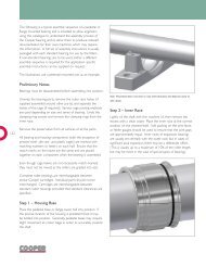
The charts in Figure 2 show the recommended operating ranges<br />
for three common oil viscosities, for bearings under normal<br />
loading (up to Cr/10).<br />
To use these charts, find the ‘geometry factor’ for the bearing<br />
from the table below and multiply this by the bearing speed in<br />
thousands of rpm to obtain the velocity factor.<br />
geometry factor<br />
Shaft Diameter<br />
d (mm)<br />
Bearing<br />
Reference<br />
Geometry<br />
factor<br />
75 1DTB75M 63<br />
80 1DTB80M 69<br />
90 1DTB90M 78<br />
100 1DTB100M 96<br />
110 1DTB110M 110<br />
120 1DTB120M 118<br />
140 1DTB140M 144<br />
160 1DTB160M 169<br />
180 1DTB180M 196<br />
For example, if a 100mm bearing is to be run at 1200rpm:<br />
The geometry factor is 96 from the table<br />
Velocity factor = 96 x (1200/1000) = 115.2<br />
To determine the suitability of one of these oils, draw a vertical<br />
line from the horizontal axis at the calculated velocity factor, and<br />
draw a horizontal line from the vertical axis at the operating<br />
temperature.<br />
If the lines intersect in the shaded area the viscosity of oil is<br />
suitable. If the lines intersect above the shaded area a higher<br />
viscosity oil is required. If the lines intersect below the shaded<br />
area the bearing may operate satisfactorily but it is suggested that<br />
a grease with a lower viscosity base oil is used.<br />
The use of these charts is subject to the operating conditions<br />
being within the recommended ranges for the lubricant as<br />
specified by the lubricant manufacturer.<br />
For conditions not covered by these charts please contact our<br />
technical department.<br />
Note that the lubrication film thickness is not particularly<br />
sensitive to load, so for heavier loading the lubricant selection as<br />
provided by these charts is usually sufficient provided that the<br />
lines drawn on the chart as explained above do not intersect at<br />
the upper edge of the shaded area.
75mm to 180mm<br />
<strong>Split</strong> tapered BEARINGs<br />
Figure 2<br />
<strong>Cooper</strong> Bearing recommended speed<br />
and temperature range for VG 150<br />
grease and oils<br />
Temperature (°C)<br />
120<br />
110<br />
100<br />
90<br />
80<br />
70<br />
60<br />
50<br />
40<br />
30<br />
20<br />
10<br />
0<br />
-10<br />
-20<br />
0 20 40 60 80 100 120 140 160 180 200 220 240 260 280 300<br />
Velocity factor = geometry factor X rpm in thousands<br />
<strong>Cooper</strong> Bearing recommended speed<br />
and temperature range for VG 220<br />
grease and oils<br />
Temperature (°C)<br />
120<br />
110<br />
100<br />
90<br />
80<br />
70<br />
60<br />
50<br />
40<br />
30<br />
20<br />
10<br />
0<br />
-10<br />
-20<br />
0 20 40 60 80 100 120 140 160 180 200 220 240 260 280 300<br />
12<br />
Velocity factor = geometry factor X rpm in thousands<br />
<strong>Cooper</strong> Bearing recommended speed<br />
and temperature range for VG 460<br />
grease and oils<br />
Temperature (°C)<br />
120<br />
110<br />
100<br />
90<br />
80<br />
70<br />
60<br />
50<br />
40<br />
30<br />
20<br />
10<br />
0<br />
-10<br />
-20<br />
0 20 40 60 80 100 120 140 160 180 200 220 240 260 280 300<br />
Velocity factor = geometry factor X rpm in thousands
Grease quantity for initial lubrication<br />
The quantity of grease required on initial lubrication is dependent<br />
upon operating speed and temperature.<br />
If the operating temperature is below 80°C the quantity of<br />
grease may be determined directly according to the bearing<br />
reference and operating speed from the table below. If the<br />
operating temperature is above 80°C a 25% pack of grease<br />
should be used regardless of operating speed (refer to the right<br />
hand column of the table).<br />
With a ‘full pack’ of grease the space within the housing (i.e.<br />
surrounding the bearing components) in the assembled unit is<br />
completely filled with grease.<br />
The table assumes normal density grease (about 0.85 g/cm 3 ).<br />
Routine Greasing<br />
Relubricate the bearing weekly or every 150 hours of operation.<br />
Sizes up to and including 120mm: Use 2ml of fresh grease.<br />
Sizes over 120mm: Use 4ml of fresh grease.<br />
Note that 2ml is approximately 1 shot from a conventional sidelever<br />
grease gun.<br />
Automatic lubrication systems should be metered to deliver<br />
grease at an average rate equivalent to the routine greasing<br />
periods and quantities specified.<br />
If it can be done safely, the bearing should be re-greased as it<br />
rotates to help distribute the grease.<br />
Do not mix different types of grease in the bearing. Excessive<br />
quantities of lubricant should not be used, particularly at high<br />
speeds, as this may result in excessive churning and overheating.<br />
Initial lubricant quantities<br />
Shaft<br />
Diameter<br />
d (mm)<br />
Bearing<br />
Reference<br />
Speed<br />
(rpm)<br />
up to<br />
Grease<br />
(full pack)<br />
(Kg)<br />
Speed (rpm)<br />
Grease<br />
(75% full<br />
pack) (Kg)<br />
Speed (rpm)<br />
Grease<br />
(50% full<br />
pack) (Kg)<br />
Speed (rpm)<br />
from to from to from to<br />
Grease<br />
(33% full<br />
pack) (Kg)<br />
Speed<br />
(rpm)<br />
over<br />
Grease<br />
(25% full<br />
pack) (Kg)<br />
75 1DTB75M 667 0.19 667 1333 0.14 1333 2000 0.10 2000 2667 0.06 2667 0.05<br />
80 1DTB80M 625 0.23 625 1250 0.17 1250 1875 0.12 1875 2500 0.08 2500 0.06<br />
13<br />
90 1DTB90M 556 0.25 556 1111 0.19 1111 1667 0.12 1667 2222 0.08 2222 0.06<br />
100 1DTB100M 500 0.41 500 1000 0.31 1000 1500 0.20 1500 2000 0.13 2000 0.10<br />
110 1DTB110M 455 0.44 455 909 0.33 909 1364 0.22 1364 1818 0.14 1818 0.11<br />
120 1DTB120M 417 0.50 417 833 0.38 833 1250 0.25 1250 1667 0.17 1667 0.13<br />
140 1DTB140M 357 0.65 357 714 0.48 714 1071 0.32 1071 1429 0.21 1429 0.16<br />
160 1DTB160M 313 0.63 313 625 0.47 625 938 0.32 938 1250 0.21 1250 0.16<br />
180 1DTB180M 278 0.77 278 556 0.58 556 833 0.39 833 1111 0.25 1111 0.19<br />
Frequency Data<br />
Bearing frequency data are included in this document for two<br />
purposes:<br />
• to allow machine designers to check excitation frequencies<br />
against resonant frequencies in the machine,<br />
• to allow correct input into condition monitoring equipment<br />
that uses these data.<br />
A roller bearing will excite vibrations at certain frequencies related<br />
to the number, size and pitch circle diameter of the rollers. To<br />
some extent this excitation is present even with new bearings in<br />
perfect condition, as the load is carried on discrete, elastic, rolling<br />
elements which are constantly changing in angular position.<br />
The table at the top of the page opposite indicates the frequencies<br />
of bearing parts per shaft revolution, which can be used to<br />
calculate excitation frequencies directly by multiplying the tabulated<br />
frequencies by the shaft speed.<br />
The frequencies listed are explained as follows:<br />
‘Cage’ – the frequency at which a point on the cage enters and<br />
leaves the loaded zone of the bearing<br />
‘Roller’ – the frequency at which a point on a given roller passes<br />
into contact with either the inner or outer race<br />
‘Outer’ – the frequency at which a point on the outer race<br />
comes into contact with successive rollers<br />
‘Inner’ – the frequency at which a point on the inner race comes<br />
into contact with successive rollers<br />
The table also lists the pitch circle diameters, number of rollers<br />
and contact angle for use with condition monitoring equipment<br />
that accepts this information.
75mm to 180mm<br />
<strong>Split</strong> tapered BEARINGs<br />
Bearing Frequencies<br />
Shaft<br />
Diameter<br />
(mm)<br />
Bearing<br />
Reference<br />
Part Frequencies (per shaft rev.)<br />
Cage Roller Outer Inner<br />
PCD<br />
(mm)<br />
Roller Details<br />
No.<br />
Diameter<br />
(mm)<br />
Contact<br />
angle (°)<br />
75 1DTB75M 0.445 4.264 8.006 9.994 102.6 18 11.95 17.50<br />
80 1DTB80M 0.448 4.507 8.959 11.041 108.2 20 11.95 18.50<br />
90 1DTB90M 0.453 4.898 9.955 12.045 117.4 22 11.95 20.13<br />
100 1DTB100M 0.449 4.627 9.888 12.112 136.0 22 14.63 19.00<br />
110 1DTB110M 0.455 5.167 10.926 13.074 147.9 24 14.29 21.25<br />
120 1DTB120M 0.457 5.404 11.895 14.105 154.5 26 14.29 22.25<br />
140 1DTB140M 0.461 6.022 12.901 15.099 176.4 28 14.62 18.00<br />
160 1DTB160M 0.461 6.145 12.918 15.082 196.9 28 15.99 17.21<br />
180 1DTB180M 0.465 6.776 13.959 16.041 216.8 30 15.99 19.00<br />
Tightening Torques<br />
The tightening torques for the assembly of the bearings<br />
and housing are given in the following table. All screws are<br />
metric coarse thread, grade 12.9. Full assembly instructions<br />
are provided with each order, and are available separately if<br />
required.<br />
Tightening Torques<br />
14<br />
Shaft<br />
Diameter<br />
(mm)<br />
Bearing<br />
Reference<br />
Clamping ring screw Cartridge joint screw Side screw Pedestal joint screw Flange joint screw<br />
Screw size<br />
Key size<br />
A/F (mm)<br />
Torque<br />
(Nm)<br />
Screw size<br />
Key size<br />
A/F (mm)<br />
Torque<br />
(Nm)<br />
Screw size<br />
Key size<br />
A/F (mm)<br />
Torque<br />
(Nm)<br />
Screw size<br />
Key size<br />
A/F (mm)<br />
Torque<br />
(Nm)<br />
Screw size<br />
Key size<br />
A/F (mm)<br />
75 1DTB75M M5x25 4 8.5 M6x25 5 11 M6x10 3 7.8 M16x65 14 225 M12x55 10 90<br />
80 1DTB80M M5x25 4 8.5 M10x45 8 52.5 M6x10 3 7.8 M16x65 14 225 M16x65 14 225<br />
90 1DTB90M M5x25 4 8.5 M10x45 8 52.5 M6x10 3 7.8 M16x65 14 225 M16x65 14 225<br />
100 1DTB100M M8x30 6 35 M10x45 8 52.5 M6x10 3 7.8 M20x80 17 420 M16x65 14 225<br />
110 1DTB110M M8x30 6 35 M12x55 10 90 M6x10 3 7.8 M20x80 17 420 M20x80 17 420<br />
120 1DTB120M M8x30 6 35 M10x45 8 52.5 M6x10 3 7.8 M20x80 17 420 M20x80 17 420<br />
140 1DTB140M M8x30 6 35 M10x45 8 52.5 M6x10 3 7.8 M20x80 17 420 M20x80 17 420<br />
160 1DTB160M M8x30 6 35 M10x45 8 52.5 M10x16 5 30 M16x65 14 225 M20x100 17 420<br />
180 1DTB180M M8x30 6 35 M10x55 8 52.5 M10x16 5 30 M20x80 17 420 M24x100 19 712<br />
Torque<br />
(Nm)
customer service centres<br />
Germany<br />
<strong>Cooper</strong> Geteilte Rollenlager GmbH.<br />
Postfach 100 423<br />
Oberbenrader Str. 407<br />
47704 Krefeld<br />
GERMANY<br />
Tel: +49 (0) 2151 713 016<br />
Fax: +49 (0) 2151 713 010<br />
Email: <strong>Cooper</strong>salesDE@kaydon.com<br />
COOPER BEARINGs group<br />
<strong>US</strong>A, Canada, Mexico<br />
and Central America<br />
The <strong>Cooper</strong> <strong>Split</strong> Roller Bearing Corp.<br />
5365 Robin Hood Road<br />
Suite B<br />
Norfolk<br />
VA 23513<br />
<strong>US</strong>A.<br />
Tel: +1 (1) 757 460 0925<br />
Fax: +1 (1) 757 464 3067<br />
Email: <strong>Cooper</strong>sales<strong>US</strong>@kaydon.com<br />
UK, Europe, South America, Asia,<br />
Australia and the Middle East<br />
<strong>Cooper</strong> Roller <strong>Bearings</strong> Company Ltd.<br />
Wisbech Road<br />
Kings Lynn<br />
Norfolk<br />
PE30 5JX<br />
United Kingdom<br />
Tel: +44 (0) 1553 763447<br />
Fax: +44 (0) 1553 761113<br />
Email: <strong>Cooper</strong>salesUK@kaydon.com<br />
People’s Republic of China<br />
<strong>Cooper</strong> <strong>Bearings</strong> Group Beijing.<br />
Room 909, Canway Building Tower 1<br />
No 66, Nanlishi Road<br />
Xicheng District<br />
Beijing<br />
PRC 100045<br />
Tel: +86 (0) 10 68080803<br />
+86 (0) 10 68080805<br />
+86 (0) 10 68080806<br />
Fax: +86 (0) 10 68080801<br />
Email: <strong>Cooper</strong>salesCN@kaydon.com<br />
Brazil<br />
<strong>Cooper</strong> do Brasil Ltda.<br />
Caixa Postal 66.105<br />
CEP 05.314-970<br />
Brasil<br />
Tel: +55 (0) 11 3022 3706<br />
Tel: +55 (0) 11 9156 2500<br />
Email: <strong>Cooper</strong>salesBR@kaydon.com<br />
India<br />
<strong>Cooper</strong> Roller <strong>Bearings</strong> Company Ltd.<br />
Wisbech Road<br />
Kings Lynn<br />
Norfolk<br />
PE30 5JX<br />
United Kingdom<br />
Tel: +91 (0) 9820180089<br />
Email: <strong>Cooper</strong>salesIN@kaydon.com<br />
www.cooperbearings.com<br />
Document code: CPR013_bEng_Aug10