COM-JC - rkc instrument inc.
COM-JC - rkc instrument inc.
COM-JC - rkc instrument inc.

Create successful ePaper yourself
Turn your PDF publications into a flip-book with our unique Google optimized e-Paper software.
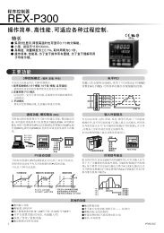
CC-Link Communication<br />
Converter<br />
<strong>COM</strong>-<strong>JC</strong><br />
[For FB100/FB400/FB900]<br />
Instruction Manual<br />
®<br />
RKC INSTRUMENT INC.<br />
IMR01Y06-E5
• CC-Link is a registered trademark of Mitsubishi Electric Co. Ltd.<br />
• Modbus is a registered trademark of Schneider Electric.<br />
• The name of each programmable controller (PLC) means the products of each manufacturer.<br />
• Company names and product names used in this manual are the trademarks or registered trademarks of<br />
the respective companies.<br />
All Rights Reserved, Copyright © 2005, RKC INSTRUMENT INC.
Thank you for purchasing this RKC <strong>instrument</strong>. In order to achieve maximum performance and ensure<br />
proper operation of your new <strong>instrument</strong>, carefully read all the instructions in this manual. Please<br />
place this manual in a convenient location for easy reference.<br />
SYMBOLS<br />
WARNING<br />
CAUTION<br />
!<br />
: This mark indicates precautions that must be taken if there is danger of electric<br />
shock, fire, etc., which could result in loss of life or injury.<br />
: This mark indicates that if these precautions and operating procedures are not<br />
taken, damage to the <strong>instrument</strong> may result.<br />
: This mark indicates that all precautions should be taken for safe usage.<br />
: This mark indicates important information on installation, handling and operating<br />
procedures.<br />
: This mark indicates supplemental information on installation, handling and<br />
operating procedures.<br />
: This mark indicates where additional information may be located.<br />
!<br />
WARNING<br />
• An external protection device must be installed if failure of this <strong>instrument</strong><br />
could result in damage to the <strong>instrument</strong>, equipment or injury to personnel.<br />
• All wiring must be completed before power is turned on to prevent electric<br />
shock, fire or damage to <strong>instrument</strong> and equipment.<br />
• This <strong>instrument</strong> must be used in accordance with the specifications to<br />
prevent fire or damage to <strong>instrument</strong> and equipment.<br />
• This <strong>instrument</strong> is not intended for use in locations subject to flammable or<br />
explosive gases.<br />
• Do not touch high-voltage connections such as power supply terminals, etc.<br />
to avoid electric shock.<br />
• RKC is not responsible if this <strong>instrument</strong> is repaired, modified or<br />
disassembled by other than factory-approved personnel. Malfunction can<br />
occur and warranty is void under these conditions.<br />
IMS01Y06-E5 i-1
CAUTION<br />
• This product is intended for use with industrial machines, test and measuring equipment.<br />
(It is not designed for use with medical equipment and nuclear energy.)<br />
• This is a Class A <strong>instrument</strong>. In a domestic environment, this <strong>instrument</strong> may cause radio<br />
interference, in which case the user may be required to take additional measures.<br />
• This <strong>instrument</strong> is protected from electric shock by reinforced insulation. Provide<br />
reinforced insulation between the wire for the input signal and the wires for <strong>instrument</strong><br />
power supply, source of power and loads.<br />
• Be sure to provide an appropriate surge control circuit respectively for the following:<br />
- If input/output or signal lines within the building are longer than 30 meters.<br />
- If input/output or signal lines leave the building, regardless the length.<br />
• This <strong>instrument</strong> is designed for installation in an enclosed <strong>instrument</strong>ation panel. All<br />
high-voltage connections such as power supply terminals must be enclosed in the<br />
<strong>instrument</strong>ation panel to avoid electric shock by operating personnel.<br />
• All precautions described in this manual should be taken to avoid damage to the<br />
<strong>instrument</strong> or equipment.<br />
• All wiring must be in accordance with local codes and regulations.<br />
• All wiring must be completed before power is turned on to prevent electric shock,<br />
<strong>instrument</strong> failure, or <strong>inc</strong>orrect action.<br />
The power must be turned off before repairing work for input break and output failure<br />
<strong>inc</strong>luding replacement of sensor, contactor or SSR, and all wiring must be completed<br />
before power is turned on again.<br />
• To prevent <strong>instrument</strong> damage or failure, protect the power line and the input/output lines<br />
from high currents with a protection device such as fuse, circuit breaker, etc.<br />
• Prevent metal fragments or lead wire scraps from falling inside <strong>instrument</strong> case to avoid<br />
electric shock, fire or malfunction.<br />
• Tighten each terminal screw to the specified torque found in the manual to avoid electric<br />
shock, fire or malfunction.<br />
• For proper operation of this <strong>instrument</strong>, provide adequate ventilation for heat dispensation.<br />
• Do not connect wires to unused terminals as this will interfere with proper operation of the<br />
<strong>instrument</strong>.<br />
• Turn off the power supply before cleaning the <strong>instrument</strong>.<br />
• Do not use a volatile solvent such as paint thinner to clean the <strong>instrument</strong>. Deformation or<br />
discoloration will occur. Use a soft, dry cloth to remove stains from the <strong>instrument</strong>.<br />
• To avoid damage to <strong>instrument</strong> display, do not rub with an abrasive material or push front<br />
panel with a hard object.<br />
• Do not connect modular connectors to telephone line.<br />
NOTICE<br />
• This manual assumes that the reader has a fundamental knowledge of the pr<strong>inc</strong>iples of electricity,<br />
process control, computer technology and communications.<br />
• The figures, diagrams and numeric values used in this manual are only for purpose of illustration.<br />
• RKC is not responsible for any damage or injury that is caused as a result of using this <strong>instrument</strong>,<br />
<strong>instrument</strong> failure or indirect damage.<br />
• RKC is not responsible for any damage and/or injury resulting from the use of <strong>instrument</strong>s made by<br />
imitating this <strong>instrument</strong>.<br />
• Periodic maintenance is required for safe and proper operation of this <strong>instrument</strong>. Some<br />
components have a limited service life, or characteristics that change over time.<br />
• Every effort has been made to ensure accuracy of all information contained herein. RKC makes no<br />
warranty expressed or implied, with respect to the accuracy of the information. The information in<br />
this manual is subject to change without prior notice.<br />
• No portion of this document may be reprinted, modified, copied, transmitted, digitized, stored,<br />
processed or retrieved through any mechanical, electronic, optical or other means without prior<br />
written approval from RKC.<br />
i-2<br />
IMS01Y06-E5
CONTENTS<br />
Page<br />
1. OUTLINE ............................................................................ 1<br />
1.1 Product Check ................................................................................................2<br />
1.2 Model Code ....................................................................................................2<br />
1.3 Parts Description ............................................................................................3<br />
2. HANDLING PROCEDURES............................................... 4<br />
3. MOUNTING......................................................................... 5<br />
3.1 Mounting Cautions..........................................................................................5<br />
3.2 Dimensions.....................................................................................................6<br />
3.3 DIN Rail Mounting ..........................................................................................6<br />
3.4 Panel Mounting...............................................................................................7<br />
4. WIRING............................................................................... 8<br />
4.1 Wiring Cautions ..............................................................................................8<br />
4.2 Terminal Configuration ...................................................................................9<br />
4.3 Connection to PLC........................................................................................10<br />
4.4 Connection to Controllers .............................................................................13<br />
4.5 Installation of Termination Resistor...............................................................14<br />
5. SETTING........................................................................... 16<br />
5.1 Station Number Setting.................................................................................16<br />
5.2 Communication Speed Setting .....................................................................17<br />
5.3 Occupied Station/Extended Cyclic and Controller Communication Speed Setting.....18<br />
6. CC-Link <strong>COM</strong>MUNICATION............................................ 19<br />
6.1 Communication Between Master Station and <strong>COM</strong>-<strong>JC</strong> (Remote Device Station).....19<br />
6.2 CC-Link Flag Operation ................................................................................21<br />
6.3 Processing of Numeric Data Values .............................................................24<br />
IMS01Y06-E5 i-3
Page<br />
7. <strong>COM</strong>MUNICATION DATA LIST....................................... 25<br />
7.1 Remote Input/Output ....................................................................................25<br />
7.1.1 1 station occupied 1 time.................................................................................. 26<br />
7.1.2 4 stations occupied 1 time................................................................................ 28<br />
7.1.3 4 stations occupied 2 times .............................................................................. 34<br />
7.2 Remote Register...........................................................................................44<br />
7.2.1 1 station occupied 1 time (1 controller assignment) ......................................... 45<br />
7.2.2 1 station occupied 1 time (2 controllers assignment) ....................................... 46<br />
7.2.3 4 stations occupied 1 time (8 controllers assignment)...................................... 47<br />
7.2.4 4 stations occupied 1 time (16 controllers assignment).................................... 48<br />
7.2.5 4 stations occupied 2 times (16 controllers assignment).................................. 49<br />
7.2.6 4 stations occupied 2 times (31 controllers assignment).................................. 51<br />
7.3 Extension Number ........................................................................................53<br />
8. USAGE EXAMPLE........................................................... 80<br />
8.1 Handling Procedures ....................................................................................80<br />
8.2 System Configuration ...................................................................................81<br />
8.3 Use Instruments Setting................................................................................82<br />
8.4 Device Assignments Example ......................................................................84<br />
8.5 Sample Program...........................................................................................87<br />
9. TROUBLESHOOTING...................................................... 92<br />
10. SPECIFICATIONS............................................................ 94<br />
i-4<br />
IMS01Y06-E5
1. OUTLINE<br />
This manual describes the communication specifications, mounting, wiring, setting and data<br />
instructions for the CC-Link communication converter <strong>COM</strong>-<strong>JC</strong>.<br />
CC-Link communication converter <strong>COM</strong>-<strong>JC</strong> (hereafter called <strong>COM</strong>-<strong>JC</strong>) is communication converter<br />
to connect the RKC temperature controller (FB100/400/900) to a programmable controller (Mitsubishi<br />
Electric PLC MELSEC series: hereafter called PLC) for CC-Link.<br />
In addition, <strong>COM</strong>-<strong>JC</strong> is connected to CC-Link as the Remote device station.<br />
Mitsubishi Electric PLC<br />
MELSEC series (Master station)<br />
CC-Link<br />
Controller communication (RS-485: Modbus)<br />
Remote I/O<br />
Local station<br />
1 2 31<br />
CC-Link<br />
communication<br />
converter<br />
<strong>COM</strong>-<strong>JC</strong> (slave)<br />
FB100, FB400 or FB900<br />
(Up to 31 controllers)<br />
Power supply (24 V DC)<br />
Remote device station<br />
Slave station<br />
For CC-Link, see the website of CC-Link Partner Association.<br />
URL: http://www.cc-link.org/<br />
IMR01Y06-E5 1
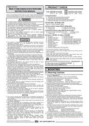
1. OUTLINE<br />
1.1 Product Check<br />
Before using this product, check each of the following.<br />
• Model code<br />
• Check that there are no scratches or breakage in external appearance (case, front panel, terminal, etc).<br />
• Check that all of the accessories delivered are complete. (See below)<br />
Accessories Q’TY Remarks<br />
<strong>COM</strong>-<strong>JC</strong> [For FB100/FB400/FB900] Installation Manual (IMR01Y01-E) 1 Enclosed with <strong>instrument</strong><br />
<strong>COM</strong>-<strong>JC</strong> [For FB100/FB400/FB900] Quick Instruction Manual (IMR01Y11-E) 1 Enclosed with <strong>instrument</strong><br />
<strong>COM</strong>-<strong>JC</strong> [For FB100/FB400/FB900] Communication Data List (IMR01Y16-E) 1 Enclosed with <strong>instrument</strong><br />
<strong>COM</strong>-<strong>JC</strong> [For FB100/FB400/FB900] Instruction Manual (IMR01Y06-E5) 1 This manual (sold separately)<br />
If any of the products are missing, damaged, or if your manual is <strong>inc</strong>omplete, please contact<br />
RKC sales office or the agent.<br />
1.2 Model Code<br />
Check that the product received is correctly specified by referring to the following model code list:<br />
If the product is not identical to the specifications, please contact RKC sales office or the agent.<br />
(1) Corresponding to the RKC controller<br />
01: FB100/400/900<br />
(2) RUN/STOP logic selection<br />
1: 0: RUN<br />
1: STOP<br />
2: 0: STOP<br />
1: RUN<br />
<strong>COM</strong>- <strong>JC</strong> ∗ 01- <br />
(1) (2)<br />
2<br />
IMR01Y06-E5
1. OUTLINE<br />
1.3 Parts Description<br />
Terminal cover<br />
Terminal base<br />
Indication<br />
lamps<br />
Station number<br />
setting switch<br />
Mainframe<br />
Dip switch<br />
[Details of Indication lamps]<br />
CC-Link<br />
connection<br />
terminals<br />
(<strong>COM</strong>.PORT)<br />
Terminal cover<br />
Mounting<br />
bracket<br />
Front view<br />
Left side view<br />
CC-Link communication<br />
speed setting switch<br />
RD<br />
SD<br />
RUN<br />
FAIL<br />
• Indication lamps<br />
FAIL [Red] • When <strong>instrument</strong> abnormally: ON<br />
• CC-Link setting error:<br />
ON<br />
• CC-Link operation error:<br />
Flashes slowly<br />
• CC-Link setting is changed:<br />
Flashes rapidly<br />
RUN [Green] • When normally: ON<br />
• Operation error:<br />
Flashes slowly<br />
• During controller communication initialization: Flashes rapidly<br />
SD [Green] During CC-Link data send: ON<br />
RD [Green] During CC-Link data receive: ON<br />
• CC-Link connection terminals<br />
<strong>COM</strong>. PORT<br />
Terminals for PLC (Master) connection<br />
• Switches<br />
Station number setting switch<br />
CC-Link communication<br />
peed setting switch<br />
Dip switch<br />
• Other<br />
Terminal cover<br />
Mounting bracket<br />
Terminal base<br />
Mainframe<br />
Set the station number for CC-Link<br />
Set the communication speed for CC-Link<br />
• Set the number of Occupied station/Extension cyclic for CC-Link<br />
• Set the communication speed for controller communication<br />
Terminal cover above and below the <strong>COM</strong>-<strong>JC</strong><br />
• Used for the DIN rail mounting<br />
• When panel mounted, two mounting brackets are required for the<br />
upper and lower sides (one required for the upper side: separately<br />
sold).<br />
Part of the terminal and base of <strong>COM</strong>-<strong>JC</strong><br />
(There is the termination resistor transfer switch in the inside of<br />
terminal base)<br />
Part of the mainframe of <strong>COM</strong>-<strong>JC</strong><br />
IMR01Y06-E5 3
2. HANDLING PROCEDURES<br />
Conduct the setting necessary for performing communication in accordance with the following<br />
procedure.<br />
<strong>COM</strong>-<strong>JC</strong> Setting<br />
Mounting<br />
Wiring and<br />
Connection<br />
PLC and Controller<br />
Settings<br />
Set the CC-Link station number, Communication speed and<br />
Occupied station/Extended cyclic of <strong>COM</strong>-<strong>JC</strong> and Controller<br />
communication speed.<br />
See 5. SETTING (P. 16)<br />
Install the <strong>COM</strong>-<strong>JC</strong>.<br />
• See 3. MOUNTING (P. 5)<br />
• For controller, see FB100 Installation Manual<br />
(IMR01W12-E) or FB400/FB900 Installation<br />
Manual (IMR01W01-E)<br />
Connect power supply wires to the <strong>COM</strong>-<strong>JC</strong>, and also connect<br />
the <strong>COM</strong>-<strong>JC</strong> to the controller and the <strong>COM</strong>-<strong>JC</strong> to the PLC,<br />
respectively.<br />
• See 4. WIRING (P. 8)<br />
• For controller, see FB100 Installation Manual<br />
(IMR01W12-E) or FB400/FB900 Installation<br />
Manual (IMR01W01-E)<br />
Set the PLC and controller.<br />
• See 8.3 Use Instruments Setting (P. 82)<br />
• For controller, see FB100 Communication Quick<br />
Manual (IMR01W15-E) or FB400/FB900<br />
Communication Quick Manual (IMR01W07-E)<br />
Device Assignment<br />
Do assignments of Remote input/output and Remote register.<br />
See 8.4 Device Assignments Example (P. 84)<br />
Program Creation<br />
Create the sequence program of PLC.<br />
See 8.5 Sample Program (P. 87)<br />
To avoid error at operation start-up, <strong>COM</strong>-<strong>JC</strong> must be powered on LAST (after the<br />
Controller, PLC, etc.).<br />
4 IMR01Y06-E5
3. MOUNTING<br />
This chapter describes installation environment, mounting cautions, dimensions and mounting<br />
procedures.<br />
!<br />
WARNING<br />
To prevent electric shock or <strong>instrument</strong> failure, always turn off the power before<br />
mounting or removing the <strong>instrument</strong>.<br />
3.1 Mounting Cautions<br />
(1) This <strong>instrument</strong> is intended to be used under the following environmental conditions. (IEC61010-1)<br />
[OVERVOLTAGE CATEGORY II, POLLUTION DEGREE 2]<br />
(2) Use this <strong>instrument</strong> within the following environment conditions:<br />
• Allowable ambient temperature: −10 to +50 °C<br />
• Allowable ambient humidity: 5 to 95 % RH<br />
(Absolute humidity: MAX.W.C 29.3 g/m 3 dry air at 101.3 kPa)<br />
• Installation environment conditions: Indoor use<br />
Altitude up to 2000 m<br />
(3) Avoid the following conditions when selecting the mounting location:<br />
• Rapid changes in ambient temperature which may cause condensation.<br />
• Corrosive or inflammable gases.<br />
• Direct vibration or shock to the mainframe.<br />
• Water, oil, chemicals, vapor or steam splashes.<br />
• Excessive dust, salt or iron particles.<br />
• Excessive induction noise, static electricity, magnetic fields or noise.<br />
• Direct air flow from an air conditioner.<br />
• Exposure to direct sunlight.<br />
• Excessive heat accumulation.<br />
(4) Mount this <strong>instrument</strong> in the panel considering the following conditions:<br />
• Ensure at least 50 mm space on top and bottom of the <strong>instrument</strong> for maintenance and<br />
environmental reasons.<br />
• Do not mount this <strong>instrument</strong> directly above equipment that generates large amount of heat<br />
(heaters, transformers, semi-conductor functional devices, large-wattage resistors).<br />
• If the ambient temperature rises above 50 °C, cool this <strong>instrument</strong> with a forced air fan, etc.<br />
Cooled air should not blow directly on this <strong>instrument</strong>.<br />
• In order to improve safety and the immunity to withstand noise, mount this <strong>instrument</strong> as far<br />
away as possible from high voltage equipment, power lines, and rotating machinery.<br />
High voltage equipment: Do not mount within the same panel.<br />
Power lines:<br />
Separate at least 200 mm.<br />
Rotating machinery: Separate as far as possible.<br />
(5) If this <strong>instrument</strong> is permanently connected to equipment, it is important to <strong>inc</strong>lude a switch or<br />
circuit-breaker into the installation. This should be in close proximity to the equipment and within<br />
easy reach of the operator. It should be marked as the disconnecting device for the equipment.<br />
IMR01Y06-E5 5
3. MOUNTING<br />
3.2 Dimensions<br />
109.5 9.5 3 30<br />
(Unit: mm)<br />
5<br />
125<br />
78<br />
3.3 DIN Rail Mounting<br />
• Mounting procedures<br />
1. Pull down the mounting bracket at the bottom of the <strong>instrument</strong> (A). Attach the hooks on the top<br />
of the <strong>instrument</strong> to the DIN rail and push the lower section into place on the DIN rail (B).<br />
2. Slide the mounting bracket up to secure the <strong>instrument</strong> to the DIN rail (C).<br />
DIN rail<br />
(B) Push<br />
Mounting<br />
bracket<br />
(A) Pull down<br />
(C) Locked<br />
6<br />
IMR01Y06-E5
3. MOUNTING<br />
• Removal procedures<br />
1. Turn the power OFF.<br />
2. Remove the wiring.<br />
3. Pull down a mounting bracket with<br />
a blade screwdriver (A). Lift the<br />
<strong>instrument</strong> from bottom, and take it<br />
off (B).<br />
(B) Lift and take<br />
off<br />
(A) Pull down<br />
3.4 Panel Mounting<br />
• Mounting procedures<br />
1. Pull down the mounting bracket (A) until locked and that a mounting hole appears.<br />
2. Prepare one mounting bracket per <strong>instrument</strong> (B) sold separately (KSRX-55) and then insert it in<br />
the rear of the terminal board at top of the <strong>instrument</strong> until locked but a mounting hole does not<br />
disappear.<br />
3. Mount each module directly on the panel with screws which are inserted in the mounting holes of<br />
the top and bottom mounting brackets.<br />
Recommended tightening torque: 0.3 N⋅m (3 kgf⋅cm)<br />
The customer needs to provide the M3 size screws. Select the screw length that matches the<br />
mounting panel.<br />
(B) Insert<br />
Mounting dimensions<br />
(Unit: mm)<br />
Mounting<br />
holes<br />
Mounting bracket<br />
(Sold separately)<br />
(KSRX-55)<br />
(A) Pull down<br />
M3<br />
130.5 ± 0.2<br />
IMR01Y06-E5 7
4. WIRING<br />
This chapter describes wiring cautions, terminal configuration and connections.<br />
4.1 Wiring Cautions<br />
!<br />
WARNING<br />
• To prevent electric shock or <strong>instrument</strong> failure, do not turn on the power until<br />
all wiring is completed. Make sure that the wiring is correct before applying<br />
power to the <strong>instrument</strong>.<br />
• To prevent electric shock or <strong>instrument</strong> failure, turn off the power before<br />
connecting or disconnecting the <strong>instrument</strong> and peripheral equipment.<br />
• To avoid noise induction, keep communication signal wire away from <strong>instrument</strong> power line, load<br />
lines and power lines of other electric equipment.<br />
• If there is electrical noise in the vicinity of the <strong>instrument</strong> that could affect operation, use a noise filter.<br />
− Shorten the distance between the twisted power supply wire pitches to achieve the most effective<br />
noise reduction.<br />
− Always install the noise filter on a grounded panel. Minimize the wiring distance between the<br />
noise filter output and the <strong>instrument</strong> power supply terminals to achieve the most effective noise<br />
reduction.<br />
− Do not connect fuses or switches to the noise filter output wiring as this will reduce the<br />
effectiveness of the noise filter.<br />
• Power supply wiring must be twisted and have a low voltage drop.<br />
• For an <strong>instrument</strong> with 24 V power supply, supply power from a SELV circuit.<br />
• A suitable power supply should be considered in end-use equipment. The power supply must be in<br />
compliance with a limited-energy circuits (maximum available current of 8 A).<br />
• Use the solderless terminal appropriate to the screw size (M3).<br />
5.9 mm or less<br />
3.2 mm or more<br />
Recommended tightening torque:<br />
0.4 N⋅m (4 kgf⋅cm)<br />
• Make sure that the any wiring such as solderless terminal is not in contact with the adjoining<br />
terminals.<br />
8 IMR01Y06-E5
4. WIRING<br />
4.2 Terminal Configuration<br />
The terminal layout is as follows.<br />
Upper-side<br />
terminal<br />
Controller<br />
communication<br />
RS-485<br />
3<br />
2 1<br />
7 6 5 4<br />
T/R(B)<br />
5<br />
T/R(A)<br />
1<br />
SG<br />
4<br />
: The part of internal wiring<br />
Power supply 11 10 9 8<br />
Ground<br />
14 13 12<br />
9 8<br />
12<br />
+<br />
DC<br />
−<br />
24 V<br />
Lower-side<br />
terminal<br />
FG<br />
As controller communication terminal Nos. 1, 4 and 5 are internally connected to terminal Nos. 3,<br />
6 and 7, any terminals can be used.<br />
As ground and power supply terminal Nos. 8, 9 and 12 are internally connected to terminal Nos.<br />
10, 11 and 14, any terminals can be used.<br />
Terminal No. 2 and No. 13 is not used.<br />
IMR01Y06-E5 9
4. WIRING<br />
4.3 Connection to PLC<br />
• Connection method<br />
The PLC (Master station) and <strong>COM</strong>-<strong>JC</strong> make multi-drop connection in CC-Link dedicated cable Ver. 1.10.<br />
PLC<br />
Master station<br />
<strong>COM</strong>-<strong>JC</strong><br />
Termination<br />
resistor<br />
Termination<br />
resistor<br />
CC-Link dedicated cable<br />
Ver. 1.10<br />
Station to station<br />
cable length:<br />
20 cm or more<br />
Up to 61 stations<br />
Up to 64 stations:<br />
1 station occupied 1 time<br />
• Communication speed and maximum transmitter distance<br />
(Use the CC-Link dedicated cable Ver. 1.10)<br />
Communication<br />
speed<br />
Station to station<br />
cable length<br />
Maximum transmitter distance<br />
(maximum length of network)<br />
10 Mbps 100 m<br />
5 Mbps 160 m<br />
2.5 Mbps 20 cm or more<br />
400 m<br />
625 kbps 900 m<br />
156 kbps<br />
1200 m<br />
10<br />
IMR01Y06-E5
4. WIRING<br />
• Terminal numbers and signal details<br />
CC-Link connection terminals<br />
1: DA<br />
2: DB<br />
3: DG<br />
4: SLD<br />
5: FG<br />
Terminal screws<br />
Screws size: M3<br />
Recommended tightening torque: 0.4 N⋅m (4 kgf⋅cm)<br />
Terminal No. Signal name Symbol Cable color<br />
1 Data A DA Blue<br />
2 Data B DB White<br />
3 Data ground DG Yellow<br />
4 Shield SLD Grounding wire (Shield)<br />
5 Frame ground FG ⎯<br />
The CC-Link connecting terminal cannot do on-line installation or dismount for terminal<br />
block of dismount impossibility. The device cannot be replaced unless the link is set offline.<br />
In addition, FG (flame ground) terminal of terminal number 5 is FG in a CC-Link function,<br />
and it is not FG of <strong>instrument</strong> all.<br />
Ground both ends of the shield wire on the twisted pair cable via the SLD or FG<br />
terminal of each module. In addition, the SLD terminal is internally connected with the<br />
FG terminal.<br />
Do not ground the <strong>instrument</strong> together with other equipment.<br />
In addition, use grounding wires with across section of 2.0 mm 2 or more. (Ground<br />
resistance: 100 ohm or less)<br />
For cable specifications, connection method and vendor, see the website of CC-Link Partner<br />
Association.<br />
URL: http://www.cc-link.org/<br />
IMR01Y06-E5 11
4. WIRING<br />
• Connection diagram<br />
Always connect a termination resistor between the DA and DB terminals of the module to<br />
be located at the far end.<br />
Termination resistor: 110 Ω ± 5 % 1/2 W<br />
Master station<br />
<strong>COM</strong>-<strong>JC</strong><br />
<strong>COM</strong>-<strong>JC</strong><br />
TR<br />
DA<br />
DB<br />
DG<br />
SLD<br />
FG<br />
CC-Link dedicated<br />
cable Ver. 1.10<br />
DA<br />
DB<br />
DG<br />
SLD<br />
FG<br />
CC-Link dedicated<br />
cable Ver. 1.10<br />
DA<br />
DB<br />
DG<br />
SLD<br />
FG<br />
TR<br />
TR: Termination resistor<br />
The CC-Link dedicated cable Ver. 1.10 is provided by the customer.<br />
12<br />
IMR01Y06-E5
4. WIRING<br />
4.4 Connection to Controller<br />
Conduct wiring between the <strong>COM</strong>-<strong>JC</strong> and controller (FB100/400/900) as shown in the following.<br />
When conducting wiring to the FB100/400/900, always conduct wiring to the<br />
Communication 1 terminal.<br />
• Communication terminal number and signal details<br />
Terminal No.<br />
FB100 FB400/900<br />
Signal name Symbol<br />
13 25 Signal ground SG<br />
14 26 Send/receive data T/R (A)<br />
15 27 Send/receive data T/R (B)<br />
• Wiring [FB400/900] (Connections are similar for the FB100)<br />
<strong>COM</strong>-<strong>JC</strong><br />
RS-485<br />
Paired wire<br />
FB400/900<br />
(−)<br />
SG<br />
T/R (A)<br />
4<br />
1<br />
25<br />
26<br />
SG<br />
T/R (A)<br />
(−)<br />
(+)<br />
*R<br />
T/R (B)<br />
5<br />
27<br />
T/R (B)<br />
(+)<br />
Terminal block<br />
Shielded twisted<br />
pair wire<br />
Communication terminals<br />
(communication 1 side)<br />
•<br />
•<br />
•<br />
FB400/900<br />
25<br />
26<br />
SG<br />
T/R (A)<br />
(−)<br />
*R: Termination resistors (Example: 120 Ω 1/2 W)<br />
*R<br />
27<br />
T/R (B)<br />
(+)<br />
Maximum controller connections: 31 controllers<br />
Communication terminals<br />
(communication 1 side)<br />
The cable is provided by the customer.<br />
The termination resistor existing within the <strong>COM</strong>-<strong>JC</strong> can be connected or disconnected by<br />
the switch. (Factory set value: Termination resistor connected)<br />
[See 4.5 Installation of Termination Resistor (P. 14)]<br />
IMR01Y06-E5 13
4. WIRING<br />
4.5 Installation of Termination Resistor<br />
Procedure for setting a termination resistor to Controller communication (RS-485) and its setting<br />
position are described in the following.<br />
• Termination resistor setting position<br />
If the <strong>COM</strong>-<strong>JC</strong> is connected to the extreme end of the communication line, install one termination<br />
resistor each to the <strong>COM</strong>-<strong>JC</strong> and the controller located most distantly from the <strong>COM</strong>-<strong>JC</strong>.<br />
Controller communication (RS-485: Modbus)<br />
Termination<br />
resistor ON<br />
(Factory<br />
set value)<br />
<strong>COM</strong>-<strong>JC</strong><br />
FB100<br />
FB400<br />
FB900<br />
1<br />
FB100<br />
FB400<br />
FB900<br />
2<br />
FB100<br />
FB400<br />
FB900<br />
31<br />
Connect a termination<br />
resistor to the terminals<br />
from exterior.<br />
For installation position of<br />
the termination resistor, see<br />
• Wiring (P. 13).<br />
• Setting procedure of termination resistor (<strong>COM</strong>-<strong>JC</strong>)<br />
As the <strong>COM</strong>-<strong>JC</strong> is internally provided with a selector switch for choosing the ON/OFF of a<br />
termination resistor, it is not required to externally install the termination resistor.<br />
(Factory set value: Termination resistor connected)<br />
1. Turn off the power supply of the <strong>COM</strong>-<strong>JC</strong>.<br />
Do not separate the mainframe from terminal base with the power turned on. If so,<br />
<strong>instrument</strong> failure may result.<br />
2. Pull out the mainframe itself toward you while pushing the locks at its top and bottom (1), and<br />
then separate it from the terminal base (2).<br />
Upper-side<br />
lock<br />
Terminal base<br />
(1) Push<br />
Mainframe<br />
(2) Pull out<br />
Top view<br />
Lower-side<br />
lock<br />
Bottom view<br />
(1) Push<br />
Removing the module mainframe<br />
14<br />
IMR01Y06-E5
4. WIRING<br />
3. Turn on the termination resistor transfer switch in the terminal base.<br />
The <strong>COM</strong>-<strong>JC</strong> is shipped from the factory with the selector switch set to “ON: Termination<br />
resistor connected.”<br />
Termination resistor<br />
transfer switch<br />
OFF<br />
ON<br />
Termination<br />
resistor OFF<br />
Termination<br />
resistor ON<br />
(120 Ω 1/2 W)<br />
Factory set value: ON<br />
A terminal base of the state which removed module mainframe<br />
4. Push the mainframe thus separated in the terminal base until firmly locked.<br />
Terminal base<br />
Mainframe<br />
Push the module<br />
mainframe until<br />
firmly locked<br />
Mounting the module mainframe<br />
IMR01Y06-E5 15
5. SETTING<br />
!<br />
WARNING<br />
• To prevent electric shock or <strong>instrument</strong> failure, always turn off the power<br />
before setting the switch.<br />
• To prevent electric shock or <strong>instrument</strong> failure, never touch any section other<br />
than those instructed in this manual.<br />
CAUTION<br />
Do not separate the mainframe from the terminal base with the power turned on.<br />
If so, <strong>instrument</strong> failure may result.<br />
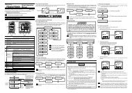
5.1 Station Number Setting<br />
Set the station number of CC-Link. For this setting, use a small blade screwdriver.<br />
When set to any value out of the setting range, the <strong>COM</strong>-<strong>JC</strong> becomes the FAIL state.<br />
High-order digit<br />
setting<br />
(Set value × 10)<br />
Low-order digit<br />
setting<br />
(Set value × 1)<br />
Station number<br />
setting switch<br />
Setting range:<br />
1 to 61 (4 stations occupied 1 time/<br />
4 stations occupied 2 times)<br />
1 to 64 (1 station occupied 1 time)<br />
Factory set value: 0<br />
16 IMR01Y06-E5
5. SETTING<br />
5.2 Communication Speed Setting<br />
The rotary switch at the left side of the mainframe sets the communication speed of the CC-Link.<br />
For this setting, use a small blade screwdriver.<br />
When set to any value out of the setting range, the <strong>COM</strong>-<strong>JC</strong> becomes the FAIL state.<br />
Communication speed<br />
setting switch<br />
Left side view<br />
Setting range: 0 to 4<br />
Factory set value: 0 (156 kbps)<br />
• Communication speed and maximum transmitter distance<br />
(Use the CC-Link dedicated cable Ver. 1.10)<br />
Communication<br />
speed setting<br />
Communication<br />
speed<br />
Maximum transmitter distance<br />
(maximum length of network)<br />
0 156 kbps 1200 m<br />
1 625 kbps 900 m<br />
2 2.5 Mbps 400 m<br />
3 5 Mbps 160 m<br />
4 10 Mbps 100 m<br />
IMR01Y06-E5 17
5. SETTING<br />
5.3 Occupied Station/Extended Cyclic and Controller<br />
Communication Speed Setting<br />
The Dip switch at the left side of the mainframe sets the occupied station/extended cyclic and<br />
controller communication speed.<br />
Dip switch<br />
ON<br />
ON<br />
1 2 3 4 5 6 7 8<br />
OFF<br />
Left side view<br />
1 2 Controller communication speed<br />
OFF OFF 38400 bps<br />
ON OFF 9600 bps<br />
OFF ON 19200 bps<br />
ON ON 38400 bps<br />
Factory set value: 19200 bps<br />
3 4 5 Number of Occupied stations/Extended cyclic<br />
OFF OFF OFF 4 stations occupied 1 time (8 controllers assignment)<br />
ON OFF OFF 4 stations occupied 1 time (16 controllers assignment)<br />
OFF ON OFF 4 stations occupied 2 times (16 controllers assignment)<br />
ON ON OFF 4 stations occupied 2 times (31 controllers assignment)<br />
OFF OFF ON 1 station occupied 1 time (1 controller assignment)<br />
ON OFF ON 1 station occupied 1 time (2 controllers assignment)<br />
OFF ON ON<br />
ON ON ON<br />
Don't set this one<br />
Factory set value: 4 stations occupied 1 time (8 controllers assignment)<br />
CC-Link version varies according to the specification of Occupied station/Extended<br />
cyclic of the <strong>COM</strong>-<strong>JC</strong>. Select CC-Link version of PLC by setting the following<br />
CC-Link specifications:<br />
• 1 station occupied 1 time/4 stations occupied 1 time: CC-Link Ver. 1.10<br />
• 4 stations occupied 2 times: CC-Link Ver. 2.00<br />
6 7 8<br />
OFF OFF OFF Fixed<br />
18<br />
IMR01Y06-E5
6. CC-Link <strong>COM</strong>MUNICATION<br />
6.1 Communication Between Master Station and <strong>COM</strong>-<strong>JC</strong><br />
(Remote Device Station)<br />
The <strong>COM</strong>-<strong>JC</strong> which is a remote device station can process Remote input (RX), Remote output (RY)<br />
and Remote registers (RWw and RWr).<br />
• Outline of communication between master station and <strong>COM</strong>-<strong>JC</strong> (Remote device station)<br />
CPU of PLC<br />
Master station<br />
<strong>COM</strong>- <strong>JC</strong><br />
(Remote device station)<br />
Network<br />
parameters<br />
(1)<br />
Network<br />
parameters<br />
Automatic refresh<br />
parameters<br />
X<br />
Y<br />
W<br />
W<br />
(3)<br />
Automatic refresh<br />
Automatic refresh<br />
Automatic refresh<br />
Automatic refresh<br />
Buffer memory<br />
Remote input<br />
(RX)<br />
Remote<br />
register (RWw)<br />
(2)<br />
Link scan<br />
(4) (5)<br />
Link scan<br />
(6) (7)<br />
(9)<br />
Remote output<br />
(RY)<br />
Remote<br />
register (RWr)<br />
Link scan<br />
(8)<br />
Link scan<br />
Remote input<br />
(RX)<br />
Remote output<br />
(RY)<br />
Remote<br />
register (RWw)<br />
Remote<br />
register (RWr)<br />
[Event state, etc. ]<br />
[RUN/STOP<br />
transfer, extension<br />
No. setting, etc.]<br />
[Set value (SV)]<br />
[Measured value<br />
(PV)]<br />
(1) When the PLC system is powered on, the network parameters in the<br />
PLC CPU are transferred to the master station, and the CC-Link<br />
system automatically starts up.<br />
[Data link startup]<br />
(2) The Remote input RX of a <strong>COM</strong>-<strong>JC</strong> (Remote device station) is<br />
stored automatically (for each link scan) in the master station’s<br />
Remote input RX buffer memory.<br />
(3) The input status stored in the Remote input RX buffer memory is<br />
stored in the CPU device set with the automatic refresh parameters.<br />
[Remote input]<br />
(4) The ON/OFF data of the CPU device set with the automatic refresh<br />
parameters is stored in the Remote output RY buffer memory.<br />
(5) Remote output RY is automatically set to ON/OFF (for each link<br />
scan) according to the output status stored in the Remote output RY<br />
buffer memory.<br />
[Remote output]<br />
IMR01Y06-E5 19
6. CC-Link <strong>COM</strong>MUNICATION<br />
(6) The transmission data of the CPU device set with the automatic<br />
refresh parameters is stored in the Remote register RWw buffer<br />
memory.<br />
(7) The data stored in the Remote register RWw buffer memory is<br />
automatically sent to the Remote register RWw of <strong>COM</strong>-<strong>JC</strong> (Remote<br />
device station).<br />
(8) The Remote register RWr data of a <strong>COM</strong>-<strong>JC</strong> (Remote device<br />
station) is automatically stored in the Remote register RWr buffer<br />
memory of the master station.<br />
(9) The Remote register RWr data of a <strong>COM</strong>-<strong>JC</strong> (Remote device station)<br />
stored in the Remote register RWr buffer memory is stored in the<br />
CPU device set with the automatic refresh parameters.<br />
[Writing to the Remote<br />
register RWw]<br />
[Reading from the Remote<br />
register (RWr)]<br />
With the master station (PLC) set to the STOP state, neither the Remote output (RY) nor<br />
data write to the Remote register (RWw) is reflected to the <strong>COM</strong>-<strong>JC</strong>.<br />
For details of the communication, see the Instruction manual for PLC.<br />
20<br />
IMR01Y06-E5
6. CC-Link <strong>COM</strong>MUNICATION<br />
6.2 CC-Link Flag Operation<br />
Remote input/output and Remote register flag operations are as follows.<br />
[Example] When the Occupied station/Extended cyclic of <strong>COM</strong>-<strong>JC</strong> is set to 1 station occupied 1 time.<br />
• Initialize request processing at power on<br />
• Initialize processing request from Remote device station (<strong>COM</strong>-<strong>JC</strong>)<br />
If the <strong>COM</strong>-<strong>JC</strong> is initialized at power on, the Initialize data processing request flag [RX(n+1)8] is<br />
turned on. Thus, turn on the Initialize data processing completion flag [RY(n+1)8].<br />
When <strong>COM</strong>-<strong>JC</strong> becomes a ready state, a Remote ready [RX(n+1)B] is turned on.<br />
Initialize data processing<br />
request flag [RX(n+1)8]<br />
Initialize data processing<br />
completion flag [RY(n+1)8]]<br />
Remote ready [RX(n+1)B]<br />
ON<br />
OFF<br />
ON<br />
OFF<br />
ON<br />
OFF<br />
• Initialize processing request from Master station (PLC)<br />
This is an <strong>COM</strong>-<strong>JC</strong> initialize setting request. As there is no initialize data specifically, no processing is<br />
required.<br />
Initialize data setting<br />
request flag [RY(n+1)9]<br />
Initialize data setting<br />
completion flag [RX(n+1)9]<br />
Remote ready [RX(n+1)B]<br />
ON<br />
OFF<br />
ON<br />
OFF<br />
ON<br />
OFF<br />
IMR01Y06-E5 21
6. CC-Link <strong>COM</strong>MUNICATION<br />
• Error flag/Error reset processing<br />
When the Error status flag [RX(n+1)A] is turned on, the error code is stored in the remote register.<br />
If the Error reset request flag [RY(n+1)A] is turned on when an error occurs, [RX(n+1)A] is turned off<br />
to clear the error code.<br />
Error status flag<br />
[RX(n+1)A]<br />
Error reset<br />
request flag<br />
[RY(n+1)A]<br />
Remote ready<br />
[RX(n+1)B]<br />
ON<br />
OFF<br />
ON<br />
OFF<br />
ON<br />
OFF<br />
• Extension number for display selection processing<br />
The content of the extended display remote register is selected.<br />
After the Extension number for display [RYn0 to RYn5] is set, turn on the Extended display flag<br />
[RYnC]. After the data in the Remote register [RWrn to RWrn+3] is displayed, check that Extended<br />
display completion [RXnC] is turned on and then turn off the Extended display flag [RYnC]. If the<br />
extended display flag is turned off, the extended display completion is turned off.<br />
Extension number<br />
for display<br />
[RYn0 to RYn5]<br />
Extended display flag<br />
[RYnC]<br />
Extended display<br />
completion<br />
[RXnC]<br />
Remote register<br />
[RWrn to RWrn+3]<br />
ON<br />
OFF<br />
ON<br />
OFF<br />
ON<br />
OFF<br />
ON<br />
OFF<br />
Extension number 0 Extension number 1<br />
Extension number 0 Extension number 1<br />
(R/O data: Automatically updated)<br />
22<br />
IMR01Y06-E5
6. CC-Link <strong>COM</strong>MUNICATION<br />
• Extension number for setting selection processing<br />
The content of the extended setting remote register is selected and the set value is changed.<br />
After the Extension number for setting [RYn6 to RYnB] is set, turn on the Extended setting flag<br />
(Setting update flag) [RYnD]. After the content of the Remote register [RWwm to RWwm+3] is set,<br />
check that Extended setting completion [RXnD] is turned on and then turn off the Extended setting<br />
flag (Setting update flag) [RYnD]. If the Extended setting flag (Setting update flag) [RYnD] is turned<br />
off, the Extended setting completion [RXnD] is turned off.<br />
Extension number<br />
for setting<br />
[RYn6 to RYnB]<br />
Extended setting flag<br />
(Setting update flag)<br />
[RYnD]<br />
Extended setting<br />
completion<br />
[RXnD]<br />
Remote register<br />
[RWwm to RWwm+3]<br />
ON<br />
OFF<br />
ON<br />
OFF<br />
ON<br />
OFF<br />
ON<br />
OFF<br />
Data usage<br />
Data usage<br />
Regardless of the number of Occupied stations and the Extended cyclic, the above<br />
processing is also necessary if the Set value (SV) assigned to the Remote register (RWw) as<br />
a fixed value is changed.<br />
• AT start procedure<br />
Instructs AT execution.<br />
Remote register [RWwn]<br />
(Extension number 4:<br />
PID/AT transfer)<br />
Data = 1<br />
Data = 0<br />
Extended setting flag<br />
(Setting update flag)<br />
[RYnD]<br />
Extended setting<br />
completion<br />
[RXnD]<br />
AT setting status<br />
PID/AT transfer status<br />
[RXn4]<br />
ON<br />
OFF<br />
ON<br />
OFF<br />
ON<br />
OFF<br />
ON<br />
OFF<br />
IMR01Y06-E5 23
6. CC-Link <strong>COM</strong>MUNICATION<br />
6.3 Processing of Numeric Data Values<br />
Numeric data values used via communication with the PLC and processed by <strong>COM</strong>-<strong>JC</strong> <strong>inc</strong>lude those<br />
with and without decimal points and also those with minus signs.<br />
• For numeric data value without decimal point<br />
If there is no decimal point, the value is processed as it is.<br />
In parameters which only have ON or OFF status, 1 = ON, 0 = OFF.<br />
[Example]<br />
A signal wire for temperature input is disconnected and the burnout state occurs.<br />
→ Read value corresponding to extension number 63 (comprehensive event state):<br />
1 (Hexadecimal number: 0001H)<br />
• For numeric data value with decimal point<br />
The decimal point is omitted.<br />
[Example]<br />
When the Measured value (PV) of controller (device address 1) is 120.5 °C<br />
→ Read value of Remote register (RWrn) [Measured value (PV) of device address 1]:<br />
1205 (Hexadecimal number: 04B5H)<br />
→ Read value corresponding to extension number 0 [Measured value (PV)]:<br />
1205 (Hexadecimal number: 04B5H)<br />
• For numeric data value with minus sign<br />
The value is expressed as a 2’s complement value which is obtained by subtracting the minus value<br />
from the hexadecimal number 10000H.<br />
[Example]<br />
When the Measured value (PV) of controller (device address 1) is −2.5 °C<br />
→ Read value of Remote register (RWrn) [Measured value (PV) of device address 1]:<br />
Hexadecimal number: FFE7H (10000H − 25 = 10000H − 19H = FFE7H)<br />
→ Read value corresponding to extension number 0 [Measured value (PV)]:<br />
Hexadecimal number: FFE7H (10000H − 25 = 10000H − 19H = FFE7H)<br />
Read data of unused item becomes default value.<br />
Any attempt to write to an unused item is not processed as an error. Data cannot be written<br />
into an unused item.<br />
24<br />
IMR01Y06-E5
7. <strong>COM</strong>MUNICATION DATA LIST<br />
7.1 Remote Input/Output<br />
Remote input (RX) and Remote output (RY) is ON/OFF data.<br />
“n” in the table is the address assigned to the master station by the station number setting.<br />
It can be calculated by the following equation. However, the computing equation is when a network is<br />
configured only by using our <strong>COM</strong>-<strong>JC</strong>s and the number of all Occupied stations/Extended cyclic are<br />
at the same setting.<br />
Number of Occupied stations/<br />
Extended cyclic setting<br />
Equation<br />
1 station occupied 1 time n = (Station number* − 1) × 2<br />
4 stations occupied 1 time n = (Station number* − 1) × 2<br />
4 stations occupied 2 times n = (Station number* − 1) × 3.5<br />
* Station number when there is one occupied station: 1 to 64 (each number can be set)<br />
Station number when there are four occupied stations: 1 to 61<br />
(Four stations are occupied for each station<br />
number, and thus only numbers that are<br />
<strong>inc</strong>rements of four can be set: 1, 5, 9 …61)<br />
As the calculation result is expressed in decimal number it is converted to hexadecimal number<br />
before substituted for “n” in the table.<br />
Example: When the <strong>COM</strong>-<strong>JC</strong> is set to 4 stations occupied 1 time and its station number is 5.<br />
n = (5 − 1) × 2 = 8 (Decimal number) → 8 (Hexadecimal number)<br />
For station number 5: Remote inputs RXn0 to RX (n+7) F → RX80 to RXFF<br />
Remote outputs RYn0 to RY (n+7) F → RY80 to RYFF<br />
If the network consists of <strong>COM</strong>-<strong>JC</strong> modules with differing Number of Occupied stations/<br />
Extended cyclic settings, use for “n” the total of the highest digits of the number of assigned<br />
registers with station number lower than the module’s own station in order from the lowest<br />
station number.<br />
Number of Occupied stations/<br />
Extended cyclic setting<br />
Number of assigned registers<br />
1 station occupied 1 time 20H (Hexadecimal number)<br />
4 stations occupied 1 time 80H (Hexadecimal number)<br />
4 stations occupied 2 times E0H (Hexadecimal number)<br />
Example: Calculation of “n” when the network consists of three <strong>COM</strong>-<strong>JC</strong> modules and the<br />
station numbers and Number of Occupied stations/Extended cyclic settings are as<br />
shown below.<br />
1st module [Station number 1]: 4 stations occupied 2 times<br />
n = 0 (No station numbers less than the module’s own station, thus 0)<br />
Remote inputs: RXn0 to RX (n+D) F → RX00 to RXDF<br />
Remote outputs: RYn0 to RY (n+D) F → RY00 to RYDF<br />
2nd module [Station number 5]: 1 station occupied 1 time<br />
n = E (Highest digit of E0H, the number of assigned registers of station 1)<br />
Remote inputs: RXn0 to RX (n+1) F → RXE0 to RXFF<br />
Remote outputs: RYn0 to RY (n+1) F → RYE0 to RYFF<br />
3rd module [Station number 6]: 4 stations occupied 1 time<br />
n = E + 2 = 10<br />
(Total of highest digits of E0H and 20H, the number of assigned<br />
registers of station 1 and station 5)<br />
Remote inputs: RXn0 to RX (n+7) F → RX100 to RX17F<br />
Remote outputs: RYn0 to RY (n+7) F → RY100 to RY17F<br />
“Device address from 1 to 31” in the table correspond to controller device address.<br />
IMR01Y06-E5 25
7. <strong>COM</strong>MUNICATION DATA LIST<br />
7.1.1 1 station occupied 1 time<br />
• Remote input<br />
Data direction: <strong>COM</strong>-<strong>JC</strong> (Remote device station) → Master station (PLC)<br />
Data capacity: 32-bit<br />
Address Communication item Data range<br />
Factory<br />
set value<br />
RXn0 Device address 1 Event 1 state 0: OFF<br />
1: ON<br />
⎯<br />
RXn1 Event 2 state ⎯<br />
RXn2 Burnout state 0: OFF<br />
1: ON<br />
⎯<br />
RXn3<br />
Heater break alarm<br />
(HBA) state<br />
0: OFF<br />
1: ON<br />
⎯<br />
RXn4<br />
PID/AT transfer 0: PID control<br />
⎯<br />
1: Autotuning (AT)<br />
RXn5 Device address 2 Event 1 state 0: OFF<br />
⎯<br />
1: ON<br />
RXn6 Event 2 state ⎯<br />
RXn7 Burnout state 0: OFF<br />
1: ON<br />
⎯<br />
RXn8<br />
Heater break alarm 0: OFF<br />
⎯<br />
(HBA) state<br />
1: ON<br />
RXn9<br />
PID/AT transfer 0: PID control<br />
⎯<br />
1: Autotuning (AT)<br />
RXnA Unused ⎯ ⎯<br />
RXnB<br />
RXnC Extended display completion 0: OFF<br />
1: ON<br />
⎯<br />
RXnD Extended setting completion 0: OFF<br />
1: ON<br />
⎯<br />
RXnE Unused ⎯ ⎯<br />
RXnF Hardware error flag 0: OFF<br />
⎯<br />
1: ON<br />
When hardware error of <strong>COM</strong>-<strong>JC</strong><br />
occurred, turned on.<br />
RX(n+1)0 Reserved<br />
⎯ ⎯<br />
•<br />
•<br />
RX(n+1)7<br />
RX(n+1)8 Initialize data processing request flag 0: OFF<br />
1: ON<br />
RX(n+1)9 Initialize data setting completion flag 0: OFF<br />
1: ON<br />
RX(n+1)A Error status flag 0: OFF<br />
1: ON<br />
When self-diagnostics error except<br />
watchdog timer abnormality<br />
occurred in <strong>COM</strong>-<strong>JC</strong>, turned on.<br />
RX(n+1)B Remote ready 0: Not ready state<br />
1: Ready state<br />
⎯<br />
RX(n+1)C Reserved<br />
⎯ ⎯<br />
•<br />
RX(n+1)F<br />
⎯<br />
⎯<br />
⎯<br />
26<br />
IMR01Y06-E5
7. <strong>COM</strong>MUNICATION DATA LIST<br />
• Remote output<br />
Data direction: Master station (PLC) → <strong>COM</strong>-<strong>JC</strong> (Remote device station)<br />
Data capacity: 32-bit<br />
Address Communication item Data range<br />
RYn0 Bit 0<br />
RYn1 Bit 1<br />
RYn2 Bit 2<br />
RYn3 Bit 3<br />
RYn4 Bit 4<br />
RYn5 Bit 5<br />
RYn6 Bit 0<br />
RYn7 Bit 1<br />
RYn8 Bit 2<br />
RYn9 Bit 3<br />
RYnA Bit 4<br />
RYnB Bit 5<br />
Extension number for display<br />
Extension number for setting<br />
Display extension number are specified<br />
by the ON/OFF states of RYn0 to<br />
RYn5.<br />
Data 0: OFF 1: ON<br />
[Decimal number: 0 to 63]<br />
Setting extension number are specified<br />
by the ON/OFF states of RYn6 to<br />
RYnB.<br />
Data 0: OFF 1: ON<br />
[Decimal number: 0 to 63]<br />
Factory<br />
set value<br />
0<br />
RYnC Extended display flag 0: OFF<br />
1: ON<br />
0<br />
RYnD Extended setting flag<br />
0: OFF<br />
0<br />
(Setting update flag)<br />
1: ON<br />
RYnE Unused ⎯ ⎯<br />
RYnF RUN/STOP transfer Logic of RUN/STOP transfer is<br />
0<br />
different by model code.<br />
For <strong>COM</strong>-<strong>JC</strong>∗01-1<br />
0: RUN (Control start)<br />
1: STOP (Control stop)<br />
For <strong>COM</strong>-<strong>JC</strong>∗01-2<br />
0: STOP (Control stop)<br />
1: RUN (Control start)<br />
RY(n+1)0 Reserved ⎯ ⎯<br />
•<br />
RY(n+1)7<br />
RY(n+1)8 Initialize data processing completion 0: OFF<br />
0<br />
flag<br />
1: ON<br />
RY(n+1)9 Initialize data setting request flag 0: OFF<br />
0<br />
1: ON<br />
RY(n+1)A Error reset request flag 0: OFF<br />
1: ON<br />
0<br />
RY(n+1)B Reserved ⎯ ⎯<br />
•<br />
RY(n+1)F<br />
0<br />
IMR01Y06-E5 27
7. <strong>COM</strong>MUNICATION DATA LIST<br />
7.1.2 4 stations occupied 1 time<br />
• Remote input<br />
Data direction: <strong>COM</strong>-<strong>JC</strong> (Remote device station) → Master station (PLC)<br />
Data capacity: 128-bit<br />
Address Communication item Data range<br />
Factory<br />
set value<br />
RXn0 Device address 1 Event 1 state 0: OFF<br />
⎯<br />
1: ON<br />
RXn1 Event 2 state ⎯<br />
RXn2 Burnout state 0: OFF<br />
1: ON<br />
⎯<br />
RXn3<br />
Heater break alarm<br />
(HBA) state<br />
0: OFF<br />
1: ON<br />
⎯<br />
RXn4<br />
PID/AT transfer 0: PID control<br />
1: Autotuning (AT)<br />
⎯<br />
RXn5 Device address 2 Event 1 state 0: OFF<br />
1: ON<br />
⎯<br />
RXn6 Event 2 state ⎯<br />
RXn7 Burnout state 0: OFF<br />
1: ON<br />
⎯<br />
RXn8<br />
Heater break alarm 0: OFF<br />
⎯<br />
(HBA) state<br />
1: ON<br />
RXn9<br />
PID/AT transfer 0: PID control<br />
⎯<br />
1: Autotuning (AT)<br />
RXnA Unused ⎯ ⎯<br />
RXnB<br />
RXnC Extended display completion 0: OFF<br />
1: ON<br />
⎯<br />
RXnD Extended setting completion 0: OFF<br />
1: ON<br />
⎯<br />
RXnE Unused ⎯ ⎯<br />
RXnF Hardware error flag 0: OFF<br />
⎯<br />
1: ON<br />
When hardware error of <strong>COM</strong>-<strong>JC</strong><br />
occurred, turned on.<br />
RX(n+1)0 Unused<br />
⎯ ⎯<br />
•<br />
RX(n+1)F<br />
RX(n+2)0 Device address 3 Event 1 state 0: OFF<br />
1: ON<br />
⎯<br />
RX(n+2)1 Event 2 state ⎯<br />
RX(n+2)2 Burnout state 0: OFF<br />
1: ON<br />
RX(n+2)3<br />
Heater break alarm<br />
(HBA) state<br />
0: OFF<br />
1: ON<br />
RX(n+2)4<br />
PID/AT transfer 0: PID control<br />
1: Autotuning (AT)<br />
⎯<br />
⎯<br />
⎯<br />
Continued on the next page.<br />
28<br />
IMR01Y06-E5
7. <strong>COM</strong>MUNICATION DATA LIST<br />
Continued from the previous page.<br />
Address Communication item Data range<br />
Factory<br />
set value<br />
RX(n+2)5 Device address 4 Event 1 state 0: OFF<br />
1: ON<br />
⎯<br />
RX(n+2)6 Event 2 state ⎯<br />
RX(n+2)7 Burnout state 0: OFF<br />
⎯<br />
1: ON<br />
RX(n+2)8<br />
Heater break alarm<br />
(HBA) state<br />
0: OFF<br />
1: ON<br />
⎯<br />
RX(n+2)9<br />
PID/AT transfer 0: PID control<br />
1: Autotuning (AT)<br />
⎯<br />
RX(n+2)A Device address 5 Event 1 state 0: OFF<br />
1: ON<br />
⎯<br />
RX(n+2)B Event 2 state ⎯<br />
RX(n+2)C Burnout state 0: OFF<br />
1: ON<br />
⎯<br />
RX(n+2)D<br />
Heater break alarm<br />
(HBA) state<br />
0: OFF<br />
1: ON<br />
⎯<br />
RX(n+2)E<br />
PID/AT transfer 0: PID control<br />
⎯<br />
1: Autotuning (AT)<br />
RX(n+2)F Device address 6 Event 1 state 0: OFF<br />
⎯<br />
1: ON<br />
RX(n+3)0 Event 2 state ⎯<br />
RX(n+3)1 Burnout state 0: OFF<br />
1: ON<br />
⎯<br />
RX(n+3)2<br />
Heater break alarm 0: OFF<br />
⎯<br />
(HBA) state<br />
1: ON<br />
RX(n+3)3<br />
PID/AT transfer 0: PID control<br />
⎯<br />
1: Autotuning (AT)<br />
RX(n+3)4 Device address 7 Event 1 state 0: OFF<br />
1: ON<br />
⎯<br />
RX(n+3)5 Event 2 state ⎯<br />
RX(n+3)6 Burnout state 0: OFF<br />
1: ON<br />
⎯<br />
RX(n+3)7<br />
Heater break alarm<br />
(HBA) state<br />
0: OFF<br />
1: ON<br />
⎯<br />
RX(n+3)8<br />
PID/AT transfer 0: PID control<br />
1: Autotuning (AT)<br />
⎯<br />
RX(n+3)9 Device address 8 Event 1 state 0: OFF<br />
1: ON<br />
⎯<br />
RX(n+3)A Event 2 state ⎯<br />
RX(n+3)B Burnout state 0: OFF<br />
1: ON<br />
⎯<br />
RX(n+3)C<br />
Heater break alarm 0: OFF<br />
⎯<br />
(HBA) state<br />
1: ON<br />
RX(n+3)D<br />
PID/AT transfer 0: PID control<br />
⎯<br />
1: Autotuning (AT)<br />
RX(n+3)E Unused ⎯ ⎯<br />
RX(n+3)F<br />
Continued on the next page.<br />
IMR01Y06-E5 29
7. <strong>COM</strong>MUNICATION DATA LIST<br />
Continued from the previous page.<br />
Address Communication item Data range<br />
Factory<br />
set value<br />
RX(n+4)0 Device address 9 Event 1 state 0: OFF<br />
1: ON<br />
⎯<br />
RX(n+4)1 Event 2 state ⎯<br />
RX(n+4)2 Burnout state 0: OFF<br />
⎯<br />
1: ON<br />
RX(n+4)3<br />
Heater break alarm<br />
(HBA) state<br />
0: OFF<br />
1: ON<br />
⎯<br />
RX(n+4)4<br />
PID/AT transfer 0: PID control<br />
1: Autotuning (AT)<br />
⎯<br />
RX(n+4)5 Device address 10 Event 1 state 0: OFF<br />
1: ON<br />
⎯<br />
RX(n+4)6 Event 2 state ⎯<br />
RX(n+4)7 Burnout state 0: OFF<br />
1: ON<br />
⎯<br />
RX(n+4)8<br />
Heater break alarm<br />
(HBA) state<br />
0: OFF<br />
1: ON<br />
⎯<br />
RX(n+4)9<br />
PID/AT transfer 0: PID control<br />
⎯<br />
1: Autotuning (AT)<br />
RX(n+4)A Device address 11 Event 1 state 0: OFF<br />
⎯<br />
1: ON<br />
RX(n+4)B Event 2 state ⎯<br />
RX(n+4)C Burnout state 0: OFF<br />
1: ON<br />
⎯<br />
RX(n+4)D<br />
Heater break alarm 0: OFF<br />
⎯<br />
(HBA) state<br />
1: ON<br />
RX(n+4)E<br />
PID/AT transfer 0: PID control<br />
⎯<br />
1: Autotuning (AT)<br />
RX(n+4)F Device address 12 Event 1 state 0: OFF<br />
1: ON<br />
⎯<br />
RX(n+5)0 Event 2 state ⎯<br />
RX(n+5)1 Burnout state 0: OFF<br />
1: ON<br />
⎯<br />
RX(n+5)2<br />
Heater break alarm<br />
(HBA) state<br />
0: OFF<br />
1: ON<br />
⎯<br />
RX(n+5)3<br />
PID/AT transfer 0: PID control<br />
1: Autotuning (AT)<br />
⎯<br />
RX(n+5)4 Device address 13 Event 1 state 0: OFF<br />
1: ON<br />
⎯<br />
RX(n+5)5 Event 2 state ⎯<br />
RX(n+5)6 Burnout state 0: OFF<br />
1: ON<br />
RX(n+5)7<br />
Heater break alarm 0: OFF<br />
(HBA) state<br />
1: ON<br />
RX(n+5)8<br />
PID/AT transfer 0: PID control<br />
1: Autotuning (AT)<br />
⎯<br />
⎯<br />
⎯<br />
Continued on the next page.<br />
30<br />
IMR01Y06-E5
7. <strong>COM</strong>MUNICATION DATA LIST<br />
Continued from the previous page.<br />
Address Communication item Data range<br />
Factory<br />
set value<br />
RX(n+5)9 Device address 14 Event 1 state 0: OFF<br />
1: ON<br />
⎯<br />
RX(n+5)A Event 2 state ⎯<br />
RX(n+5)B Burnout state 0: OFF<br />
⎯<br />
1: ON<br />
RX(n+5)C<br />
Heater break alarm<br />
(HBA) state<br />
0: OFF<br />
1: ON<br />
⎯<br />
RX(n+5)D<br />
PID/AT transfer 0: PID control<br />
1: Autotuning (AT)<br />
⎯<br />
RX(n+5)E Unused ⎯ ⎯<br />
RX(n+5)F<br />
RX(n+6)0 Device address 15 Event 1 state 0: OFF<br />
1: ON<br />
⎯<br />
RX(n+6)1 Event 2 state ⎯<br />
RX(n+6)2 Burnout state 0: OFF<br />
1: ON<br />
⎯<br />
RX(n+6)3<br />
Heater break alarm<br />
(HBA) state<br />
0: OFF<br />
1: ON<br />
⎯<br />
RX(n+6)4<br />
PID/AT transfer 0: PID control<br />
⎯<br />
1: Autotuning (AT)<br />
RX(n+6)5 Device address 16 Event 1 state 0: OFF<br />
⎯<br />
1: ON<br />
RX(n+6)6 Event 2 state ⎯<br />
RX(n+6)7 Burnout state 0: OFF<br />
⎯<br />
1: ON<br />
RX(n+6)8<br />
Heater break alarm<br />
(HBA) state<br />
0: OFF<br />
1: ON<br />
⎯<br />
RX(n+6)9<br />
PID/AT transfer 0: PID control<br />
1: Autotuning (AT)<br />
⎯<br />
RX(n+6)A Unused<br />
⎯ ⎯<br />
•<br />
•<br />
RX(n+6)F<br />
RX(n+7)0 Reserved<br />
⎯ ⎯<br />
•<br />
•<br />
RX(n+7)7<br />
RX(n+7)8 Initialize data processing request flag 0: OFF<br />
1: ON<br />
RX(n+7)9 Initialize data setting completion flag 0: OFF<br />
1: ON<br />
RX(n+7)A Error status flag 0: OFF<br />
1: ON<br />
When self-diagnostics error except<br />
watchdog timer abnormality<br />
occurred in <strong>COM</strong>-<strong>JC</strong>, turned on.<br />
RX(n+7)B Remote ready 0: Not ready state<br />
1: Ready state<br />
⎯<br />
RX(n+7)C Reserved<br />
⎯ ⎯<br />
•<br />
RX(n+7)F<br />
⎯<br />
⎯<br />
⎯<br />
IMR01Y06-E5 31
7. <strong>COM</strong>MUNICATION DATA LIST<br />
• Remote output<br />
Data direction: Master station (PLC) → <strong>COM</strong>-<strong>JC</strong> (Remote device station)<br />
Data capacity: 128-bit<br />
Address Communication item Data range<br />
RYn0 Bit 0<br />
RYn1 Bit 1<br />
RYn2 Bit 2<br />
RYn3 Bit 3<br />
RYn4 Bit 4<br />
RYn5 Bit 5<br />
RYn6 Bit 0<br />
RYn7 Bit 1<br />
RYn8 Bit 2<br />
RYn9 Bit 3<br />
RYnA Bit 4<br />
RYnB Bit 5<br />
Extension number for display<br />
Extension number for setting<br />
Display extension number are specified<br />
by the ON/OFF states of RYn0 to<br />
RYn5 and RY(n+1)0 to RY(n+1)2.<br />
Data 0: OFF 1: ON<br />
[Decimal number: 0 to 511]<br />
Setting extension number are specified<br />
by the ON/OFF states of RYn6 to<br />
RYnB and RY(n+1)8 to RY(n+1)A.<br />
Data 0: OFF 1: ON<br />
[Decimal number: 0 to 511]<br />
Factory<br />
set value<br />
0<br />
RYnC Extended display flag 0: OFF<br />
1: ON<br />
0<br />
RYnD Extended setting flag<br />
0: OFF<br />
0<br />
(Setting update flag)<br />
1: ON<br />
RYnE Unused ⎯ ⎯<br />
RYnF RUN/STOP transfer Logic of RUN/STOP transfer is<br />
0<br />
different by model code.<br />
For <strong>COM</strong>-<strong>JC</strong>∗01-1<br />
0: RUN (Control start)<br />
1: STOP (Control stop)<br />
For <strong>COM</strong>-<strong>JC</strong>∗01-2<br />
0: STOP (Control stop)<br />
1: RUN (Control start)<br />
RY(n+1)0 Bit 6 Extension number for display Display extension number are specified 0<br />
RY(n+1)1 Bit 7 Bit 9 to Bit 13: Unused by the ON/OFF states of RYn0 to<br />
RY(n+1)2 Bit 8<br />
RYn5 and RY(n+1)0 to RY(n+1)2.<br />
RY(n+1)3 Bit 9<br />
Data 0: OFF 1: ON<br />
[Decimal number: 0 to 511]<br />
RY(n+1)4 Bit 10<br />
RY(n+1)5 Bit 11<br />
RY(n+1)6 Bit 12<br />
RY(n+1)7 Bit 13<br />
RY(n+1)8 Bit 6<br />
RY(n+1)9 Bit 7<br />
RY(n+1)A Bit 8<br />
RY(n+1)B Bit 9<br />
RY(n+1)C Bit 10<br />
RY(n+1)D Bit 11<br />
RY(n+1)E Bit 12<br />
RY(n+1)F Bit 13<br />
Extension number for setting<br />
Bit 9 to Bit 13: Unused<br />
Setting extension number are specified<br />
by the ON/OFF states of RYn6 to<br />
RYnB and RY(n+1)8 to RY(n+1)A.<br />
Data 0: OFF 1: ON<br />
[Decimal number: 0 to 511]<br />
0<br />
0<br />
Continued on the next page.<br />
32<br />
IMR01Y06-E5
7. <strong>COM</strong>MUNICATION DATA LIST<br />
Continued from the previous page.<br />
Address Communication item Data range<br />
RY(n+2)0 Bit 0<br />
RY(n+2)1 Bit 1<br />
RY(n+2)2 Bit 2<br />
RY(n+2)3 Bit 3<br />
RY(n+2)4 Bit 4<br />
RY(n+2)5 Bit 5<br />
RY(n+2)6 Bit 6<br />
RY(n+2)7 Bit 7<br />
RY(n+2)8 Bit 0<br />
RY(n+2)9 Bit 1<br />
RY(n+2)A Bit 2<br />
RY(n+2)B Bit 3<br />
RY(n+2)C Bit 4<br />
RY(n+2)D Bit 5<br />
RY(n+2)E Bit 6<br />
RY(n+2)F Bit 7<br />
Area number for display<br />
Bit 4 to Bit 7: Unused<br />
Area number for setting<br />
Bit 4 to Bit 7: Unused<br />
Display area number are specified by<br />
the ON/OFF states of RY(n+2)0 to<br />
RY(n+2)3.<br />
Data 0: OFF 1: ON<br />
[Decimal number: 0 to 16]<br />
(0, 9 to 16: Control area)<br />
Setting area number are specified by<br />
the ON/OFF states of RY(n+2)8 to<br />
RY(n+2)B.<br />
Data 0: OFF 1: ON<br />
[Decimal number: 0 to 16]<br />
(0, 9 to 16: Control area)<br />
Factory<br />
set value<br />
0<br />
RY(n+3)0 Unused ⎯ ⎯<br />
•<br />
RY(n+6)F<br />
RY(n+7)0 Reserved ⎯ ⎯<br />
•<br />
RY(n+7)7<br />
RY(n+7)8 Initialize data processing completion<br />
flag<br />
0: OFF<br />
1: ON<br />
0<br />
RY(n+7)9 Initialize data setting request flag 0: OFF<br />
1: ON<br />
0<br />
RY(n+7)A Error reset request flag 0: OFF<br />
0<br />
1: ON<br />
RY(n+7)B Reserved ⎯ ⎯<br />
•<br />
RY(n+7)F<br />
0<br />
IMR01Y06-E5 33
7. <strong>COM</strong>MUNICATION DATA LIST<br />
7.1.3 4 stations occupied 2 times<br />
• Remote input<br />
Data direction: <strong>COM</strong>-<strong>JC</strong> (Remote device station) → Master station (PLC)<br />
Data capacity: 224-bit<br />
Address Communication item Data range<br />
Factory<br />
set value<br />
RXn0 Device address 1 Event 1 state 0: OFF<br />
⎯<br />
1: ON<br />
RXn1 Event 2 state ⎯<br />
RXn2 Burnout state 0: OFF<br />
1: ON<br />
⎯<br />
RXn3<br />
Heater break alarm<br />
(HBA) state<br />
0: OFF<br />
1: ON<br />
⎯<br />
RXn4<br />
PID/AT transfer 0: PID control<br />
1: Autotuning (AT)<br />
⎯<br />
RXn5 Device address 2 Event 1 state 0: OFF<br />
1: ON<br />
⎯<br />
RXn6 Event 2 state ⎯<br />
RXn7 Burnout state 0: OFF<br />
1: ON<br />
⎯<br />
RXn8<br />
Heater break alarm 0: OFF<br />
⎯<br />
(HBA) state<br />
1: ON<br />
RXn9<br />
PID/AT transfer 0: PID control<br />
⎯<br />
1: Autotuning (AT)<br />
RXnA Unused ⎯ ⎯<br />
RXnB<br />
RXnC Extended display completion 0: OFF<br />
1: ON<br />
⎯<br />
RXnD Extended setting completion 0: OFF<br />
1: ON<br />
⎯<br />
RXnE Unused ⎯ ⎯<br />
RXnF Hardware error flag 0: OFF<br />
⎯<br />
1: ON<br />
When hardware error of <strong>COM</strong>-<strong>JC</strong><br />
occurred, turned on.<br />
RX(n+1)0 Unused<br />
⎯ ⎯<br />
•<br />
RX(n+1)F<br />
RX(n+2)0 Device address 3 Event 1 state 0: OFF<br />
1: ON<br />
⎯<br />
RX(n+2)1 Event 2 state ⎯<br />
RX(n+2)2 Burnout state 0: OFF<br />
1: ON<br />
RX(n+2)3<br />
Heater break alarm<br />
(HBA) state<br />
0: OFF<br />
1: ON<br />
RX(n+2)4<br />
PID/AT transfer 0: PID control<br />
1: Autotuning (AT)<br />
⎯<br />
⎯<br />
⎯<br />
Continued on the next page.<br />
34<br />
IMR01Y06-E5
7. <strong>COM</strong>MUNICATION DATA LIST<br />
Continued from the previous page.<br />
Address Communication item Data range<br />
Factory<br />
set value<br />
RX(n+2)5 Device address 4 Event 1 state 0: OFF<br />
1: ON<br />
⎯<br />
RX(n+2)6 Event 2 state ⎯<br />
RX(n+2)7 Burnout state 0: OFF<br />
⎯<br />
1: ON<br />
RX(n+2)8<br />
Heater break alarm<br />
(HBA) state<br />
0: OFF<br />
1: ON<br />
⎯<br />
RX(n+2)9<br />
PID/AT transfer 0: PID control<br />
1: Autotuning (AT)<br />
⎯<br />
RX(n+2)A Device address 5 Event 1 state 0: OFF<br />
1: ON<br />
⎯<br />
RX(n+2)B Event 2 state ⎯<br />
RX(n+2)C Burnout state 0: OFF<br />
1: ON<br />
⎯<br />
RX(n+2)D<br />
Heater break alarm<br />
(HBA) state<br />
0: OFF<br />
1: ON<br />
⎯<br />
RX(n+2)E<br />
PID/AT transfer 0: PID control<br />
⎯<br />
1: Autotuning (AT)<br />
RX(n+2)F Device address 6 Event 1 state 0: OFF<br />
⎯<br />
1: ON<br />
RX(n+3)0 Event 2 state ⎯<br />
RX(n+3)1 Burnout state 0: OFF<br />
1: ON<br />
⎯<br />
RX(n+3)2<br />
Heater break alarm 0: OFF<br />
⎯<br />
(HBA) state<br />
1: ON<br />
RX(n+3)3<br />
PID/AT transfer 0: PID control<br />
⎯<br />
1: Autotuning (AT)<br />
RX(n+3)4 Device address 7 Event 1 state 0: OFF<br />
1: ON<br />
⎯<br />
RX(n+3)5 Event 2 state ⎯<br />
RX(n+3)6 Burnout state 0: OFF<br />
1: ON<br />
⎯<br />
RX(n+3)7<br />
Heater break alarm<br />
(HBA) state<br />
0: OFF<br />
1: ON<br />
⎯<br />
RX(n+3)8<br />
PID/AT transfer 0: PID control<br />
1: Autotuning (AT)<br />
⎯<br />
RX(n+3)9 Device address 8 Event 1 state 0: OFF<br />
1: ON<br />
⎯<br />
RX(n+3)A Event 2 state ⎯<br />
RX(n+3)B Burnout state 0: OFF<br />
1: ON<br />
⎯<br />
RX(n+3)C<br />
Heater break alarm 0: OFF<br />
⎯<br />
(HBA) state<br />
1: ON<br />
RX(n+3)D<br />
PID/AT transfer 0: PID control<br />
⎯<br />
1: Autotuning (AT)<br />
RX(n+3)E Unused ⎯ ⎯<br />
RX(n+3)F<br />
Continued on the next page.<br />
IMR01Y06-E5 35
7. <strong>COM</strong>MUNICATION DATA LIST<br />
Continued from the previous page.<br />
Address Communication item Data range<br />
Factory<br />
set value<br />
RX(n+4)0 Device address 9 Event 1 state 0: OFF<br />
1: ON<br />
⎯<br />
RX(n+4)1 Event 2 state ⎯<br />
RX(n+4)2 Burnout state 0: OFF<br />
⎯<br />
1: ON<br />
RX(n+4)3<br />
Heater break alarm<br />
(HBA) state<br />
0: OFF<br />
1: ON<br />
⎯<br />
RX(n+4)4<br />
PID/AT transfer 0: PID control<br />
1: Autotuning (AT)<br />
⎯<br />
RX(n+4)5 Device address 10 Event 1 state 0: OFF<br />
1: ON<br />
⎯<br />
RX(n+4)6 Event 2 state ⎯<br />
RX(n+4)7 Burnout state 0: OFF<br />
1: ON<br />
⎯<br />
RX(n+4)8<br />
Heater break alarm<br />
(HBA) state<br />
0: OFF<br />
1: ON<br />
⎯<br />
RX(n+4)9<br />
PID/AT transfer 0: PID control<br />
⎯<br />
1: Autotuning (AT)<br />
RX(n+4)A Device address 11 Event 1 state 0: OFF<br />
⎯<br />
1: ON<br />
RX(n+4)B Event 2 state ⎯<br />
RX(n+4)C Burnout state 0: OFF<br />
1: ON<br />
⎯<br />
RX(n+4)D<br />
Heater break alarm 0: OFF<br />
⎯<br />
(HBA) state<br />
1: ON<br />
RX(n+4)E<br />
PID/AT transfer 0: PID control<br />
⎯<br />
1: Autotuning (AT)<br />
RX(n+4)F Device address 12 Event 1 state 0: OFF<br />
1: ON<br />
⎯<br />
RX(n+5)0 Event 2 state ⎯<br />
RX(n+5)1 Burnout state 0: OFF<br />
1: ON<br />
⎯<br />
RX(n+5)2<br />
Heater break alarm<br />
(HBA) state<br />
0: OFF<br />
1: ON<br />
⎯<br />
RX(n+5)3<br />
PID/AT transfer 0: PID control<br />
1: Autotuning (AT)<br />
⎯<br />
RX(n+5)4 Device address 13 Event 1 state 0: OFF<br />
1: ON<br />
⎯<br />
RX(n+5)5 Event 2 state ⎯<br />
RX(n+5)6 Burnout state 0: OFF<br />
1: ON<br />
RX(n+5)7<br />
Heater break alarm 0: OFF<br />
(HBA) state<br />
1: ON<br />
RX(n+5)8<br />
PID/AT transfer 0: PID control<br />
1: Autotuning (AT)<br />
⎯<br />
⎯<br />
⎯<br />
Continued on the next page.<br />
36<br />
IMR01Y06-E5
7. <strong>COM</strong>MUNICATION DATA LIST<br />
Continued from the previous page.<br />
Address Communication item Data range<br />
Factory<br />
set value<br />
RX(n+5)9 Device address 14 Event 1 state 0: OFF<br />
1: ON<br />
⎯<br />
RX(n+5)A Event 2 state ⎯<br />
RX(n+5)B Burnout state 0: OFF<br />
⎯<br />
1: ON<br />
RX(n+5)C<br />
Heater break alarm<br />
(HBA) state<br />
0: OFF<br />
1: ON<br />
⎯<br />
RX(n+5)D<br />
PID/AT transfer 0: PID control<br />
1: Autotuning (AT)<br />
⎯<br />
RX(n+5)E Unused ⎯ ⎯<br />
RX(n+5)F<br />
RX(n+6)0 Device address 15 Event 1 state 0: OFF<br />
1: ON<br />
⎯<br />
RX(n+6)1 Event 2 state ⎯<br />
RX(n+6)2 Burnout state 0: OFF<br />
1: ON<br />
⎯<br />
RX(n+6)3<br />
Heater break alarm<br />
(HBA) state<br />
0: OFF<br />
1: ON<br />
⎯<br />
RX(n+6)4<br />
PID/AT transfer 0: PID control<br />
⎯<br />
1: Autotuning (AT)<br />
RX(n+6)5 Device address 16 Event 1 state 0: OFF<br />
⎯<br />
1: ON<br />
RX(n+6)6 Event 2 state ⎯<br />
RX(n+6)7 Burnout state 0: OFF<br />
⎯<br />
1: ON<br />
RX(n+6)8<br />
Heater break alarm<br />
(HBA) state<br />
0: OFF<br />
1: ON<br />
⎯<br />
RX(n+6)9<br />
PID/AT transfer 0: PID control<br />
1: Autotuning (AT)<br />
⎯<br />
RX(n+6)A Unused<br />
⎯ ⎯<br />
•<br />
•<br />
RX(n+6)F<br />
RX(n+7)0 Device address 17 Event 1 state 0: OFF<br />
1: ON<br />
⎯<br />
RX(n+7)1 Event 2 state ⎯<br />
RX(n+7)2 Burnout state 0: OFF<br />
1: ON<br />
RX(n+7)3<br />
Heater break alarm<br />
(HBA) state<br />
0: OFF<br />
1: ON<br />
RX(n+7)4<br />
PID/AT transfer 0: PID control<br />
1: Autotuning (AT)<br />
⎯<br />
⎯<br />
⎯<br />
Continued on the next page.<br />
IMR01Y06-E5 37
7. <strong>COM</strong>MUNICATION DATA LIST<br />
Continued from the previous page.<br />
Address Communication item Data range<br />
Factory<br />
set value<br />
RX(n+7)5 Device address 18 Event 1 state 0: OFF<br />
1: ON<br />
⎯<br />
RX(n+7)6 Event 2 state ⎯<br />
RX(n+7)7 Burnout state 0: OFF<br />
1: ON<br />
⎯<br />
RX(n+7)8<br />
Heater break alarm<br />
(HBA) state<br />
0: OFF<br />
1: ON<br />
⎯<br />
RX(n+7)9<br />
PID/AT transfer 0: PID control<br />
1: Autotuning (AT)<br />
⎯<br />
RX(n+7)A Device address 19 Event 1 state 0: OFF<br />
1: ON<br />
⎯<br />
RX(n+7)B Event 2 state ⎯<br />
RX(n+7)C Burnout state 0: OFF<br />
1: ON<br />
⎯<br />
RX(n+7)D<br />
Heater break alarm<br />
(HBA) state<br />
0: OFF<br />
1: ON<br />
⎯<br />
RX(n+7)E<br />
PID/AT transfer 0: PID control<br />
⎯<br />
1: Autotuning (AT)<br />
RX(n+7)F Unused ⎯ ⎯<br />
RX(n+8)0 Device address 20 Event 1 state 0: OFF<br />
1: ON<br />
⎯<br />
RX(n+8)1 Event 2 state ⎯<br />
RX(n+8)2 Burnout state 0: OFF<br />
1: ON<br />
⎯<br />
RX(n+8)3<br />
Heater break alarm<br />
(HBA) state<br />
0: OFF<br />
1: ON<br />
⎯<br />
RX(n+8)4<br />
PID/AT transfer 0: PID control<br />
⎯<br />
1: Autotuning (AT)<br />
RX(n+8)5 Device address 21 Event 1 state 0: OFF<br />
⎯<br />
1: ON<br />
RX(n+8)6 Event 2 state ⎯<br />
RX(n+8)7 Burnout state 0: OFF<br />
1: ON<br />
⎯<br />
RX(n+8)8<br />
Heater break alarm 0: OFF<br />
⎯<br />
(HBA) state<br />
1: ON<br />
RX(n+8)9<br />
PID/AT transfer 0: PID control<br />
⎯<br />
1: Autotuning (AT)<br />
RX(n+8)A Device address 22 Event 1 state 0: OFF<br />
1: ON<br />
⎯<br />
RX(n+8)B Event 2 state ⎯<br />
RX(n+8)C Burnout state 0: OFF<br />
⎯<br />
1: ON<br />
RX(n+8)D<br />
Heater break alarm<br />
(HBA) state<br />
0: OFF<br />
1: ON<br />
⎯<br />
RX(n+8)E<br />
PID/AT transfer 0: PID control<br />
1: Autotuning (AT)<br />
⎯<br />
RX(n+8)F Unused ⎯ ⎯<br />
Continued on the next page.<br />
38<br />
IMR01Y06-E5
7. <strong>COM</strong>MUNICATION DATA LIST<br />
Continued from the previous page.<br />
Address Communication item Data range<br />
Factory<br />
set value<br />
RX(n+9)0 Device address 23 Event 1 state 0: OFF<br />
1: ON<br />
⎯<br />
RX(n+9)1 Event 2 state ⎯<br />
RX(n+9)2 Burnout state 0: OFF<br />
1: ON<br />
⎯<br />
RX(n+9)3<br />
Heater break alarm<br />
(HBA) state<br />
0: OFF<br />
1: ON<br />
⎯<br />
RX(n+9)4<br />
PID/AT transfer 0: PID control<br />
1: Autotuning (AT)<br />
⎯<br />
RX(n+9)5 Device address 24 Event 1 state 0: OFF<br />
1: ON<br />
⎯<br />
RX(n+9)6 Event 2 state ⎯<br />
RX(n+9)7 Burnout state 0: OFF<br />
1: ON<br />
⎯<br />
RX(n+9)8<br />
Heater break alarm<br />
(HBA) state<br />
0: OFF<br />
1: ON<br />
⎯<br />
RX(n+9)9<br />
PID/AT transfer 0: PID control<br />
⎯<br />
1: Autotuning (AT)<br />
RX(n+9)A Device address 25 Event 1 state 0: OFF<br />
⎯<br />
1: ON<br />
RX(n+9)B Event 2 state ⎯<br />
RX(n+9)C Burnout state 0: OFF<br />
⎯<br />
1: ON<br />
RX(n+9)D<br />
Heater break alarm<br />
(HBA) state<br />
0: OFF<br />
1: ON<br />
⎯<br />
RX(n+9)E<br />
PID/AT transfer 0: PID control<br />
1: Autotuning (AT)<br />
⎯<br />
RX(n+9)F Unused ⎯ ⎯<br />
RX(n+A)0 Device address 26 Event 1 state 0: OFF<br />
⎯<br />
1: ON<br />
RX(n+A)1 Event 2 state ⎯<br />
RX(n+A)2 Burnout state 0: OFF<br />
1: ON<br />
⎯<br />
RX(n+A)3<br />
Heater break alarm 0: OFF<br />
⎯<br />
(HBA) state<br />
1: ON<br />
RX(n+A)4<br />
PID/AT transfer 0: PID control<br />
⎯<br />
1: Autotuning (AT)<br />
RX(n+A)5 Device address 27 Event 1 state 0: OFF<br />
1: ON<br />
⎯<br />
RX(n+A)6 Event 2 state ⎯<br />
RX(n+A)7 Burnout state 0: OFF<br />
1: ON<br />
RX(n+A)8<br />
Heater break alarm<br />
(HBA) state<br />
0: OFF<br />
1: ON<br />
RX(n+A)9<br />
PID/AT transfer 0: PID control<br />
1: Autotuning (AT)<br />
⎯<br />
⎯<br />
⎯<br />
Continued on the next page.<br />
IMR01Y06-E5 39
7. <strong>COM</strong>MUNICATION DATA LIST<br />
Continued from the previous page.<br />
Address Communication item Data range<br />
Factory<br />
set value<br />
RX(n+A)A Device address 28 Event 1 state 0: OFF<br />
1: ON<br />
⎯<br />
RX(n+A)B Event 2 state ⎯<br />
RX(n+A)C Burnout state 0: OFF<br />
1: ON<br />
⎯<br />
RX(n+A)D<br />
Heater break alarm<br />
(HBA) state<br />
0: OFF<br />
1: ON<br />
⎯<br />
RX(n+A)E<br />
PID/AT transfer 0: PID control<br />
1: Autotuning (AT)<br />
⎯<br />
RX(n+A)F Unused ⎯ ⎯<br />
RX(n+B)0 Device address 29 Event 1 state 0: OFF<br />
1: ON<br />
⎯<br />
RX(n+B)1 Event 2 state ⎯<br />
RX(n+B)2 Burnout state 0: OFF<br />
⎯<br />
1: ON<br />
RX(n+B)3<br />
Heater break alarm<br />
(HBA) state<br />
0: OFF<br />
1: ON<br />
⎯<br />
RX(n+B)4<br />
PID/AT transfer 0: PID control<br />
1: Autotuning (AT)<br />
⎯<br />
RX(n+B)5 Device address 30 Event 1 state 0: OFF<br />
1: ON<br />
⎯<br />
RX(n+B)6 Event 2 state ⎯<br />
RX(n+B)7 Burnout state 0: OFF<br />
1: ON<br />
⎯<br />
RX(n+B)8<br />
Heater break alarm<br />
(HBA) state<br />
0: OFF<br />
1: ON<br />
⎯<br />
RX(n+B)9<br />
PID/AT transfer 0: PID control<br />
1: Autotuning (AT)<br />
⎯<br />
RX(n+B)A Device address 31 Event 1 state 0: OFF<br />
1: ON<br />
⎯<br />
RX(n+B)B Event 2 state ⎯<br />
RX(n+B)C Burnout state 0: OFF<br />
1: ON<br />
⎯<br />
RX(n+B)D<br />
Heater break alarm 0: OFF<br />
⎯<br />
(HBA) state<br />
1: ON<br />
RX(n+B)E<br />
PID/AT transfer 0: PID control<br />
⎯<br />
1: Autotuning (AT)<br />
RX(n+B)F Unused<br />
⎯ ⎯<br />
•<br />
RX(n+C)F<br />
RX(n+D)0 Reserved<br />
⎯ ⎯<br />
•<br />
RX(n+D)7<br />
Continued on the next page.<br />
40<br />
IMR01Y06-E5
7. <strong>COM</strong>MUNICATION DATA LIST<br />
Continued from the previous page.<br />
Address Communication item Data range<br />
Factory<br />
set value<br />
RX(n+D)8 Initialize data processing request flag 0: OFF<br />
1: ON<br />
⎯<br />
RX(n+D)9 Initialize data setting completion flag 0: OFF<br />
1: ON<br />
⎯<br />
RX(n+D)A Error status flag 0: OFF<br />
1: ON<br />
⎯<br />
When self-diagnostics error except<br />
watchdog timer abnormality<br />
occurred in <strong>COM</strong>-<strong>JC</strong>, turned on.<br />
RX(n+D)B Remote ready 0: Not ready state<br />
1: Ready state<br />
⎯<br />
RX(n+D)C Reserved<br />
⎯ ⎯<br />
•<br />
RX(n+D)F<br />
IMR01Y06-E5 41
7. <strong>COM</strong>MUNICATION DATA LIST<br />
• Remote output<br />
Data direction: Master station (PLC) → <strong>COM</strong>-<strong>JC</strong> (Remote device station)<br />
Data capacity: 224-bit<br />
Address Communication item Data range<br />
RYn0 Bit 0<br />
RYn1 Bit 1<br />
RYn2 Bit 2<br />
RYn3 Bit 3<br />
RYn4 Bit 4<br />
RYn5 Bit 5<br />
RYn6 Bit 0<br />
RYn7 Bit 1<br />
RYn8 Bit 2<br />
RYn9 Bit 3<br />
RYnA Bit 4<br />
RYnB Bit 5<br />
Extension number for display<br />
Extension number for setting<br />
Display extension number are specified<br />
by the ON/OFF states of RYn0 to<br />
RYn5 and RY(n+1)0 to RY(n+1)2.<br />
Data 0: OFF 1: ON<br />
[Decimal number: 0 to 511]<br />
Setting extension number are specified<br />
by the ON/OFF states of RYn6 to<br />
RYnB and RY(n+1)8 to RY(n+1)A.<br />
Data 0: OFF 1: ON<br />
[Decimal number: 0 to 511]<br />
Factory<br />
set value<br />
0<br />
RYnC Extended display flag 0: OFF<br />
1: ON<br />
0<br />
RYnD Extended setting flag<br />
0: OFF<br />
0<br />
(Setting update flag)<br />
1: ON<br />
RYnE Unused ⎯ ⎯<br />
RYnF RUN/STOP transfer Logic of RUN/STOP transfer is<br />
0<br />
different by model code.<br />
For <strong>COM</strong>-<strong>JC</strong>∗01-1<br />
0: RUN (Control start)<br />
1: STOP (Control stop)<br />
For <strong>COM</strong>-<strong>JC</strong>∗01-2<br />
0: STOP (Control stop)<br />
1: RUN (Control start)<br />
RY(n+1)0 Bit 6 Extension number for display Display extension number are specified 0<br />
RY(n+1)1 Bit 7 Bit 9 to Bit 13: Unused by the ON/OFF states of RYn0 to<br />
RY(n+1)2 Bit 8<br />
RYn5 and RY(n+1)0 to RY(n+1)2.<br />
RY(n+1)3 Bit 9<br />
Data 0: OFF 1: ON<br />
[Decimal number: 0 to 511]<br />
RY(n+1)4 Bit 10<br />
RY(n+1)5 Bit 11<br />
RY(n+1)6 Bit 12<br />
RY(n+1)7 Bit 13<br />
RY(n+1)8 Bit 6<br />
RY(n+1)9 Bit 7<br />
RY(n+1)A Bit 8<br />
RY(n+1)B Bit 9<br />
RY(n+1)C Bit 10<br />
RY(n+1)D Bit 11<br />
RY(n+1)E Bit 12<br />
RY(n+1)F Bit 13<br />
Extension number for setting<br />
Bit 9 to Bit 13: Unused<br />
Setting extension number are specified<br />
by the ON/OFF states of RYn6 to<br />
RYnB and RY(n+1)8 to RY(n+1)A.<br />
Data 0: OFF 1: ON<br />
[Decimal number: 0 to 511]<br />
0<br />
0<br />
Continued on the next page.<br />
42<br />
IMR01Y06-E5
7. <strong>COM</strong>MUNICATION DATA LIST<br />
Continued from the previous page.<br />
Address Communication item Data range<br />
RY(n+2)0 Bit 0<br />
RY(n+2)1 Bit 1<br />
RY(n+2)2 Bit 2<br />
RY(n+2)3 Bit 3<br />
RY(n+2)4 Bit 4<br />
RY(n+2)5 Bit 5<br />
RY(n+2)6 Bit 6<br />
RY(n+2)7 Bit 7<br />
RY(n+2)8 Bit 0<br />
RY(n+2)9 Bit 1<br />
RY(n+2)A Bit 2<br />
RY(n+2)B Bit 3<br />
RY(n+2)C Bit 4<br />
RY(n+2)D Bit 5<br />
RY(n+2)E Bit 6<br />
RY(n+2)F Bit 7<br />
Area number for display<br />
Bit 4 to Bit 7: Unused<br />
Area number for setting<br />
Bit 4 to Bit 7: Unused<br />
Display area number are specified by<br />
the ON/OFF states of RY(n+2)0 to<br />
RY(n+2)3.<br />
Data 0: OFF 1: ON<br />
[Decimal number: 0 to 16]<br />
(0, 9 to 16: Control area)<br />
Setting area number are specified by<br />
the ON/OFF states of RY(n+2)8 to<br />
RY(n+2)B.<br />
Data 0: OFF 1: ON<br />
[Decimal number: 0 to 16]<br />
(0, 9 to 16: Control area)<br />
Factory<br />
set value<br />
0<br />
RY(n+3)0 Unused ⎯ ⎯<br />
•<br />
RY(n+C)F<br />
RY(n+D)0 Reserved ⎯ ⎯<br />
•<br />
RY(n+D)7<br />
RY(n+D)8 Initialize data processing completion<br />
flag<br />
0: OFF<br />
1: ON<br />
0<br />
RY(n+D)9 Initialize data setting request flag 0: OFF<br />
1: ON<br />
0<br />
RY(n+D)A Error reset request flag 0: OFF<br />
0<br />
1: ON<br />
RY(n+D)B Reserved ⎯ ⎯<br />
•<br />
RY(n+D)F<br />
0<br />
IMR01Y06-E5 43
7. <strong>COM</strong>MUNICATION DATA LIST<br />
7.2 Remote Register<br />
Remote registers (RWr, RWw) are numeric data.<br />
“n” in the table is the address assigned to the master station by the station number setting.<br />
It can be calculated by the following equation. However, the computing equation is when a network is<br />
configured only by using our <strong>COM</strong>-<strong>JC</strong>s and the number of all Occupied stations/Extended cyclic are<br />
at the same setting.<br />
Number of Occupied stations/<br />
Extended cyclic setting<br />
Equation<br />
1 station occupied 1 time n = (Station number* − 1) × 4<br />
4 stations occupied 1 time n = (Station number* − 1) × 4<br />
4 stations occupied 2 times n = (Station number* − 1) × 8<br />
* Station number when there is one occupied station: 1 to 64 (each number can be set)<br />
Station number when there are four occupied stations: 1 to 61<br />
(Four stations are occupied for each station<br />
number, and thus only numbers that are<br />
<strong>inc</strong>rements of four can be set: 1, 5, 9 …61)<br />
As the calculation result is expressed in decimal number it is converted to hexadecimal number<br />
before substituted for “n” in the table.<br />
Example: When the <strong>COM</strong>-<strong>JC</strong> is set to 4 stations occupied 1 time and its station number is 5.<br />
n = (5 − 1) × 4 = 16 (Decimal number) → 10 (Hexadecimal number)<br />
For station number 5: Remote registers RWrn to RWrn+F → RWr10 to RWr1F<br />
RWwn to RWwn+F → RWw10 to RWw1F<br />
If the network consists of <strong>COM</strong>-<strong>JC</strong> modules with differing Number of Occupied stations/<br />
Extended cyclic settings, use for "n" the total of the number of assigned registers with station<br />
number lower than the module's own station in order from the lowest station number.<br />
Number of Occupied stations/<br />
Number of assigned registers<br />
Extended cyclic setting<br />
1 station occupied 1 time 4H (Hexadecimal number)<br />
4 stations occupied 1 time 10H (Hexadecimal number)<br />
4 stations occupied 2 times 20H (Hexadecimal number)<br />
Example: Calculation of “n” when the network consists of three <strong>COM</strong>-<strong>JC</strong> modules and the<br />
station numbers and Number of Occupied stations/Extended cyclic settings are as<br />
shown below.<br />
1st module [Station number 1]: 4 stations occupied 2 times<br />
n = 0 (No station numbers less than the module’s own station, thus 0)<br />
Remote registers RWrn to RWrn+1F → RWr0 to RWr1F<br />
RWwn to RWwn+1F → RWw0 to RWw1F<br />
2nd module [Station number 5]: 1 station occupied 1 time<br />
n = 20 (The number of assigned registers of station 1)<br />
Remote registers RWrn to RWrn+3 → RWr20 to RWr23<br />
RWwn to RWwn+3 → RWw20 to RWw23<br />
3rd module [Station number 6]: 4 stations occupied 2 times<br />
n = 20 + 4 = 24 (Total number of assigned registers of station 1 and station 5)<br />
Remote registers RWrn to RWrn+F → RWr24 to RWr33<br />
RWwn to RWwn+F → RWw24 to RWw33<br />
“Device address from 1 to 31” in the table correspond to controller device address.<br />
44<br />
IMR01Y06-E5
7. <strong>COM</strong>MUNICATION DATA LIST<br />
7.2.1 1 station occupied 1 time (1 controller assignment)<br />
• Remote register (RWr)<br />
Data direction: <strong>COM</strong>-<strong>JC</strong> (Remote device station) → Master station (PLC)<br />
Data capacity: 4-word<br />
Address Communication item Data range<br />
Factory<br />
set value<br />
RWrn Device address 1 Measured value (PV) Input scale low to<br />
Input scale high<br />
⎯<br />
RWrn+1<br />
Manipulated output value<br />
(MV1)<br />
−5.0 to +105.0 % ⎯<br />
RWrn+2 Unused ⎯ ⎯<br />
RWrn+3<br />
For extended area display Data corresponding to the<br />
extension number specified by<br />
setting the display extension<br />
number from RYn0 to RYn5.<br />
⎯<br />
• Remote register (RWw)<br />
Data direction: Master station (PLC) → <strong>COM</strong>-<strong>JC</strong> (Remote device station)<br />
Data capacity: 4-word<br />
Address Communication item Data range<br />
Factory<br />
set value<br />
RWwn Device address 1 Set value (SV) Setting limiter low to<br />
Setting limiter high<br />
0<br />
RWwn+1 Event 1 set value Deviation:<br />
−Input span to +Input span<br />
50<br />
Process and set value:<br />
Input scale low to<br />
RWwn+2<br />
Event 2 set value<br />
Input scale high<br />
50<br />
Manipulated output value<br />
(MV1/MV2):<br />
−5.0 to +105.0 %<br />
RWwn+3<br />
For extended area setting Data corresponding to the<br />
extension number specified by<br />
setting the setting extension<br />
number from RYn6 to RYnB.<br />
⎯<br />
When the Set value (SV), Event 1 set value, or Event 2 set value assigned to the Remote<br />
register (RWw) as a fixed value is changed, operation of the extension setting flag (setting<br />
update flag) is also necessary. For details, see • Extension number for setting selection<br />
processing (P. 23).<br />
IMR01Y06-E5 45
7. <strong>COM</strong>MUNICATION DATA LIST<br />
7.2.2 1 station occupied 1 time (2 controllers assignment)<br />
• Remote register (RWr)<br />
Data direction: <strong>COM</strong>-<strong>JC</strong> (Remote device station) → Master station (PLC)<br />
Data capacity: 4-word<br />
Address Communication item Data range<br />
Factory<br />
set value<br />
RWrn Device address 1 Measured value (PV) Input scale low to<br />
⎯<br />
RWrn+1 Device address 2 Measured value (PV)<br />
Input scale high<br />
⎯<br />
RWrn+2 Device address 1 For extended area display Data corresponding to the<br />
⎯<br />
RWrn+3 Device address 2 For extended area display<br />
extension number specified by<br />
setting the display extension<br />
number from RYn0 to RYn5.<br />
⎯<br />
• Remote register (RWw)<br />
Data direction: Master station (PLC) → <strong>COM</strong>-<strong>JC</strong> (Remote device station)<br />
Data capacity: 4-word<br />
Address Communication item Data range<br />
Factory<br />
set value<br />
RWwn Device address 1 Set value (SV) Setting limiter low to<br />
0<br />
RWwn+1 Device address 2 Set value (SV)<br />
Setting limiter high<br />
0<br />
RWwn+2 Device address 1 For extended area setting Data corresponding to the<br />
⎯<br />
extension number specified by<br />
RWwn+3 Device address 2 For extended area setting setting the setting extension<br />
number from RYn6 to RYnB.<br />
⎯<br />
When the Set value (SV) assigned to the Remote register (RWw) as a fixed value is changed,<br />
operation of the extension setting flag (setting update flag) is also necessary. For details, see<br />
• Extension number for setting selection processing (P. 23).<br />
46<br />
IMR01Y06-E5
7. <strong>COM</strong>MUNICATION DATA LIST<br />
7.2.3 4 stations occupied 1 time (8 controllers assignment)<br />
• Remote register (RWr)<br />
Data direction: <strong>COM</strong>-<strong>JC</strong> (Remote device station) → Master station (PLC)<br />
Data capacity: 16-word<br />
Address Communication item Data range<br />
Factory<br />
set value<br />
RWrn Device address 1 Measured value (PV) Input scale low to<br />
⎯<br />
RWrn+1 Device address 2 Measured value (PV) Input scale high<br />
⎯<br />
RWrn+2 Device address 3 Measured value (PV) ⎯<br />
RWrn+3 Device address 4 Measured value (PV) ⎯<br />
RWrn+4 Device address 5 Measured value (PV) ⎯<br />
RWrn+5 Device address 6 Measured value (PV) ⎯<br />
RWrn+6 Device address 7 Measured value (PV) ⎯<br />
RWrn+7 Device address 8 Measured value (PV)<br />
⎯<br />
RWrn+8 Device address 1 For extended area display Data corresponding to the<br />
⎯<br />
RWrn+9 Device address 2 For extended area display extension number specified by ⎯<br />
RWrn+A Device address 3 For extended area display<br />
setting the display extension<br />
⎯<br />
number from RYn0 to RYn5<br />
RWrn+B Device address 4 For extended area display<br />
and from RY(n+1)0 to<br />
⎯<br />
RWrn+C Device address 5 For extended area display RY(n+1)2.<br />
⎯<br />
RWrn+D Device address 6 For extended area display ⎯<br />
RWrn+E Device address 7 For extended area display ⎯<br />
RWrn+F Device address 8 For extended area display<br />
⎯<br />
• Remote register (RWw)<br />
Data direction: Master station (PLC) → <strong>COM</strong>-<strong>JC</strong> (Remote device station)<br />
Data capacity: 16-word<br />
Address Communication item Data range<br />
Factory<br />
set value<br />
RWwn Device address 1 Set value (SV) Setting limiter low to<br />
0<br />
RWwn+1 Device address 2 Set value (SV)<br />
Setting limiter high<br />
0<br />
RWwn+2 Device address 3 Set value (SV) 0<br />
RWwn+3 Device address 4 Set value (SV) 0<br />
RWwn+4 Device address 5 Set value (SV) 0<br />
RWwn+5 Device address 6 Set value (SV) 0<br />
RWwn+6 Device address 7 Set value (SV) 0<br />
RWwn+7 Device address 8 Set value (SV)<br />
0<br />
RWwn+8 Device address 1 For extended area setting Data corresponding to the<br />
⎯<br />
RWwn+9 Device address 2 For extended area setting extension number specified by ⎯<br />
RWwn+A Device address 3 For extended area setting<br />
setting the setting extension<br />
⎯<br />
number from RYn6 to RYnB<br />
RWwn+B Device address 4 For extended area setting and from RY(n+1)8 to<br />
⎯<br />
RWwn+C Device address 5 For extended area setting RY(n+1)A.<br />
⎯<br />
RWwn+D Device address 6 For extended area setting ⎯<br />
RWwn+E Device address 7 For extended area setting ⎯<br />
RWwn+F Device address 8 For extended area setting<br />
⎯<br />
When the Set value (SV) assigned to the Remote register (RWw) as a fixed value is changed,<br />
operation of the extension setting flag (setting update flag) is also necessary. For details, see<br />
• Extension number for setting selection processing (P. 23).<br />
IMR01Y06-E5 47
7. <strong>COM</strong>MUNICATION DATA LIST<br />
7.2.4 4 stations occupied 1 time (16 controllers assignment)<br />
• Remote register (RWr)<br />
Data direction: <strong>COM</strong>-<strong>JC</strong> (Remote device station) → Master station (PLC)<br />
Data capacity: 16-word<br />
Address Communication item Data range<br />
Factory<br />
set value<br />
RWrn Device address 1 For extended area display Data corresponding to the<br />
⎯<br />
RWrn+1 Device address 2 For extended area display extension number specified by ⎯<br />
RWrn+2 Device address 3 For extended area display<br />
setting the display extension<br />
⎯<br />
number from RYn0 to RYn5<br />
RWrn+3 Device address 4 For extended area display and from RY(n+1)0 to<br />
⎯<br />
RWrn+4 Device address 5 For extended area display RY(n+1)2.<br />
⎯<br />
RWrn+5 Device address 6 For extended area display ⎯<br />
RWrn+6 Device address 7 For extended area display ⎯<br />
RWrn+7 Device address 8 For extended area display ⎯<br />
RWrn+8 Device address 9 For extended area display ⎯<br />
RWrn+9 Device address 10 For extended area display ⎯<br />
RWrn+A Device address 11 For extended area display ⎯<br />
RWrn+B Device address 12 For extended area display ⎯<br />
RWrn+C Device address 13 For extended area display ⎯<br />
RWrn+D Device address 14 For extended area display ⎯<br />
RWrn+E Device address 15 For extended area display ⎯<br />
RWrn+F Device address 16 For extended area display<br />
⎯<br />
• Remote register (RWw)<br />
Data direction: Master station (PLC) → <strong>COM</strong>-<strong>JC</strong> (Remote device station)<br />
Data capacity: 16-word<br />
Address Communication item Data range<br />
Factory<br />
set value<br />
RWwn Device address 1 For extended area setting Data corresponding to the<br />
⎯<br />
RWwn+1 Device address 2 For extended area setting extension number specified by ⎯<br />
setting the setting extension<br />
RWwn+2 Device address 3 For extended area setting number from RYn6 to RYnB ⎯<br />
RWwn+3 Device address 4 For extended area setting and from RY(n+1)8 to<br />
⎯<br />
RWwn+4 Device address 5 For extended area setting RY(n+1)A.<br />
⎯<br />
RWwn+5 Device address 6 For extended area setting ⎯<br />
RWwn+6 Device address 7 For extended area setting ⎯<br />
RWwn+7 Device address 8 For extended area setting ⎯<br />
RWwn+8 Device address 9 For extended area setting ⎯<br />
RWwn+9 Device address 10 For extended area setting ⎯<br />
RWwn+A Device address 11 For extended area setting ⎯<br />
RWwn+B Device address 12 For extended area setting ⎯<br />
RWwn+C Device address 13 For extended area setting ⎯<br />
RWwn+D Device address 14 For extended area setting ⎯<br />
RWwn+E Device address 15 For extended area setting ⎯<br />
RWwn+F Device address 16 For extended area setting<br />
⎯<br />
48<br />
IMR01Y06-E5
7. <strong>COM</strong>MUNICATION DATA LIST<br />
7.2.5 4 stations occupied 2 times (16 controllers assignment)<br />
• Remote register (RWr)<br />
Data direction: <strong>COM</strong>-<strong>JC</strong> (Remote device station) → Master station (PLC)<br />
Data capacity: 32-word<br />
Address Communication item Data range<br />
Factory<br />
set value<br />
RWrn Device address 1 Measured value (PV) Input scale low to<br />
⎯<br />
RWrn+1 Device address 2 Measured value (PV) Input scale high<br />
⎯<br />
RWrn+2 Device address 3 Measured value (PV) ⎯<br />
RWrn+3 Device address 4 Measured value (PV) ⎯<br />
RWrn+4 Device address 5 Measured value (PV) ⎯<br />
RWrn+5 Device address 6 Measured value (PV) ⎯<br />
RWrn+6 Device address 7 Measured value (PV) ⎯<br />
RWrn+7 Device address 8 Measured value (PV) ⎯<br />
RWrn+8 Device address 9 Measured value (PV) ⎯<br />
RWrn+9 Device address 10 Measured value (PV) ⎯<br />
RWrn+A Device address 11 Measured value (PV) ⎯<br />
RWrn+B Device address 12 Measured value (PV) ⎯<br />
RWrn+C Device address 13 Measured value (PV) ⎯<br />
RWrn+D Device address 14 Measured value (PV) ⎯<br />
RWrn+E Device address 15 Measured value (PV) ⎯<br />
RWrn+F Device address 16 Measured value (PV)<br />
⎯<br />
RWrn+10 Device address 1 For extended area display Data corresponding to the<br />
⎯<br />
RWrn+11 Device address 2 For extended area display extension number specified by ⎯<br />
RWrn+12 Device address 3 For extended area display<br />
setting the display extension<br />
⎯<br />
number from RYn0 to RYn5<br />
RWrn+13 Device address 4 For extended area display and from RY(n+1)0 to<br />
⎯<br />
RWrn+14 Device address 5 For extended area display RY(n+1)2.<br />
⎯<br />
RWrn+15 Device address 6 For extended area display ⎯<br />
RWrn+16 Device address 7 For extended area display ⎯<br />
RWrn+17 Device address 8 For extended area display ⎯<br />
RWrn+18 Device address 9 For extended area display ⎯<br />
RWrn+19 Device address 10 For extended area display ⎯<br />
RWrn+1A Device address 11 For extended area display ⎯<br />
RWrn+1B Device address 12 For extended area display ⎯<br />
RWrn+1C Device address 13 For extended area display ⎯<br />
RWrn+1D Device address 14 For extended area display ⎯<br />
RWrn+1E Device address 15 For extended area display ⎯<br />
RWrn+1F Device address 16 For extended area display<br />
⎯<br />
IMR01Y06-E5 49
7. <strong>COM</strong>MUNICATION DATA LIST<br />
• Remote register (RWw)<br />
Data direction: Master station (PLC) → <strong>COM</strong>-<strong>JC</strong> (Remote device station)<br />
Data capacity: 32-word<br />
Address Communication item Data range<br />
Factory<br />
set value<br />
RWwn Device address 1 Set value (SV) Setting limiter low to<br />
0<br />
RWwn+1 Device address 2 Set value (SV)<br />
Setting limiter high<br />
0<br />
RWwn+2 Device address 3 Set value (SV) 0<br />
RWwn+3 Device address 4 Set value (SV) 0<br />
RWwn+4 Device address 5 Set value (SV) 0<br />
RWwn+5 Device address 6 Set value (SV) 0<br />
RWwn+6 Device address 7 Set value (SV) 0<br />
RWwn+7 Device address 8 Set value (SV) 0<br />
RWwn+8 Device address 9 Set value (SV) 0<br />
RWwn+9 Device address 10 Set value (SV) 0<br />
RWwn+A Device address 11 Set value (SV) 0<br />
RWwn+B Device address 12 Set value (SV) 0<br />
RWwn+C Device address 13 Set value (SV) 0<br />
RWwn+D Device address 14 Set value (SV) 0<br />
RWwn+E Device address 15 Set value (SV) 0<br />
RWwn+F Device address 16 Set value (SV)<br />
0<br />
RWwn+10 Device address 1 For extended area setting Data corresponding to the<br />
⎯<br />
RWwn+11 Device address 2 For extended area setting extension number specified by ⎯<br />
setting the setting extension<br />
RWwn+12 Device address 3 For extended area setting number from RYn6 to RYnB ⎯<br />
RWwn+13 Device address 4 For extended area setting and from RY(n+1)8 to<br />
⎯<br />
RWwn+14 Device address 5 For extended area setting RY(n+1)A.<br />
⎯<br />
RWwn+15 Device address 6 For extended area setting ⎯<br />
RWwn+16 Device address 7 For extended area setting ⎯<br />
RWwn+17 Device address 8 For extended area setting ⎯<br />
RWwn+18 Device address 9 For extended area setting ⎯<br />
RWwn+19 Device address 10 For extended area setting ⎯<br />
RWwn+1A Device address 11 For extended area setting ⎯<br />
RWwn+1B Device address 12 For extended area setting ⎯<br />
RWwn+1C Device address 13 For extended area setting ⎯<br />
RWwn+1D Device address 14 For extended area setting ⎯<br />
RWwn+1E Device address 15 For extended area setting ⎯<br />
RWwn+1F Device address 16 For extended area setting<br />
⎯<br />
When the Set value (SV) assigned to the Remote register (RWw) as a fixed value is changed,<br />
operation of the extension setting flag (setting update flag) is also necessary. For details, see<br />
• Extension number for setting selection processing (P. 23).<br />
50<br />
IMR01Y06-E5
7. <strong>COM</strong>MUNICATION DATA LIST<br />
7.2.6 4 stations occupied 2 times (31 controllers assignment)<br />
• Remote register (RWr)<br />
Data direction: <strong>COM</strong>-<strong>JC</strong> (Remote device station) → Master station (PLC)<br />
Data capacity: 32-word<br />
Address Communication item Data range<br />
Factory<br />
set value<br />
RWrn Device address 1 For extended area display Data corresponding to the<br />
⎯<br />
RWrn+1 Device address 2 For extended area display extension number specified by ⎯<br />
setting the display extension<br />
RWrn+2 Device address 3 For extended area display<br />
number from RYn0 to RYn5<br />
⎯<br />
RWrn+3 Device address 4 For extended area display and from RY(n+1)0 to<br />
⎯<br />
RWrn+4 Device address 5 For extended area display RY(n+1)2.<br />
⎯<br />
RWrn+5 Device address 6 For extended area display ⎯<br />
RWrn+6 Device address 7 For extended area display ⎯<br />
RWrn+7 Device address 8 For extended area display ⎯<br />
RWrn+8 Device address 9 For extended area display ⎯<br />
RWrn+9 Device address 10 For extended area display ⎯<br />
RWrn+A Device address 11 For extended area display ⎯<br />
RWrn+B Device address 12 For extended area display ⎯<br />
RWrn+C Device address 13 For extended area display ⎯<br />
RWrn+D Device address 14 For extended area display ⎯<br />
RWrn+E Device address 15 For extended area display ⎯<br />
RWrn+F Device address 16 For extended area display ⎯<br />
RWrn+10 Device address 17 For extended area display ⎯<br />
RWrn+11 Device address 18 For extended area display ⎯<br />
RWrn+12 Device address 19 For extended area display ⎯<br />
RWrn+13 Device address 20 For extended area display ⎯<br />
RWrn+14 Device address 21 For extended area display ⎯<br />
RWrn+15 Device address 22 For extended area display ⎯<br />
RWrn+16 Device address 23 For extended area display ⎯<br />
RWrn+17 Device address 24 For extended area display ⎯<br />
RWrn+18 Device address 25 For extended area display ⎯<br />
RWrn+19 Device address 26 For extended area display ⎯<br />
RWrn+1A Device address 27 For extended area display ⎯<br />
RWrn+1B Device address 28 For extended area display ⎯<br />
RWrn+1C Device address 29 For extended area display ⎯<br />
RWrn+1D Device address 30 For extended area display ⎯<br />
RWrn+1E Device address 31 For extended area display<br />
⎯<br />
RWrn+1F Unused ⎯ ⎯<br />
IMR01Y06-E5 51
7. <strong>COM</strong>MUNICATION DATA LIST<br />
• Remote register (RWw)<br />
Data direction: Master station (PLC) → <strong>COM</strong>-<strong>JC</strong> (Remote device station)<br />
Data capacity: 32-word<br />
Address Communication item Data range<br />
Factory<br />
set value<br />
RWwn Device address 1 For extended area setting Data corresponding to the<br />
0<br />
RWwn+1 Device address 2 For extended area setting extension number specified by 0<br />
setting the setting extension<br />
RWwn+2 Device address 3 For extended area setting number from RYn6 to RYnB 0<br />
RWwn+3 Device address 4 For extended area setting and from RY(n+1)8 to<br />
0<br />
RWwn+4 Device address 5 For extended area setting RY(n+1)A.<br />
0<br />
RWwn+5 Device address 6 For extended area setting 0<br />
RWwn+6 Device address 7 For extended area setting 0<br />
RWwn+7 Device address 8 For extended area setting 0<br />
RWwn+8 Device address 9 For extended area setting 0<br />
RWwn+9 Device address 10 For extended area setting 0<br />
RWwn+A Device address 11 For extended area setting 0<br />
RWwn+B Device address 12 For extended area setting 0<br />
RWwn+C Device address 13 For extended area setting 0<br />
RWwn+D Device address 14 For extended area setting 0<br />
RWwn+E Device address 15 For extended area setting 0<br />
RWwn+F Device address 16 For extended area setting 0<br />
RWwn+10 Device address 17 For extended area setting ⎯<br />
RWwn+11 Device address 18 For extended area setting ⎯<br />
RWwn+12 Device address 19 For extended area setting ⎯<br />
RWwn+13 Device address 20 For extended area setting ⎯<br />
RWwn+14 Device address 21 For extended area setting ⎯<br />
RWwn+15 Device address 22 For extended area setting ⎯<br />
RWwn+16 Device address 23 For extended area setting ⎯<br />
RWwn+17 Device address 24 For extended area setting ⎯<br />
RWwn+18 Device address 25 For extended area setting ⎯<br />
RWwn+19 Device address 26 For extended area setting ⎯<br />
RWwn+1A Device address 27 For extended area setting ⎯<br />
RWwn+1B Device address 28 For extended area setting ⎯<br />
RWwn+1C Device address 29 For extended area setting ⎯<br />
RWwn+1D Device address 30 For extended area setting ⎯<br />
RWwn+1E Device address 31 For extended area setting<br />
⎯<br />
RWwn+1F Unused ⎯ ⎯<br />
52<br />
IMR01Y06-E5
7. <strong>COM</strong>MUNICATION DATA LIST<br />
7.3 Extension Number<br />
Communication items which are handled in the extension areas of the Remote registers (RWr and<br />
RWw) are specified by the extension number, If the necessary data is selected from a list of extension<br />
numbers and that extension number is set by remote output, the data can be handled in the Remote<br />
registers (RWr and RWw).<br />
In addition, communication item corresponding to Memory area function specifies memory area<br />
number to use in Remote register extension area for area number. Extension number and area number<br />
set in ON/OFF of remote output.<br />
For Remote output, see 7.1 Remote Input/Output (P. 25).<br />
For Remote register, see 7.2 Remote Register (P. 44).<br />
For Memory area function, see FB100 Instruction Manual (IMR01W16-E) or<br />
FB400/FB900 Instruction Manual (IMR01W03-E).<br />
• When read data<br />
• Setting of extension number for display<br />
Extension number for display sets it with Remote output RYn0 to RYn5 and RY(n+1)0 to<br />
RY(n+1)2.<br />
Bit image<br />
RY(n+1)2 RY(n+1)1 RY(n+1)0 RYn5 RYn4 RYn3 RYn2 RYn1 RYn0<br />
Bit 8 Bit 7 Bit 6 Bit 5 Bit 4 Bit 3 Bit 2 Bit 1 Bit 0<br />
Bit data: 0: OFF 1: ON [Decimal number: 0 to 511]<br />
For the 1station occupied 1 time setting, setting range of extension number becomes RYn0 to<br />
RYn5 [Decimal number: 0 to 63].<br />
• Setting of area number for display<br />
Area number for display sets it with Remote output RY(n+2)0 to RY(n+2)3.<br />
Bit image<br />
RY(n+2)3 RY(n+2)2 RY(n+2)1 RY(n+2)0<br />
Bit 3 Bit 2 Bit 1 Bit 0<br />
Bit data: 0: OFF 1: ON [Decimal number: 0 to 16 (0, 9 to 16: Control area)]<br />
For 1 station occupied 1 time setting, cannot do an assignment of area number. Become<br />
communication item of a control area.<br />
IMR01Y06-E5 53
7. <strong>COM</strong>MUNICATION DATA LIST<br />
• When write data<br />
• Setting of extension number for setting<br />
Extension number for setting sets it with Remote output RYn6 to RynB and RY(n+1)8 to RY(n+1)A.<br />
Bit image<br />
RY(n+1)A RY(n+1)9 RY(n+1)8 RYnB RYnA RYn9 RYn8 RYn7 RYn6<br />
Bit 8 Bit 7 Bit 6 Bit 5 Bit 4 Bit 3 Bit 2 Bit 1 Bit 0<br />
Bit data: 0: OFF 1: ON [Decimal number: 0 to 511]<br />
For the 1 station occupied 1 time setting, setting range of extension number becomes RYn6<br />
to RYnB [Decimal number: 0 to 63].<br />
• Setting of area number for setting<br />
Area number for setting sets it with Remote output RY(n+2)8 to RY(n+2)B.<br />
Bit image<br />
RY(n+2)B RY(n+2)A RY(n+2)9 RY(n+2)8<br />
Bit 3 Bit 2 Bit 1 Bit 0<br />
Bit data: 0: OFF 1: ON [Decimal number: 0 to 16 (0, 9 to 16: Control area)]<br />
For 1 station occupied 1 time setting, cannot do an assignment of area number. Become<br />
communication item of a control area.<br />
[Example] When set extension number for setting to “3: Set value (SV),” and set area number for<br />
setting to “5.”<br />
Number of Occupied stations/Extended cyclic setting: 4 stations occupied 1 time<br />
• Setting of extension number for setting<br />
Extension number 3:<br />
Set value (SV)<br />
Bit 8 Bit 7 Bit 6 Bit 5 Bit 4 Bit 3 Bit 2 Bit 1 Bit 0<br />
0 0 0 0 0 0 0 1 1<br />
<br />
RY(n+1)A RY(n+1)9 RY(n+1)8 RYnB RYnA RYn9 RYn8 RYn7 RYn6<br />
OFF OFF OFF OFF OFF OFF OFF ON ON<br />
Bit data: 0: OFF<br />
1: ON<br />
• Setting of area number for setting<br />
Memory area number 5<br />
Bit 3 Bit 2 Bit 1 Bit 0<br />
0 1 0 1<br />
<br />
RY(n+2)B RY(n+2)A RY(n+2)9 RY(n+2)8<br />
OFF ON OFF ON<br />
Bit data: 0: OFF<br />
1: ON<br />
54<br />
IMR01Y06-E5
7. <strong>COM</strong>MUNICATION DATA LIST<br />
• Extension number list<br />
Attribute:<br />
RO: Read only data [Remote device station (<strong>COM</strong>-<strong>JC</strong>) → Master station (PLC)]<br />
R/W: Read and Write data [Remote device station (<strong>COM</strong>-<strong>JC</strong>) ↔ Master station (PLC)]<br />
: Data related multi-memory area function<br />
Reading data of unused setting items are factory set values. Unused setting items may not be<br />
written. To do so will not cause an error however and data will be rejected.<br />
Extension<br />
number<br />
Communication item<br />
Attribute<br />
Data range<br />
Factory<br />
set value<br />
0 Measured value (PV) RO Input scale low to Input scale high ⎯<br />
1 Manipulated output value RO PID control or Heat/Cool PID control:<br />
⎯<br />
(MV1) monitor<br />
[heat-side]<br />
−5.0 to +105.0 %<br />
Position proportioning control with feedback<br />
resistance (FBR) input:<br />
0.0 to 100.0 %<br />
2 Current transformer 1 (CT1) RO 0.0 to 30.0 A (CTL-6-P-N)<br />
⎯<br />
input value monitor<br />
0.0 to 100.0 A (CTL-12-S56-10L-N)<br />
3 Set value (SV) R/W Setting limiter low to Setting limiter high TC/RTD:<br />
0<br />
V/I: 0.0<br />
4 PID/AT transfer 1 R/W 0: PID control<br />
1: Autotuning (AT)<br />
0<br />
5 Proportional band<br />
[heat-side] <br />
6 Integral time<br />
[heat-side] <br />
7 Derivative time<br />
[heat-side] <br />
R/W<br />
R/W<br />
R/W<br />
TC/RTD inputs:<br />
0 to Input span, 0.0 to Input span or<br />
0.00 to Input span (Unit: °C [°F])<br />
Varies with the setting of the Decimal point<br />
position selection.<br />
Voltage (V)/Current (I) inputs:<br />
0.0 to 1000.0 % of input span<br />
(0, 0.0 or 0.00: ON/OFF action)<br />
PID control or Heat/Cool PID control:<br />
0 to 3600 seconds or 0.0 to 1999.9 seconds<br />
(0, 0.0: PD action)<br />
[both heat-side and cool-side]<br />
Position proportioning control:<br />
1 to 3600 seconds or 0.1 to 1999.9 seconds<br />
Varies with the setting of the<br />
Integral/Derivative time decimal point<br />
position selection.<br />
0 to 3600 seconds or 0.0 to 1999.9 seconds<br />
(0, 0.0: PI action)<br />
Varies with the setting of the Integral/Derivative<br />
time decimal point position selection.<br />
TC/RTD:<br />
30<br />
V/I: 30.0<br />
8 PV bias R/W −Input span to +Input span 0<br />
9 Event 1 set value R/W Deviation:<br />
−Input span to +Input span<br />
50<br />
Process and set value:<br />
Input scale low to Input scale high<br />
10 Event 2 set value R/W Manipulated output value (MV1 or MV2):<br />
−5.0 to +105.0 %<br />
50<br />
If the Event type corresponds to “0: None,”<br />
set to RO (Read only data).<br />
240<br />
60<br />
1<br />
For the operation, see the 6.2 CC-Link Flag Operation (P. 21).<br />
Continued on the next page.<br />
IMR01Y06-E5 55
7. <strong>COM</strong>MUNICATION DATA LIST<br />
Continued from the previous page.<br />
Extension<br />
number<br />
Communication item<br />
Attribute<br />
⎯<br />
Data range<br />
Factory<br />
set value<br />
11 Unused<br />
⎯ ⎯<br />
•<br />
16<br />
17 RUN/STOP transfer R/W Logic of RUN/STOP transfer is different by<br />
model code.<br />
For <strong>COM</strong>-<strong>JC</strong>∗01-1<br />
0: RUN (Control start)<br />
1: STOP (Control stop)<br />
For <strong>COM</strong>-<strong>JC</strong>∗01-2<br />
0: STOP (Control stop)<br />
1: RUN (Control start)<br />
18 Proportional cycle time<br />
[heat-side]<br />
R/W<br />
0.1 to 100.0 seconds<br />
M: Relay contact output<br />
V: Voltage pulse output<br />
T: Triac output<br />
D: Open collector output<br />
This item becomes RO (Read only data) for<br />
the Voltage/Current output specification.<br />
0<br />
M: 20.0<br />
V, T, D: 2.0<br />
19 Auto/Manual transfer R/W 0: Auto mode<br />
0<br />
1: Manual mode<br />
20 Manual manipulated output R/W PID control, Position proportioning control: 0.0<br />
value<br />
Output limiter low [MV1] to<br />
Output limiter high [MV1]<br />
Heat/Cool PID control:<br />
−Output limiter high [MV2] to<br />
+Output limiter high [MV1]<br />
(−105.0 to +105.0 %)<br />
21 Setting limiter high R/W Setting limiter low to Input scale high Input scale<br />
high<br />
22 Setting limiter low R/W Input scale low to Setting limiter high Input scale<br />
low<br />
23 PV digital filter R/W 0.0 to 100.0 seconds<br />
(0.0: Unused)<br />
0.0<br />
24 Heater break alarm 1<br />
(HBA1) set value<br />
R/W<br />
0.0 to 30.0 A (CTL-6-P-N)<br />
0.0 to 100.0 A (CTL-12-S56-10L-N)<br />
(0.0: Unused)<br />
If there is no Current transformer 1 (CT1) or<br />
CT1 is assigned to “0: None,” set to RO (Read<br />
only data).<br />
25 Decimal point position R/W 0: No decimal place<br />
1: One decimal place<br />
2: Two decimal places<br />
3: Three decimal places<br />
4: Four decimal places<br />
TC inputs:<br />
K, J, E: Only 0 or 1 can be set.<br />
T, U, L: Only 1 can be set.<br />
Other than the above:<br />
Only 0 can be set.<br />
RTD inputs: From 0 to 2 can be set.<br />
V/I inputs: From 0 to 4 can be set.<br />
0.0<br />
Depends on<br />
model code.<br />
When not<br />
specifying:<br />
TC/RTD: 0<br />
V/I: 1<br />
Continued on the next page.<br />
56<br />
IMR01Y06-E5
7. <strong>COM</strong>MUNICATION DATA LIST<br />
Continued from the previous page.<br />
Extension<br />
Communication item<br />
number<br />
26 Manipulated output value<br />
(MV2) monitor<br />
[cool-side]<br />
27 Proportional band<br />
[cool-side] <br />
28 Proportional cycle time<br />
[cool-side]<br />
Attribute<br />
Data range<br />
Factory<br />
set value<br />
RO −5.0 to +105.0 % ⎯<br />
R/W<br />
R/W<br />
TC/RTD inputs:<br />
1 to Input span, 0.1 to Input span or<br />
0.01 to Input span (Unit: °C [°F])<br />
Varies with the setting of the Decimal point<br />
position selection.<br />
Voltage (V)/Current (I) inputs:<br />
0.1 to 1000.0 % of input span<br />
If control is other than Heat/Cool PID control,<br />
set to RO (Read only data).<br />
0.1 to 100.0 seconds<br />
M: Relay contact output<br />
V: Voltage pulse output<br />
T: Triac output<br />
D: Open collector output<br />
If control is other than Heat/Cool PID control,<br />
set to RO (Read only data).<br />
This item becomes RO (Read only data) for<br />
the Voltage/Current outputs specification.<br />
TC/RTD:<br />
30<br />
V/I: 30.0<br />
M: 20.0<br />
V, T, D: 2.0<br />
29 Overlap/Deadband R/W TC/RTD inputs:<br />
0<br />
−Input span to +Input span (Unit:°C [°F])<br />
Voltage (V)/Current (I) inputs:<br />
−100.0 to +100.0 % of input span<br />
Minus (−) setting results in Overlap.<br />
However, the overlapping range is within the<br />
proportional range.<br />
If control is other than Heat/Cool PID control,<br />
set to RO (Read only data).<br />
30 Unused ⎯ ⎯ ⎯<br />
31 Set value (SV) monitor RO Setting limiter low to Setting limiter high ⎯<br />
32 Error code RO Bit data<br />
⎯<br />
Bit 0: Adjustment data error<br />
Bit 1: Back-up error<br />
Bit 2: A/D conversion error<br />
Bit 3: Unused<br />
Bit 4: Unused<br />
Bit 5: Custom data error<br />
Bit 6: Unused<br />
Bit 7: Watchdog timer error<br />
Bit 8: Stack overflow<br />
Bit 9 to Bit 10: Unused<br />
Bit 11: Program error (Busy)<br />
Bit 12 to Bit 15: Unused<br />
Data 0: OFF 1: ON<br />
[Decimal number: 0 to 4095]<br />
33 Memory area transfer R/W 1 to 8 * 1<br />
* FB100: When the Digital input (DI) assignment (Extension No.: 170) value is 6 to 12 and Control area<br />
Local/External transfer 1 is External mode, this data becomes RO (Read only data).<br />
1<br />
Operation of Control area Local/External transfer is only available for FB100.<br />
Continued on the next page.<br />
IMR01Y06-E5 57
7. <strong>COM</strong>MUNICATION DATA LIST<br />
Continued from the previous page.<br />
Extension<br />
number<br />
Communication item<br />
34 Control response parameter<br />
<br />
Attribute<br />
R/W<br />
Data range<br />
0: Slow<br />
1: Medium<br />
2: Fast<br />
When the P or PD action is selected, this<br />
setting becomes invalid.<br />
Factory<br />
set value<br />
PID control,<br />
Position<br />
proportioning<br />
control: 0<br />
Heat/Cool<br />
PID control: 2<br />
35 Unused ⎯ ⎯ ⎯<br />
36 Input type R/W 0: TC input K<br />
1: TC input J<br />
2: TC input R<br />
3: TC input S<br />
4: TC input B<br />
5: TC input E<br />
6: TC input N<br />
7: TC input T<br />
8: TC input W5Re/W26Re<br />
9: TC input PLII<br />
10: TC input U<br />
11: TC input L<br />
12: RTD input Pt100<br />
13: RTD input JPt100<br />
14: Current input 0 to 20 mA DC<br />
15: Current input 4 to 20 mA DC<br />
16: Voltage (high) input 0 to 10 V DC<br />
17: Voltage (high) input 0 to 5 V DC<br />
18: Voltage (high) input 1 to 5 V DC<br />
19: Voltage (low) input 0 to 1 V DC<br />
20: Voltage (low) input 0 to 100 mV DC<br />
21: Voltage (low) input 0 to 10 mV DC<br />
24: Voltage (high) input ±1 V DC<br />
25: Voltage (low) input ±100 mV DC<br />
26: Voltage (low) input ±10 mV DC<br />
If changed to Voltage (high) inputs from<br />
TC/RTD/Current/Voltage (low) inputs, select<br />
the hardware by the input selector switch (for<br />
measurement input) at the side of the <strong>instrument</strong>.<br />
For the selecting procedure, see FB100<br />
Instruction Manual (IMR01W16-E) or<br />
FB400/FB900 Instruction Manual<br />
(IMR01W03-E).<br />
37 Setting change rate limiter<br />
(up) <br />
R/W 0 to Input span/unit time * (0: Unused)<br />
* Unit time: 60 seconds (Factory set value)<br />
38 Control action R/W 0: Brilliant II PID control (Direct action)<br />
1: Brilliant II PID control (Reverse action)<br />
2: Brilliant II Heat/Cool PID control<br />
[water cooling]<br />
3: Brilliant II Heat/Cool PID control<br />
[air cooling]<br />
4: Brilliant II Heat/Cool PID control<br />
[cooling gain linear type]<br />
5: Position proportioning control<br />
Depends on<br />
model code.<br />
When not<br />
specifying:<br />
0<br />
0<br />
Depends on<br />
model code.<br />
When not<br />
specifying: 1<br />
Continued on the next page.<br />
58<br />
IMR01Y06-E5
7. <strong>COM</strong>MUNICATION DATA LIST<br />
Continued from the previous page.<br />
Extension<br />
number<br />
Communication item<br />
Attribute<br />
Data range<br />
Factory<br />
set value<br />
39 Event 1 type R/W 0: None<br />
1: Deviation high 1<br />
2: Deviation low 1<br />
3: Deviation high/low 1<br />
4: Band 1<br />
Depends on<br />
model code.<br />
When not<br />
specifying: 0<br />
5: Process high 1<br />
6: Process low 1<br />
7: SV high<br />
8: SV low<br />
40 Event 2 type R/W<br />
9: Unused<br />
10: MV1 high [heat-side] 1, 2<br />
Depends on<br />
11: MV1 low [heat-side] 1, 2<br />
model code.<br />
12: MV2 high [cool-side] 1<br />
13: MV2 low [cool-side] 1<br />
When not<br />
1<br />
Event hold action is available.<br />
specifying: 0<br />
2<br />
If there is Feedback resistance (FBR) input in<br />
Position proportioning control, set to the<br />
Feedback resistance (FBR) input value.<br />
41 Event 1 differential gap R/W Deviation, process or set value:<br />
0 to Input span (Unit: °C [°F])<br />
MV: 0.0 to 110.0 %<br />
: TC/RTD:<br />
2<br />
V/I: 0.2<br />
: 0.2<br />
42 Event 2 differential gap R/W<br />
: TC/RTD:<br />
2<br />
V/I: 0.2<br />
: 0.2<br />
43 Event 1 hold action R/W 0: OFF<br />
1: Hold action ON<br />
(when power turned on;<br />
when transferred from STOP to RUN)<br />
2: Re-hold action ON<br />
Depends on<br />
model code.<br />
When not<br />
specifying: 0<br />
44 Event 2 hold action R/W (when power turned on;<br />
when transferred from STOP to RUN;<br />
SV changed)<br />
Depends on<br />
model code.<br />
When not<br />
specifying: 0<br />
45 Unused ⎯ ⎯ ⎯<br />
46 Output limiter high [MV1] R/W Output limiter low [MV1] to +105.0 %<br />
105.0<br />
Position proportioning control:<br />
Becomes valid only when there is Feedback<br />
resistance (FBR) input and it does not break.<br />
47 Output limiter low [MV1] R/W −5.0 % to Output limiter high [MV1]<br />
−5.0<br />
Position proportioning control:<br />
Becomes valid only when there is Feedback<br />
resistance (FBR) input and it does not break.<br />
48 Unused ⎯ ⎯ ⎯<br />
49 Unused ⎯ ⎯ ⎯<br />
Continued on the next page.<br />
IMR01Y06-E5 59
7. <strong>COM</strong>MUNICATION DATA LIST<br />
Continued from the previous page.<br />
Extension<br />
number<br />
Communication item<br />
50 Control loop break alarm<br />
(LBA) time <br />
Attribute<br />
R/W<br />
Data range<br />
0 to 7200 seconds<br />
(0: Unused)<br />
If Event 4 is other than “9: Control loop break<br />
alarm (LBA),” set to RO (Read only data).<br />
Factory<br />
set value<br />
480<br />
51 LBA deadband R/W 0 to Input span<br />
0<br />
If Event 4 is other than “9: Control loop break<br />
alarm (LBA),” set to RO (Read only data).<br />
52 Unused ⎯ ⎯ ⎯<br />
53 Unused ⎯ ⎯ ⎯<br />
54 Event 3 set value (EV3) R/W Deviation:<br />
50<br />
55 Event 4 set value (EV4) R/W<br />
−Input span to +Input span<br />
Process and set value:<br />
Input scale low to Input scale high<br />
Manipulated output value (MV1 or MV2):<br />
−5.0 to +105.0 %<br />
If the Event type corresponds to “0: None,” 50<br />
set to RO (Read only data).<br />
If Event 4 corresponds to “9: Control loop<br />
break alarm (LBA),” the Event 4 set value<br />
becomes RO (Read only data).<br />
56 Event 3 type R/W 0: None<br />
1: Deviation high 1<br />
2: Deviation low 1<br />
3: Deviation high/low 1<br />
4: Band 1<br />
Depends on<br />
model code.<br />
When not<br />
specifying: 0<br />
5: Process high 1<br />
6: Process low 1<br />
7: SV high<br />
8: SV low<br />
57 Event 4 type R/W<br />
9: Event 3: Unused<br />
Event 4: Control loop break alarm (LBA) Depends on<br />
10: MV1 high [heat-side] 1, 2<br />
model code.<br />
11: MV1 low [heat-side] 1, 2<br />
12: MV2 high [cool-side] 1<br />
When not<br />
13: MV2 low [cool-side] 1<br />
specifying: 0<br />
1<br />
Event hold action is available.<br />
2<br />
If there is Feedback resistance (FBR) input in<br />
Position proportioning control, set to the<br />
Feedback resistance (FBR) input value.<br />
58 Event 3 differential gap R/W Deviation, process or set value:<br />
0 to Input span (Unit: °C [°F])<br />
MV: 0.0 to 110.0 %<br />
: TC/RTD:<br />
2<br />
V/I: 0.2<br />
: 0.2<br />
59 Event 4 differential gap R/W<br />
: TC/RTD:<br />
2<br />
V/I: 0.2<br />
: 0.2<br />
Continued on the next page.<br />
60<br />
IMR01Y06-E5
7. <strong>COM</strong>MUNICATION DATA LIST<br />
Continued from the previous page.<br />
Extension<br />
number<br />
Communication item<br />
Attribute<br />
Data range<br />
Factory<br />
set value<br />
60 Event 3 hold action R/W 0: OFF<br />
1: Hold action ON<br />
(when power turned on;<br />
when transferred from STOP to RUN)<br />
2: Re-hold action ON<br />
Depends on<br />
model code.<br />
When not<br />
specifying: 0<br />
61 Event 4 hold action R/W (when power turned on;<br />
Depends on<br />
when transferred from STOP to RUN;<br />
model code.<br />
SV changed)<br />
When not<br />
specifying: 0<br />
62 Setting change rate limiter<br />
(down) <br />
R/W 0 to Input span/unit time *<br />
(0: Unused)<br />
* Unit time: 60 seconds (Factory set value)<br />
63 Comprehensive event state RO Bit data<br />
⎯<br />
Bit 0: Burnout Bit 5: Event 3<br />
Bit 1: Event 1 Bit 6: Event 4<br />
Bit 2: Event 2 Bit 7: HBA 2<br />
Bit 3: HBA 1 Bit 8: FBR burnout<br />
Bit 4: LBA Bit 9 to Bit 15: Unused<br />
Data 0: OFF 1: ON<br />
[Decimal number: 0 to 255]<br />
64 Remote setting (RS) input RO Setting limiter low to Setting limiter high ⎯<br />
value monitor<br />
65 Unused ⎯ ⎯ ⎯<br />
66 Uuused ⎯ ⎯ ⎯<br />
67 Burnout state monitor of<br />
feedback resistance (FBR)<br />
input<br />
68 Memory area soak time<br />
monitor<br />
69 Digital input (DI) state<br />
monitor<br />
RO<br />
RO<br />
RO<br />
0: OFF<br />
1: ON<br />
0 to 11999 seconds or 0 to 5999 minutes<br />
Data range of Area soak time can be selected<br />
on the Soak time unit.<br />
Bit data<br />
Bit 0: DI1<br />
Bit 1: DI2<br />
Bit 2: DI3<br />
Bit 3: DI4<br />
Bit 4: DI5<br />
Bit 5: DI6 *<br />
Bit 6: DI7 *<br />
Bit 7 to Bit 15: Unused<br />
Data 0: Contact open<br />
1: Contact closed<br />
[Decimal number: 0 to 127]<br />
* Unused on the FB100.<br />
0<br />
⎯<br />
⎯<br />
⎯<br />
Continued on the next page.<br />
IMR01Y06-E5 61
7. <strong>COM</strong>MUNICATION DATA LIST<br />
Continued from the previous page.<br />
Extension<br />
number<br />
Communication item<br />
70 Operation mode state<br />
monitor<br />
Attribute<br />
RO<br />
Data range<br />
Bit data<br />
Bit 0: Control STOP<br />
Bit 1: Control RUN<br />
Bit 2: Manual mode *<br />
Bit 3: Remote mode *<br />
Bit 4 to Bit 15: Unused<br />
Data 0: OFF 1: ON<br />
[Decimal number: 0 to 15]<br />
* During operation in Manual mode, the<br />
Manual mode of the Operation mode state<br />
monitor is set to the<br />
“1: ON” state and the Remote mode of the<br />
same monitor is se to the<br />
“0: OFF” state even if the parameter,<br />
Remote/Local transfer is set to “1: Remote<br />
mode.”<br />
Factory<br />
set value<br />
71 Unused ⎯ ⎯ ⎯<br />
72 Unused ⎯ ⎯ ⎯<br />
73 Unused ⎯ ⎯ ⎯<br />
74 Output state monitor RO Bit data<br />
⎯<br />
Bit 0: OUT1 Bit 4: DO3 *<br />
Bit 1: OUT2 Bit 5: DO4 *<br />
Bit 2: DO1 Bit 6 to Bit 15: Unused<br />
Bit 3: DO2<br />
Data 0: OFF 1: ON<br />
[Decimal number: 0 to 63]<br />
* Unused on the FB100.<br />
75 Current transformer 2 (CT2)<br />
input value monitor<br />
RO 0.0 to 30.0 A (CTL-6-P-N)<br />
0.0 to 100.0 A (CTL-12-S56-10L-N)<br />
⎯<br />
76 Unused<br />
⎯<br />
⎯ ⎯<br />
•<br />
89<br />
90 Remote/Local transfer R/W 0: Local mode<br />
1: Remote mode<br />
When performing remote control by remote<br />
setting input and also performing Cascade<br />
control and Ratio setting via intercontroller<br />
communication, transfer to the Remote mode.<br />
[FB100]<br />
When the Remote setting (RS) input is not<br />
provided, this data becomes RO (Read only<br />
data).<br />
91 Unused<br />
⎯<br />
⎯ ⎯<br />
•<br />
•<br />
109<br />
⎯<br />
0<br />
Continued on the next page.<br />
62<br />
IMR01Y06-E5
7. <strong>COM</strong>MUNICATION DATA LIST<br />
Continued from the previous page.<br />
Extension<br />
number<br />
Communication item<br />
Attribute<br />
Data range<br />
110 Link area number R/W 0 to 8 (0: No link)<br />
[FB100]<br />
When the Digital input (DI) assignment<br />
(Extension No.: 170) value is 6 to 12, this<br />
data becomes RO (Read only data).<br />
111 Area soak time R/W 0 to 11999 seconds or<br />
0 to 5999 minutes<br />
Data range of Area soak time can be selected<br />
on the Soak time unit.<br />
[FB100]<br />
When the Digital input (DI) assignment<br />
(Extension No.: 170) value is 6 to 12, this<br />
data becomes RO (Read only data).<br />
112 Integral time<br />
[cool-side] <br />
113 Derivative time<br />
[cool-side] <br />
R/W<br />
R/W<br />
0 to 3600 seconds or 0.0 to 1999.9 seconds<br />
(0, 0.0: PD action)<br />
[both heat-side and cool-side]<br />
Varies with the setting of the<br />
Integral/Derivative time decimal point<br />
position selection.<br />
If control is other than Heat/Cool PID control,<br />
set to RO (Read only data).<br />
0 to 3600 seconds or 0.0 to 1999.9 seconds<br />
(0, 0.0: PI action)<br />
Varies with the setting of the<br />
Integral/Derivative time decimal point<br />
position selection.<br />
If control is other than Heat/Cool PID control,<br />
set to RO (Read only data).<br />
Factory<br />
set value<br />
0<br />
114 Unused<br />
⎯<br />
⎯ ⎯<br />
•<br />
127<br />
128 Manual reset R/W −100.0 to +100.0 %<br />
The offset can be manually eliminated.<br />
If the Integral function is valid, set to RO<br />
(Read only data).<br />
129 Unused<br />
⎯<br />
⎯ ⎯<br />
•<br />
139<br />
140 Heater break determination<br />
point 1<br />
R/W<br />
0.0 to 100.0 % of HBA1 set value<br />
(0.0: Heater break determination is invalid)<br />
If there is no Current transformer 1 (CT1) or<br />
CT1 is assigned to “0: None,” set to RO (Read<br />
only data).<br />
If Heater break alarm 1 (HBA1) corresponds<br />
to “0: Type A,” set to RO (Read only data).<br />
0<br />
240<br />
60<br />
0.0<br />
30.0<br />
Continued on the next page.<br />
IMR01Y06-E5 63
7. <strong>COM</strong>MUNICATION DATA LIST<br />
Continued from the previous page.<br />
Extension<br />
number<br />
Communication item<br />
141 Heater melting<br />
determination point 1<br />
Attribute<br />
R/W<br />
Data range<br />
0.0 to 100.0 % of HBA1 set value<br />
(0.0: Heater melting determination is invalid)<br />
If there is no Current transformer 1 (CT1) or<br />
CT1 is assigned to “0: None,” set to RO (Read<br />
only data).<br />
If Heater break alarm 1 (HBA1) corresponds<br />
to “0: Type A,” set to RO (Read only data).<br />
Factory<br />
set value<br />
30.0<br />
142 PV ratio R/W 0.500 to 1.500 1.000<br />
143 PV low input cut-off R/W 0.00 to 25.00 % of input span<br />
0.00<br />
If the Input square root extraction corresponds<br />
to “0: Unused,” set to RO (Read only data).<br />
144 Set lock level R/W Bit data<br />
0<br />
Bit 0: Lock only setting items other<br />
than SV and Event set value<br />
(EV1 to EV4).<br />
Bit 1: Lock only Event set value<br />
(EV1 to EV4)<br />
Bit 2: Lock only Set value (SV)<br />
Bit 3 to Bit 15: Unused<br />
Data 0: Unlock 1: Lock<br />
[Decimal number: 0 to 7]<br />
145 Unused ⎯ ⎯ ⎯<br />
146 Backup memory state RO 0: The content of the backup memory does ⎯<br />
monitor<br />
not co<strong>inc</strong>ide with that of the RAM.<br />
1: The content of the backup memory<br />
co<strong>inc</strong>ides with that of the RAM.<br />
147 Unused ⎯ ⎯ ⎯<br />
148 RS bias<br />
Cascade control:<br />
Cascade bias<br />
Ratio setting:<br />
Ratio setting bias<br />
149 RS digital filter<br />
Cascade control:<br />
Cascade digital filter<br />
Ratio setting:<br />
Ratio setting digital<br />
filter<br />
150 RS ratio<br />
Cascade control:<br />
Cascade ratio<br />
Ratio setting:<br />
Ratio setting ratio<br />
R/W<br />
R/W<br />
−Input span to +Input span<br />
[FB100]<br />
When the Remote setting (RS) input is not<br />
provided, this data becomes RO (Read only<br />
data).<br />
0.0 to 100.0 seconds<br />
(0.0: Unused)<br />
[FB100]<br />
When the Remote setting (RS) input is not<br />
provided, this data becomes RO (Read only<br />
data).<br />
R/W 0.001 to 9.999<br />
[FB100]<br />
When the Remote setting (RS) input is not<br />
provided, this data becomes RO (Read only<br />
data).<br />
0<br />
0.0<br />
1.000<br />
Continued on the next page.<br />
64<br />
IMR01Y06-E5
7. <strong>COM</strong>MUNICATION DATA LIST<br />
Continued from the previous page.<br />
Extension<br />
number<br />
Communication item<br />
151 Heater break alarm 2<br />
(HBA2) set value<br />
152 Heater break determination<br />
point 2<br />
153 Heater melting<br />
determination point 2<br />
Attribute<br />
R/W<br />
R/W<br />
R/W<br />
Data range<br />
When CT is CTL-6-P-N:<br />
0.0 to 30.0 A (0.0: Not used)<br />
When CT is CTL-12-S56-10L-N:<br />
0.0 to 100.0 A (0.0: Not used)<br />
If there is no Current transformer 2 (CT2) or<br />
CT2 is assigned to “0: None,” set to RO (Read<br />
only data).<br />
0.0 to 100.0 % of HBA2 set value<br />
(0.0: Heater break determination is invalid)<br />
If there is no Current transformer 2 (CT2) or<br />
CT2 is assigned to “0: None,” set to RO (Read<br />
only data).<br />
If Heater break alarm 2 (HBA2) corresponds<br />
to “0: Type A,” set to RO (Read only data).<br />
0.0 to 100.0 % of HBA2 set value<br />
(0.0: Heater melting determination is invalid)<br />
If there is no Current transformer 2 (CT2) or<br />
CT2 is assigned to “0: None,” set to RO (Read<br />
only data).<br />
If Heater break alarm 2 (HBA2) corresponds<br />
to “0: Type A,” set to RO (Read only data).<br />
Factory<br />
set value<br />
0.0<br />
154 Unused<br />
⎯<br />
⎯ ⎯<br />
•<br />
159<br />
160 Display unit R/W 0: °C<br />
1: °F<br />
Use to select the temperature unit for<br />
Thermocouple (TC) and RTD inputs.<br />
161 Input scale high R/W TC/RTD inputs:<br />
Input scale low to Maximum value of the<br />
selected input range<br />
Voltage (V)/Current (I) inputs:<br />
−19999 to +19999<br />
(Varies with the setting of the Decimal point<br />
position)<br />
162 Input scale low R/W TC/RTD inputs:<br />
Minimum value of the selected input range<br />
to Input scale high<br />
Voltage (V)/Current (I) inputs:<br />
−19999 to +19999<br />
(Varies with the setting of the Decimal point<br />
position)<br />
30.0<br />
30.0<br />
0<br />
TC/RTD:<br />
Maximum<br />
value of the<br />
selected<br />
input range<br />
V/I: 100.0<br />
TC/RTD:<br />
Minimum<br />
value of the<br />
selected<br />
input range<br />
V/I: 0.0<br />
Continued on the next page.<br />
IMR01Y06-E5 65
7. <strong>COM</strong>MUNICATION DATA LIST<br />
Continued from the previous page.<br />
Extension<br />
number<br />
Communication item<br />
163 Input error determination<br />
point (high)<br />
164 Input error determination<br />
point (low)<br />
Attribute<br />
R/W<br />
Data range<br />
Input scale low − (5 % of input span) to<br />
Input scale high + (5 % of input span)<br />
Factory<br />
set value<br />
TC/RTD:<br />
Input scale<br />
high + (5 %<br />
of input span)<br />
V/I: 105.0<br />
R/W TC/RTD:<br />
Input scale<br />
low − (5 %<br />
of input span)<br />
V/I: −5.0<br />
165 Burnout direction R/W 0: Upscale<br />
1: Downscale<br />
Valid only when the TC input and Voltage<br />
(low) input are selected.<br />
166 Square root extraction R/W 0: Unused<br />
1: Used<br />
167 Power supply frequency R/W 0: 50 Hz<br />
1: 60 Hz<br />
If power frequency measurement was made<br />
possible with CT input and/or Power feed<br />
forward (PFF) input applied, set to RO (Read<br />
only data).<br />
168 Sampling cycle R/W 0: 50 ms<br />
1: 100 ms<br />
2: 250 ms<br />
169 Remote setting input type R/W 14: Current input 0 to 20 mA DC<br />
15: Current input 4 to 20 mA DC<br />
16: Voltage (high) input 0 to 10 V DC<br />
17: Voltage (high) input 0 to 5 V DC<br />
18: Voltage (high) input 1 to 5 V DC<br />
19: Voltage (low) input 0 to 1 V DC<br />
20: Voltage (low) input 0 to 100 mV DC<br />
21: Voltage (low) input 0 to 10 mV DC<br />
If changed to Voltage (high) inputs from<br />
Current/Voltage (low) inputs, select the<br />
hardware by the input selector switch [for<br />
Remote setting (SR) input] at the side of the<br />
<strong>instrument</strong>.<br />
For the selecting procedure, see FB100<br />
Instruction Manual (IMR01W16-E) or<br />
FB400/FB900 Instruction Manual<br />
(IMR01W03-E).<br />
170 Digital input (DI)<br />
assignment<br />
R/W<br />
[FB100]<br />
1 to 26<br />
[FB400/900]<br />
1 to 8<br />
See Table 1 “Digital input (DI) assignment”<br />
(P. 78).<br />
0<br />
0<br />
0<br />
1<br />
Depends on<br />
model code.<br />
When not<br />
specifying:<br />
15<br />
Depends on<br />
model code.<br />
When not<br />
specifying:<br />
1<br />
Continued on the next page.<br />
66<br />
IMR01Y06-E5
7. <strong>COM</strong>MUNICATION DATA LIST<br />
Continued from the previous page.<br />
Extension<br />
Attribute<br />
Communication item<br />
Data range<br />
number<br />
171 Unused<br />
⎯<br />
⎯ ⎯<br />
•<br />
179<br />
180 Output assignment R/W [FB100]<br />
1 to 15<br />
[FB400/900]<br />
1 to 7<br />
See Table 2 “Output assignment” (P. 79).<br />
Factory<br />
set value<br />
Depends on<br />
model code.<br />
When not<br />
specifying:<br />
FB100:<br />
1<br />
FB400/900:<br />
2<br />
181 Timer 1 R/W 0.0 to 600.0 seconds<br />
0.0<br />
182 Timer 2 R/W<br />
Customization tool is necessary when the<br />
timer function is availed.<br />
0.0<br />
183 Timer 3 R/W 0.0<br />
184 Timer 4 R/W<br />
0.0<br />
185 Unused ⎯ ⎯ ⎯<br />
186 Energized/De-energized R/W Bit data<br />
Bit 0: DO1<br />
Bit 1: DO2<br />
Bit 2: DO3 *<br />
Bit 3: DO4 *<br />
Bit 4 to Bit 15: Unused<br />
0<br />
Data 0: Energized<br />
1: De-energized<br />
[Decimal number: 0 to 15]<br />
* Unused on the FB100.<br />
R/W<br />
R/W<br />
187 Alarm (ALM) lamp lighting<br />
condition 1 a Bit data<br />
Bit 0: Event 1<br />
Bit 1: Event 2<br />
Bit 2: Event 3<br />
Bit 3: Event 4<br />
Bit 4 to Bit 15: Unused<br />
Data 0: ALM lamp is not lit<br />
1: ALM lamp is lit<br />
[Decimal number: 0 to 15]<br />
188 Alarm (ALM) lamp lighting<br />
condition 2 a Bit data<br />
Bit 0: HBA1<br />
Bit 1: HBA2<br />
Bit 2 to Bit 15: Unused<br />
Data 0: ALM lamp is not lit<br />
1: ALM lamp is lit<br />
[Decimal number: 0 to 3]<br />
1111<br />
(Bit image)<br />
11<br />
(Bit image)<br />
a When two or more items are set to “1: ALM lamp is lit,” if an error occurs in any one of these item, the alarm<br />
lamp on the front of the controller (FB100/400/900) lights.<br />
Continued on the next page.<br />
IMR01Y06-E5 67
7. <strong>COM</strong>MUNICATION DATA LIST<br />
Continued from the previous page.<br />
Extension<br />
number<br />
Communication item<br />
Attribute<br />
Data range<br />
189 Output status at STOP mode R/W Bit data<br />
Bit 0: Event function<br />
Bit 1: Transmission output<br />
Bit 2 to Bit 15: Unused<br />
Data 0: OFF 1: Action continued<br />
[Decimal number: 0 to 3]<br />
190 Transmission output type R/W 0: None<br />
1: PV<br />
2: SV monitor<br />
3: Deviation value<br />
4: MV1 [heat-side]<br />
5: MV2 [cool-side]<br />
6: SV<br />
7: Remote setting (RS) input value<br />
191 Transmission output<br />
scale high<br />
192 Transmission output<br />
scale low<br />
R/W<br />
R/W<br />
When the PV, SV, SV monitor and RS:<br />
Input scale low to Input scale high<br />
When the MV1 and MV2:<br />
−5.0 to +105.0 %<br />
When the deviation value:<br />
−Input span to +Input span<br />
When the PV, SV, SV monitor and RS:<br />
Input scale low to Input scale high<br />
When the MV1 and MV2:<br />
−5.0 to +105.0 %<br />
When the deviation value:<br />
−Input span to +Input span<br />
Factory<br />
set value<br />
0<br />
1<br />
PV/SV/RS:<br />
Input scale<br />
high<br />
MV1/MV2:<br />
100.0<br />
Deviation:<br />
+Input span<br />
PV/SV/RS:<br />
Input scale<br />
low<br />
MV1/MV2:<br />
0.0<br />
Deviation:<br />
−Input span<br />
193 Unused<br />
⎯<br />
⎯ ⎯<br />
•<br />
199<br />
200 Force ON of Event 1 action R/W Bit data<br />
Bit 0: Event output turned on at input error<br />
occurrence<br />
Bit 1: Event output turned on in Manual mode<br />
Bit 2: Event output turned on during the<br />
Autotuning (AT) function is being<br />
executed<br />
Bit 3: Event output turned on during the<br />
Setting change rate limiter is being<br />
operated<br />
Bit 4 to Bit 15: Unused<br />
Data 0: Invalid 1: Valid<br />
[Decimal number: 0 to 15]<br />
201 Unused ⎯ ⎯ ⎯<br />
202 Event 1 interlock R/W 0: Unused<br />
1: Used<br />
0<br />
0<br />
Continued on the next page.<br />
68<br />
IMR01Y06-E5
7. <strong>COM</strong>MUNICATION DATA LIST<br />
Continued from the previous page.<br />
Extension<br />
number<br />
Communication item<br />
Attribute<br />
Data range<br />
Factory<br />
set value<br />
203 Event 1 delay timer R/W 0.0 to 600.0 seconds 0.0<br />
204 Force ON of Event 2 action R/W Bit data<br />
0<br />
Bit 0: Event output turned on at input error<br />
occurrence<br />
Bit 1: Event output turned on in Manual mode<br />
Bit 2: Event output turned on during the<br />
Autotuning (AT) function is being<br />
executed<br />
Bit 3: Event output turned on during the<br />
Setting change rate limiter is being<br />
operated<br />
Bit 4 to Bit 15: Unused<br />
Data 0: Invalid 1: Valid<br />
[Decimal number: 0 to 15]<br />
205 Unused ⎯ ⎯ ⎯<br />
206 Event 2 interlock R/W 0: Unused<br />
0<br />
1: Used<br />
207 Event 2 delay timer R/W 0.0 to 600.0 seconds 0.0<br />
208 Force ON of Event 3 action R/W Bit data<br />
0<br />
Bit 0: Event output turned on at input error<br />
occurrence<br />
Bit 1: Event output turned on in Manual mode<br />
Bit 2: Event output turned on during the<br />
Autotuning (AT) function is being<br />
executed<br />
Bit 3: Event output turned on during the<br />
Setting change rate limiter is being<br />
operated<br />
Bit 4 to Bit 15: Unused<br />
Data 0: Invalid 1: Valid<br />
[Decimal number: 0 to 15]<br />
209 Unused ⎯ ⎯ ⎯<br />
210 Event 3 interlock R/W 0: Unused<br />
0<br />
1: Used<br />
211 Event 3 delay timer R/W 0.0 to 600.0 seconds 0.0<br />
212 Force ON of Event 4 action R/W Bit data<br />
Bit 0: Event output turned on at input error<br />
occurrence<br />
Bit 1: Event output turned on in Manual mode<br />
Bit 2: Event output turned on during the<br />
Autotuning (AT) function is being<br />
executed<br />
Bit 3: Event output turned on during the<br />
Setting change rate limiter is being<br />
operated<br />
Bit 4 to Bit 15: Unused<br />
Data 0: Invalid 1: Valid<br />
[Decimal number: 0 to 15]<br />
0<br />
Continued on the next page.<br />
IMR01Y06-E5 69
7. <strong>COM</strong>MUNICATION DATA LIST<br />
Continued from the previous page.<br />
Extension<br />
number<br />
Communication item<br />
Attribute<br />
Data range<br />
Factory<br />
set value<br />
213 Unused ⎯ ⎯ ⎯<br />
214 Event 4 interlock R/W 0: Unused<br />
0<br />
1: Used<br />
215 Event 4 delay timer R/W 0.0 to 600.0 seconds 0.0<br />
216 Unused<br />
⎯<br />
⎯ ⎯<br />
•<br />
219<br />
220 CT1 ratio R/W 0 to 9999 CTL-6-P-N:<br />
800<br />
CTL-12-S56<br />
-10L-N:<br />
1000<br />
221 Heater break alarm 1<br />
(HBA1) type<br />
222 Number of heater break<br />
alarm 1 (HBA1) delay times<br />
223 CT1 assignment R/W 0: None<br />
1: OUT1<br />
2: OUT2<br />
3: DO1<br />
4: DO2<br />
5: DO3 *<br />
6: DO4 *<br />
R/W 0: Heater break alarm 1 (HBA1) type A<br />
(Time-proportional control output)<br />
1: Heater break alarm 1 (HBA1) type B<br />
(Continuous control output and<br />
Time-proportional control output)<br />
1<br />
R/W 0 to 255 times 5<br />
* Unused on the FB100.<br />
224 CT2 ratio R/W 0 to 9999 CTL-6-P-N:<br />
800<br />
CTL-12-S56<br />
-10L-N:<br />
1000<br />
225 Heater break alarm 2 R/W 0: Heater break alarm 2 (HBA2) type A<br />
1<br />
(HBA2) type<br />
(Time-proportional control output)<br />
1: Heater break alarm 2 (HBA2) type B<br />
(Continuous control output and<br />
Time-proportional control output)<br />
226 Number of heater break R/W 0 to 255 times 5<br />
alarm 2 (HBA2) delay times<br />
227 CT2 assignment R/W 0: None<br />
1<br />
1: OUT1<br />
2: OUT2<br />
3: DO1<br />
4: DO2<br />
5: DO3 *<br />
6: DO4 *<br />
* Unused on the FB100.<br />
228 Unused ⎯ ⎯ ⎯<br />
1<br />
Continued on the next page.<br />
70<br />
IMR01Y06-E5
7. <strong>COM</strong>MUNICATION DATA LIST<br />
Continued from the previous page.<br />
Extension<br />
number<br />
Communication item<br />
Attribute<br />
Data range<br />
Factory<br />
set value<br />
229 Unused ⎯ ⎯ ⎯<br />
230 Hot/Cold start R/W 0: Hot start 1<br />
0<br />
1: Hot start 2<br />
2: Cold start<br />
3: Stop start<br />
231 External input type R/W 0: Remote setting input (Remote control) 0<br />
1: Intercontroller communication Cascade<br />
control<br />
2: Intercontroller communication Ratio setting<br />
When performing Cascade control or Ratio<br />
setting, set the master controller to 0 (Remote<br />
control). Set slave controllers to 1 (Cascade<br />
control) or 2 (Ratio setting).<br />
232 Unused ⎯ ⎯ ⎯<br />
233 Unused ⎯ ⎯ ⎯<br />
234 SV tracking R/W 0: Unused<br />
1<br />
1: Used<br />
235 MV transfer function<br />
[Action taken when changed<br />
R/W 0: MV1 or MV2 in Auto mode is used.<br />
1: When selected by Digital input (DI):<br />
0<br />
to Manual mode from Auto<br />
MV1 or MV2 in previous Manual mode<br />
mode]<br />
is used.<br />
When selected by front key:<br />
MV1 or MV2 in Auto mode is used.<br />
2: MV1 or MV2 in previous Manual mode is<br />
used.<br />
236 Start determination point R/W 0 to Input span<br />
(The unit is the same as input value.)<br />
(0: Action depending on the Hot/Cold start<br />
selection)<br />
3 % of<br />
input span<br />
237 Unused ⎯ ⎯ ⎯<br />
238 Master channel selection R/W 0 to 31<br />
0<br />
If the external input type corresponds to “1:<br />
Cascade control” or “2: Ratio setting,” the<br />
setting becomes valid.<br />
239 Unused ⎯ ⎯ ⎯<br />
240 Integral/Derivative time R/W 0: 1 second setting (No decimal place)<br />
0<br />
decimal point position<br />
1: 0.1 seconds setting (One decimal place)<br />
241 Derivative gain R/W 0.1 to 10.0 6.0<br />
242 ON/OFF action differential<br />
gap (upper)<br />
243 ON/OFF action differential<br />
gap (lower)<br />
R/W<br />
R/W<br />
TC/RTD inputs:<br />
0 to Input span (Unit: °C [°F])<br />
Voltage (V)/Current (I) inputs:<br />
TC/RTD:<br />
1<br />
V/I: 0.1<br />
0.0 to 100.0 % of input span TC/RTD:<br />
1<br />
V/I: 0.1<br />
Continued on the next page.<br />
IMR01Y06-E5 71
7. <strong>COM</strong>MUNICATION DATA LIST<br />
Continued from the previous page.<br />
Extension<br />
number<br />
Communication item<br />
Attribute<br />
Data range<br />
Factory<br />
set value<br />
244 Action (high) at input error R/W 0: Normal control<br />
0<br />
245 Action (low) at input error R/W<br />
1: Manipulated output value at input error<br />
0<br />
246 Manipulated output value at<br />
input error<br />
R/W −105.0 to +105.0 %<br />
Actual output values become those restricted<br />
by the Output limiter.<br />
Position proportioning control:<br />
If there is no Feedback resistance (FBR)<br />
input or the Feedback resistance (FBR)<br />
input is disconnected, an action taken when<br />
abnormal is in accordance with the value<br />
action setting during STOP.<br />
247 Output change rate limiter R/W 0.0 to 100.0 %/seconds<br />
0.0<br />
(up) [MV1]<br />
(0.0: OFF)<br />
248 Output change rate limiter R/W Becomes invalid when in position<br />
(down) [MV1]<br />
proportioning control.<br />
0.0<br />
249 Power feed forward R/W 0: Unused<br />
1<br />
selection<br />
[Unused on the FB100.]<br />
1: Used<br />
250 Power feed forward gain R/W 0.01 to 5.00 1.00<br />
[Unused on the FB100.]<br />
251 Derivative action R/W 0: Measured value derivative<br />
0<br />
1: Deviation derivative<br />
252 Undershoot suppression<br />
factor<br />
R/W 0.000 to 1.000 Water<br />
cooling:<br />
0.100<br />
Air cooling:<br />
0.250<br />
Cooling gain<br />
linear type:<br />
1.000<br />
253 Unused ⎯ ⎯ ⎯<br />
254 Output limiter high [MV2] R/W Output limiter low [MV2] to 105.0 % 105.0<br />
255 Output limiter low [MV2] R/W −5.0 % to Output limiter high [MV2] −5.0<br />
256 Output change rate limiter<br />
(Up) [MV2]<br />
257 Output change rate limiter<br />
(Down) [MV2]<br />
258 Manipulated output value<br />
(MV1) at STOP mode<br />
[heat-side]<br />
259 Manipulated output value<br />
(MV2) at STOP mode<br />
[cool-side]<br />
260 Action at feedback<br />
resistance (FBR) input break<br />
R/W 0.0 to 100.0 %/seconds<br />
0.0<br />
(0.0: OFF)<br />
R/W Becomes invalid when in Position<br />
proportioning control.<br />
0.0<br />
R/W −5.0 to +105.0 %<br />
−5.0<br />
Position proportioning control:<br />
Only when there is Feedback resistance<br />
R/W<br />
(FBR) input and no Feedback resistance<br />
(FBR) input is disconnected, the<br />
−5.0<br />
Manipulated output value (MV1) during<br />
STOP is output.<br />
R/W 0: Action depending on the valve<br />
0<br />
action at STOP<br />
1: Control action continued<br />
0.0<br />
Continued on the next page.<br />
72<br />
IMR01Y06-E5
7. <strong>COM</strong>MUNICATION DATA LIST<br />
Continued from the previous page.<br />
Extension<br />
number<br />
Communication item<br />
Attribute<br />
Data range<br />
Factory<br />
set value<br />
261 Unused ⎯ ⎯ ⎯<br />
262 Open/Close output neutral R/W 0.1 to 10.0 % of output 2.0<br />
zone<br />
263 Open/Close output<br />
R/W 0.1 to 5.0 % of output 1.0<br />
differential gap<br />
264 Feedback adjustment R/W 0: Adjustment end<br />
⎯<br />
1: During adjustment on the open-side<br />
2: During adjustment on the close-side<br />
265 Integrated output limiter R/W 0.0 to 200.0 % of control motor time<br />
150.0<br />
(0.0: OFF)<br />
Becomes invalid when there is Feedback<br />
resistance (FBR) input.<br />
266 Control motor time R/W 5 to 1000 seconds 10<br />
267 Valve action at STOP R/W 0: Close-side output OFF,<br />
0<br />
Open-side output OFF<br />
1: Close-side output ON,<br />
Open-side output OFF<br />
2: Close-side output OFF,<br />
Open-side output ON<br />
Becomes valid when there is no Feedback<br />
resistance (FBR) input or the Feedback<br />
resistance (FBR) input is disconnected.<br />
268 Unused ⎯ ⎯ ⎯<br />
269 Unused ⎯ ⎯ ⎯<br />
270 AT bias R/W −Input span to +Input span 0<br />
271 AT cycles R/W 0: 1.5 cycles<br />
1<br />
1: 2.0 cycles<br />
2: 2.5 cycles<br />
3: 3.0 cycles<br />
272 AT differential gap time R/W 0.0 to 50.0 seconds 10.0<br />
273 Output value with AT turned<br />
on<br />
274 Output value with AT turned<br />
off<br />
R/W Output value with AT turned off to +105.0 %<br />
Actual output values become those restricted<br />
by the Output limiter.<br />
Position proportioning control:<br />
Becomes valid only when there is<br />
Feedback resistance (FBR) input and it<br />
does not break (high limit of Feedback<br />
resistance input at AT).<br />
R/W −105.0 % to Output value with AT turned on<br />
Actual output values become those restricted<br />
by the Output limiter.<br />
Position proportioning control:<br />
Becomes valid only when there is<br />
Feedback resistance (FBR) input and it<br />
does not break (low limit of Feedback<br />
resistance input at AT).<br />
105.0<br />
−105.0<br />
Continued on the next page.<br />
IMR01Y06-E5 73
7. <strong>COM</strong>MUNICATION DATA LIST<br />
Continued from the previous page.<br />
Extension<br />
Communication item<br />
number<br />
275 Proportional band adjusting<br />
factor [heat-side]<br />
276 Integral time adjusting<br />
factor [heat-side]<br />
277 Derivative time adjusting<br />
factor [heat-side]<br />
278 Proportional band adjusting<br />
factor [cool-side]<br />
279 Integral time adjusting<br />
factor [cool-side]<br />
280 Derivative time adjusting<br />
factor [cool-side]<br />
281 Proportional band limiter<br />
high [heat-side]<br />
282 Proportional band limiter<br />
low [heat-side]<br />
283 Integral time limiter high<br />
[heat-side]<br />
284 Integral time limiter low<br />
[heat-side]<br />
285 Derivative time limiter high<br />
[heat-side]<br />
286 Derivative time limiter low<br />
[heat-side]<br />
287 Proportional band limiter<br />
high [cool-side]<br />
288 Proportional band limiter<br />
low [cool-side]<br />
Attribute<br />
Data range<br />
Factory<br />
set value<br />
R/W 0.01 to 10.00 times<br />
1.00<br />
R/W 1.00<br />
R/W 1.00<br />
R/W 1.00<br />
R/W 1.00<br />
R/W<br />
R/W<br />
R/W<br />
TC/RTD inputs:<br />
0 to Input span, 0.0 to Input span or<br />
0.00 to Input span (Unit: °C [°F])<br />
Varies with the setting of the Decimal point<br />
position selection.<br />
Voltage (V)/Current (I) inputs:<br />
0.0 to 1000.0 % of input span<br />
0 to 3600 seconds or 0.0 to 1999.9 seconds<br />
Varies with the setting of the<br />
Integral/Derivative time decimal point<br />
position selection.<br />
0 to 3600 seconds or 0.0 to 1999.9 seconds<br />
Varies with the setting of the<br />
Integral/Derivative time decimal point<br />
position selection.<br />
TC/RTD inputs:<br />
1 to Input span, 0.1 to Input span or<br />
0.01 to Input span (Unit: °C [°F])<br />
Varies with the setting of the<br />
Integral/Derivative time decimal point<br />
position selection.<br />
Voltage (V)/Current (I) inputs:<br />
0.1 to 1000.0 % of input span<br />
0 to 3600 seconds or 0.0 to 1999.9 seconds<br />
Varies with the setting of the<br />
Integral/Derivative time decimal point<br />
position selection.<br />
0 to 3600 seconds or 0.0 to 1999.9 seconds<br />
Varies with the setting of the<br />
Integral/Derivative time decimal point<br />
position selection.<br />
1.00<br />
TC/RTD:<br />
Input span<br />
V/I: 1000.0<br />
TC/RTD:<br />
0<br />
V/I: 0.0<br />
R/W 3600<br />
R/W<br />
R/W 3600<br />
R/W<br />
R/W<br />
R/W<br />
0<br />
0<br />
TC/RTD:<br />
Input span<br />
V/I: 1000.0<br />
TC/RTD:<br />
1<br />
V/I: 0.1<br />
289 Integral time limiter high R/W 3600<br />
[cool-side]<br />
290 Integral time limiter low<br />
[cool-side]<br />
R/W<br />
0<br />
291 Derivative time limiter high R/W 3600<br />
[cool-side]<br />
292 Derivative time limiter low R/W<br />
0<br />
[cool-side]<br />
293 Unused<br />
⎯<br />
⎯ ⎯<br />
•<br />
299<br />
Continued on the next page.<br />
74<br />
IMR01Y06-E5
7. <strong>COM</strong>MUNICATION DATA LIST<br />
Continued from the previous page.<br />
Extension<br />
number<br />
Communication item<br />
300 Setting change rate limiter<br />
unit time<br />
Attribute<br />
Data range<br />
Factory<br />
set value<br />
R/W 1 to 3600 seconds 60<br />
301 Soak time unit R/W 0: 0 to 5999 minutes<br />
1: 0 to 11999 seconds<br />
Set the data range of Memory area soak time<br />
monitor and Area soak time.<br />
302 Unused<br />
⎯<br />
⎯ ⎯<br />
•<br />
319<br />
320 STOP display R/W 0: STOP is displayed on the PV display.<br />
1: STOP is displayed on the SV display.<br />
321 Bar graph display R/W 0: No display<br />
1: MV1 or MV2<br />
2: PV<br />
3: SV monitor<br />
4: Deviation value<br />
5: CT1 input value<br />
6: CT2 input value<br />
322 Bar graph display resolution R/W 1 to 100 digit/dot<br />
Becomes valid when the Bar graph display is<br />
“4: Deviation value,” “5: CT1 input value” or<br />
“6: CT2 input value.”<br />
323 Direct key 1<br />
[FB100]<br />
Direct key selection<br />
324 Direct key 2<br />
[Unused on the FB100.]<br />
325 Direct key 3<br />
[Unused on the FB100.]<br />
R/W<br />
R/W<br />
R/W<br />
[FB100]<br />
0: Unused<br />
1: Used<br />
[FB400/900]<br />
0: Unused<br />
1: A/M transfer key (Type 1, Type 2)<br />
0: Unused<br />
1: MONI key (For type 1) or<br />
R/L transfer key (For type 2)<br />
0: Unused<br />
1: AREA key (For type 1) or<br />
RUN/STOP transfer key (For type 2)<br />
326 Unused<br />
⎯<br />
⎯ ⎯<br />
•<br />
331<br />
332 Direct key type R/W [FB100]<br />
1: Auto/Manual transfer<br />
2: Monitor<br />
3: Memory area transfer<br />
4: Remote/Local transfer<br />
5: RUN/STOP transfer<br />
[FB400/900]<br />
1: Type 1<br />
2: Type 2<br />
1<br />
1<br />
1<br />
100<br />
1<br />
1<br />
1<br />
1<br />
Continued on the next page.<br />
IMR01Y06-E5 75
7. <strong>COM</strong>MUNICATION DATA LIST<br />
Continued from the previous page.<br />
Extension<br />
number<br />
Communication item<br />
333 PV flashing display at input<br />
error<br />
Attribute<br />
R/W<br />
Data range<br />
Bit data<br />
Bit 0: Input error<br />
Bit 1 to Bit 15: Unused<br />
Data 0: Flashing display<br />
1: Non-flashing display<br />
[Decimal number: 0 to 1]<br />
Factory<br />
set value<br />
0<br />
334 Unused<br />
⎯<br />
⎯ ⎯<br />
•<br />
340<br />
341 Integrated operating time<br />
monitor<br />
342 Holding peak value ambient<br />
temperature monitor<br />
343 Power feed forward input<br />
value monitor<br />
[Unused on the FB100.]<br />
RO 0 to 19999 hours ⎯<br />
RO −10.0 to +100.0 °C ⎯<br />
RO 0.0 to 160.0 %<br />
Display in the percentage of the load voltage<br />
(Rated value).<br />
⎯<br />
344 Unused<br />
⎯ ⎯<br />
•<br />
349<br />
350 Startup tuning (ST) R/W 0: ST unused<br />
1: Execute once *<br />
2: Execute always<br />
* When the Startup tuning (ST) is finished,<br />
the setting will automatically returns to<br />
“0: ST unused.”<br />
The Startup tuning (ST) function is activated<br />
according to the ST start condition selected.<br />
If control is other than Position proportioning<br />
control, set to RO (Read only data).<br />
351 ST proportional band R/W 0.01 to 10.00 times<br />
1.00<br />
adjusting factor<br />
352 ST integral time adjusting R/W 1.00<br />
factor<br />
353 ST derivative time adjusting R/W<br />
1.00<br />
factor<br />
354 ST start condition R/W 0: Activate the Startup tuning (ST) function 0<br />
when the power is turned on; when<br />
transferred from STOP to RUN; or when<br />
the Set value (SV) is changed.<br />
1: Activate the Startup tuning (ST) function<br />
when the power is turned on; or when<br />
transferred from STOP to RUN.<br />
2: Activate the Startup tuning (ST) function<br />
when the Set value (SV) is changed.<br />
355 Automatic temperature rise<br />
group<br />
R/W 0 to 16<br />
(0: Automatic temperature rise function OFF)<br />
0<br />
⎯<br />
0<br />
Continued on the next page.<br />
76<br />
IMR01Y06-E5
7. <strong>COM</strong>MUNICATION DATA LIST<br />
Continued from the previous page.<br />
Extension<br />
number<br />
Communication item<br />
356 Automatic temperature rise<br />
learning<br />
Attribute<br />
R/W<br />
Data range<br />
0: Unused<br />
1: Learning *<br />
* When the Automatic temperature rise<br />
learning is finished, the setting will<br />
automatically returns to “0: Unused.”<br />
If the Automatic temperature rise group<br />
corresponds to “0: Automatic temperature rise<br />
function OFF,” set to RO (Read only data).<br />
Factory<br />
set value<br />
1<br />
357 Automatic temperature rise R/W 0.1 to 1999.9 seconds 10.0<br />
dead time<br />
358 Automatic temperature rise R/W 0.1 to Input span/minutes 1.0<br />
gradient data<br />
359 RUN/STOP group R/W 0 to 16<br />
0<br />
(0: Group RUN/STOP function OFF)<br />
360 Unused<br />
⎯<br />
⎯ ⎯<br />
•<br />
499<br />
500 Action mode selection R/W Bit data<br />
Bit 0: Address setting<br />
Bit 1 to Bit 15: Unused<br />
Data 0: Continuous setting 1: Free setting<br />
[Decimal number: 0 to 1]<br />
501 Transmission wait time of R/W 0 to 100 ms 0<br />
controller communication<br />
502 Type of connected controller R/W 0 to 65535<br />
0<br />
0: FB100/400/900<br />
503 Address setting of connected R/W 0 to 99<br />
1 to 31<br />
controller<br />
0: No connected controller<br />
504 State of connected controller RO Bit data<br />
⎯<br />
Bit 0: Presence or absence of controller<br />
Bit 1: Presence or absence of abnormal<br />
response<br />
Bit 2 to Bit 15: Unused<br />
Data 0: Absence 1: Presence<br />
[Decimal number: 0 to 3]<br />
505 Automatic acquisition of R/W 0: Do not execute the automatic acquisition 0<br />
controller address<br />
1: Execute the automatic acquisition *<br />
* Automatically reverts to 0 after automatic<br />
acquisition ends.<br />
506<br />
•<br />
•<br />
•<br />
511<br />
Unused ⎯ ⎯ ⎯<br />
<strong>COM</strong>-<strong>JC</strong> data. Used with no changes to the factory set values.<br />
0<br />
IMR01Y06-E5 77
7. <strong>COM</strong>MUNICATION DATA LIST<br />
Table 1: Digital input (DI) assignment<br />
[FB100]<br />
Set value DI 1 DI 2 DI 3 DI 4 DI 5<br />
1 Unused Unused Unused Unused Unused<br />
2 Memory area number selection (1 to 8) Memory area set RUN/STOP<br />
3 Memory area number selection (1 to 8) Memory area set Unused<br />
4 Memory area number selection (1 to 8) Memory area set AUTO/MAN<br />
5 Memory area number selection (1 to 8) Memory area set Interlock release<br />
6 Memory area number selection (1 to 8) RUN/STOP Unused<br />
7 Memory area number selection (1 to 8) RUN/STOP AUTO/MAN<br />
8 Memory area number selection (1 to 8) RUN/STOP Interlock release<br />
9 Memory area number selection (1 to 8) Unused AUTO/MAN<br />
10 Memory area number selection (1 to 8) Unused Interlock release<br />
11 Memory area number selection (1 to 8) AUTO/MAN Interlock release<br />
12 Memory area number selection (1 to 8)<br />
13 RUN/STOP REM/LOC * AUTO/MAN<br />
14 RUN/STOP REM/LOC * Interlock release<br />
15 RUN/STOP AUTO/MAN Interlock release<br />
16 REM/LOC * AUTO/MAN Interlock release<br />
17 RUN/STOP REM/LOC *<br />
18 RUN/STOP AUTO/MAN<br />
19 RUN/STOP Interlock release<br />
20 REM/LOC * AUTO/MAN<br />
21 REM/LOC * Interlock release<br />
22 AUTO/MAN Interlock release<br />
23 RUN/STOP<br />
24 REM/LOC *<br />
25 AUTO/MAN<br />
26 Interlock release<br />
RUN/STOP: RUN/STOP transfer AUTO/MAN: Auto/Manual transfer REM/LOC: Remote/Local transfer<br />
* When the optional function A, C or D is selected, the Remote/Local transfer is invalid.<br />
[FB400/900]<br />
Set value DI 1 DI 2 DI 3 DI 4 DI 5 DI 6 DI 7<br />
1 Unused<br />
2 RUN/STOP REM/LOC AUTO/MAN<br />
3 RUN/STOP REM/LOC<br />
4<br />
Memory area number selection<br />
Memory<br />
RUN/STOP AUTO/MAN<br />
5<br />
(1 to 8)<br />
area set<br />
REM/LOC AUTO/MAN<br />
6 RUN/STOP Unused<br />
7 REM/LOC Unused<br />
8 AUTO/MAN Unused<br />
Interlock<br />
release<br />
Interlock<br />
release<br />
Interlock<br />
release<br />
Interlock<br />
release<br />
Interlock<br />
release<br />
Interlock<br />
release<br />
RUN/STOP: RUN/STOP transfer AUTO/MAN: Auto/Manual transfer REM/LOC: Remote/Local transfer<br />
78<br />
IMR01Y06-E5
7. <strong>COM</strong>MUNICATION DATA LIST<br />
Table 2: Output assignment<br />
[FB100]<br />
Set value Output 1 (OUT1) Output 2 (OUT2) Digital output 1<br />
(DO1)<br />
Digital output 2 (DO2)<br />
1 Control output 1 Control output 2 Event 1 (EV1) Event 2 (EV2)<br />
2 Control output 1 Control output 2 Event 1 (EV1) Event 4 (EV4)<br />
3 Control output 1 Control output 2 Event 1 (EV1) HBA<br />
4 Control output 1 Control output 2 Event 1 (EV1) FAIL (De-energized)<br />
5 Control output 1 Control output 2 Event 4 (EV4) HBA<br />
6 Control output 1 Control output 2 Event 4 (EV4) FAIL (De-energized)<br />
7 Control output 1 Control output 2 HBA FAIL (De-energized)<br />
8 Control output 1 HBA Event 1 (EV1) Event 2 (EV2)<br />
9 Control output 1 HBA Event 1 (EV1) Event 4 (EV4)<br />
10 Control output 1 HBA Event 1 (EV1) FAIL (De-energized)<br />
11 Control output 1 HBA Event 4 (EV4) FAIL (De-energized)<br />
12 Control output 1 FAIL (De-energized) Event 1 (EV1) Event 2 (EV2)<br />
13 Control output 1 FAIL (De-energized) Event 1 (EV1) Event 4 (EV4)<br />
14 Control output 1 Event 1 (EV1) Event 2 (EV2) Event 3 (EV3)<br />
15 Control output 1 Event 4 (EV4) Event 1 (EV1) Event 2 (EV2)<br />
HBA: Heater break alarm (HBA) output<br />
• For Position proportioning control, Output 1 (OUT1) is open-side output and Output 2 (OUT2) is close-side output,<br />
regardless of the above selection.<br />
• When Current transformer (CT) input is 2-point input, Heater break alarm (HBA) output is OR output.<br />
• Energized or De-energized can be selected for the Digital outputs (DO1 to DO4). [Factory set value: Energized]<br />
However, with the exception of FAIL (De-energized, Fixed).<br />
• When using for Heat/Cool control, select one of set values 1 to 7.<br />
• Invalid for a non-existing Output/Event function.<br />
[FB400/900]<br />
Set<br />
value<br />
Output 1<br />
(OUT1)<br />
Output 2<br />
(OUT2)<br />
Digital output<br />
1 (DO1)<br />
Digital output<br />
2 (DO2)<br />
Digital output<br />
3 (DO3)<br />
Digital output<br />
4 (DO4)<br />
1 Control output 1 Control output 2 Event 1 (EV1) Event 2 (EV2) Event 3 (EV3) Event 4 (EV4)<br />
2 Control output 1 Control output 2 Event 1 (EV1) Event 2 (EV2) Event 3 (EV3)<br />
3 Control output 1 Control output 2 Event 1 (EV1) Event 2 (EV2)<br />
4 Control output 1 Control output 2 Event 1 (EV1)<br />
5 Control output 1<br />
6 Control output 1<br />
7 Control output 1<br />
HBA1<br />
HBA2<br />
HBA1<br />
HBA2<br />
FAIL<br />
(De-energized)<br />
HBA1: Heater break alarm 1 (HBA1) output<br />
HBA1<br />
HBA2<br />
HBA1<br />
HBA2<br />
Event 3 (EV3)<br />
HBA1<br />
HBA2<br />
FAIL<br />
(De-energized)<br />
Event 4 (EV4)<br />
Event 1 (EV1) Event 2 (EV2) Event 3 (EV3) Event 4 (EV4)<br />
Event 1 (EV1) Event 2 (EV2) Event 3 (EV3)<br />
FAIL<br />
(De-energized)<br />
Event 1 (EV1) Event 2 (EV2) Event 3 (EV3) Event 4 (EV4)<br />
HBA2: Heater break alarm 2 (HBA2) output<br />
• When Current transformer (CT) input is 2-point input, Heater break alarm (HBA) output is OR output.<br />
• Energized or De-energized can be selected for the Digital outputs (DO1 to DO4). [Factory set value: Energized]<br />
However, with the exception of FAIL (De-energized, Fixed).<br />
• Invalid for a non-existing Output/Event function.<br />
IMR01Y06-E5 79
8. USAGE EXAMPLE<br />
This chapter describes a usage example of CC-Link communication.<br />
8.1 Handling Procedures<br />
Preparations of<br />
Configuration Instrument<br />
See 8.2 System Configuration (P. 81)<br />
Mounting and Wiring<br />
• For mounting and wiring of the <strong>COM</strong>-<strong>JC</strong>,<br />
see 3. MOUNTING (P. 5) and 4. WIRING (P. 8).<br />
• For mounting and wiring of the controller (FB400),<br />
see FB400/FB900 Installation Manual<br />
(IMR01W01-E).<br />
• For mounting and wiring of PLC, see PLC<br />
Instruction Manual.<br />
For cable wiring of CC-Link network system,<br />
see Instruction Manual of master <strong>instrument</strong> or<br />
website of CC-Link Partner Association.<br />
URL: http://www.cc-link.org/<br />
Use Instruments Setting<br />
See 5. SETTING (P. 16) and 8.3 Use Instruments<br />
Setting (P. 82).<br />
Device Assignments<br />
See 8.4 Device Assignments Example (P. 84).<br />
Program Creation<br />
See 8.5 Sample Program (P. 87).<br />
To avoid error at operation start-up, <strong>COM</strong>-<strong>JC</strong> must be powered on LAST (after the<br />
Controller, PLC, etc.).<br />
80 IMR01Y06-E5
8. USAGE EXAMPLE<br />
8.2 System Configuration<br />
In this usage example, described the following system configuration.<br />
Mitsubishi PLC<br />
MELSEC Q series<br />
CPU unit<br />
Q02HCPU<br />
CC-Link system<br />
Master local unit<br />
QJ 61BT11N (Master station)<br />
Station number: 0<br />
Communication speed: 156 kbps<br />
CC Link Ver. 1.10<br />
Controller communication (RS-485: Modbus)<br />
CC-Link communication converter<br />
<strong>COM</strong>-<strong>JC</strong><br />
Remote device station<br />
(Slave station)<br />
Station number: 1<br />
Communication speed: 156 kbps<br />
1 station occupied 1 time<br />
Controller 1 Controller 2<br />
(Device address 1) (Device address 2)<br />
Controller (FB400)<br />
• Use <strong>instrument</strong>s<br />
• CC-Link communication converter: <strong>COM</strong>-<strong>JC</strong> ................................................................ 1<br />
• Temperature controller:<br />
FB400 [Input type: TC (K) 0 to 400 °C,<br />
Communication 1: with RS-485] ............. 2<br />
• Mitsubishi Electric PLC MELSEC Q series<br />
− CPU unit:<br />
Q02HCPU<br />
− CC-Link system master local unit: QJ61BT11N<br />
• CC-Link dedicated cable Ver. 1.10<br />
• <strong>COM</strong>-<strong>JC</strong> and controller connection cable<br />
IMR01Y06-E5 81
8. USAGE EXAMPLE<br />
8.3 Use Instruments Setting<br />
Set the PLC, <strong>COM</strong>-<strong>JC</strong> and controller as the following.<br />
• PLC setting<br />
For operating of CC-Link system master local unit QJ61BT11N and MELSEC sequencer<br />
programming software GX Developer, see PLC Instruction Manual.<br />
[CC-Link system master local unit QJ61BT11N setting]<br />
Setting item<br />
Station number 0<br />
CC-Link communication speed 156 kbps<br />
Content<br />
[Master station network parameter setting by GX Developer]<br />
Setting item<br />
Content<br />
Number of boards in module 1<br />
Start I/O number 0000<br />
Operational settings Parameter name: None<br />
Data link disorder station setting: Clear<br />
Case of CPU STOP setting: Refresh<br />
Type<br />
Master station<br />
CC-Link mode setting<br />
Remote net (Ver. 1 mode)<br />
Total number of connected 1<br />
modules<br />
Number of retries 5<br />
Number of automatic return 1<br />
modules<br />
Standby master station number Blank<br />
Operation specification when Stop<br />
CPU is down<br />
Scan mode specification<br />
Asynchronous<br />
Delay time setting<br />
10 (500 µs)<br />
Station information<br />
Station type:<br />
Remote device station<br />
[Number of <strong>COM</strong>-<strong>JC</strong> connection: Expanded cyclic setting: Single<br />
1 (Station number: 1)]<br />
Number of occupied stations: Occupies 1 station<br />
Remote station points: 32 points<br />
Reserved/Invalid station select: No setting<br />
Intelligent buffer select (word): No setting<br />
CC-Link version varies according to the specification of Occupied station/Extended cyclic of<br />
the <strong>COM</strong>-<strong>JC</strong>. Select CC-Link version of PLC by setting the following CC-Link<br />
specifications:<br />
• 1 station occupied 1 time/4 stations occupied 1 time: CC-Link Ver. 1.10<br />
• 4 stations occupied 2 times: CC-Link Ver. 2.00<br />
82<br />
IMR01Y06-E5
8. USAGE EXAMPLE<br />
[Automatic refresh parameter setting by GX Developer]<br />
Setting item<br />
Content<br />
Remote input (RX) refresh device<br />
X1000<br />
Remote output (RY) refresh device<br />
Y1000<br />
Remote register (RWr) refresh device<br />
W0<br />
Remote register (RWw) refresh device<br />
W100<br />
Special relay (SB) refresh device<br />
SB0<br />
Special register (SW) refresh device<br />
SW0<br />
• <strong>COM</strong>-<strong>JC</strong> setting<br />
[CC-Link communication conditions]<br />
• Number of occupied station/extended cyclic: 1 station occupied 1 time (2 controllers assignment)<br />
• Station number: 1<br />
• CC-Link communication speed:<br />
156 kbps<br />
[Controller communication condition]<br />
• Controller communication speed:<br />
For setting procedure, see 5. SETTING (P. 16).<br />
19200 bps (Factory set value)<br />
• Controller setting<br />
[Controller communication conditions: Use communication 1 side]<br />
• Device address: 1 (Controller 1) and 2 (Controller 2)<br />
• Communication protocol: Modbus-RTU<br />
• Communication speed: 19200 bps (Factory set value)<br />
• Data bit configuration: Data 8-bit, Without parity bit, Stop 1-bit<br />
For setting procedure, see FB400/FB900 Communication Quick Manual (IMR01W07-E).<br />
IMR01Y06-E5 83
8. USAGE EXAMPLE<br />
8.4 Device Assignments Example<br />
According to the contents set by 8.3 Use Instruments Setting (P. 82), each device is assigned.<br />
• Assignment conditions<br />
Station number of <strong>COM</strong>-<strong>JC</strong>: 1<br />
Number of occupied station/extended cyclic: 1 station occupied 1 time (2 controllers assignment)<br />
Automatic refresh device setting<br />
Remote input (RX) refresh device: X1000<br />
Remote output (RY) refresh device: Y1000<br />
Remote register (RWr) refresh device: W0<br />
Remote register (RWw) refresh device: W100<br />
Special relay (SB) refresh device: SB0<br />
Special register (SW) refresh device: SW0<br />
• Remote input (RX) and Remote output (RY)<br />
CPU of PLC <strong>COM</strong>-<strong>JC</strong> (Station number 1)<br />
X100F to X1000<br />
X101F to X1010<br />
RX0F to RX00<br />
RX1F to RX10<br />
Y100F to Y1000<br />
Y101F to Y1010<br />
RY0F to RY00<br />
RY1F to RY10<br />
1 station occupied 1 time<br />
: The device that a <strong>COM</strong>-<strong>JC</strong> actually uses<br />
• Device assignment table of Remote input (RX)<br />
CPU<br />
device number<br />
Communication item<br />
Remote input (RX)<br />
address<br />
X1000 Device address 1 Event 1 state RX00<br />
X1001 (Controller 1) Event 2 state RX01<br />
X1002 Burnout state RX02<br />
X1003 Heater break alarm (HBA) state RX03<br />
X1004<br />
PID/AT transfer<br />
RX04<br />
X1005 Device address 2 Event 1 state RX05<br />
X1006 (Controller 2) Event 2 state RX06<br />
X1007 Burnout state RX07<br />
X1008 Heater break alarm (HBA) state RX08<br />
X1009<br />
PID/AT transfer<br />
RX09<br />
X100A Unused RX0A<br />
X100B Unused RX0B<br />
Continued on the next page.<br />
84<br />
IMR01Y06-E5
8. USAGE EXAMPLE<br />
Continued from the previous page.<br />
CPU<br />
device number<br />
Communication item<br />
Remote input (RX)<br />
address<br />
X100C Extended display completion RX0C<br />
X100D Extended setting completion RX0D<br />
X100E Unused RX0E<br />
X100F Hardware error flag RX0F<br />
X1010 Reserved RX10<br />
• •<br />
• •<br />
• •<br />
X1017<br />
RX17<br />
X1018 Initialize data processing request flag RX18<br />
X1019 Initialize data setting completion flag RX19<br />
X101A Error status flag RX1A<br />
X101B Remote ready RX1B<br />
X101C Reserved RX1C<br />
• •<br />
• •<br />
• •<br />
X101F<br />
RX1F<br />
• Device assignment table of Remote output (RY)<br />
CPU<br />
device number<br />
Communication item<br />
Remote output<br />
(RY) address<br />
Y1000 Bit 0 Extension number for display<br />
RY00<br />
Y1001 Bit 1 RY01<br />
Y1002 Bit 2 RY02<br />
Y1003 Bit 3 RY03<br />
Y1004 Bit 4 RY04<br />
Y1005 Bit 5<br />
RY05<br />
Y1006 Bit 0 Extension number for setting<br />
RY06<br />
Y1007 Bit 1 RY07<br />
Y1008 Bit 2 RY08<br />
Y1009 Bit 3 RY09<br />
Y100A Bit 4 RY0A<br />
Y100B Bit 5<br />
RY0B<br />
Y100C Extended display flag RY0C<br />
Y100D Extended setting flag (Setting update flag) RY0D<br />
Y100E Unused RY0E<br />
Y100F RUN/STOP transfer RY0F<br />
Y1010 Reserved RY10<br />
• •<br />
• •<br />
• •<br />
Y1017<br />
RY17<br />
Y1018 Initialize data processing completion flag RY18<br />
Y1019 Initialize data setting request flag RY19<br />
Y101A Error reset request flag RY1A<br />
Y101B Reserved RY1B<br />
• •<br />
• •<br />
• •<br />
Y101F<br />
RY1F<br />
IMR01Y06-E5 85
8. USAGE EXAMPLE<br />
• Remote register (RWr, RWw)<br />
CPU of PLC <strong>COM</strong>-<strong>JC</strong> (Station number 1)<br />
For writes<br />
W102<br />
W103<br />
For reads<br />
W002<br />
W003<br />
RWw2<br />
RWw3<br />
RWr2<br />
RWr3<br />
1 station occupied 1 time<br />
: The device that a <strong>COM</strong>-<strong>JC</strong> actually uses<br />
• Device assignment table of Remote register (RWw)<br />
CPU<br />
Communication item<br />
device number<br />
W102 For extension area setting of device address 1<br />
(Controller 1)<br />
W103 For extension area setting of device address 2<br />
(Controller 2)<br />
Remote register (RWw)<br />
address<br />
RWw2<br />
RWw3<br />
• Device assignment table of Remote register (RWr)<br />
CPU<br />
Communication item<br />
device address<br />
W002 For extension area display of device address 1<br />
(Controller 1)<br />
W003 For extension area display of device address 2<br />
(Controller 2)<br />
Remote register (RWr)<br />
address<br />
RWr2<br />
RWr3<br />
86<br />
IMR01Y06-E5
8. USAGE EXAMPLE<br />
8.5 Sample Program<br />
• Program conditions<br />
Station number of <strong>COM</strong>-<strong>JC</strong>: 1<br />
Number of Occupied station/Extended cyclic:<br />
1 station occupied 1 time (2 controllers assignment)<br />
Automatic refresh device assignment: See 8.4 Device Assignments Example (P. 84).<br />
Special relay (M) assignment: M0: Extension number setting flag for display<br />
M1: Measured value (PV)/Manipulated output value (MV1)<br />
transfer<br />
M2: Extension number setting flag for setting<br />
Data register (D) assignment: D0: Measured value (PV) store of controller 1<br />
D1: Measured value (PV) store of controller 2<br />
D2: Manipulated output value (MV1) store of controller 1<br />
D3: Manipulated output value (MV1) store of controller 2<br />
• Program operation<br />
1. Store Measured value (PV) and Manipulated output value (MV1) to a data register.<br />
2. Write in Set value (SV) of controller 1 and Set value (SV) of controller 2.<br />
Controller 1 set value (SV): 150 °C<br />
Controller 2 set value (SV): 200 °C<br />
3. Change the controller to the control RUN.<br />
IMR01Y06-E5 87
8. USAGE EXAMPLE<br />
• Sample program<br />
When the PLC initial processing (PLC STOP → RUN).<br />
RST<br />
Y100F<br />
Control STOP of controller.<br />
Turn off the control RUN/STOP transfer<br />
(Y100F: RY0F).<br />
SET<br />
Y1019<br />
Turn on the Initialize data setting request<br />
flag (Y1019: RY19).<br />
BKRST M0 K3<br />
Turn off the Extension number setting flag<br />
for display (M0).<br />
When no initial data processing is finished with the initial data processing<br />
requested.<br />
Initialize data processing request flag (X1018: RX18) ON<br />
Initialize data processing completion flag (Y1018: RY18) OFF<br />
X1018<br />
Y1018<br />
SET<br />
Y1018<br />
Turn on the Initialize data processing<br />
completion flag (Y1018: RY18).<br />
When the initial data processing is finished with no initial data processing<br />
requested.<br />
Initialize data processing request flag (X1018: RX18) OFF<br />
Initialize data processing completion flag (Y1018: RY18) ON<br />
X1018<br />
Y1018<br />
RST<br />
Y1018<br />
Turn off the Initialize data processing<br />
completion flag (Y1018: RY18).<br />
When the initial data processing is finished and the initial data setting is being<br />
requested.<br />
Initialize data setting completion flag (X1019: RX19) ON<br />
Initialize data setting request flag (Y1019: RY19) ON<br />
X1019<br />
Y1019<br />
RST<br />
Y1019<br />
Turn off the Initialize data setting request<br />
flag (Y1019: RY19).<br />
When the <strong>COM</strong>-<strong>JC</strong> is in the error state.<br />
Error status flag (X101A: RX1A) ON<br />
X101A<br />
SET<br />
Y101A<br />
Turn on the Error reset request flag<br />
(Y101A: RY1A).<br />
When the <strong>COM</strong>-<strong>JC</strong> is in the normal state and the error reset action is being<br />
requested.<br />
Error status flag (X101A: RX1A) OFF<br />
Error reset request flag (Y101A: RY1A) ON<br />
X101A Y101A<br />
RST<br />
Y101A<br />
Turn off the Error reset request flag<br />
(Y101A: RY1A).<br />
Continued on the next page.<br />
88<br />
IMR01Y06-E5
8. USAGE EXAMPLE<br />
Continued from the previous page.<br />
When the <strong>COM</strong>-<strong>JC</strong> is in the remote ready state and no display extension<br />
number setting is processed yet.<br />
Remote ready (X101B: RX1B) ON<br />
Extension number setting flag for display (M0) OFF<br />
X101B M0 M1<br />
M1<br />
When Measured value (PV)/Manipulated output<br />
value (M1) is transferred to Measured value (PV).<br />
RST<br />
SET<br />
Y1000<br />
When Measured value (PV)/Manipulated output<br />
value (M1) is transferred to Manipulated output<br />
value (M1).<br />
Y1000<br />
Set the extension number for display.<br />
Extension number 0: Turn off the<br />
extension number setting bit 0<br />
(Y1000: RY00) for Measured value<br />
(PV) display.<br />
Set the extension number for display.<br />
Extension number 1: Turn on the<br />
extension number setting bit 0 (Y1000:<br />
RY00) for Manipulated output value<br />
(MV1) display.<br />
Only the bit (bit 0) necessary for<br />
setting display extension number<br />
0 or 1 is specified. Any<br />
unspecified bit is assumed to be<br />
the register initial value, 0.<br />
RST<br />
SET<br />
Y100C<br />
The Extension display completion flag (X100C: RX0C) is<br />
turned OFF.<br />
X100C<br />
SET<br />
Y100C<br />
M0<br />
When the extension display is finished and the display extension<br />
number has been set.<br />
Extended display completion flag (X100C: RX0C) ON<br />
Extension number setting flag for display (M0) ON<br />
X100C M0 M1<br />
When Measured value (PV)/Manipulated<br />
output value (M1) is transferred to Measured<br />
value (PV).<br />
MOV W2 D0<br />
Turn off the Extension display flag<br />
(Y100C: RY0C).<br />
Turn on the Extension display flag<br />
(Y100C: RY0C).<br />
Extension number setting end for<br />
display.<br />
Turn on the Extension number setting<br />
flag for display (M0).<br />
Store the Measured value (PV) of<br />
controller 1 into the data register D0.<br />
Store the Extension area for display<br />
(W002: RWr2) of controller 1 into the<br />
data register D0.<br />
MOV W3 D1<br />
Store the Measured value (PV) of<br />
controller 2 into the data register D1.<br />
Store the Extension area for display<br />
(W003: RWr3) of controller 1 into the<br />
data register D1.<br />
Continued on the next page.<br />
IMR01Y06-E5 89
8. USAGE EXAMPLE<br />
Continued from the previous page.<br />
M1<br />
When Measured value (PV)/Manipulated<br />
output value (M1) is transferred to<br />
Manipulated output value (M1).<br />
MOV W2 D2<br />
Store the Manipulated output value<br />
(MV1) of controller 1 into the data<br />
register D2.<br />
Store the Extension area for display<br />
(W002: RWr2) of controller 1 into the<br />
data register D2.<br />
MOV W3 D3<br />
Store the Manipulated output value<br />
(MV1) of controller 2 into the data<br />
register D3.<br />
Store the Extension area for display<br />
(W003: RWr3) of controller 1 into the<br />
data register D3.<br />
FF<br />
RST<br />
M1<br />
M0<br />
Measured value (PV)/Manipulated<br />
output value (M1) is inversely<br />
transferred. Variables to be read are<br />
alternately selected.<br />
Turn off the Extension number setting<br />
flag for display (M0).<br />
When a set of setting extension numbers are not processed yet.<br />
Extension number setting flag for setting (M2) OFF<br />
M2<br />
SET<br />
SET<br />
Y1006<br />
Y1007<br />
Set the extension number for setting.<br />
Extension number 3: Turn on the<br />
extension number setting bit 0 (Y1006:<br />
RY06) for set value (SV) setting.<br />
Turn on the Extension number setting<br />
bit 1 (Y1007: RY07)<br />
Only the bits (bit 0 and bit 1)<br />
necessary forsetting extension<br />
number 3 are specified. Any<br />
unspecified bit is assumed to be<br />
the register initial value, 0.<br />
MOV K150 W102<br />
Set “150 °C” to Set value (SV) of<br />
controller 1.<br />
Write “150” for Extension area setting<br />
(W102: RWw2) of controller 1.<br />
MOV K200 W103<br />
Set “200 °C” to Set value (SV) of<br />
controller 2<br />
Write “200” for Extension area setting<br />
(W103: RWw3) of controller 2<br />
Continued on the next page.<br />
90<br />
IMR01Y06-E5
8. USAGE EXAMPLE<br />
Continued from the previous page.<br />
RST Y100D<br />
The Extension setting completion flag (X100D: RX0D) is<br />
turned OFF.<br />
X100D<br />
SET Y100D<br />
Turn off the Extended setting flag<br />
(Y100D: RY0D)<br />
Turn on the Extended setting flag<br />
(Y100D: RY0D).<br />
SET M2 Extension number setting end for<br />
setting. Turn on the Extension number<br />
When the extension setting is finished and the setting extension<br />
setting flag for setting (M2).<br />
number has been set.<br />
Extended setting completion flag (X100D: RX0D) ON<br />
Extension number setting flag for setting (M2) ON<br />
X100D M2 Y100F<br />
When control RUN/STOP (Y100F: RY0F)<br />
is transferred to control STOP.<br />
RST<br />
Y100F<br />
FEND<br />
END<br />
Control RUN of controller.<br />
Turn on the control RUN/STOP<br />
transfer (Y100F: RY0F).<br />
IMR01Y06-E5 91
9. TROUBLESHOOTING<br />
This section lists some basic causes and solutions to be taken when any problem would arise in this<br />
<strong>instrument</strong>.<br />
If you can not find a solution, please contact RKC sales office or the agent.<br />
If the <strong>instrument</strong> is necessary to be replaced, observe the following warning.<br />
!<br />
WARNING<br />
• To prevent electric shock or <strong>instrument</strong> failure, always turn off the system<br />
power before replacing the <strong>instrument</strong>.<br />
• To prevent electric shock or <strong>instrument</strong> failure, always turn off the power<br />
before mounting or removing the <strong>instrument</strong>.<br />
• To prevent electric shock or <strong>instrument</strong> failure, do not turn on the power until<br />
all wiring is completed. Make sure that the wiring is correct before applying<br />
power to the <strong>instrument</strong>.<br />
• To prevent electric shock or <strong>instrument</strong> failure, do not touch the inside of the<br />
<strong>instrument</strong>.<br />
• All wiring must be performed by authorized personnel with electrical<br />
experience in this type of work.<br />
CAUTION<br />
Do not separate the mainframe from the terminal base with the power turned on. If so,<br />
<strong>instrument</strong> failure may result.<br />
When replacing the <strong>instrument</strong> with a new one, always use the <strong>instrument</strong> with the<br />
same model code. If the <strong>instrument</strong> is replaced, it is necessary to reset each data item.<br />
92 IMR01Y06-E5
9. TROUBLESHOOTING<br />
• <strong>COM</strong>-<strong>JC</strong><br />
FAIL lamp flashes<br />
RUN lamp OFF<br />
SD/RD lamp OFF<br />
Problem Probable cause Solution<br />
No connection, disconnection,<br />
breakage or wrong wiring of CC-Link<br />
cable<br />
A termination resistor of CC-Link is<br />
not connected<br />
Confirm the connection method or<br />
condition and connect correctly<br />
Confirm the termination resistor, and<br />
connected correctly<br />
FAIL lamp ON<br />
RUN lamp OFF<br />
SD/RD lamp OFF<br />
FAIL lamp flashes<br />
RUN lamp ON<br />
SD/RD lamp flashes<br />
RUN lamp flashes<br />
FAIL lamp ON<br />
The number of Occupied stations/<br />
Extended cyclic setting of the<br />
<strong>COM</strong>-<strong>JC</strong> differs from that of the<br />
master <strong>instrument</strong> (PLC).<br />
The station number and<br />
communication speed settings of the<br />
<strong>COM</strong>-<strong>JC</strong> have been changed during<br />
communication.<br />
The station number and<br />
communication speed settings of<br />
<strong>COM</strong>-<strong>JC</strong> are out of their setting<br />
ranges.<br />
The CC-Link version of the <strong>COM</strong>-<strong>JC</strong><br />
differs from that of the master<br />
<strong>instrument</strong> (PLC).<br />
Controller communication (Between<br />
<strong>COM</strong>-<strong>JC</strong> and controllers) is abnormal<br />
Hardware abnormality or software<br />
abnormality<br />
Co<strong>inc</strong>ide the number of Occupied<br />
stations/Extended cyclic setting of the<br />
<strong>COM</strong>-<strong>JC</strong> with that of the master<br />
<strong>instrument</strong> (PLC).<br />
• Turn on the power again.<br />
• Return the switch setting to the<br />
original setting.<br />
Set the station number and<br />
communication speed settings of<br />
<strong>COM</strong>-<strong>JC</strong> to values within their setting<br />
ranges.<br />
Co<strong>inc</strong>ide the CC-Link version of the<br />
<strong>COM</strong>-<strong>JC</strong> with that of the master<br />
<strong>instrument</strong> (PLC).<br />
• 1 station occupied 1 time/<br />
4 stations occupied 1 time:<br />
CC-Link Ver. 1.10<br />
• 4 stations occupied 2 times:<br />
CC-Link Ver. 2.00<br />
• Check that the signal line of the<br />
<strong>COM</strong>-<strong>JC</strong> and controller are correctly<br />
connected.<br />
• Check that the communication setting<br />
(Address, protocol, communication<br />
speed and data bit configuration) of<br />
the <strong>COM</strong>-<strong>JC</strong> co<strong>inc</strong>ides with that of<br />
the controller.<br />
• Confirm whether a termination<br />
resistor is connected.<br />
Replace the <strong>COM</strong>-<strong>JC</strong> with a new one it<br />
in the abnormal state even with the<br />
power turned on again.<br />
Can not recognize the<br />
controller<br />
Incorrect sequence of power-on<br />
<strong>COM</strong>-<strong>JC</strong> must be powered on last.<br />
IMR01Y06-E5 93
10. SPECIFICATIONS<br />
• CC-Link communication<br />
Protocol: CC-Link Ver. 2.00/Ver. 1.10<br />
Communication speed: 156 kbps, 625 kbps, 2.5 Mbps, 5 Mbps, 10 Mbps<br />
Communication distance: See table shown below<br />
Communication speed Maximum network length<br />
10 Mbps 100 m<br />
5 Mbps 200 m<br />
2.5 Mbps 400 m<br />
625 kbps 900 m<br />
156 kbps 1200 m<br />
Station number: 1 to 61 (4 stations occupied 1 time, 4 stations occupied 2 times)<br />
1 to 64 (1 station occupied 1 time)<br />
Connection cable: CC-Link dedicated cable Ver. 1.10 (Shielded twisted pair wire)<br />
Connection method: Terminals<br />
Termination resistor: External installation is necessary<br />
(Between the DA and DB terminals: 110 Ω 1/2 W)<br />
Communication data length:<br />
See table shown below<br />
Remote Remote Number of<br />
Number of Occupied<br />
Input/Output register Controller<br />
station/Extended cyclic<br />
(RX/RY) (RWr/RWw) connection<br />
Input: 128-bit RWr: 16-word 8 controllers or<br />
4 stations occupied 1 time<br />
Output: 128-bit RWw: 16-word 16 controllers<br />
Input: 224-bit RWr: 32-word 16 controllers or<br />
4 stations occupied 2 times<br />
Output: 224-bit RWw: 32-word 32 controllers<br />
1 station occupied 1 time<br />
Input: 32-bit<br />
Output: 32-bit<br />
RWr: 4-word<br />
RWw: 4-word<br />
1 controller or<br />
2 controllers<br />
• Controller communication<br />
Interface:<br />
Base on RS-485, EIA standard (Multi-drop connection is available.)<br />
Protocol:<br />
Modbus-RTU<br />
Synchronous method: Half-duplex start-stop synchronous type<br />
Communication method: 2-wire system, half-duplex multi-drop connection<br />
Communication speed: 9600 bps, 19200 bps, 38400 bps<br />
Data bit configuration: Data 8-bit, Without parity bit, Stop 1-bit<br />
Maximum connections: 31 controllers (FB100/400/900) [Device address setting: 1 to 31]<br />
Connection method: Terminals<br />
Termination resistor: Built-in terminal base of <strong>COM</strong>-<strong>JC</strong> [ON/OFF select with switch (120 Ω)]<br />
• Self-diagnostic function<br />
Hardware error, RAM read/write error, Stack overflow:<br />
Display: FAIL lamp ON<br />
Communication error, Memory backup error, Configuration error (Cannot recognize<br />
connection of a controller):<br />
Display: RUN lamp flashes<br />
Status: Hardware error flag (RXnF) “ON” on the CC-Link<br />
94 IMR01Y06-E5
10. SPECIFICATIONS<br />
• General specifications<br />
Power supply voltage: 21.6 to 26.4 V DC [Including power supply voltage variation], (Rating 24 V DC)<br />
Power consumption: 120 mA max. (at 24 V DC)<br />
Rush current: 12 A or less<br />
Insulation resistance: Between communication terminal and grounding:<br />
20 MΩ or more at 500 V DC<br />
Between power supply terminal and grounding:<br />
20 MΩ or more at 500 V DC<br />
Between power supply and communication terminals:<br />
20 MΩ or more at 500 V DC<br />
Withstand voltage: See table shown below<br />
Time: 1 min. <br />
Grounding terminal<br />
Power terminal<br />
600 V AC<br />
Communication terminal 600 V AC 600 V AC<br />
CC-Link ground terminal is for CC-Link communication, and be not<br />
<strong>inc</strong>luded in an above condition.<br />
Power failure: A power failure of 20 ms or less will not affect the control action.<br />
Memory backup: Backed up by non-volatile memory<br />
Number of writing: Approx. 100,000 times.<br />
Data storage period: Approx. 10 years<br />
Vibration: Amplitude: < 1.5 mm (5 to 9 Hz)<br />
Acceleration: < 5 m/s 2 (9 to 150 Hz)<br />
Each direction of XYZ axes<br />
Shock:<br />
Height 50 mm or less<br />
Each direction of XYZ axes (de-energized state)<br />
Allowable ambient temperature:<br />
−10 to +50 °C<br />
Allowable ambient humidity:<br />
5 to 95 % RH (Absolute humidity: MAX.W.C 29.3 g/m 3 dry air at 101.3 kPa)<br />
Installation environment conditions:<br />
Indoor use<br />
Altitude up to 2000 m<br />
Operating environment: Avoid the following conditions when selecting the mounting location.<br />
• Rapid changes in ambient temperature which may cause condensation.<br />
• Corrosive or inflammable gases.<br />
• Direct vibration or shock to the mainframe.<br />
• Water, oil, chemicals, vapor or steam splashes.<br />
• Direct air flow from an air conditioner.<br />
• Exposure to direct sunlight.<br />
• Excessive heat accumulation.<br />
Weight:<br />
Approx. 220 g<br />
Dimensions: 30 × 125 × 109.5 mm (W × H × D)<br />
IMR01Y06-E5 95
10. SPECIFICATIONS<br />
• Standard<br />
Safety standard: UL: UL61010-1<br />
cUL: CAN/CSA-C22.2 No.61010-1<br />
CE marking: LVD: EN61010-1<br />
OVERVOLTAGE CATEGORYII,<br />
POLLUTION DEGREE 2,<br />
Class II (Reinforced insulation)<br />
EMC: EN61326<br />
C-Tick:<br />
AS/NZS CISPR 11 (equivalent to EN55011)<br />
96<br />
IMR01Y06-E5
The first edition: APR. 2005 [IMQ00]<br />
The fifth edition: JAN. 2009 [IMQ00]
R<br />
RKC INSTRUMENT INC.<br />
HEADQUARTERS: 16-6, KUGAHARA 5-CHOME, OHTA-KU TOKYO 146-8515 JAPAN<br />
PHONE: 03-3751-9799 (+81 3 3751 9799)<br />
FAX: 03-3751-8585 (+81 3 3751 8585)<br />
E-mail: info@<strong>rkc</strong>inst.co.jp<br />
Website: http://www.<strong>rkc</strong>inst.com/<br />
IMR01Y06-E5 JAN. 2009