You also want an ePaper? Increase the reach of your titles
YUMPU automatically turns print PDFs into web optimized ePapers that Google loves.
Volume 43, Number 4, 2009<br />
A forum for the exchange of circuits, systems, and software for real-world signal processing<br />
In This Issue<br />
2 Editors’ Notes; New Product Introductions<br />
3 Isolation in High-Voltage Battery Monitoring for Transportation Applications<br />
6 Synchronizing Device Clocks Using IEEE 1588 and Blackfin Embedded Processors<br />
11 Using Isolated RS-485 in DMX512 Lighting Applications<br />
13 Designing High-Performance Phase-Locked Loops with High-Voltage VCOs<br />
17 Adjustable-Gain Difference Amplifier Circuit Measures Hundreds of Volts, Rejects Large<br />
Common-Mode Signals<br />
19 Automobile Tail-Lamp and Brake-Lamp Controller<br />
www.analog.com/analogdialogue
Editors’ Notes<br />
IN THIS ISSUE<br />
Isolation in High-Voltage Battery Monitoring for Transportation<br />
Applications<br />
Battery stacks for transportation can provide hundreds of volts.<br />
These high voltages can prove lethal to human beings—and even<br />
lower voltages can damage electronic equipment—so safety is a<br />
key concern. Although these stacks are inherently dangerous,<br />
they must still communicate with the cell-monitoring electronics.<br />
Galvanic isolation is thus required to make the communications<br />
method safe and reliable. Page 3.<br />
Synchronizing Device Clocks Using IEEE 1588 and Blackfin<br />
Embedded Processors<br />
IEEE 1588 defines a protocol to synchronize distributed clocks<br />
on a network. The preferred clock synchronization method for<br />
many applications, it is cost-effective, supports heterogeneous<br />
systems, and provides nanosecond-level synchronization. The<br />
ADSP-BF518 Blackfin ® processor includes dedicated hardware<br />
support for IEEE 1588. This article shows clock synchronization<br />
performance obtained using this solution. Page 6.<br />
Using Isolated RS-485 in DMX512 Lighting Applications<br />
Theatrical lighting applications have evolved from lanterns in<br />
open-air theaters into the more complex systems available today.<br />
Modern lighting equipment includes dimmers, flashing lights,<br />
moving lights, colored lights, and gobos. These lighting systems<br />
are often controlled over long distances—up to 4000 feet—using<br />
the DMX512 communications protocol. Page 11.<br />
Designing High-Performance Phase-Locked Loops with<br />
High-Voltage VCOs<br />
Phase-locked loops are used to provide the local oscillator in<br />
radio receivers and transmitters; for clock distribution and<br />
noise reduction, and as the clock source for high-sampling-rate<br />
ADCs. This article considers the basics of PLLs, examines the<br />
current state of the art in PLL design, discusses pros and cons<br />
of typical architectures, and introduces some alternatives to<br />
high-voltage VCOs. Page 13.<br />
Adjustable-Gain Difference Amplifier Circuit Measures Hundreds<br />
of Volts, Rejects Large Common-Mode Signals<br />
To monitor power-line voltages or other large signals, a differential<br />
amplifier in a feedback loop with an inverting op amp is useful<br />
for measuring differential signals up to 500 V. This circuit also<br />
rejects large common-mode voltages and allows the differential<br />
gain to be set by a ratio of resistors, enabling the user to select the<br />
level of attenuation. Page 17.<br />
Automobile Tail-Lamp and Brake-Lamp Controller<br />
Light emitting diodes (LEDs) are recently finding uses in<br />
automobiles, where they provide signaling, daytime running<br />
lights, and interior lighting. As this technology hits the road,<br />
manufacturers continue to investigate new ways to apply it, taking<br />
advantage of the styling possibilities afforded by LED headlights<br />
and taillights. Page 19.<br />
Dan Sheingold [dan.sheingold@analog.com]<br />
Scott Wayne [scott.wayne@analog.com]<br />
PRODUCT INTRODUCTIONS: Volume 43, number 4<br />
Data sheets for all ADI products can be found by entering the part<br />
number in the search box at www.analog.com.<br />
October<br />
Amplifier, instrumentation, micropower ............................... AD8235<br />
Controller, dc-to-dc, step-down, 2-output ......................... ADP1877<br />
Sensor, inertial, six-degrees-of-freedom .......................... ADIS16362<br />
Supervisor, voltage, 4-channel, ±supplies ........................ ADM12914<br />
November<br />
ADC, SAR, 16-bit, 2.5-MSPS ............................................... AD7985<br />
ADC, SAR, 16-bit, 10-MSPS, 1.5-LSB INL ......................... AD7626<br />
Amplifier, operational, quad, rail-to-rail ........................ ADA4692-4<br />
DAC, TxDAC+, dual, 16-bit, 1.2-GSPS ................................ AD9122<br />
Gain Blocks, RF/IF, 4-GHz .............................. ADL5601/ADL5602<br />
Generator, clock, 10-output, Ethernet .................................. AD9571<br />
Gyroscope, yaw-rate, digital-output ................................ ADIS16265<br />
Power Supply, 1.2-A, 16-bit level-setting DACs ................... AD5560<br />
Regulator, low-dropout, 150-mA ......................................... ADP150<br />
Regulator, low-dropout, dual, 200-mA .............................. ADP5030<br />
Transceiver, RS-485, 16-Mbps, full-duplex ................... ADM1490E<br />
December<br />
Amplifier, difference, dual, gain of ½ or 2 ............................ AD8279<br />
Amplifier, difference, precision, high-voltage ........................ AD8209<br />
Amplifier, operational, micropower, rail-to-rail .............. ADA4051-1<br />
Amplifier, operational, zero crossover distortion ................... AD8505<br />
Amplifier, ultralow-noise, dual, selectable gain ..................... AD8432<br />
ADC, SAR, 14-bit, 2.5-MSPS ............................................... AD7944<br />
ADC, sigma-delta, 8-channel, 24-bit, 4.8-kHz ...................... AD7194<br />
ADCs, pipelined, 10-/12-/14-bit,<br />
80-MSPS ............................................... AD9609/AD9629/AD9649<br />
ADCs, pipelined, 14-/16-bit, 125-MSPS ................. AD9255/AD9265<br />
Codecs, audio, stereo, 24-bit, 96-kHz .......... ADAU1381/ADAU1382<br />
Controller, digital, isolated power supply ......................... ADP1043A<br />
Controllers, synchronous buck, 20-V ................ ADP1872/ADP1873<br />
Driver, current/voltage, programmable ................................. AD5751<br />
Driver, laser-diode, differential, 11.3-Gbps ........................ ADN2531<br />
Drivers, MOSFET, dual 2-A ............. ADP3629/ADP3630ADP3631<br />
Filter, video, 6-channel, SD/ED/HD .............................. ADA4424-6<br />
Gyroscopes, yaw-rate, digital-output ........... ADIS16260/ADIS16265<br />
Isolators, digital, 4-channel, 1-kV rms isolation .............. ADuM744x<br />
Mixer, balanced, 500-MHz to 1700-MHz .......................... ADL5367<br />
Mixer, balanced, 1200-MHz to 2500-MHz ........................ ADL5365<br />
Mixer, balanced, dual, 1200-MHz to 2500-MHz ............... ADL5356<br />
Multiplexer, CMOS, 4-channel, differential, 4.5-Ω ........... ADG1439<br />
Multiplexer, CMOS, 8-channel, 9.5-Ω .............................. ADG1438<br />
Multiplexer, CMOS, 8-channel, differential, 4.5-Ω ........... ADG1607<br />
Multiplexer, CMOS, 16-channel, 4.5-Ω ............................ ADG1606<br />
Prescaler, divide-by-4, 4-GHz to 18-GHz ......................... ADF5001<br />
Receivers, IF, dual/quad ........................................ AD6642/AD6657<br />
Regulators, very-low-dropout, 300-mA ................ ADP122/ADP123<br />
Reset Circuits, microprocessor,<br />
ultralow-power .............................................. ADM632x/ADM634x<br />
Rheostats, digital, 1024-/256-position, 1% accuracy ............. AD527x<br />
Switch, digital crosspoint, 4.25-Gbps, 16 × 16 ................... ADN4604<br />
Switch, iCMOS, octal SPST, 9.5-Ω .................................... ADG1414<br />
Switch, iCMOS, SPDT, 2.1-Ω ........................................... ADG1419<br />
Switches, iCMOS, dual SPST, 2.1-Ω ................................. ADG142x<br />
Switches, iCMOS, SPST, 1-Ω ........................... ADG1401/ADG1402<br />
Transceiver, multiband, 3G femtocell ................................ ADF4602<br />
Transceivers, RS-485,<br />
isolated signal and power .......................... ADM2582E/ADM2587E<br />
<strong>Analog</strong> <strong>Dialogue</strong>, www.analog.com/analogdialogue, the technical magazine of<br />
<strong>Analog</strong> Devices, discusses products, applications, technology, and techniques<br />
for analog, digital, and mixed-signal processing. Published continuously<br />
for 43 years—starting in 1967—it is currently available in two versions.<br />
Monthly editions offer technical articles; timely information including recent<br />
application notes, new-product briefs, pre-release products, webinars and<br />
tutorials, and published articles; and potpourri, a universe of links to important<br />
and relevant information on the <strong>Analog</strong> Devices website, www.analog.com.<br />
Printable quarterly issues feature collections of monthly articles. For history<br />
buffs, the <strong>Analog</strong> <strong>Dialogue</strong> archive includes all regular editions, starting with<br />
Volume 1, Number 1 (1967), and three special anniversary issues. If you wish<br />
to subscribe, please go to www.analog.com/analogdialogue/subscribe.html.<br />
Your comments are always welcome; please send messages to dialogue.<br />
editor@analog.com or to Dan Sheingold, Editor [dan.sheingold@analog.com]<br />
or Scott Wayne, Publisher and Managing Editor [scott.wayne@analog.com].<br />
2 ISSN 0161-3626 ©<strong>Analog</strong> Devices, Inc. 2011
Isolation in High-Voltage<br />
Battery Monitoring for<br />
Transportation Applications<br />
By John Wynne<br />
Cars with wheels driven by battery-powered electric motors,<br />
continuously or intermittently, have become a hot topic. These<br />
“green” vehicles rely on batteries of series-connected cells to obtain<br />
sufficiently high voltage to operate the motor efficiently. Such<br />
high-voltage (HV) stacks are used in all-electric vehicles (EV)—as<br />
well as hybrid electric vehicles (HEV), which rely on an internalcombustion<br />
engine (ICE) for charging and (in many cases) shared<br />
propulsion. EVs must be plugged into a power source for charging;<br />
some newer hybrids are designed as plug-in hybrid electric vehicles<br />
(PHEV), which are considered to be essentially EVs with an ICE<br />
for range extension.<br />
HV stacks are already used in many industries and applications<br />
outside of the transportation industry—typically in uninterruptible<br />
power supplies (UPS) to store energy from the grid in dc form;<br />
as emergency dc supplies in 48-V communications equipment; as<br />
emergency supplies in crane and lift systems; and in wind turbines<br />
for feathering the blades in an emergency. Although we discuss<br />
here the use of battery stacks in vehicles, the underlying issues are<br />
common to all types of stacks.<br />
Battery stacks for transportation can typically involve 100 or more<br />
cells, providing hundreds of volts. Since it is generally accepted<br />
that more than 50 V or 60 V can prove lethal to human beings,<br />
and even lower voltages can damage electronic equipment—<br />
considering the stability concerns about cells using some types of<br />
electrochemical reactions—safety is a key concern. Although these<br />
stacks are inherently dangerous, they must still communicate with<br />
the cell monitoring electronics, which are usually located within<br />
the battery enclosure. Thus, the communications method must<br />
be safe and reliable.<br />
Organizing Cells in HV Stacks<br />
The original equipment manufacturer generally specifies the<br />
physical packing of the cells into enclosures called packs, which<br />
typically contain from six to 24 cells in series. Packs containing<br />
large numbers of cells are physically larger and more awkward to fit<br />
into typical vehicle spaces. The cell-monitoring integrated circuits<br />
associated with the cells are physically close to the monitored<br />
cells and are powered by the cells themselves. Whether it is<br />
essential to monitor the voltage of each cell depends on the cell<br />
chemistry. For instance, the behavior of HV stacks based upon<br />
nickel-metal hydride (NiMH) chemistry is very well understood,<br />
and generally no effort is made to measure individual cell voltages;<br />
it is sufficient to measure the total voltage of all the cells within<br />
a particular pack. With stacks based upon lithium-ion (Li-Ion)<br />
chemistry, however, it will be necessary to monitor the voltage<br />
of each cell to detect an over- or undervoltage condition on any<br />
individual cell in the string. It is not generally necessary to measure<br />
the temperature of each Li-Ion cell, but the facility to do so should<br />
be available. The electronics for monitoring a NiMH stack are thus<br />
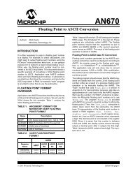
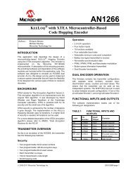
considerably simpler than those for a Li-Ion stack. Figure 1 shows<br />
a common approach to building and monitoring an HV stack.<br />
Cell-monitor ICs typically handle six or 12 cells. Currently, two<br />
application-specific special-purpose (ASSP) products are available<br />
from <strong>Analog</strong> Devices for cell monitoring: the AD7280, 1 intended<br />
for use as a primary monitor, is based on a high-speed multiplexed<br />
12-bit analog-to-digital converter; another device, intended<br />
for use as a backup, or redundancy monitor, is based on a series<br />
of window comparators. It is beyond the scope of this article to<br />
discuss these products in any depth, but it is worth noting how such<br />
devices communicate in a stack configuration. Each cell establishes<br />
the common-mode level for the measurement input from the one<br />
above it. A daisy-chain interface allows each individual AD7280 in<br />
a stack to communicate directly with the next AD7280 above it or<br />
below it (and thus pass digital information up or down the stack)<br />
without needing isolation. The SPI interface of the bottommost<br />
AD7280 is used to exchange data and control signals for the<br />
whole stack with the system microcontroller. It is at this point that<br />
high-voltage galvanic isolation must be employed to protect the<br />
low-voltage electronics elsewhere in the system.<br />
TOTAL BATTERY<br />
STACK VOLTAGE<br />
CURRENT<br />
SHUNT<br />
CELL<br />
MONITOR<br />
CELL<br />
MONITOR<br />
SAFETY<br />
SWITCH<br />
CELL<br />
MONITOR<br />
CELL<br />
MONITOR<br />
BIDIRECTIONAL<br />
DAISY-CHAIN BUS<br />
BETWEEN PACKS<br />
ISOLATION<br />
ISOLATION<br />
BIDIRECTIONAL<br />
COMMUNICATION BUS<br />
MICROPROCESSOR<br />
WITH CAN<br />
CONTROLLER<br />
CAN<br />
BUS<br />
SIGNAL<br />
CONDITIONING ISOLATION SIGNAL<br />
REPRESENTING<br />
STACK CURRENT<br />
Figure 1. Serial cell monitoring and isolation in a battery stack.<br />
In Figure 1, the string of serially connected cells has a switch or<br />
contactor placed in the middle of the string. Normally, this switch<br />
is closed at all times, whether the vehicle is in normal operation or<br />
parked. For vehicle maintenance or in emergency situations the<br />
switch is physically pulled or removed from its position to disable<br />
the stack voltage from appearing at the stack terminals. In order<br />
not to compromise the isolation provided by the open switch,<br />
it is important not to have any electronic components bridging<br />
the switch terminals. Thus, the top half of the stack should be<br />
electrically isolated from the bottom half with the switch open.<br />
This means that cell data from the top half of the stack must be<br />
communicated via its bottommost cell monitor across an isolation<br />
barrier to the microprocessor or microcontroller that is managing<br />
the flow of data into and out of the complete stack. Similarly,<br />
the bottom half of the stack must also be isolated from this<br />
microprocessor or microcontroller, so it has an identical isolation<br />
barrier to that of the top half.<br />
In addition to the cell monitors, a current monitor is positioned<br />
somewhere in the stack to measure and report on the stack<br />
current. This monitor is generally placed at the bottom of the<br />
stack; it also needs to be considered for isolation. Hall-effect<br />
<strong>Analog</strong> <strong>Dialogue</strong> Volume 43 Number 4 3
current sensors have inherent galvanic isolation and need no<br />
further isolation circuitry. If, however, the current sensor uses a<br />
shunt element, the associated shunt monitor circuitry will require<br />
an individual isolation barrier. Current sensing using shunts<br />
is becoming very popular; it is much more stable and accurate<br />
than, yet price competitive with, Hall-effect sensing. The<br />
use of low-value shunt resistors with low-cost high-resolution<br />
monitoring electronics—such as the AD820x and AD821x<br />
families of AEC-Q100 qualified current shunt monitors, which<br />
have shipped over 100M channels into automotive sockets to<br />
date—minimizes self-heating, a traditional objection to this<br />
approach. Thus, the system in Figure 1 requires three separate<br />
isolation barriers, unless the current-sense monitor can feed into<br />
the bottommost cell monitor, sharing its isolation barrier.<br />
Another popular approach to organizing cells in a battery stack is to<br />
group the battery packs into a series of electrically separate clusters<br />
(Figure 2). The bottommost monitor of each cluster communicates<br />
the local cell conditions across a dedicated isolation barrier back<br />
to the microcontroller on the nonisolated side.<br />
TOTAL BATTERY<br />
STACK VOLTAGE<br />
CURRENT<br />
SHUNT<br />
CELL<br />
MONITOR<br />
CELL<br />
MONITOR<br />
SAFETY<br />
SWITCH<br />
CELL<br />
MONITOR<br />
ISOLATION<br />
ISOLATION<br />
ISOLATION<br />
ISOLATED<br />
COMMUNICATION BUS<br />
CAN<br />
MICROPROCESSOR<br />
CELL<br />
BUS<br />
ISOLATION<br />
WITH CAN<br />
MONITOR<br />
CONTROLLER<br />
SIGNAL<br />
SIGNAL<br />
CONDITIONING ISOLATION REPRESENTING<br />
STACK CURRENT<br />
Figure 2. Battery stack with parallel access to packs.<br />
The increased use of digital isolators makes this approach<br />
somewhat more expensive than the system shown in Figure 1, but<br />
it offers the possibility of reading back all the cell data in a much<br />
shorter time, with all cell clusters simultaneously being asked<br />
to report on what the cell monitors are seeing within the packs.<br />
Another important benefit is that it allows backup monitoring to<br />
continue in the presence of problems developing with the daisy<br />
chain, such as broken wires or poor connector contacts. The data<br />
from “off-the-air” packs can still be determined by correlating the<br />
remaining pack voltages with the overall stack voltage.<br />
It does require more cabling, which can be problematic, since<br />
up to 75% of electromagnetic-compatibility (EMC) problems are<br />
considered to occur in relation to input/output (I/O) ports. The I/O<br />
port is an open gateway for electrostatic discharges or fast transient<br />
discharges or surges to enter a piece of equipment—and for<br />
interfering signals to escape, either by conduction of the spurious<br />
signals on the I/O lines or by radiation from the I/O cable. Adding<br />
more cables to a battery stack can reduce its EMC performance<br />
significantly unless careful attention is paid to the robustness of<br />
the signals and the communication protocol chosen. Because of<br />
this, the EMC performance of the I/O device connected to the<br />
port is crucial to the EMC of the entire equipment.<br />
The popular SPI communication protocol is suitable for<br />
communicating between devices on the same printed circuit board<br />
(PCB); but single-ended signals can be difficult to transmit reliably<br />
over 24 to 36 inches of wire, especially in a noisy environment.<br />
Where digital signals are to be transmitted off board, prudent system<br />
design might include differential transceivers, such as the ADM485.<br />
These transceivers can be powered from the low-side power source,<br />
so no power is drawn directly from the cells in the stack.<br />
Isolation Technology Is Key to Stack Communications<br />
For battery stack voltages to get higher in order to satisfy the<br />
demands of higher power electric motors found in heavier<br />
private vehicles, as well as light delivery trucks and vans, the<br />
number of cells in battery stacks must increase. In addition to<br />
increased numbers of serially connected cells, many battery<br />
packs now contain paralleled strings of cells in order to<br />
increase the ampere-hour (AH) capacity of the overall battery<br />
pack. The cells of each parallel string must be monitored—<br />
resulting in the collection of a lot of data. The cell monitor<br />
data associated with all of these cells must be transmitted<br />
back to the battery-measuring-system (BMS) microcontroller<br />
reliably and within the system loop time requirements set by<br />
the system integrators.<br />
Accordingly, the difficulties associated with providing reliable data<br />
communications across system-to-system boundaries have also<br />
increased. A key element to providing reliable communications across<br />
so many isolated boundaries inside a typical battery stack is automotivequalified<br />
isolation technology, now available from <strong>Analog</strong> Devices.<br />
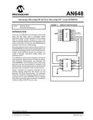
The basis of the technology is magnetic isolation, with transformers<br />
fabricated in a planar fashion using cost-effective standard CMOS<br />
processes (see Figure 3). This facilitates the integration of multiple<br />
isolation channels into a single component—or the integration of<br />
isolation channels with other semiconductor functions, such as line<br />
drivers and analog-to-digital converters (for example, the AD7400<br />
isolated ∑-∆ modulator).<br />
V DD1<br />
GND 1<br />
V IA<br />
V IB<br />
V OC<br />
V OD<br />
V E1<br />
GND 1<br />
1<br />
2<br />
3<br />
4<br />
5<br />
6<br />
7<br />
8<br />
ENCODE<br />
ENCODE<br />
DECODE<br />
DECODE<br />
DECODE<br />
DECODE<br />
ENCODE<br />
ENCODE<br />
16 V DD2<br />
15 GND 2<br />
14 V OA<br />
13 V OB<br />
12 V IC<br />
11 V ID<br />
10 V E2<br />
GND 2<br />
Figure 3. Functional block diagram of ADuM1402 quad isolator.<br />
These iCoupler ® digital isolators that, unlike optocouplers, do<br />
not degrade over the lifetime of the vehicle can accommodate<br />
the harsh operating conditions often encountered through the<br />
changing seasons. The recently released family of devices listed in<br />
Table 1—AEC-Q100 qualified to 125°C—uses the same materials<br />
as its well-established counterparts in the ADI family of iCoupler<br />
products, with more than 300 million channels of isolation shipped<br />
to date. The 2-channel, 3-channel, and 4-channel digital isolator<br />
9<br />
4 <strong>Analog</strong> <strong>Dialogue</strong> Volume 43 Number 4
Part Number<br />
Total<br />
Number<br />
of<br />
Channels<br />
Reverse<br />
Direction<br />
Options<br />
Table 1. AEC Q100-Qualified iCoupler Isolators<br />
Output<br />
Max<br />
Data<br />
Max<br />
Supply<br />
Rate<br />
Propagation Default EN Range<br />
(Mbps)<br />
Delay (ns)<br />
(V)<br />
Max<br />
Temperature<br />
(°C)<br />
Package<br />
Price<br />
($U.S.)<br />
0 1 2 H L Z<br />
2.5 kV rms Isolation<br />
ADuM120xA/WS<br />
• • — 1 150 • — — 3.0 to 5.5 125 8-lead SOIC_N 1.21/2.13<br />
ADuM120xB/WT 2 • • — 10 50 • — — 3.0 to 5.5 125 8-lead SOIC_N 1.76/3.11<br />
ADuM120xC/WU • • — 25 45 • — — 3.0 to 5.5 125 8-lead SOIC_N 2.44/4.30<br />
ADuM130xA/WS<br />
• • — 1 100 • — • 3.0 to 5.5 125 16-lead SOIC_W 1.61/2.42<br />
3<br />
ADuM130xB/WT • • — 1 32 • — • 3.0 to 5.5 125 16-lead SOIC_W 2.42/3.62<br />
ADuM140xA/WS<br />
• • • 1 100 • — • 3.0 to 5.5 125 16-lead SOIC_W 2.15/3.22<br />
4<br />
ADuM140xA/WS • • • 10 50 • — • 3.0 to 5.5 125 16-lead SOIC_W 2.22/4.82<br />
families in the table have data rates up to 25 Mbps and propagation<br />
delays as low as 32 ns.<br />
The planar transformers are inherently bidirectional; therefore,<br />
signals can pass in either direction. All possible combinations of<br />
drive and receive channels within the total number of channels are<br />
available. For instance, the 2-channel ADuM120xW, 3-channel<br />
ADuM130xW, and 4-channel ADuM140xW, alone or together,<br />
offer seven different channel configurations (4-0, 3-1, 2-2, 3-0,<br />
2-1, 2-0, 1-1), ensuring an optimized solution for all situations.<br />
Figure 4 summarizes the various configurations available.<br />
Two of the most distinguishing features of the iCoupler technology<br />
are the ability to support high data rates and to operate with low<br />
supply currents. The supply current drawn by an iCoupler channel<br />
is largely a function of the data rate it is carrying. For 3-V operation,<br />
the total power supply current—for both sides and all four channels<br />
of the ADuM140xWS—is 1.6 mA typical (4 mA maximum) at a<br />
data rate up to 2 Mbps. Low-power operation is important since,<br />
on the isolated or “hot” side of the ADuM140xWS, the power<br />
comes from the cells themselves through a voltage regulator. The<br />
monitors are also powered from this same voltage source, so the less<br />
power taken by all elements of the monitoring and communicating<br />
circuitry the better. All isolation products are available in small,<br />
low-profile, surface-mount 8-lead SOIC_W or 16-lead SOIC_W<br />
packages and come with safety certifications from UL, CSA, and<br />
VDE. They feature isolation ratings up to 2.5 kV rms and working<br />
voltages up to 400 V rms.<br />
iCoupler Technology Begets isoPower Devices: Integrated,<br />
Isolated Power<br />
One of the most exciting developments of iCoupler technology is<br />
the integration of both power transmission and signal transmission<br />
within the same package. With microtransformers similar to those<br />
used for signal isolation, power can now be transferred across an<br />
isolation barrier—allowing fully integrated isolation for remotely<br />
powering the data isolators in the battery packs. Local power is<br />
supplied to an oscillating circuit that switches current through a<br />
chip-scale air core transformer. Power transferred to the isolated<br />
side is rectified and regulated to either 3.3 V or 5 V. The isolatedside<br />
controller provides feedback regulation of the output by<br />
creating a PWM control signal that is sent back to the local side<br />
by a dedicated iCoupler data channel. The PWM control signal<br />
modulates the oscillator circuit to control the power being sent to<br />
the isolated side. The use of feedback permits significantly higher<br />
power and efficiency.<br />
The ADuM540xW devices are 4-channel digital isolators that<br />
include an isoPower ® , integrated, isolated dc-to-dc converter, which<br />
provides up to 500 mW of regulated, isolated power at either 5.0 V<br />
from a 5.0-V input supply or 3.3 V from a 3.3-V supply. As with<br />
the standard iCoupler devices, a variety of channel configurations<br />
and data rates is available. Because an isoPower device uses<br />
high-frequency switching elements to transfer power through its<br />
transformer, special care must be taken during PCB layout to<br />
meet emissions standards. Refer to AN-0971 Application Note,<br />
Recommendations for Control of Radiated Emissions with isoPower<br />
Devices, for details on board-layout considerations. The ADuM540x<br />
family is currently undergoing AEC-Q100 qualification.<br />
References<br />
1<br />
Information on all A DI components can be found at<br />
www.analog.com.<br />
Author<br />
John Wynne [john.wynne@analog.com] is a precision converter<br />
marketing manager at <strong>Analog</strong> Devices.<br />
ADuM1200W ADuM1201W ADuM1300W ADuM1301W ADuM1400W ADuM1401W<br />
ADuM1402W<br />
Figure 4. Seven different configurations with the ADuM120xW/ADuM130xW/ADuM140xW.<br />
<strong>Analog</strong> <strong>Dialogue</strong> Volume 43 Number 4 5
Synchronizing Device Clocks<br />
Using IEEE 1588 and Blackfin<br />
Embedded Processors<br />
By Jiang Wu and Robert Peloquin<br />
Introduction<br />
The IEEE 1588 standard, introduced in 2002, defines a protocol<br />
to synchronize distributed clocks on a network. It is becoming<br />
the preferred clock synchronization method for many different<br />
applications, including test and measurement, telecommunications,<br />
and multimedia streaming. This standardized method for<br />
synchronizing clocks is cost-effective, supports heterogeneous<br />
systems, and provides nanosecond-level synchronization precision.<br />
This article provides an introduction to both the original<br />
IEEE 1588-2002 standard and the enhancements incorporated<br />
as part of the updated IEEE 1588-2008 version. Dedicated<br />
hardware support for IEEE 1588 has been integrated into the<br />
ADSP-BF518 1 Blackfin ® embedded processor because of the<br />
increasing importance of IEEE 1588 in some of its targeted<br />
applications. An overview of its capabilities is provided, followed<br />
by an example showing clock synchronization performance results<br />
obtained by an ADSP-BF518 processor solution.<br />
What Time Is It<br />
It is common for a system to need to maintain its own sense of time<br />
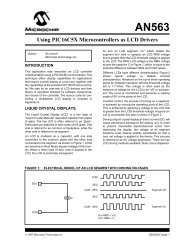
using a local oscillator. Figure 1 shows how hardware and software<br />
combine to generate time information within a system.<br />
OSCILLATOR<br />
HARDWARE<br />
DIVIDER<br />
COUNTER<br />
FREQUENCY<br />
CONVERSION<br />
EPOCH<br />
NUMBER OF<br />
PULSES<br />
H:M:S TIME<br />
SOFTWARE<br />
TIME<br />
HOUR:MIN:SEC<br />
API FUNCTIONS<br />
CLOCK OUTPUT<br />
LOCAL TIME SYSTEM<br />
APPLICATION<br />
APPLICATION HARDWARE<br />
APPLICATION SOFTWARE<br />
Figure 1. Local timekeeping.<br />
This time information can be used by both hardware and software<br />
resources within the system. In hardware, one or more physical<br />
clock signals (clock outputs) are derived from the oscillator’s clock<br />
and can be used to drive or trigger other parts of the system. The<br />
time maintained in software is typically referred to as system time.<br />
The system time can be represented in the form of numbers of clock<br />
pulses or in second/nanosecond notation. The system software<br />
derives the time from the number of oscillator clock pulses and<br />
its frequency information, and provides application-programminginterface<br />
(API) functions that other parts of the software use to<br />
retrieve and set the time. If an absolute time is desired, the provided<br />
time is associated with a predefined epoch, which identifies a<br />
reference point in time.<br />
Synchronize Your Watches<br />
Many applications require two independent devices to operate in<br />
a synchronized fashion. If each device were to rely solely on its<br />
own oscillator, differences between the specific characteristics<br />
and operating conditions of the individual oscillators would limit<br />
the ability of the clocks to operate synchronously. Some possible<br />
simplistic solutions to address these limitations include:<br />
• All the devices could use a single physical oscillator. This is only feasible<br />
for distributed systems in close proximity; a high-frequency clock<br />
signal cannot be reliably delivered over a long distance.<br />
• All the devices could utilize oscillators with nearly identical<br />
characteristics. This approach is impractical due to the difficulty<br />
of acquiring nearly identical oscillators and keeping them from<br />
drifting apart over time. More importantly, each oscillator will<br />
be subjected to different operating conditions.<br />
• If all the devices are interconnected via a communications network<br />
such as Ethernet, they can dynamically adjust their individual clocks<br />
to a single “master” clock by exchanging time messages over the<br />
network. With network time protocol (NTP), the traditional time<br />
synchronization protocol, every device in the system adjusts<br />
its clock according to the time information it retrieves from<br />
an NTP time server. However, this protocol can only achieve<br />
synchronization accuracy on the order of milliseconds.<br />
IEEE 1588 defines a newer protocol capable of nanosecond<br />
synchronization accuracy. How it can achieve this level of clock<br />
synchronization is discussed in the following sections.<br />
What IEEE 1588 Does<br />
The IEEE 1588 standard defines a protocol for time-synchronizing<br />
devices that are geographically dispersed but interconnected by<br />
some form of communications technology, for example, Ethernet.<br />
By exchanging timing messages between devices they can maintain<br />
the same absolute system time, which is represented in seconds<br />
and nanoseconds.<br />
An intuitive way to achieve this goal is for one device, which has<br />
the “best” (most accurate) clock, and is designated as the masterclock<br />
device, to broadcast its time to the other devices. The other<br />
devices will adjust their times to match the time sent by the master<br />
clock. This solution has several limitations, though:<br />
1. The master-clock device cannot broadcast the time at<br />
infinitesimal intervals, so the “slave” clock devices have to use<br />
their own independent and “inferior” oscillators to interpolate<br />
the time points between two broadcasts from the master-clock<br />
device. This results in degraded synchronization during the<br />
time between updates from the master clock.<br />
2. Delays inevitably exist on the broadcast path, with magnitudes<br />
depending on the communications technology—the time that<br />
a physical signal takes to travel along a wire from one device to<br />
another, for example. This delay results in an additional offset<br />
between the master clock and each slave clock.<br />
3. Differences among the broadcast paths between the masterclock<br />
device and each slave-clock device will further degrade<br />
the synchronization between individual slave-clock devices.<br />
IEEE 1588 specifies a protocol that solves the second and third<br />
problems by measuring path delay. It also allows the slave clock<br />
to be adjusted to match the master clock’s pace so as to mitigate<br />
the first problem. Where possible, the first problem can be<br />
further reduced by using smaller broadcasting intervals and<br />
higher-quality oscillators.<br />
How IEEE 1588 Measures Communication Delay<br />
IEEE 1588-2002 2 defines four messages to measure the<br />
communication delay of the forward (master to slave) and<br />
backward (slave to master) paths: Sync, Followup, DelayReq, and<br />
DelayResp. The newer version, IEEE 1588-2008, 3 provides further<br />
mechanisms to measure the peer-to-peer delay with three additional<br />
messages: PdelayReq, PdelayResp, and PdelayRespFollowup.<br />
6 <strong>Analog</strong> <strong>Dialogue</strong> Volume 43 Number 4
Among these messages, Sync, DelayReq, PdelayReq, and<br />
PdelayResp, so-called event messages, must be time-stamped<br />
(recording the local time) when they leave and arrive at a device.<br />
There are two techniques to time-stamp packets:<br />
1. Software time-stamp occurs when the messages are handled<br />
by the software. Usually occurring in the message’s receive/<br />
transmit interrupt service routine (ISR), the time-stamp is the<br />
current value of the system time.<br />
2. Hardware time-stamp occurs when the messages physically<br />
arrive at or leave the device. The time-stamp operation is<br />
executed by hardware, which maintains its own continuous<br />
time information.<br />
Either time-stamp method is acceptable in IEEE 1588, but a<br />
hardware time-stamp can provide significantly better precision,<br />
as will be shown below.<br />
Delay from Master-Clock Device to Slave-Clock Device<br />
The messages Sync and Followup are sent by the master-clock<br />
device; it is a slave-clock device’s responsibility to receive them<br />
and calculate the communication path delay from the master-clock<br />
device to the slave-clock device.<br />
In Figure 2, at time Tm1, the master-clock device software<br />
reads the current local system time (Tm1, the software timestamp),<br />
inserts it into a Sync message, and sends the message<br />
out. The message leaves the master-clock device at a later<br />
time, Tm1', which is the hardware time-stamp. It arrives at<br />
slave-clock hardware at Ts1' (slave-clock device local time),<br />
and is received by the slave-clock device software at a later<br />
time, Ts1. The software will read the hardware time-stamp<br />
to get Ts1'. If there is no communication delay, Ts1' should<br />
be equal to (Tm1' + Tms), where Tms is the time difference<br />
between master clock and slave clock. The protocol’s ultimate<br />
goal is to compensate for this difference.<br />
MASTER<br />
SOFTWARE<br />
MASTER<br />
SENDS SYNC<br />
Tm1<br />
Tm2<br />
MASTER<br />
SENDS<br />
FOLLOWUP<br />
SOFTWARE<br />
TIME-STAMP<br />
POINT<br />
MASTER<br />
HARDWARE<br />
Tm2'<br />
COMMUNICATION<br />
PATH<br />
Tm1'<br />
HARDWARE<br />
TIME-STAMP<br />
POINT<br />
Ts2'<br />
HARDWARE<br />
TIME-STAMP<br />
POINT<br />
SLAVE<br />
HARDWARE<br />
Ts1'<br />
SOFTWARE<br />
TIME-STAMP<br />
POINT<br />
SLAVE<br />
SOFTWARE<br />
SYNC<br />
CARRIES Tm1<br />
SLAVE GETS Ts1'<br />
Ts1<br />
Ts2<br />
FOLLOWUP<br />
CARRIES Tm1'<br />
SLAVE GETS Tm1'<br />
Figure 2. Measuring communication delay between<br />
master-clock and slave-clock devices.<br />
After the Sync message has been sent, the master-clock device<br />
software reads the Sync message’s departure time, Tm1', through<br />
the time-stamping unit, inserts it into a Followup message, and<br />
sends that message out at Tm2. This message is received by slaveclock<br />
device software at Ts2. At this point, the slave-clock device<br />
software has the two times, Ts1' (Sync arrival time) and Tm1'<br />
(Sync departure time). The master-to-slave path delay, Tmsd, is<br />
determined by Equation 1.<br />
Delay from Slave-Clock Device to Master-Clock Device<br />
The DelayReq message is sent by the slave-clock devices, and the<br />
DelayResp message is sent by the master-clock device in response.<br />
With these messages, the slave-clock devices can calculate the<br />
communication path delay from the slave-clock device to the<br />
master-clock device.<br />
At time Ts3 (Figure 3), the slave-clock device software reads<br />
the current local system time (Ts3), inserts it into a DelayReq<br />
message, and sends the message out. After the message is sent,<br />
the slave-clock device software reads the time-stamp to get the<br />
departure time of the message, Ts3', and waits for the response<br />
from the master-clock device.<br />
SLAVE<br />
SOFTWARE<br />
SLAVE SENDS<br />
DELAYREQ<br />
Ts3<br />
Ts4<br />
SLAVE GETS Tm3'<br />
SOFTWARE<br />
TIME-STAMP<br />
POINT<br />
SLAVE<br />
HARDWARE<br />
Ts4'<br />
COMMUNICATION<br />
PATH<br />
Ts3'<br />
HARDWARE<br />
TIME-STAMP<br />
POINT<br />
Tm3'<br />
Tm4'<br />
HARDWARE<br />
TIME-STAMP<br />
POINT<br />
MASTER<br />
HARDWARE<br />
SOFTWARE<br />
TIME-STAMP<br />
POINT<br />
MASTER<br />
SOFTWARE<br />
Tm4<br />
(1)<br />
MASTER<br />
RECEIVES DELAYREQ<br />
SAVES Tm3'<br />
Tm3<br />
MASTER<br />
SENDS DELAYRESP<br />
WHICH CARRIES Tm3'<br />
Figure 3. Measuring slave-master communication delay.<br />
The DelayReq message arrives at the master-clock device at a later<br />
time, Tm3', and is processed by the master software at Tm3. The<br />
software then reads the time-stamp to get the arrival time, Tm3',<br />
puts it into the DelayResp message, and sends to a slave-clock<br />
device at Tm4. When the slave-clock device software receives<br />
the DelayResp message at Ts4, it can extract the time, Tm3', and<br />
calculate the slave-to-master delay, Tsmd, by Equation 2.<br />
In both Equation 1 and Equation 2, there is an unknown<br />
variable, the master-slave time difference, Tms. So it is not<br />
possible to get either Tmsd or Tsmd individually. However,<br />
if one makes the usually acceptable assumption that the<br />
communication path is symmetric<br />
(3)<br />
—a key assumption for IEEE 1588 to work correctly—then, adding<br />
Equation 1 and Equation 2 gives<br />
All these calculations are performed by the slave-clock devices,<br />
since it is they who seek to synchronize themselves to the masterclock<br />
device. They get Tm1' from master-clock device’s Followup<br />
message, Ts1' from their Rx (reception) time-stamping, Ts3'<br />
from their Tx (transmission) time-stamping, and Tm3' from the<br />
master-clock device’s DelayResp message.<br />
(2)<br />
(4)<br />
<strong>Analog</strong> <strong>Dialogue</strong> Volume 43 Number 4 7
How to Calculate the Time Difference Between a Slave Clock and<br />
Master Clock<br />
Once the communication path delay, Td, is obtained, the slavemaster<br />
time difference is easy to calculate, using either Equation 1<br />
or Equation 2, as shown in Equation 5 and Equation 6.<br />
How to Adjust the Time of a Slave-Clock Device<br />
With the time difference from the master clock known, each slaveclock<br />
device needs to adjust its own local time to match the master<br />
clock. This task has two aspects. First, slave-clock devices need to<br />
adjust their absolute time by adding the time difference to make<br />
their time perfectly match the master-clock time at this moment.<br />
Then, each slave-clock device needs to adjust its clock frequency<br />
to match the frequency of the master clock. We cannot rely on the<br />
absolute time alone, since the time difference is applied only at a<br />
certain period and could be either positive or negative; as a result,<br />
the adjustment will make the slave-clock time jumpy or even run<br />
backward. So, in practice, the adjustment takes two steps.<br />
1. If the time difference is too big, for example, larger than<br />
one second, absolute time adjustment is applied.<br />
2. If the time difference is small, a percentage change of frequency<br />
is applied to slave clocks.<br />
Generally speaking, the system becomes a control loop, where<br />
master-clock time is the reference command, slave-clock time is<br />
the output tracking the master-clock time, and their difference<br />
drives the adjustable clock. PID control, which is commonly<br />
used by many IEEE 1588 implementations, could be used to<br />
achieve specific tracking performance. Figure 4 illustrates this<br />
control loop.<br />
MASTER<br />
TIME<br />
+<br />
–<br />
IEEE 1588 CONTROL LOOP<br />
CONTROL LAW<br />
ADJUSTABLE<br />
CLOCK<br />
Figure 4. IEEE 1588 control loop.<br />
(5)<br />
(6)<br />
SLAVE<br />
TIME<br />
Peer-to-Peer Delay<br />
The revised version, IEEE 1588-2008, introduces a new<br />
mechanism for measuring path delay, called peer-to-peer (P2P)<br />
delay. By contrast, the master-slave mechanism discussed in the<br />
previous sections is end-to-end (E2E) delay. In an IEEE 1588-2008-<br />
capable network, a master-clock device can be linked to slave-clock<br />
devices either directly or through multiple hops (stages). The E2E<br />
delay is actually the total delay from a master-clock device to a<br />
slave-clock device, including all the hops in between. However,<br />
the P2P delay is limited to two directly connected devices. The<br />
overall delay along the path is the sum of the P2P delay of all the<br />
hops. From the perspective of preserving path symmetry, the P2P<br />
mechanism provides better accuracy.<br />
As noted earlier, IEEE 1588-2008 includes three additional<br />
messages, PdelayReq, PdelayResp, and PdelayRespFollowup,<br />
to measure P2P delay. They work in a manner similar to that<br />
explained above. Reference 3 provides more details.<br />
Factors Affecting Synchronization Performance<br />
Well-designed IEEE 1588 devices are capable of achieving<br />
highly accurate clock synchronization, but it is important to<br />
recognize the key factors that directly affect performance.<br />
Some of these include:<br />
1. Path delay: As noted earlier, the path delay measurement of<br />
IEEE 1588 assumes that the communication-path delays are<br />
symmetrical, that is, the transmission delay of the forward path<br />
is equal to the reverse transmission delay. In addition, the delay<br />
should not vary during the delay measurement. Variation in<br />
delay during measurement will produce asymmetry and delay<br />
jitter, which will have a direct impact on the synchronization<br />
precision. While delay symmetry and jitter cannot be controlled<br />
outside the boundaries of an IEEE 1588 device, both path<br />
symmetry and jitter can be improved within the device if<br />
measurements are based on hardware time-stamping. Hardware<br />
time-stamping eliminates the significant jitter resulting from<br />
software time-stamping—due to interrupt latency, context<br />
switch, and thread scheduling.<br />
2. Drift and jitter characteristics of clocks: The frequency<br />
and phase of the master clock represent the inputs of the<br />
tracking control system, and the slave clock is the control<br />
object. Any time-varying behavior of the master clock will<br />
act as a disturbance to the control system and result in both<br />
steady-state- and transient errors. Clocks with less drift and<br />
jitter will, therefore, improve synchronization accuracy.<br />
3. Control law: The control method determines how the errors in<br />
the slave-clock-device time are corrected in the adjustment of<br />
the slave clock. The control-law parameters, including settling<br />
time, overshoot, and steady-state error, will directly affect clock<br />
synchronization performance.<br />
4. Resolution of the clocks: As shown in Figure 1, the resolution<br />
of the local time is determined by the frequency of the clock; the<br />
minimum increment of time is one period of the clock signal.<br />
The IEEE 1588 protocol runs on a time with a resolution of<br />
1 ns for IEEE 1588-2002 and 2 –16 ns for IEEE 1588-2008. It<br />
is not practical to have a clock of 2 16 (!) GHz (or even 1 GHz).<br />
The quantization of the local clocks is expected to affect the<br />
precision of local time measurement and control.<br />
5. How often Sync messages are issued: The frequency<br />
with which the slave clocks are updated ultimately affects<br />
the precision of synchronization. A longer period usually<br />
leads to larger time errors observed at the next Sync, since<br />
the time error is the integral accumulation of the slave-clock<br />
frequency error.<br />
6. How often delay measurement is conducted: Delay<br />
measurement is performed periodically, at intervals based on<br />
the expectation that the delay does not change significantly<br />
between adjacent samples. If the IEEE 1588 network experiences<br />
large delay variations, then increasing the delay-measurement<br />
frequency will improve clock-synchronization performance.<br />
Which Is the Master-Clock<br />
Having considered how to accurately determine the time difference<br />
between master-clock devices and slave-clock devices, a relevant<br />
question is how to determine which device, among possibly hundreds<br />
of interconnected devices, will serve as the master clock.<br />
IEEE 1588 defines a method called the best master clock (BMC)<br />
algorithm to choose the master clock device. For this approach,<br />
every device of an IEEE 1588 network maintains a data set<br />
describing the nature, quality, stability, unique identifier, and<br />
preference of its local clock. When a device joins an IEEE 1588<br />
network, it will broadcast the dataset of its own clock and receive<br />
the datasets from all other devices. Using the datasets of all the<br />
participating devices, every device runs the same BMC algorithm<br />
to decide on the master clock and its own future status (master<br />
clock or slave clock). Because the same algorithm is executed<br />
independently by all the devices on the same data, all will come<br />
8 <strong>Analog</strong> <strong>Dialogue</strong> Volume 43 Number 4
to the same conclusion without requiring any negotiation among<br />
them. More information about the details of the BMC algorithm<br />
can be found in References 2 and 3.<br />
ADSP-BF518 Processor’s Support for IEEE 1588<br />
The <strong>Analog</strong> Devices ADSP-BF518 processor recently joined ADI’s<br />
Blackfin DSP family. Like its predecessor, the ADSP-BF537, 4 it<br />
has a built-in Ethernet media-access controller (EMAC) module. Its<br />
capability to support EMAC functionality within the IEEE 1588<br />
standard is extended by an additional TSYNC module, as well as<br />
extra features to support a wide range of IEEE 1588 applications<br />
on Ethernet. Figure 5 shows the block diagram of the TSYNC<br />
module. The ADSP-BF51x Blackfin Processor Hardware Reference<br />
provides additional information. 5<br />
CLOCK<br />
OUT<br />
EXTERNAL<br />
CLOCK<br />
MII/RMII<br />
CLOCK<br />
SYSTEM<br />
CLOCK<br />
EVENT<br />
FLAG<br />
MII Tx<br />
MII Rx<br />
CLOCK OUTPUT<br />
DRIVER<br />
CLOCK SOURCE<br />
MUX<br />
EVENT DETECTION<br />
PTP Tx EVENT<br />
PACKET DETECTION<br />
PTP Rx EVENT<br />
PACKET DETECTION<br />
ADSP-BF518<br />
TSYNC MODULE<br />
ADDEND<br />
ADJUSTABLE<br />
CLOCK<br />
Tx<br />
TIMESTAMPING<br />
Rx<br />
TIMESTAMPING<br />
PPS<br />
GENERATOR<br />
LOCAL TIME<br />
COUNTER<br />
ALARM<br />
GENERATOR<br />
INTERRUPT<br />
PPS<br />
OUTPUT<br />
INTERRUPT<br />
REQUEST<br />
Figure 5. Block diagram of the ADSP-BF518 processor's<br />
TSYNC module.<br />
Packet Detection<br />
The ADSP-BF518 processor can detect and provide hardware<br />
time-stamps for all IEEE 1588 event messages, including both<br />
incoming and outgoing packets. The precision of an IEEE 1588<br />
system depends significantly on both the accuracy of the eventmessage<br />
time-stamps and on where they are taken, as these affect<br />
the requirement for symmetry and constancy of path delay. The<br />
ADSP-BF518's TSYNC module keeps monitoring the hardware<br />
interface between the MAC controller and the Ethernet physical<br />
interface transceiver (PHY), that is, the media independent interface<br />
(MII), and produces a hardware time-stamp whenever it detects<br />
an event message—a capability promoting higher synchronization<br />
precision with the ADSP-BF518.<br />
The detection of event messages, designed to be programmable,<br />
can basically be configured to support either IEEE 1588-2002<br />
(default) or IEEE 1588-2008. Furthermore, this programmability<br />
allows for the support of future versions of IEEE 1588, as well as<br />
other general protocols that require time-stamping—including<br />
being configured to time-stamp every Ethernet packet coming<br />
into and out of the processor.<br />
Flexible Clock Sources<br />
The properties of local clocks are important for the performance<br />
of an IEEE 1588 system. To satisfy requirements of a variety of<br />
applications, the ADSP-BF518 processor allows three options for<br />
the local clock source: system clock, external clock, or Ethernet<br />
clock. If the application has a specific clock requirement, it can<br />
choose external clock and provide a customized clock source. The<br />
Ethernet clock option can offer good precision if the master-clock<br />
devices and the slave-clock devices are connected back-to-back,<br />
since the clock is inferred from the Ethernet lines, and the two<br />
devices are running on the same clock. A general application can<br />
take the processor’s system clock as its clock source.<br />
The selected source clock is also driven by the TSYNC module as<br />
an output of the processor, via the specific pin Clockout, to be used<br />
by other parts of the system for local time information.<br />
PPS Output<br />
The pulse-per-second (PPS) signal is a physical representation<br />
of time information. It is nominally a 1-Hz signal with a pulse<br />
at each one-second transition of time. It can be used to control<br />
local devices or to provide an auxiliary time channel in case of<br />
network failure. It can also be used in testing. The phase difference<br />
between PPS signals at two devices is a physical measurement of<br />
their time offset.<br />
The ADSP-BF518 processor provides a flexible PPS output. It<br />
uses a programmable start time (PPS_ST) and period (PPS_P)<br />
to generate a signal with pulses occurring at the times<br />
(PPS _ ST + n × PPS_P), where n = 1, 2, 3… In the basic<br />
usage, the PPS signal can be created simply by setting<br />
PPS _ P to 1 second, and PPS_ST to any future instant as a<br />
multiple of seconds. This PPS output capability allows for its use<br />
as the reference for generation of a periodic signal with a fully<br />
programmable frequency and start time.<br />
Auxiliary Snapshot<br />
Some applications may need to time-stamp a certain event<br />
indicated by the toggle of a flag signal. The ADSP-BF518's<br />
TSYNC module facilitates this request by providing an auxiliary<br />
snapshot function, using a dedicated pin to accept an external flag.<br />
Toggling the flag will trigger the module to capture the current<br />
local time in a time-stamp register for software to access.<br />
Alarm<br />
If an application needs to execute a task at a specific time, it can<br />
make use of the alarm feature of the TSYNC module. This feature<br />
allows an absolute local time to be set so as to trigger a processor<br />
interrupt when the time arrives. The software can then service<br />
the interrupt and run the task.<br />
Adjustable Clock<br />
The adjustable clock of the TSYNC module is an addend-based<br />
clock. As shown in Figure 6, it takes a fixed input clock signal and<br />
outputs a “pulse-steal” version of the input: the value of addend is<br />
added to the accumulator at each input clock, and each time the<br />
accumulator overflows the carry bit drives the local-time counter,<br />
which gives the local time in terms of the number of pulses counted.<br />
The frequency of the local clock can be adjusted by changing the<br />
addend, since the addend decides how often the accumulator<br />
overflows, and so how often the local-time counter increments. If<br />
the frequency of the input clock is F in , and the value of addend is<br />
A, then the local clock frequency will be<br />
32-BIT<br />
ADDEND<br />
INPUT CLOCK<br />
32-BIT<br />
ACCUMULATOR<br />
ADDEND-BASED ADJUSTABLE CLOCK<br />
SUM<br />
CARRY<br />
SUM<br />
64-BIT<br />
LOCAL TIME<br />
COUNTER<br />
32-BIT<br />
OFFSET<br />
Figure 6. Addend-based adjustable clock.<br />
(7)<br />
<strong>Analog</strong> <strong>Dialogue</strong> Volume 43 Number 4 9
Implementation of IEEE 1588 on the ADSP-BF518 Processor<br />
A complete IEEE 1588-2008-compliant system was built on an<br />
ADSP-BF518 processor as shown in Figure 7.<br />
ADSP-BF518<br />
PROCESSOR<br />
PROCESSOR<br />
SYSTEM CLOCK<br />
PPS<br />
OUTPUT<br />
IEEE 1588 PTP<br />
SYSTEM<br />
TSYNC MODULE<br />
DRIVER SOFTWARE<br />
TSYNC MODULE<br />
HARDWARE<br />
APPLICATION<br />
IEEE 1588-2008 STACK SOFTWARE<br />
ETHERNET PHY<br />
ETHERNET<br />
MAC CONTROLLER<br />
DRIVER SOFTWARE<br />
MAC CONTROLLER<br />
HARDWARE<br />
Figure 7. An implementation of IEEE 1588 on the ADSP-BF518.<br />
The TSYNC module of the processor detects incoming and<br />
outgoing IEEE 1588 messages and uses hardware to time-stamp<br />
event messages. The IEEE 1588 stack software, provided<br />
by IXXAT (IXXAT Automation GmbH), implements the<br />
message-exchange protocol required by the standard. It makes<br />
use of the TSYNC driver to read, write, and adjust the TSYNC<br />
clock, and uses the MAC controller driver to send and receive<br />
messages on the Ethernet MAC layer (Layer 2 of the Open-<br />
Systems Interconnection Model). It also implements the control<br />
law and filtering of P2P delay measurements. The Ethernet PHY<br />
is National Semiconductor DP83848, 6 chosen because of its low<br />
jitter delay characteristics. For simplicity, the processor’s system<br />
clock (80 MHz) was chosen to be the TSYNC module clock source.<br />
NUMBER OF SAMPLES<br />
1400<br />
1200<br />
1000<br />
800<br />
600<br />
400<br />
200<br />
0<br />
–60 –40 –20 0 20 40 60<br />
ERROR (ns)<br />
Figure 8. Histogram of slave-clock error of an IEEE 1588<br />
system on ADSP-BF518.<br />
Figure 8 shows the clock synchronization performance of the<br />
device as a histogram of the measured error between two identical<br />
ADSP-BF518 IEEE 1588 systems. 6938 measurements were taken<br />
over a period of approximately 1700 seconds. The resulting mean<br />
error is 0.015 ns, and the standard deviation is 12.96 ns. A Sync<br />
message interval of 0.25 seconds was used for this test.<br />
Conclusion<br />
The IEEE 1588 standard provides a highly accurate, low-cost<br />
method for synchronizing distributed clocks. While hardware<br />
support is not explicitly required for IEEE 1588, hardware-assisted<br />
message detection and time stamping is critical to achieve the<br />
highest level of synchronization precision. The ADSP-BF518<br />
processor provides hardware support for both IEEE 1588-2002<br />
and IEEE 1588-2008, including features that can support a wide<br />
range of applications. High-precision clock synchronization has<br />
been demonstrated by implementing IEEE 1588 technology using<br />
the ADSP-BF518 processor and the IXXAT IEEE 1588-2008<br />
protocol software.<br />
References<br />
1<br />
ADSP-BF518 data sheet. http://www.analog.com/en/embeddedprocessing-dsp/blackfin/adsp-bf518/processors/product.html.<br />
2<br />
IEEE Std. 1588-2002. IEEE Standard for a Precision Clock<br />
Synchronization Protocol for Networked Measurement and Control<br />
Systems. http://ieee1588.nist.gov/PTTI_draft_final.pdf.<br />
3<br />
IEEE Std. 1588-2008. IEEE Standard for a Precision Clock<br />
Synchronization Protocol for Networked Measurement and Control<br />
Systems. http://ieee1588.nist.gov.<br />
4<br />
ADSP-BF537 data sheet. http://www.analog.com/en/embeddedprocessing-dsp/blackfin/adsp-bf537/processors/product.html.<br />
5<br />
ADSP-BF51x Blackfin Processor Hardware Reference Preliminary,<br />
Revision 0.1 (Preliminary). January 2009. <strong>Analog</strong> Devices, Inc.<br />
http://www.analog.com/static/imported-files/processor_manuals/<br />
bf51x_hwr_rev_0-1.pdf.<br />
6 AN-1507: DP83848 and DP83849 100Mb Data Latency. 2006.<br />
National Semiconductor Corporation. http://www.national.com/<br />
an/AN/AN-1507.pdf.<br />
Authors<br />
Dr. Jiang Wu [jiang.wu@analog.com] joined<br />
<strong>Analog</strong> Devices in 2006, where he works<br />
on real-time embedded systems and digital<br />
processing. In 2004, he received a PhD in<br />
electrical engineering from the University of<br />
Rhode Island. In 1996 and 1993, respectively, he<br />
received MS and BS degrees in automation, both<br />
from the Beijing Institute of Technology. His<br />
graduate research work was on modeling and instrumentation<br />
of biomedical systems. Prior to ADI, Jiang worked as a system<br />
engineer at Vivoda Communications.<br />
Robert Peloquin [robert.peloquin@analog.com]<br />
joined <strong>Analog</strong> Devices in 2000. As a senior<br />
applications engineer, he contributes to many<br />
different aspects of ADI's digital signal processor<br />
solutions. Some recent areas include Ethernet<br />
AVB and IEEE 1588. Prior to joining ADI, Bob<br />
worked at the Naval Undersea Warfare Center<br />
performing applied research for unmanned<br />
undersea vehicle technologies. He holds a BSEE degree from<br />
Syracuse University and a MSEE degree from the University<br />
of Massachusetts, Dartmouth.<br />
10 <strong>Analog</strong> <strong>Dialogue</strong> Volume 43 Number 4
Designing High-Performance<br />
Phase-Locked Loops with<br />
High-Voltage VCOs<br />
By Austin Harney<br />
Introduction<br />
The phase-locked loop (PLL) is a fundamental building block<br />
of modern communication systems. PLLs are typically used to<br />
provide the local-oscillator (LO) function in a radio receiver or<br />
transmitter; they are also used for clock-signal distribution and<br />
noise reduction—and, increasingly, as the clock source for highsampling-rate<br />
analog-to-digital (A/D) conversion.<br />
As feature size has shrunk in integrated-circuit processing,<br />
device supply voltages, including supplies for PLLs and other<br />
mixed-signal functions, have followed downward. However,<br />
the practical technology for voltage-controlled oscillators (VCOs),<br />
a critical element of PLLs, has not decreased as rapidly. Many<br />
high-performance VCO designs are still implemented with discrete<br />
circuitry that may require supply voltages as great as 30 V. This<br />
imposes a challenge for today’s PLL or RF system designer: to<br />
interface the low-voltage PLL IC with a higher voltage VCO. The<br />
level-shifting interface is typically implemented using active filter<br />
circuitry—to be discussed below.<br />
This article will consider the basics of PLLs, examine the current<br />
state of the art in PLL design with high voltage VCOs, discuss<br />
the pros and cons of typical architectures, and introduce some<br />
alternatives to high-voltage VCOs.<br />
PLL Basics<br />
A phase-locked loop (Figure 1) is a feedback system in which a<br />
phase comparator or detector drives a VCO in a feedback loop to<br />
make the oscillator frequency (or phase) accurately track that of<br />
an applied reference frequency. A filter circuit is typically required<br />
to integrate and smooth the positive or negative error signal—and<br />
promote loop stability. A frequency divider is often included in the<br />
feedback path to establish the output frequency (within the range<br />
of the VCO) as a multiple of the reference frequency. The divider<br />
can be implemented so that the frequency multiple, N, will be<br />
either an integer or a fractional number, characterizing the PLL<br />
as an integer-N PLL or a fractional-N PLL.<br />
F REF<br />
PHASE<br />
DETECTOR<br />
LOW-<br />
PASS<br />
FILTER<br />
÷N<br />
COUNTER<br />
VCO<br />
N × F REF<br />
Figure 1. A basic phase-locked loop.<br />
Because a PLL is a negative-feedback control loop, the frequency error<br />
signal will be forced to zero at equilibrium to produce an accurate and<br />
stable frequency of N × F REF at the output of the VCO.<br />
PLLs are implemented in various ways, using all-digital, all-analog,<br />
or combined circuitry, depending on the required frequency range,<br />
noise and spurious performance, and physical size. At present, the<br />
architecture of choice for high-frequency, or RF, PLLs combines<br />
all-digital blocks, such as feedback dividers and phase detectors,<br />
with high-precision analog circuits, such as charge pumps and<br />
VCOs. The main features of a mixed-signal PLL are:<br />
1. Reference frequency: The stable, accurate frequency reference to<br />
which the RF output will be phase locked. It is typically derived<br />
from a crystal or temperature-controlled crystal oscillator (TCXO).<br />
2. Phase frequency detector (PFD): Derives the phase-error signal<br />
from the reference and feedback signals.<br />
3. Charge pump: Converts the error signal into a train of positive<br />
or negative current pulses in proportion to the phase error.<br />
4. Loop filter: Integrates the current pulses from the charge<br />
pump, providing a clean voltage to the VCO tuning port.<br />
5. VCO: Outputs a frequency that depends on the voltage<br />
presented to its tuning port (V tune ). The VCO has gain,<br />
K V , expressed in MHz/V. The basic VCO expression<br />
relating output frequency to the input control voltage is<br />
f o = f c + K v (V tune ), where f c is the VCO offset frequency.<br />
6. N divider: Divides the output frequency down to equal the<br />
PFD or reference frequency. It can straightforwardly divide<br />
by an integer—or, increasingly, be implemented as a fractional<br />
divider. The fractional divider can be simply implemented<br />
by toggling the divide values in an integer divider to get a<br />
fractional average (for example, to get an average of 4.25,<br />
count to 4 three times and count to 5 once. Seventeen pulses<br />
have been counted and 4 pulses have been created; so the<br />
frequency ratio is 17/4 = 4.25). In practice, better results can<br />
be achieved by borrowing from techniques used in highresolution<br />
noise-shaped converters. Thus, the fractional<br />
engine is usually implemented using a ∑-∆ architecture, which<br />
has the advantage of reducing spurious frequencies.<br />
As an example of the highly integrated circuitry used in available<br />
devices, Figure 2 shows a block diagram of a fractional-N PLL<br />
IC, the ADF4350 wideband synthesizer with integrated VCO;<br />
it has an output frequency range of 137.5 MHz to 4400 MHz.<br />
(A brief summary of its capabilities can be found in the Wide-<br />
Bandwidth PLLs with Integrated VCOs section.)<br />
The key performance-limiting characteristics of PLLs are phase<br />
noise, spurious frequencies, and lock time.<br />
Phase noise: Equivalent to jitter in the time domain, phase noise is<br />
oscillator or PLL noise as evaluated in the frequency domain. It is<br />
the rms sum of the noise contributed by the various components in<br />
the PLL. The charge-pump-based PLL will suppress VCO noise<br />
inside the loop filter bandwidth. Outside of the loop bandwidth,<br />
the VCO noise dominates.<br />
Spurs: Spurious frequency components are caused by the charge<br />
pump’s periodic updating of the VCO tuning voltage. They will<br />
appear at a frequency offset from the carrier by the PFD frequency.<br />
In a fractional-N PLL, spurs will also occur due to the action of<br />
the fractional divider.<br />
Lock Time: The time taken for the PLL’s phase or frequency<br />
to return to lock range when changing from one frequency to<br />
another or responding to a transient offset. It can be specified in<br />
terms of frequency- or phase settling. Its degree of importance as<br />
a specification depends on the application.<br />
Why Do VCOs Still Use High Voltages<br />
High-performance VCOs are among the last electronic components<br />
to resist the tide of silicon integration. Only in the past few years<br />
have VCOs for cellular handsets been fully integrated into their<br />
radio chipsets. However, cellular base stations, microwave<br />
point-to-point systems, military and aerospace, and other<br />
higher-performance applications are still beyond the capability<br />
of silicon-based VCOs and are still implemented using a discrete<br />
approach. Here’s why:<br />
Most commercially available discrete VCOs use a variablecapacitance<br />
varactor diode as the tunable element in an LC-based<br />
tank circuit. Varying the diode’s voltage changes its capacitance<br />
and, thus, the resonant frequency of the tank circuit.<br />
<strong>Analog</strong> <strong>Dialogue</strong> Volume 43 Number 4 13
SDV DD AV DD<br />
DV DD V P<br />
REF IN<br />
×2<br />
DOUBLER<br />
10-BIT R<br />
COUNTER<br />
÷2<br />
DIVIDER<br />
LOCK<br />
DETECT<br />
MULTIPLEXER<br />
FL O SWITCH<br />
MUXOUT<br />
SW<br />
CLK<br />
DATA<br />
LE<br />
DATA REGISTER<br />
FUNCTION<br />
LATCH<br />
R SET V VCO<br />
V TUNE<br />
CHARGE<br />
PUMP<br />
LD<br />
CP OUT<br />
PHASE<br />
COMPARATOR<br />
V REF<br />
INTEGER<br />
REG<br />
FRACTION<br />
REG<br />
MODULUS<br />
REG<br />
VCO<br />
CORE<br />
V COM<br />
TEMP<br />
THIRD-ORDER<br />
FRACTIONAL<br />
INTERPOLATOR<br />
÷1/2/4/8/16<br />
OUTPUT<br />
STAGE<br />
RF OUT A+<br />
RF OUT A–<br />
N COUNTER<br />
MULTIPLEXER<br />
OUTPUT<br />
STAGE<br />
PDBRF<br />
RF OUT B+<br />
RF OUT B–<br />
MULTIPLEXER<br />
ADF4350<br />
CE AGND<br />
DGND CP GND SD GND A GNDVCO<br />
Figure 2. ADF4350 PLL synthesizer block diagram.<br />
Any voltage noise on the varactor will be amplified by the VCO<br />
gain, K V , (expressed in MHz/V) and will translate into phase<br />
noise. To keep VCO phase noise to a minimum, K V must be kept<br />
as low as possible, but achieving a reasonably wide tuning range<br />
requires a large K V . Thus, for applications that require low phase<br />
noise and a wide tuning range, VCO manufacturers typically<br />
design oscillators with low gain and a large input voltage range to<br />
satisfy these conflicting requirements.<br />
Typical voltage tuning ranges for narrow-band VCOs are 0.5 V to<br />
4.5 V, while wideband VCOs typically tune over 1 V to 14 V, and<br />
in some cases have ranges as wide as 1 V to 28 V.<br />
Coaxial resonator oscillators (CROs) are another special type<br />
of VCO that uses a very low gain and wide input tuning<br />
voltage to achieve ultralow phase-noise performance. They<br />
are typically used in narrow-band private mobile radio and<br />
land mobile radio applications.<br />
Interfacing to a High-Voltage VCO<br />
Most commercial PLL synthesizer ICs have charge pump outputs<br />
that are limited to a maximum of about 5.5 V, insufficient to<br />
directly drive a VCO that requires higher tuning voltages if the<br />
loop filter uses passive components alone. An active loop filter<br />
topology using op amp circuitry must be employed to reach the<br />
higher tuning voltages.<br />
The simplest approach to achieve this would be to add a gain<br />
stage after the passive loop filter. Although simple to design, this<br />
approach has some pitfalls: an inverting op amp configuration<br />
presents a low input impedance that will load the passive loop filter,<br />
altering the loop dynamics; a noninverting configuration has input<br />
impedance high enough not to load the filter but will amplify any<br />
op amp noise by the active filter gain without the benefit of filtering<br />
by the preceding passive loop filter. A much better topology is to<br />
integrate the gain stage and filter into a single active filter block.<br />
Prefiltering is advisable so as not to overdrive the amplifier with<br />
the very short current pulses from the charge pump—which could<br />
rate-limit the input voltage.<br />
Figure 3 shows two examples of recommended active filter<br />
topologies with prefiltering using inverting and noninverting<br />
gains. Please note that these amplifier circuits are true timeintegrators,<br />
which force the PLL’s loop to maintain zero error at<br />
their inputs. Outside of the loop, the topologies shown could drift<br />
to the supply rails.<br />
a. Inverting topology.<br />
b. Noninverting topology.<br />
Figure 3. Active filter using prefiltering.<br />
The inverting topology has the advantage of biasing the charge<br />
pump output at a fixed voltage, typically one-half the charge-pump<br />
voltage (V P /2)—optimal for spur performance. Care needs to be<br />
taken to provide a clean bias voltage, ideally from a dedicated lownoise<br />
linear regulator like the ADP150, with adequate decoupling<br />
as close as possible to the op amp input pin. The resistance values<br />
used in the divider network should be minimized to reduce their<br />
noise contribution. When using the inverting topology, it is<br />
important to make sure that the PLL IC allows the PFD polarity<br />
to be inverted, if necessary, canceling out the op amp’s inversion<br />
and driving the VCO with the correct polarity. The ADF4xxx<br />
family has this property.<br />
14 <strong>Analog</strong> <strong>Dialogue</strong> Volume 43 Number 4
The noninverting loop filter configuration does not require a<br />
dedicated bias, so it can be a more compact solution. The charge<br />
pump voltage, instead of being biased at a fixed level, will now<br />
vary across its operating range. For this reason, it is much more<br />
critical to use an op amp with rail-to-rail inputs when using this<br />
filter type. (Input voltage range requirements are described in<br />
the next section.)<br />
Choice of Op Amp<br />
The choice of op amp is the key to maximizing the potential<br />
of an active filter. Besides bandwidth, the main performance<br />
specifications to consider are:<br />
• Noise voltage density—expressed in nV/√Hz<br />
• Current noise—expressed in pA/√Hz<br />
• Input bias current<br />
• Common-mode voltage range<br />
The output of the filter directly affects the generated frequency<br />
and phase; therefore, the op amp’s noise-voltage density gives<br />
an indication of how much phase noise will be added by the<br />
active filter. Amplifier noise is added both within the PLL loop<br />
bandwidth and out of band—and is most pronounced at the<br />
loop filter’s corner frequency, especially for amplifiers with high<br />
noise voltage density. Thus, it is important to keep the amplifier’s<br />
noise low to fulfill the mission of the amplifier and high-voltage<br />
VCO: to provide lower phase noise. A good design target would<br />
be
Figure 4 shows a plot of noise (dBc) as a function of frequency<br />
offset in simulated and measured systems, using an ADF4150<br />
PLL, a UMS VCO, and an AD8661-based filter. A –90-dBc peak<br />
at about 20 kHz, due to the noise added by the active loop filter,<br />
can be seen in both noise profiles, but the –142-dBc/Hz target at<br />
1 MHz offset is still being met. To reduce the in-band noise, a<br />
lower-noise op amp, such as the OP184 or OP27, could be used<br />
at the expense of higher spurs; or the PLL loop bandwidth could<br />
be decreased to below 20 kHz.<br />
PHASE NOISE (dBc)<br />
–80<br />
–90<br />
–100<br />
–110<br />
–120<br />
–130<br />
–140<br />
–150<br />
–160<br />
–170<br />
MEASURED AD8661<br />
ADIsimPLL AD8661<br />
–180<br />
1k 10k 100k 1M 10M<br />
FREQUENCY (Hz)<br />
Figure 4. ADIsimPLL simulation vs. measured performance<br />
using AD8661 as an op amp in PLL active filter.<br />
Figure 5 shows the approximately 6-dB improvement when the<br />
OP27 is used. In this case, spurs do not increase significantly, as<br />
the loop bandwidth is relatively narrow. Lowering the bandwidth<br />
further will improve phase noise for offsets below 100 kHz at the<br />
expense of increased PLL lock-time. All of these trade-offs can be<br />
tested with ADIsimPLL simulations prior to going into the lab.<br />
PHASE NOISE (dBc)<br />
–80<br />
–90<br />
–100<br />
–110<br />
–120<br />
–130<br />
–140<br />
–150<br />
–160<br />
–170<br />
MEASURED AD8661<br />
MEASURED OP27<br />
ADIsimPLL OP27<br />
–180<br />
1k 10k 100k 1M 10M<br />
FREQUENCY (Hz)<br />
Figure 5. PLL measured performance using AD8661 vs.<br />
OP27 in active loop filter.<br />
Breaking News: High Voltage PLLs<br />
Up to this point the discussion has been driven by the need to<br />
use active filters to interface a low-voltage PLL device to a highvoltage<br />
VCO. High-voltage PLLs are becoming available, however,<br />
greatly reducing the necessity for an active filter. An example is the<br />
ADF4113HV PLL, which integrates a high-voltage charge pump<br />
and has –212-dBc/Hz normalized phase-noise floor. In this case,<br />
the PLL charge pump output can be as high as 15 V, allowing a<br />
simpler passive filter before the VCO.<br />
This family of high-voltage PLLs will soon be further augmented<br />
by devices that increase the maximum voltage to 30 V and<br />
fractional-N PLLs that have high-voltage charge pumps. Consult<br />
the PLL website for updates and new-product information.<br />
Wide-Bandwidth PLLs with Integrated VCOs<br />
Another alternative to using an active filter with high-voltage VCO<br />
is to use a fully integrated high-performance PLL like the ADF4350,<br />
shown in Figure 2. In this case, the VCO is integrated on chip.<br />
The inherent trade-off of wide tuning range and low phase noise<br />
discussed above is avoided by using a multiband VCO approach. In<br />
the ADF4350, three separate VCOs are integrated on chip, each of<br />
which has 16 overlapping subbands, giving a total of 48 subbands.<br />
Each time the frequency is updated, an automatic calibration is<br />
initiated to select the appropriate VCO subband.<br />
This shows the real benefit of moving VCO designs from a discrete<br />
to a silicon-based solution: significant levels of integration can be<br />
achieved in minimal area, allowing greater design flexibility. For<br />
example, the ADF4350 also integrates a programmable outputdivider<br />
stage that allows frequency coverage from 137.5 MHz all<br />
the way up to 4.4 GHz—a very attractive feature for radio designers<br />
who want to reuse the same design across multiple frequencies<br />
and standards.<br />
The ADF4350 comes in a 5-mm square LFCSP package—as<br />
compared with the standard 12.7-mm square VCO package.<br />
Performance levels approach those of discrete designs, with phase<br />
noise of –114 dBc/Hz at 100-kHz offset and –134 dBc/Hz at 1-MHz<br />
offset (see Figure 2).<br />
V TUNE (V)<br />
2.8<br />
2.4<br />
2.0<br />
1.6<br />
1.2<br />
0.8<br />
0.4<br />
0<br />
1800<br />
2000<br />
2200<br />
2400<br />
2600<br />
2800<br />
3000<br />
3200<br />
3400<br />
3600<br />
3800<br />
4000<br />
4200<br />
4400<br />
4600<br />
FREQUENCY (MHz)<br />
Figure 6. Plot showing the 48 distinct bands in the ADF4350<br />
VCO voltage vs. frequency relationship.<br />
For more on one of the broadest PLL portfolios in the industry,<br />
including integer-N, fractional-N, integrated VCO, and highvoltage<br />
PLL ICs—pushing performance boundaries and easing<br />
design challenges for PLL- and radio designers worldwide—<br />
consult the PLL Synthesizers/VCOs website.<br />
References<br />
1. Applied Radio Labs Forums<br />
http://www.radiolab.com.au/Forums/default.asp.<br />
2. Best, Roland E. Phase-Locked Loops. Design, Simulation, and<br />
Applications. McGraw Hill.<br />
3. Curtin, Mike and Paul O’Brien. 1999. “Phase-Locked Loops<br />
for High-Frequency Receivers and Transmitters—Part 2.”<br />
<strong>Analog</strong> <strong>Dialogue</strong>, Volume 33.<br />
4. Information on all ADI components can be found at<br />
www.analog.com.<br />
Author<br />
Austin Harney [austin.harney@analog.com]<br />
graduated in 1999 with a BEng from University<br />
College, Dublin, Ireland, and joined <strong>Analog</strong><br />
Devices following graduation. He is currently<br />
an applications engineer for the ISM-band<br />
wireless product line, based in Limerick. In his<br />
spare time, Austin enjoys football, music, and<br />
spending time with his daughters.<br />
16 <strong>Analog</strong> <strong>Dialogue</strong> Volume 43 Number 4
<strong>Analog</strong> Devices, Inc.<br />
Worldwide Headquarters<br />
<strong>Analog</strong> Devices, Inc.<br />
Three Technology Way<br />
P.O. Box 9106<br />
Norwood, MA 02062-9106<br />
U.S.A.<br />
Tel: 781.329.4700<br />
(800.262.5643,<br />
U.S.A. only)<br />
Fax: 781.461.3113<br />
<strong>Analog</strong> Devices, Inc.<br />
Europe Headquarters<br />
<strong>Analog</strong> Devices, Inc.<br />
Wilhelm-Wagenfeld-Str. 6<br />
80807 Munich<br />
Germany<br />
Tel: 49.89.76903.0<br />
Fax: 49.89.76903.157<br />
<strong>Analog</strong> Devices, Inc.<br />
Japan Headquarters<br />
<strong>Analog</strong> Devices, KK<br />
New Pier Takeshiba<br />
South Tower Building<br />
1-16-1 Kaigan, Minato-ku,<br />
Tokyo, 105-6891<br />
Japan<br />
Tel: 813.5402.8200<br />
Fax: 813.5402.1064<br />
<strong>Analog</strong> Devices, Inc.<br />
Southeast Asia<br />
Headquarters<br />
<strong>Analog</strong> Devices<br />
22/F One Corporate Avenue<br />
222 Hu Bin Road<br />
Shanghai, 200021<br />
China<br />
Tel: 86.21.2320.8000<br />
Fax: 86.21.2320.8222<br />
©2011 <strong>Analog</strong> Devices, Inc. All rights reserved.<br />
Trademarks and registered trademarks are the property<br />
of their respective owners.<br />
M02000434-0-2/11<br />
www.analog.com/analogdialogue