Falcon 1 User's Guide - Rev 7 - FOIA and eLibrary website! - Nasa
Falcon 1 User's Guide - Rev 7 - FOIA and eLibrary website! - Nasa
Falcon 1 User's Guide - Rev 7 - FOIA and eLibrary website! - Nasa
Create successful ePaper yourself
Turn your PDF publications into a flip-book with our unique Google optimized e-Paper software.
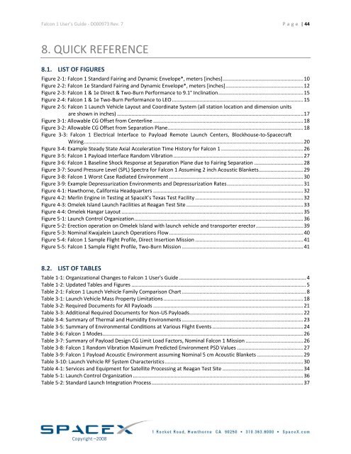
<strong>Falcon</strong> 1 User’s <strong>Guide</strong> ‐ D000973 <strong>Rev</strong>. 7 Page | 44<br />
8. QUICK REFERENCE<br />
8.1. LIST OF FIGURES<br />
Figure 2‐1: <strong>Falcon</strong> 1 St<strong>and</strong>ard Fairing <strong>and</strong> Dynamic Envelope*, meters [inches] ........................................................ 10<br />
Figure 2‐2: <strong>Falcon</strong> 1e St<strong>and</strong>ard Fairing <strong>and</strong> Dynamic Envelope*, meters [inches] ...................................................... 12<br />
Figure 2‐3: <strong>Falcon</strong> 1 & 1e Direct & Two‐Burn Performance to 9.1° Inclination ........................................................... 15<br />
Figure 2‐4: <strong>Falcon</strong> 1 & 1e Two‐Burn Performance to LEO ........................................................................................... 15<br />
Figure 2‐5: <strong>Falcon</strong> 1 Launch Vehicle Layout <strong>and</strong> Coordinate System (all station location <strong>and</strong> dimension units<br />
are shown in inches) ................................................................................................................................. 17<br />
Figure 3‐1: Allowable CG Offset from Centerline ........................................................................................................ 18<br />
Figure 3‐2: Allowable CG Offset from Separation Plane .............................................................................................. 18<br />
Figure 3‐3: <strong>Falcon</strong> 1 Electrical Interface to Payload Remote Launch Centers, Blockhouse‐to‐Spacecraft<br />
Wiring ........................................................................................................................................................ 20<br />
Figure 3‐4: Example Steady State Axial Acceleration Time History for <strong>Falcon</strong> 1 ......................................................... 26<br />
Figure 3‐5: <strong>Falcon</strong> 1 Payload Interface R<strong>and</strong>om Vibration .......................................................................................... 27<br />
Figure 3‐6: <strong>Falcon</strong> 1 Baseline Shock Response at Separation Plane due to Fairing Separation .................................. 28<br />
Figure 3‐7: Sound Pressure Level (SPL) Spectra for <strong>Falcon</strong> 1 Assuming 2 inch Acoustic Blankets ............................... 29<br />
Figure 3‐8: <strong>Falcon</strong> 1 Worst Case Radiated Environment ............................................................................................. 30<br />
Figure 3‐9: Example Depressurization Environments <strong>and</strong> Depressurization Rates ..................................................... 31<br />
Figure 4‐1: Hawthorne, California Headquarters ........................................................................................................ 32<br />
Figure 4‐2: Merlin Engine in Testing at SpaceX’s Texas Test Facility ........................................................................... 32<br />
Figure 4‐3: Omelek Isl<strong>and</strong> Launch Facilities at Reagan Test Site ................................................................................. 33<br />
Figure 4‐4: Omelek Hangar Layout .............................................................................................................................. 35<br />
Figure 5‐1: Launch Control Organization ..................................................................................................................... 36<br />
Figure 5‐2: Erection operation on Omelek Isl<strong>and</strong> with launch vehicle <strong>and</strong> transporter erector ................................. 39<br />
Figure 5‐3: Nominal Kwajalein Launch Operations Flow ............................................................................................. 40<br />
Figure 5‐4: <strong>Falcon</strong> 1 Sample Flight Profile, Direct Insertion Mission ........................................................................... 41<br />
Figure 5‐5: <strong>Falcon</strong> 1 Sample Flight Profile, Two‐Burn Mission .................................................................................... 41<br />
8.2. LIST OF TABLES<br />
Table 1‐1: Organizational Changes to <strong>Falcon</strong> 1 <strong>User's</strong> <strong>Guide</strong> ........................................................................................ 4<br />
Table 1‐2: Updated Tables <strong>and</strong> Figures ......................................................................................................................... 5<br />
Table 2‐1: <strong>Falcon</strong> 1 Launch Vehicle Family Comparison Chart ...................................................................................... 8<br />
Table 3‐1: Launch Vehicle Mass Property Limitations ................................................................................................. 18<br />
Table 3‐2: Required Documents for All Payloads ........................................................................................................ 21<br />
Table 3‐3: Additional Required Documents for Non‐US Payloads ............................................................................... 22<br />
Table 3‐4: Summary of Thermal <strong>and</strong> Humidity Environments .................................................................................... 23<br />
Table 3‐5: Summary of Environmental Conditions at Various Flight Events ............................................................... 24<br />
Table 3‐6: <strong>Falcon</strong> 1 Modes ........................................................................................................................................... 26<br />
Table 3‐7: Summary of Payload Design CG Limit Load Factors, Nominal <strong>Falcon</strong> 1 Mission ........................................ 26<br />
Table 3‐8: <strong>Falcon</strong> 1 R<strong>and</strong>om Vibration Maximum Predicted Environment PSD Values .............................................. 27<br />
Table 3‐9: <strong>Falcon</strong> 1 Payload Acoustic Environment assuming Nominal 5 cm Acoustic Blankets ................................ 29<br />
Table 3‐10: Launch Vehicle RF System Characteristics ................................................................................................ 30<br />
Table 4‐1: Services <strong>and</strong> Equipment for Satellite Processing at Reagan Test Site ........................................................ 34<br />
Table 5‐1: Launch Control Organization ...................................................................................................................... 36<br />
Table 5‐2: St<strong>and</strong>ard Launch Integration Process ......................................................................................................... 37<br />
Copyright –2008


