Manual Backflow Preventer Test Kit TK 9A - Watts waterbeveiliging
Manual Backflow Preventer Test Kit TK 9A - Watts waterbeveiliging
Manual Backflow Preventer Test Kit TK 9A - Watts waterbeveiliging

Create successful ePaper yourself
Turn your PDF publications into a flip-book with our unique Google optimized e-Paper software.
<strong>Manual</strong> <strong>Backflow</strong> <strong>Preventer</strong> <strong>Test</strong> <strong>Kit</strong> <strong>TK</strong> <strong>9A</strong><br />
2<br />
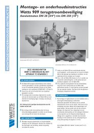
differential<br />
pressure gauge<br />
high pressure hose<br />
(yellow)<br />
shutoff valves<br />
A<br />
0<br />
0.25<br />
0.5<br />
BAR<br />
0.75<br />
1<br />
B<br />
C<br />
low<br />
pressure<br />
hose<br />
(red)<br />
(blue)<br />
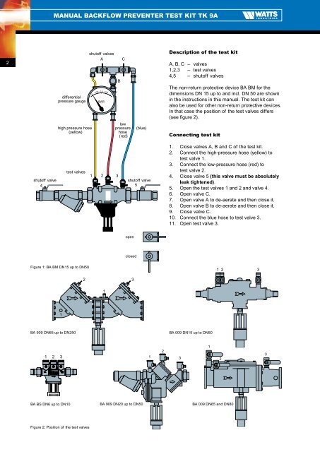
Description of the test kit<br />
A, B, C – valves<br />
1,2,3 – test valves<br />
4,5 – shutoff valves<br />
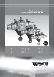
The non-return protective device BA BM for the<br />
dimensions DN 15 up to and incl. DN 50 are shown<br />
in the instructions in this manual. The test kit can<br />
also be used for other non-return protective devices.<br />
In that case the position of the test valves differs<br />
(see figure 2).<br />
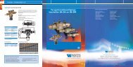
Connecting test kit<br />
shutoff valve<br />
4<br />
test valves<br />
1<br />
2 3<br />
shutoff valve<br />
5<br />
1. Close valves A, B and C of the test kit.<br />
2. Connect the high-pressure hose (yellow) to<br />
test valve 1.<br />
3. Connect the low-pressure hose (red) to<br />
test valve 2.<br />
4. Close valve 5 (this valve must be absolutely<br />
leak tightened).<br />
5. Open the test valves 1 and 2 and valve 4.<br />
6. Open valve C.<br />
7. Open valve A to de-aerate and then close it.<br />
8. Open valve B to de-aerate and then close it.<br />
9. Close valve C.<br />
10. Connect the blue hose to test valve 3.<br />
11. Open test valve 3.<br />
open<br />
closed<br />
Figure 1: BA BM DN15 up to DN50<br />
1 2 3<br />
2 3<br />
1<br />
1<br />
BA 909 DN65 up to DN250<br />
BA 009 DN15 up to DN50<br />
1 2 3 1<br />
2<br />
3<br />
1<br />
2<br />
3<br />
BA BS DN6 up to DN10<br />
BA 909 DN20 up to DN50<br />
BA 009 DN65 and DN80<br />
Figure 2: Position of the test valves