CATALOGUE OF sphEriCAL rOLLEr And spECiAL ... - R & M Bearings
CATALOGUE OF sphEriCAL rOLLEr And spECiAL ... - R & M Bearings
CATALOGUE OF sphEriCAL rOLLEr And spECiAL ... - R & M Bearings

Create successful ePaper yourself
Turn your PDF publications into a flip-book with our unique Google optimized e-Paper software.
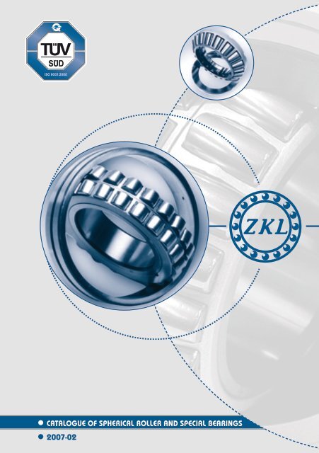
<strong>CATALOGUE</strong> <strong>OF</strong> spherical roller and special bearings<br />
2007-02
CONTENTS<br />
Double Row Spherical Roller <strong>Bearings</strong> ........................................................................................................................ 003<br />
Double Row Cylindrical Roller <strong>Bearings</strong> ...................................................................................................................... 039<br />
Spherical Roller Thrust <strong>Bearings</strong> ................................................................................................................................... 043<br />
Special <strong>Bearings</strong> ................................................................................................................................................................ 059
DOUBLE ROW SPHERICAL ROLLER BEARINGS
DOUBLE ROW SPHERICAL ROLLER BEARINGS<br />
Double row spherical roller bearings have two rows of spherical rollers with common spherical raceway in<br />
outer ring. This internal bearing design enables mutual tilting of rings. Under load the spherical roller in some<br />
designs rest by their facial surface on fixed or floating center rib, guiding the rollers. Double row spherical roller<br />
bearings are not easily separable and are being mounted as a complete unit. They can accommodate great<br />
radial and simultaneously also axial loads in both directions. Double row spherical roller bearings have either<br />
cylindrical or tapered bore and are produced with steel sheet cage (J) or with machined brass cage (M).<br />
Designation of Double Row Spherical Roller <strong>Bearings</strong><br />
Note:<br />
* Symbols of tolerance class, radial clearance and vibration level can be joined,<br />
such as P6 + C4 + C6 = P646.<br />
D O U B L E R O W S P H E R I C A L R O L L E R B E A R I N G S 0 0 3
All double row spherical roller bearings are designed and manufactured according to Czech CSN standards,<br />
which fully comply with the international standards ISO. Quality management system of the whole manufacturing<br />
process of double row spherical roller bearings is certified according to international standards series<br />
ISO 9000.<br />
Double row spherical roller bearings are utilized in many industrial branches. For their specific properties they<br />
are particularly suitable in the following installations and mechanisms:<br />
– gearboxes of trucks and heavy-duty construction, road building and mining machinery<br />
– heavy-duty paper machines<br />
– mountings of railway car axles and bogies, electric locomotives<br />
– intricate mountings of tunnelling machines and shields, screening and sorting machines<br />
– heavy engineering industry: presses, intricate turntables, heavy-duty machine tools, crushers, cranes<br />
– metallurgical industry: rolling mills, converter mountings<br />
– power industry: turbines, generators.<br />
Boundary Dimensions<br />
Boundary dimensions of double row spherical roller bearings shown in dimensional tables comply with international<br />
dimensional plan ISO. Manufacture of bearings of differing dimensions should be negotiated with the<br />
manufacturer first.<br />
Review of <strong>Bearings</strong> Execution<br />
0 0 4<br />
D O U B L E R O W S P H E R I C A L R O L L E R B E A R I N G S
Groove and Lubricating Holes on Outer Ring<br />
When double row spherical roller bearings are provided with a groove on perimeter and with three lubricating<br />
holes (W33), eventually three lubricating holes only (W20) , the lubricant can be fed straight into the bearing<br />
between two spherical roller rows. This enables to achieve better lubrication and higher operating reliability.<br />
Tolerance<br />
Double row spherical roller bearings are commonly manufactured in normal tolerance class PO. This symbol<br />
is not shown in bearing designation. Manufacture of bearings of higher tolerance class should be negotiated<br />
with the manufacturer. Limiting deviation values of dimensions and run tolerances are shown in ISO 492.<br />
Radial Clearance<br />
Currently manufactured double row spherical roller bearings are of normal radial clearance, which is not<br />
shown in bearing designation. On client’s request for special purpose arrangements these bearings may be<br />
manufactured with radial clearance C2 (lesser than normal) or with radial clearance C3, C4 or C5 (greater<br />
than normal). Clearances values are shown in the next tables.<br />
D O U B L E R O W S P H E R I C A L R O L L E R B E A R I N G S 0 0 5
0 0 6<br />
D O U B L E R O W S P H E R I C A L R O L L E R B E A R I N G S
Tapered Bore<br />
Double row spherical roller bearings are manufactured either with cylindrical or with tapered bore (K) with<br />
taper ratio 1:12. <strong>Bearings</strong> with tapered bore are mounted either straight on tapered journal or on cylindrical<br />
journal by means of adapter sleeves or withdrawal sleeves. These bearings can also be supplied with tapered<br />
bore of taper ratio 1:30 (K30).<br />
Self-Alignment<br />
Double row spherical roller bearings can be tilted off the central position, without impairing their correct function.<br />
Values of permitted tilting are shown in the table:<br />
Cages<br />
Double row spherical roller bearings are manufactured in various design executions, with pressed steel sheet<br />
cages (J) , or machined brass cages (M) .Cages can be centered by rolling elements, by inner rings or by outer<br />
ring raceway. Upon client’s request cages in other non-standard executions may also be supplied. <strong>Bearings</strong> in<br />
EJ and CJ execution can be delivered also with JTN design. This design increases limiting speed frequency<br />
by 10 %.<br />
D O U B L E R O W S P H E R I C A L R O L L E R B E A R I N G S 0 0 7
<strong>Bearings</strong> According to Special Technical Conditions<br />
<strong>Bearings</strong> can also be manufactured according to special conditions agreed upon with the buyer. Such bearings<br />
are marked by supplementary designation TPF.<br />
Connecting Surfaces Dimensions<br />
Bearing rings may bear only on facial resting surface on the shaft or on the housing but not on the rounding.<br />
Maximum radius of connected parts r a<br />
must therefore be smaller than the minimum dimension of rounding<br />
of bearing rings r smin<br />
.<br />
Operating Temperature Effect on <strong>Bearings</strong> Material<br />
All spherical roller bearings pass special heat treatment permitting their use under operating temperature up<br />
to 200 °C without inadmissible dimensional changes.<br />
Operating Temperature and Axial Load<br />
Thanks to their inner design the bearings exposed to radial load can accommodate a sizeable axial load too.<br />
In case F a<br />
/ F r<br />
> e (see bearings tables), it is recommended to shorten the re-lubrication intervals in grease<br />
lubrication. Operating temperature may be a limiting factor as far as the axial load is concerned. In such a case<br />
we recommend to contact the Technical Consultation Services department of ZKL Vyzkum a vyvoj, a.s., who is<br />
prepared to evaluate suitability of selected bearing for particular operating conditions and mounting.<br />
Axial Load Rating of <strong>Bearings</strong> Mounted on Adapter Sleeves<br />
When mounting spherical roller bearings on plain shafts by means of adapter sleeves, the magnitude of axial<br />
load accommodated by the bearing depends on friction between the shaft and sleeve. Provided the bearings<br />
are properly mounted, we may calculate the permissible axial load from this relation:<br />
F ap<br />
= 3 · B · d<br />
where<br />
F ap<br />
B<br />
d<br />
. . . maximum permissible axial load [N]<br />
. . . bearing width [mm]<br />
. . . bearing bore diameter [mm]<br />
Minimum Load<br />
Rolling bearings with point and linear contact must be exposed to certain minimum load to secure their<br />
trouble-free operation. This applies to spherical roller bearings as well and particularly for operation at high<br />
speeds, when inertial forces of spherical rollers and of cage, plus friction in lubricant may have adverse influence<br />
on rolling and may result in damage of spherical rollers and of raceways. The needed minimum load for<br />
such cases can be estimated from this relation:<br />
F rm<br />
= 0,02 · Cr<br />
where<br />
F rm<br />
Cr<br />
. . . minimum radial load [N]<br />
. . . basic dynamic load rating [N]<br />
As a rule the mass of parts accommodated by the bearing along with external acting forces exceed the required<br />
minimum load. Should it not be the case, the bearing must be loaded by a supplementary force, such<br />
as by belt tightening, by higher torque at idle run or similar.<br />
Dynamic Load<br />
Basic Dynamic Load Rating<br />
The basic dynamic load rating is a non-variable load under which the bearing reaches one million of revolutions.<br />
For radial bearings the basic radial load rating C r<br />
refers to purely radial load (for thrust bearings the basic<br />
axial load rating C a<br />
applies to purely axial load acting in bearing axis). Basic dynamic load rating magnitude<br />
depends on bearing dimension, number of rolling elements, bearing material and design. Values of basic<br />
dynamic load rating are specified in compliance with ISO 281.<br />
0 0 8<br />
D O U B L E R O W S P H E R I C A L R O L L E R B E A R I N G S
Equivalent Dynamic Load<br />
For calculation of the service life it is necessary first to convert the real acting load to equivalent load, i.e. imaginary<br />
constant load corresponding to preconditions for calculation of basic dynamic load ratings and having<br />
identical influence on bearing service life as a real acting load. Only then this load can be used for calculation of<br />
C / P relation. For correct calculation we must know most precisely the external forces acting on the bearing.<br />
Radial <strong>Bearings</strong><br />
Radial equivalent dynamic load is an imaginary value which can be determined at combined load (at simultaneous<br />
radial and axial loads) by these equations:<br />
P er<br />
= F r<br />
+ Y 1<br />
· F a<br />
P er<br />
= 0,67 · F r<br />
+ Y 2<br />
· F a<br />
for F a<br />
/ F r<br />
≤ e<br />
for F a<br />
/ F r<br />
> e<br />
where<br />
. . . radial equivalent dynamic load [N]<br />
. . . radial load [N]<br />
. . . axial load [N]<br />
e, Y 1<br />
, Y 2<br />
. . . values of e, Y 1<br />
, Y 2<br />
coefficients are shown in tabular part.<br />
P er<br />
F r<br />
F a<br />
Static Load<br />
Basic Static Load Rating<br />
When a bearing is exposed to load at standstill or at very slow rotation, at oscillation or when a bearing is<br />
exposed to impacts and forces for a period shorter than one single revolution, we cannot define permissible<br />
bearing load by dynamic fatigue of functional surfaces but by permissible permanent deformations of raceways<br />
and of rolling elements. The values of basic radial static load rating C or<br />
(and of basic axial static load rating<br />
C oa<br />
for spherical roller thrust bearings) were determined in conformity with the international standard ISO<br />
76. Basic static load rating is the load which causes total plastic deformation in the extent of 1·10 -4 of rolling element<br />
diameter in contact spot of the most loaded rolling element in central part of contact area between the<br />
rolling element and raceway. Under normal lubricating conditions this value corresponds to maximum contact<br />
load of approx. 4000 Mpa. The safety criterion regarding occurrence of extremely great plastic deformations<br />
is the safety coefficient at static load s o<br />
.<br />
s o<br />
= C ____ or<br />
P oe<br />
where<br />
C or<br />
P oe<br />
s o<br />
. . . basic radial static load rating [N]<br />
. . . equivalent static load [N]<br />
. . . static safety<br />
High value of static safety is advisable for bearings requiring easy revolving and smooth run; where lesser<br />
requirements of smooth run exist, lower s o<br />
coefficient values will do.<br />
Determination of s o<br />
coefficient values is mostly based on practice and experience.<br />
Equivalent Static Load<br />
Relation of equivalent static load with real acting load and its definition is analogous as in equivalent dynamic load.<br />
P oer<br />
= F r<br />
+ Y o<br />
F a<br />
where<br />
P oer<br />
F r<br />
F a<br />
Y o<br />
. . . radial equivalent static load [N]<br />
. . . radial load [N]<br />
. . . axial load [N]<br />
. . . value of Yo coefficient is shown in tabular part.<br />
D O U B L E R O W S P H E R I C A L R O L L E R B E A R I N G S 0 0 9
Limiting Speed Frequency<br />
Limiting Speed Frequency shown in catalogue table part is the maximum number of revolutions at which the<br />
– bearing operates with a certain safety measure faultlessly under the following operating conditions:<br />
– bearing load corresponds to service life L 10h =~ 100 000 hours<br />
– axial element of forces magnitude F a<br />
loading spherical roller radial bearing reaches 25% of radial component<br />
force F r<br />
at maximum<br />
– bearings are manufactured with normal tolerance class, with normal radial clearance<br />
– limiting speed frequency for oil lubrication is understood for oil bath lubrication.<br />
If the bearing operates at a higher load than above, it is necessary to rectify the limiting speed frequency. For<br />
instance, if the bearing load corresponds to bearing service life L 10h<br />
= 20 000 hours, the limiting speed frequency<br />
value should be reduced by 3 to 28 percent depending on bearing size (smaller bearings need minor<br />
correction); when the load corresponds to service life of L 10h<br />
= 5 000 hours, the rectification of limiting speed<br />
frequency ranges between 10 to 65 percent.<br />
Similarly the limiting speed frequency must be reduced if axial load magnitude of radial bearings exceeds 25<br />
percent of force radial element. For instance, if F a<br />
/ F r<br />
= 0.6, the limiting speed frequency has to be reduced<br />
by 10%, if F a<br />
/ F r<br />
= 2, the limiting speed frequency should be reduced by 26%.<br />
On the other hand, the catalogue limiting speed frequency may be exceeded under certain conditions. For<br />
example, limiting speed frequency of spherical roller radial bearing may be increased, provided these conditions<br />
are adhered to:<br />
– bearing load and F a<br />
values correspond to catalogue operating conditions (L 10h<br />
= 100 000 hours,<br />
relation F a<br />
/ F r<br />
does not exceed the value of 2.5)<br />
– adequately efficient oil circulation lubrication is secured<br />
– the bearing and all parts relating to it are manufactured with higher accuracy<br />
– the bearing of higher radial clearance (C3) is used.<br />
Whenever the value of limiting speed frequency of bearings, operating under other conditions than that ruling<br />
for limiting speed frequency shown in catalogue table part, needs to be determined, we recommend to consult<br />
Technical and Consulting Services department of ZKL – Vyzkum a vyvoj, a. s. for advice.<br />
Lubrication of <strong>Bearings</strong><br />
Grease Lubrication<br />
Lubrication by grease has a number of practical advantages in comparison with oil lubrication and therefore<br />
it is preferred wherever this lubrication method can be applied. As a rule mounting designs of bearings lubricated<br />
by grease are simple, costs of sealing the bearing space are lower than for oil lubrication and risk of<br />
lubricant escape is not so great compared with oil lubrication.<br />
At first mounting the inner bearing space is filled by grease fully, while the free space round the bearing is filled<br />
just to one third and not more than to its half. In order to prevent possible contamination or other degradation<br />
of lubricant in the process of mounting we recommend to lubricate the bearings only after fitting is finished,<br />
whenever possible.<br />
Grease will lose its lubricating properties after certain time. Main factors influencing grease life are:<br />
– lubricant quality<br />
– bearing size<br />
– operating speed<br />
– operating temperature<br />
– working environment<br />
0<br />
1 0<br />
D O U B L E R O W S P H E R I C A L R O L L E R B E A R I N G S
It is therefore necessary to re-lubricate the bearings regularly. The recommended re-lubrication interval length tf<br />
can be read in the following graph specifying its value in dependence to operating speed n and bearing bore<br />
diameter d. This diagram applies to these operating conditions:<br />
– bearing load does not exceed 15 percent of basic dynamic load rating<br />
– grease of standard quality is used<br />
– bearing outer ring operating temperature is 70 °C at maximum<br />
– bearing in mounted on horizontal shaft.<br />
If operating temperature exceeds 70 °C, the re-lubrication interval becomes shorter – to its half for each 15 °C<br />
exceeding 70 °C temperature. Contrary to it, at a temperature below 40 °C it is possible to lengthen the re-lubrication<br />
interval twice as much. In respect of bearings fitted on vertical shafts we recommend to reduce tf shown<br />
in diagram to its half.<br />
Lubricant quantity Q needed for bearing re-lubrication can be determined either according to the instruction of<br />
manufacturer of the equipment in which the bearing is installed, or according to the following relation:<br />
Q = 0.005 ∙ D ∙ B<br />
where<br />
Q<br />
D<br />
B<br />
. . .lubricant quantity [g]<br />
. . .outer bearing diameter [mm]<br />
. . .bearing width [mm]<br />
D O U B L E R O W S P H E R I C A L R O L L E R B E A R I N G S 0 1 1
Best method of grease application into the bearing is the use of a lubricating device – grease gun. In respect<br />
of W33 bearings the most convenient way (provided the mounting arrangement allows it) is to apply grease<br />
through outer ring holes.<br />
When a bearing operates at a rather high speed, i.e. frequent re-lubrication is needed, a risk of lubricant stacking<br />
in bearing space exists. Such lubricant should be removed after a certain time. For this purpose so called<br />
lubricant slinger being a part of mounting design usefully serves. When using lubricant slinger with new series<br />
of spherical roller bearings operating at higher speeds a rich lubrication must be applied at the operation start.<br />
One hour after new bearing start and 24 hours after again a triple grease quantity should be applied.<br />
Important note: always use the same type of grease at re-lubrication as that applied in the bearing originally.<br />
Never mix different greases unless you are sure of their compatibility. Since mixing of various greases cannot<br />
be absolutely excluded in regular practice, we may use with relatively no consequences the mixtures of:<br />
– greases with identical thickener<br />
– lithium / calcium soap based greases<br />
– calcium / bentonite based greases.<br />
Combinations of following greases are inappropriate:<br />
– sodium / lithium<br />
– sodium / calcium<br />
– sodium / aluminum<br />
– sodium / bentonite<br />
– aluminum / bentonite.<br />
When mixing such greases their structure may become altered, in addition to that acute softening of the<br />
grease may occur. Should there exist the necessity to change to another type of grease, re-lubrication must<br />
be made by a great quantity of lubricant (grease flushing) whenever the mounting design allows it. Next relubrication<br />
has to be made at a shorter time interval.<br />
Overview of grease is shown in the table:<br />
0<br />
1 2<br />
D O U B L E R O W S P H E R I C A L R O L L E R B E A R I N G S
Oil Lubrication<br />
Lubrication of bearings by oil is used mostly in following cases:<br />
– re-lubrication intervals by grease are too short<br />
– bearing operating temperature is too high and thus use of grease is unsuitable<br />
– the entire unit (such as the gearbox) is lubricated by oil.<br />
Spherical roller bearings are lubricated either by oil bath lubrication, when oil level is maintained in the height<br />
of the bearing lowest rolling element center, or by oil circulation lubrication. As a rule rolling bearings are lubricated<br />
by mineral oils of good chemical stability. Appropriate mineral oil reference viscosity υ 1<br />
is determined<br />
from the next diagram, in dependence on bearing mean diameter:<br />
d s<br />
= (D + d) / 2<br />
where<br />
d s<br />
D<br />
d<br />
. . . bearing mean diameter [mm]<br />
. . . bearing outer diameter [mm]<br />
. . . bore diameter [mm]<br />
If operating temperature t of the bearing is known or can be established, we can determine the operating viscosity<br />
υ at internationally standardized reference temperature of 40°C, needed for calculation of viscosity ratio:<br />
κ = υ / υ 1<br />
where<br />
κ<br />
υ<br />
υ 1<br />
. . . viscosity ratio<br />
. . . operating viscosity [mm2.s-1]<br />
. . . reference viscosity [mm2.s-1]<br />
If κ is smaller than 1, it is advisable to use oils with so-called EP additives to prevent caking of metallic parts<br />
in the contact point at local temperature rise). When κ value falls below 0.4, the use of oil with EP additives<br />
is inevitable.<br />
D O U B L E R O W S P H E R I C A L R O L L E R B E A R I N G S 0 1 3
Graph for Determination of Operative Viscosity<br />
0 1 4<br />
D O U B L E R O W S P H E R I C A L R O L L E R B E A R I N G S
Graph for Determination of Kinematic Viscosity<br />
Viscosity – temperature 40 °C<br />
D O U B L E R O W S P H E R I C A L R O L L E R B E A R I N G S 0 1 5
Mounting and Dismounting of Spherical Roller <strong>Bearings</strong><br />
Workplace cleanness, i.e. both cleanness of bearings and lubricant and of further components of the mounting<br />
and of mounting devices, is the principal prerequisite of correct mounting and dismounting. <strong>Bearings</strong><br />
should be removed from their protective packing not until but shortly before mounting.<br />
Mounting of <strong>Bearings</strong> with Cylindrical Bore<br />
<strong>Bearings</strong> may be mounted on journals or into housings bores either under cold or hot mounting process. It is<br />
recommended to cold mount rather smaller bearings. The force necessary for mounting is applied either by<br />
a press or by hammer strokes. We recommend the use a mechanical or hydraulic press instead of striking,<br />
wherever possible. In both cases an assembly jig should be applied on bearing ring just installed; direct strikes<br />
must not be thrown on bearing rings! The installing force must not be transferred over rolling elements. The<br />
tube-shape assembly jig should lean on the ring being mounted, eventually on both rings simultaneously.<br />
Force needed for mounting grows with the bearing size and therefore larger bearings must be hot mounted.<br />
The most frequent heating methods are<br />
– in oil bath<br />
– induction heating<br />
– in heating furnace.<br />
<strong>Bearings</strong> are heated to the temperature of maximum 100 °C. Heating the bearings by welding equipment<br />
open flame is prohibited.<br />
Mounting of <strong>Bearings</strong> with Tapered Bore<br />
<strong>Bearings</strong> with tapered bore are fitted on the shaft by adapter or withdrawal sleeves, or directly on tapered<br />
journal.<br />
Sufficiently reliable fitting of inner ring is checked at mounting by measuring of reduced bearing radial clearance<br />
(using feeler gauges), or by measurement of inner ring axial offset length on the journal or on adapter<br />
/ withdrawal sleeve. The initial position for measurement of axial offset is such position at which contact surfaces<br />
of the ring and of the shaft (or journal) seat against each other on the whole seating surface. The values<br />
needed for mounting are shown in the next table.<br />
Inner rings may be installed in following ways:<br />
– by striking the assembly sleeve<br />
– by means of KM nut and assembly spanner<br />
– by means of special hydraulic nut<br />
– by hot mounting.<br />
<strong>Bearings</strong> with tapered bore are mounted on the shaft always with an offset. The offset magnitude is measured<br />
either by reduced radial clearance of mounted bearing or by axial displacement of the inner ring on tapered<br />
journal. In respect of double row spherical roller bearings we recommend to measure the radial clearance<br />
decrease (reduction). Simple checking the axial displacement (offset) is allowed for small size bearings or<br />
in limited space conditions, anyhow this requires good experience to define the initial starting position. For<br />
measurement of radial clearance before, during and after installation the common feeler gauges are used.<br />
Clearance should be measured between outer ring raceway and unloaded spherical roller in upper part of the<br />
bearing. Prior to measuring the bearing should be turned repeatedly so that the rollers settle down to correct<br />
position. When measuring, press the spherical roller slightly to centering ring (according to design solution)<br />
between both roller rows. The measured radial clearance value must be identical for both rows of spherical<br />
rollers. Recommended values of radial clearance reduction and of axial offset for spherical roller bearings with<br />
tapered bore are shown in the next table. If this recommendation is adhered to, the offset is fully adequate<br />
(particularly for reaching the upper limit of radial clearance reduction), see table.<br />
0<br />
1 6<br />
D O U B L E R O W S P H E R I C A L R O L L E R B E A R I N G S
Recommended Values of Radial Clearance Reduction and of Inner Ring Axial Offset for Mounting of Double<br />
Row Spherical Roller <strong>Bearings</strong> with Tapered Bore of 1:12 and 1:30 Tapered Ratio<br />
D O U B L E R O W S P H E R I C A L R O L L E R B E A R I N G S 0 1 7
Dismounting of <strong>Bearings</strong><br />
<strong>Bearings</strong> with cylindrical bore are dismounted by using mechanical pullers (in case of small and medium<br />
sized bearings) or by pressure oil (medium and large bearings). As for the bearings fitted on tapered journal,<br />
mechanical pullers serve for small bearings dismounting only while medium sized and large bearings need<br />
pressure oil. Small and medium sized bearings fitted on adapter sleeve are removed by withdrawal sleeve, for<br />
medium sized and large bearings fitted on adapter sleeves special hydraulic nut should be used. Small and<br />
medium sized bearings fitted on withdrawal sleeves are dismounted by means of KM nut and mounting spanner,<br />
for large bearings special hydraulic nut should be used.<br />
0<br />
1 8<br />
D O U B L E R O W S P H E R I C A L R O L L E R B E A R I N G S
DOUBLE ROW SPHERICAL ROLLER BEARINGS<br />
d = 25 to 65 mm<br />
Dimensions<br />
d D B r s<br />
min<br />
mm<br />
Basic Load Rating<br />
Dynamic<br />
C r<br />
Static<br />
C or<br />
Limiting Speed Frequency<br />
for Lubrication<br />
by Grease<br />
by Oil<br />
Cylindrical<br />
Bore<br />
Mass<br />
kN min -1 kg<br />
Tapered<br />
Bore<br />
Cylindrical Bore<br />
Bearing Designation<br />
25 52 18 1 46 46.1 8500 11000 0.16 0.155 22205EW33J<br />
30 62 20 1 60.9 64.5 7500 9500 0.25 0.245 22206EW33J<br />
35 72 23 1.1 80.7 92 6300 8000 0.42 0.41 22207EW33J<br />
40 80 23 1.1 93.1 105 6000 7500 0.51 0.5 22208EW33J<br />
40 90 33 1.5 132 149 4100 5100 1.07 1.05 22308EW33J<br />
40 90 33 1.5 132 149 4100 5100 1.07 1.05 22308EW33MH*<br />
45 85 23 1.1 97.3 113 5300 6700 0.55 0.53 22209EW33J<br />
45 100 36 1.5 159 182 3700 4600 1.43 1.4 22309EW33J<br />
45 100 36 1.5 159 182 3700 4600 1.43 1.4 22309EW33MH*<br />
50 90 23 1.1 105 124 5000 6300 0.59 0.57 22210EW33J<br />
50 110 40 2 191 225 3300 4000 1.92 1.88 22310EW33J<br />
50 110 40 2 191 225 3300 4000 1.92 1.88 22310EW33MH*<br />
55 100 25 1.5 124 148 4500 5600 0.78 0.76 22211EW33J<br />
55 120 43 2 230 279 3000 3800 2.4 2.3 22311EW33J<br />
55 120 43 2 221 264 3000 3800 2.45 2.4 22311EW33MH*<br />
60 110 28 1.5 140 174 4000 5000 1.07 1.05 22212EW33J<br />
60 130 46 2.1 273 315 2800 3600 2.9 2.8 22312EW33J<br />
60 130 46 2.1 209 230 2800 3300 3 2.9 22312W33M*<br />
65 120 31 1.5 177 216 3800 4800 1.45 1.42 22213EW33J<br />
65 140 48 2.1 304 351 2600 3400 3.5 3.4 22313EW33J<br />
65 140 48 2.1 222 252 2700 3200 3.6 3.5 22313W33M*<br />
Notice: Deliveries of bearings marked * need to be negotiated with manufacturer<br />
0 2 0<br />
D O U B L E R O W S P H E R I C A L R O L L E R B E A R I N G S
Tapered Bore<br />
Bearing Designation<br />
Connecting Dimensions<br />
d a<br />
min<br />
D a<br />
max<br />
r a<br />
max<br />
Adapter<br />
Sleeve<br />
Withdrawal<br />
Sleeve<br />
Withdrawal<br />
Nut<br />
Calculation Coefficients<br />
e Y 1<br />
Y 2<br />
Y 0<br />
mm<br />
22205EKW33J 30 47 1 H305 AH305 KM6 0.34 2 3 2<br />
22206EKW33J 35 57 1 H306 AH306 KM7 0.31 2.1 3.2 2.1<br />
22207EKW33J 42 65 1 H307 AH307 KM8 0.31 2.2 3.3 2.1<br />
22208EKW33J 47 73 1 H308 AH308 KM9 0.27 2.5 3.7 2.4<br />
22308EKW33J 47 81 1.5 H2308 AH2308 KM9 0.36 1.8 2.6 1.8<br />
22308EKW33MH 47 81 1.5 H2308 AH2308 KM9 0.36 1.8 2.6 1.8<br />
22209EKW33J 52 78 1 H309 AH309 KM10 0.26 2.6 3.9 2.6<br />
22309EKW33J 52 91 1.5 H2309 AH2309 KM10 0.35 1.7 2.7 1.8<br />
22309EKW33MH 52 91 1.5 H2309 AH2309 KM10 0.35 1.7 2.7 1.8<br />
22210EKW33J 57 83 1.2 H310 AH310X KM11 0.24 2.8 4.2 2.8<br />
22310EKW33J 60 100 2 H2310 AH2310X KM11 0.36 1.9 2.7 1.8<br />
22310EKW33MH 60 100 2 H2310 AH2310X KM11 0.36 1.9 2.7 1.8<br />
22211EKW33J 62 91 1.5 H311 AH311X KM12 0.23 2.9 4.4 2.9<br />
22311EKW33J 65 110 2 H2311 AH2311X KM12 0.35 1.9 2.8 1.9<br />
22311EKW33MH 65 110 2 H2311 AH2311X KM12 0.35 1.9 2.7 1.8<br />
22212EKW33J 67 101 1.5 H312 AH312X KM13 0.24 2.8 4.2 2.8<br />
22312EKW33J 72 118 2 H2312 AH2312X KM13 0.35 1.9 2.9 1.9<br />
22312KW33M 72 118 2 H2312 AH2312X KM13 0.41 1.6 2.4 1.6<br />
22213EKW33J 72 111 1.5 H313 AH313 KM15 0.24 2.9 4.2 2.8<br />
22313EKW33J 76 128 2 H2313 AH2313 KM15 0.34 2 3 2<br />
22313KW33M 76 128 2 H2313 AH2313 KM15 0.38 1.8 2.5 1.7<br />
D O U B L E R O W S P H E R I C A L R O L L E R B E A R I N G S 0 2 1
DOUBLE ROW SPHERICAL ROLLER BEARINGS<br />
d = 70 to 90 mm<br />
Dimensions<br />
d D B r s<br />
min<br />
mm<br />
Basic Load Rating<br />
Dynamic<br />
C r<br />
Static<br />
C or<br />
Limiting Speed Frequency<br />
for Lubrication<br />
by Grease<br />
by Oil<br />
Cylindrical<br />
Bore<br />
Mass<br />
kN min -1 kg<br />
Tapered<br />
Bore<br />
Cylindrical Bore<br />
Bearing Designation<br />
70 125 31 1.5 189 239 3600 4500 1.61 1.57 22214EW33J<br />
70 150 51 2.1 344 402 2400 3100 4.2 4.1 22314EW33J<br />
70 150 51 2.1 289 330 2400 3000 4.3 4.2 22314W33M*<br />
75 130 31 1.5 196 255 3400 4300 1.7 1.66 22215EW33J<br />
75 160 55 2.1 396 489 2300 3000 5.3 5.2 22315EW33J<br />
75 160 55 2.1 295 354 2200 2800 5.4 5.2 22315W33M*<br />
80 140 33 2 224 295 3200 4000 2.11 2.07 22216EW33J<br />
80 140 33 2 154 197 2400 3000 2.2 2.1 22216W33M*<br />
80 170 58 2.1 443 551 2200 2800 6.3 6.1 22316EW33J<br />
80 170 58 2.1 349 411 2200 2800 6.3 6.2 22316W33M*<br />
85 150 36 2 260 337 3000 3800 2.61 2.6 22217EW33J<br />
85 150 36 2 171 214 2200 2800 2.8 2.7 22217W33M*<br />
85 180 60 3 482 603 2000 2600 7.2 7 22317EW33J<br />
85 180 60 3 377 447 2000 2500 7.4 7.2 22317W33M*<br />
90 160 40 2 308 406 2600 3400 3.4 3.3 22218EW33J<br />
90 160 40 2 209 265 2000 2500 3.6 3.4 22218W33M*<br />
90 160 52,4 2 370 522 1900 2600 4.52 4.4 23218CW33J<br />
90 160 52.4 2 303 412 1900 2400 4.7 4.57 23218W33M*<br />
90 190 64 3 536 673 1900 2400 8.5 8.3 22318EW33J<br />
90 190 64 3 437 522 1900 2400 8.8 8.6 22318W33M*<br />
Notice: Deliveries of bearings marked * need to be negotiated with manufacturer<br />
0 2 2<br />
D O U B L E R O W S P H E R I C A L R O L L E R B E A R I N G S
Tapered Bore<br />
Bearing Designation<br />
Connecting Dimensions<br />
d a<br />
min<br />
D a<br />
max<br />
r a<br />
max<br />
Adapter<br />
Sleeve<br />
Withdrawal<br />
Sleeve<br />
Withdrawal<br />
Nut<br />
Calculation Coefficients<br />
e Y 1<br />
Y 2<br />
Y 0<br />
mm<br />
22214EKW33J 77 116 1.5 H314 AH314 KM16 0.23 2.9 4.2 2.8<br />
22314EKW33J 81 138 2 H2314 AH2314X KM16 0.34 2 3 2<br />
22314KW33M 81 138 2 H2314 AH2314X KM16 0.37 1.8 2.6 1.7<br />
22215EKW33J 82 121 1.5 H315 AH315 KM17 0.22 3.1 4.5 2.9<br />
22315EKW33J 86 148 2 H2315 AH2315X KM17 0.33 2 3 2<br />
22315KW33M 86 148 2 H2315 AH2315X KM17 0.38 1.8 2.5 1.7<br />
22216EKW33J 90 130 2 H316 AH316 KM18 0.22 3.1 4.5 3<br />
22216KW33M 90 130 2 H316 AH316 KM18 0.26 2.6 3.8 2.5<br />
22316EKW33J 91 158 2 H2316 AH2316X KM18 0.33 2 3 2<br />
22316KW33M 91 158 2 H2316 AH2316X KM18 0.36 1.8 2.7 1.8<br />
22217EKW33J 95 140 2 H317 AH317X KM19 0.22 3 4.4 2.9<br />
22217KW33M 95 140 2.5 H317 AH317X KM19 0.26 2.6 3.7 2.5<br />
22317EKW33J 98 166 2.5 H2317 AH2317X KM19 0.32 2.1 3.1 2<br />
22317KW33M 98 166 2.5 H2317 AH2317X KM19 0.36 1.9 2.7 1.8<br />
22218EKW33J 100 150 2 H318 AH318X KM20 0.23 2.9 4.2 2.8<br />
22218KW33M 100 150 2 H318 AH318X KM20 0.26 2.6 3.7 2.4<br />
23218CKW33J 100 150 2 H2318 AH3218X KM20 0.31 2.2 3.3 2.2<br />
23218KW33M 100 150 2 H2318 AH3218X KM20 0.33 2 3 1.9<br />
22318EKW33J 104 176 2.5 H2318 AH2318X KM20 0.33 2.1 3.1 2<br />
22318KW33M 104 176 2.5 H2318 AH2318X KM20 0.37 1.8 2.6 1.7<br />
D O U B L E R O W S P H E R I C A L R O L L E R B E A R I N G S 0 2 3
DOUBLE ROW SPHERICAL ROLLER BEARINGS<br />
d = 95 to 110 mm<br />
Dimensions<br />
d D B r s<br />
min<br />
mm<br />
Basic Load Rating<br />
Dynamic<br />
C r<br />
Static<br />
C or<br />
Limiting Speed Frequency<br />
for Lubrication<br />
by Grease<br />
by Oil<br />
Cylindrical<br />
Bore<br />
Mass<br />
kN min -1 kg<br />
Tapered<br />
Bore<br />
Cylindrical Bore<br />
Bearing Designation<br />
95 170 43 2.1 346 464 2400 3200 4.17 4.1 22219EW33J<br />
95 170 43 2.1 259 329 2000 2500 4.4 4.3 22219W33M*<br />
95 200 67 3 587 744 1800 2300 9.8 9.6 22319EW33J<br />
95 200 67 3 473 566 1800 2200 10.3 10.1 22319W33M*<br />
100 180 46 2.1 379 510 2200 3000 5 4.9 22220EW33J<br />
100 180 46 2.1 290 375 1900 2400 5.3 5.2 22220W33M*<br />
100 180 60.3 2.1 465 667 1700 2200 6.67 6.49 23220CW33J<br />
100 180 60.3 2.1 390 532 1700 2000 6.9 6.7 23220W33M*<br />
100 215 73 3 682 842 1700 2200 12.3 12.1 22320EW33J<br />
100 215 73 3 563 686 1700 2000 13 12.7 22320W33M*<br />
110 170 60 2 402 717 1800 2200 6 5.8 24022CW33J<br />
110 180 56 2 374 585 1900 2600 6 5.32 23122CW33J<br />
110 180 56 2 354 541 1700 2000 6 5.8 23122W33M*<br />
110 180 69 2 501 849 1000 1400 6.9 6.7 24122CW33J<br />
110 200 53 2.1 488 653 2000 2800 7.2 6.94 22222EW33J<br />
110 200 53 2.1 365 474 1700 2000 7.5 7.4 22222W33M*<br />
110 200 69.8 2.1 586 867 1600 2000 9.65 9.38 23222CW33J<br />
110 200 69.8 2.1 502 706 1500 1800 9.9 9.62 23222W33M*<br />
110 240 80 3 805 1000 1500 1900 17.2 16.8 22322EW33J<br />
110 240 80 3 662 801 1500 1800 18.2 17.9 22322W33M*<br />
Notice: Deliveries of bearings marked * need to be negotiated with manufacturer<br />
0 2 4<br />
D O U B L E R O W S P H E R I C A L R O L L E R B E A R I N G S
Tapered Bore<br />
Bearing Designation<br />
Connecting Dimensions<br />
d a<br />
min<br />
D a<br />
max<br />
r a<br />
max<br />
Adapter<br />
Sleeve<br />
Withdrawal<br />
Sleeve<br />
Withdrawal<br />
Nut<br />
Calculation Coefficients<br />
e Y 1<br />
Y 2<br />
Y 0<br />
mm<br />
22219EKW33J 107 158 2 H319 AH319X KM21 0.23 2.9 4.2 2.7<br />
22219KW33M 107 158 2 H319 AH319X KM21 0.26 2.5 3.6 2.4<br />
22319EKW33J 109 186 2.5 H2319 AH2319 KM21 0.33 2.1 3.1 2<br />
22319KW33M 109 186 2.5 H2319 AH2319 KM21 0.37 1.8 2.6 1.7<br />
22220EKW33J 112 168 2 H320 AH320X KM22 0.24 2.9 4.1 2.7<br />
22220KW33M 112 168 2 H320 AH320X KM22 0.27 2.5 3.6 2.4<br />
23220CKW33J 112 168 2 H2320 AH3220X KM22 0.31 2.2 3.2 2.1<br />
23220KW33M 112 168 2 H2320 AH3220X KM22 0.34 2 2.8 1.9<br />
22320EKW33J 114 201 2.5 H 2320 AH 2320X KM 22 0.33 2.0 3.0 2.0<br />
22320KW33M 113 201 2.5 H2320 AH2320X KM22 0.37 1.8 2.6 1.7<br />
24022CK30W33J 120 170 2 -- -- -- 0.32 2.1 3.2 2.1<br />
23122CKW33J 120 170 2 H3122 AH3122X KM24 0.3 2.3 3.4 2.2<br />
23122KW33M 120 170 2 H3122 AH3122X KM24 0.31 2.2 3.1 2.1<br />
24122CK30W33J 120 170 2 -- AH24122 KM23 0.35 1.9 2.8 1.9<br />
22222EKW33J 122 188 2 H3222 AH3120X KM24 0.25 2.7 4 2.6<br />
22222KW33M 122 188 2 H3222 AH3120X KM24 0.27 2.4 3.5 2.3<br />
23222CKW33J 122 188 2 H2322 AH3222X KM25 0.33 2.1 3.1 2<br />
23222KW33M 122 188 2 H2322 AH3222X KM25 0.36 1.9 2.7 1.8<br />
22322EKW33j 124 226 2.5 H2322 AH2322X KM25 0.33 2.1 3.1 2<br />
22322KW33M 124 226 2.5 H2322 AH2322X KM25 0.36 1.8 2.6 1.7<br />
D O U B L E R O W S P H E R I C A L R O L L E R B E A R I N G S 0 2 5
DOUBLE ROW SPHERICAL ROLLER BEARINGS<br />
d = 120 to 140 mm<br />
Dimensions<br />
d D B r s<br />
min<br />
mm<br />
Basic Load Rating<br />
Dynamic<br />
C r<br />
Static<br />
C or<br />
Limiting Speed Frequency<br />
for Lubrication<br />
by Grease<br />
by Oil<br />
Cylindrical<br />
Bore<br />
Mass<br />
kN min -1 kg<br />
Tapered<br />
Bore<br />
Cylindrical Bore<br />
Bearing Designation<br />
120 180 46 2 346 572 2000 2800 4.1 3.97 23024CW33J<br />
120 180 46 2 287 467 1600 1900 4.3 4.2 23024W33M*<br />
120 180 60 2 413 770 1600 2000 5.5 5.4 24024CW33J<br />
120 200 62 2 430 648 1500 1800 8.2 8 23124W33M<br />
120 200 80 2 639 1080 950 1300 10.2 10.0 24124CW33J<br />
120 215 58 2.1 553 775 1900 2600 9 8.8 22224EW33J<br />
120 215 58 2.1 439 580 1600 1900 9.4 9.2 22224W33M*<br />
120 215 76 2.1 678 1020 1500 1900 11.8 11.5 23224CW33J<br />
120 215 76 2.1 564 803 1400 1700 12.3 11.9 23224W33M*<br />
120 260 86 3 938 1180 1400 1800 21.5 21.1 22324EW33J<br />
120 260 86 3 782 962 1400 1700 22.1 21.6 22324W33M*<br />
130 200 52 2 444 711 1900 2600 5.94 5.76 23026CW33J<br />
130 200 52 2 367 579 1500 1800 6.3 6.12 23026W33M*<br />
130 200 69 2 539 978 1500 1900 8 7.9 24026CW33J<br />
130 210 64 2 474 752 1400 1700 9.1 8.82 23126W33M<br />
130 210 80 2 657 1160 900 1200 10.9 10.7 24126CW33J<br />
130 230 64 3 641 948 1800 2400 11.2 11 22226EW33J<br />
130 230 64 3 525 726 1500 1800 11.8 11.7 22226W33M*<br />
130 230 80 3 753 1180 1300 1700 13.9 13.5 23226CW33J<br />
130 230 80 3 636 948 1300 1600 15 14.4 23226W33M*<br />
130 280 93 4 1090 1380 1500 1900 26.8 26.2 22326EW33J<br />
130 280 93 4 904 1130 1300 1600 28.6 28 22326W33M*<br />
140 210 53 2 463 781 1800 2400 6.45 6.25 23028CW33J<br />
140 210 53 2 380 633 1400 1700 6.87 6.66 23028W33M*<br />
140 210 69 2 549 1040 1400 1800 8.6 8.4 24028CW33J<br />
140 225 68 2.1 540 865 1300 1600 10.8 10.5 23128W33M<br />
140 225 85 2.1 740 1330 850 1100 13.2 13.0 24128CW33J<br />
140 250 68 3 747 1080 1700 2200 14.1 13.8 22228EW33J<br />
Notice: Deliveries of bearings marked * need to be negotiated with manufacturer<br />
0 2 6<br />
D O U B L E R O W S P H E R I C A L R O L L E R B E A R I N G S
Tapered Bore<br />
Bearing Designation<br />
Connecting Dimensions<br />
d a<br />
min<br />
D a<br />
max<br />
r a<br />
max<br />
Adapter<br />
Sleeve<br />
Withdrawal<br />
Sleeve<br />
Withdrawal<br />
Nut<br />
Calculation Coefficients<br />
e Y 1<br />
Y 2<br />
Y 0<br />
mm<br />
23024CKW33J 128 171 2 H3024 AH3024X KM26 0.23 3 4.5 2.9<br />
23024KW33M 128 171 2 H3024 AH3024X KM26 0.24 2.7 3.9 2.6<br />
24024CK30W33J 128 171 2 -- AH24024 KM25 0.3 2.3 3.4 2.2<br />
23124KW33M 130 190 2 H3124 AH3124X KM26 0.31 2.1 3.1 2<br />
24124CK30W33J 131 189 2 - AH 24124 KM 26 0.37 1.8 2.7 1.8<br />
22224EKW33J 132 203 2 H3124 AH3124X KM26 0.25 2.7 3.9 2.5<br />
22224KW33M 132 203 2 H3124 AH3124X KM26 0.28 2.4 3.4 2.3<br />
23224CKW33J 132 203 2 H2324 AH3224X KM27 0.33 2 3 2<br />
23224KW33M 132 203 2 H2324 AH3224X KM27 0.36 1.9 2.7 1.8<br />
22324EKW33J 132 203 2.5 H2324 AH2324X KM27 0.33 2.1 3.1 2<br />
22324KW33M 134 246 2.5 H2324 AH2324X KM27 0.36 1.9 2.7 1.8<br />
23026CKW33J 138 191 2 H3026 AH3026X KM28 0.23 2.9 4.3 2.9<br />
23026KW33M 138 191 2 H3026 AH3026X KM28 0.26 2.6 3.8 2.5<br />
24026CK30W33J 138 191 2 -- AH24026 KM27 0.31 2.2 3.2 2.1<br />
23126KW33M 140 200 2 H3126 AH3126X KM28 0.3 2.2 3.2 2.1<br />
24126CK30W33J 141 199 2 - AH 24126 KM 28 0.35 1.9 2.9 1.9<br />
22226EKW33J 144 216 2.5 H3126 AH3126X KM28 0.26 2.6 3.8 2.5<br />
22226KW33M 144 216 2.5 H3126 AH3126X KM28 0.29 2.3 3.3 2.2<br />
23226CKW33J 144 216 2.5 H2326 AH3226X KM29 0.33 2.1 3.1 2<br />
23226KW33M 144 216 2.5 H2326 AH3226X KM29 0.35 1.9 2.7 1.8<br />
22326EKW33J 148 262 3 H2326 AH2326X KM29 0.33 2.1 3.1 2<br />
22326KW33M 148 262 3 H2326 AH2326X KM29 0.36 1.8 2.7 1.8<br />
23028CKW33J 148 200 2 H3028 AH3028X KM30 0.22 3 4.5 3<br />
23028KW33M 148 200 2 H3028 AH3028X KM30 0.24 2.7 3.9 2.6<br />
24028CK30W33J 148 200 2 -- AH24028 KM29 0.29 2.3 3.4 2.3<br />
23128KW33M 152 213 2 H3128 AH3128X KM30 0.3 2.2 3.2 2.1<br />
24128CK30W33J 152 213 2 - AH 24128 KM 30 0.35 1.9 2.9 1.9<br />
22228EKW33J 154 236 2.5 H3128 AH3128X KM30 0.25 2.7 3.9 2.5<br />
D O U B L E R O W S P H E R I C A L R O L L E R B E A R I N G S 0 2 7
DOUBLE ROW SPHERICAL ROLLER BEARINGS<br />
d = 140 to 170 mm<br />
Dimensions<br />
d D B r s<br />
min<br />
mm<br />
Basic Load Rating<br />
Dynamic<br />
C r<br />
Static<br />
C or<br />
Limiting Speed Frequency<br />
for Lubrication<br />
by Grease<br />
by Oil<br />
Cylindrical<br />
Bore<br />
Mass<br />
kN min -1 kg<br />
Tapered<br />
Bore<br />
Cylindrical Bore<br />
Bearing Designation<br />
140 250 68 3 605 822 1400 1700 15 14.6 22228W33M*<br />
140 250 88 3 815 1320 1200 1600 18.6 18 23228CW33M<br />
140 300 102 4 993 1270 1200 1500 35.6 34.8 22328W33M<br />
150 225 56 2.1 517 881 1700 2200 7.86 7.62 23030CW33J<br />
150 225 56 2.1 419 697 1300 1600 8.25 8.01 23030W33M*<br />
150 225 75 2.1 635 1220 1300 1700 10.7 10.5 24030CW33J<br />
150 250 80 2.1 711 1130 1200 1500 16.6 16.1 23130W33M<br />
150 250 100 2.1 968 1690 800 1000 19.9 19.6 24130CW33J<br />
150 270 73 3 863 1260 1600 2000 17.9 17.5 22230EW33J<br />
150 270 73 3 668 920 1300 1600 18.6 18.2 22230W33M*<br />
150 270 96 3 874 1300 1100 1400 24.6 23.9 23230W33M<br />
150 320 108 4 1100 1480 1100 1400 42,5 42,3 22330W33M<br />
160 240 60 2.1 496 848 1200 1500 10.3 10 23032W33M<br />
160 240 60 2.1 587 1010 1700 2200 9.4 9.1 23032CW33J<br />
160 240 80 2.1 719 1400 1100 1500 12.9 12.7 24032CW33J<br />
160 270 86 2.1 784 1240 1100 1400 21.3 20.7 23132W33M<br />
160 270 109 2.1 1120 1980 700 900 25.7 25.3 24132CW33J<br />
160 290 80 3 978 1440 1500 1900 22.7 22.2 22232EW33J<br />
160 290 80 3 978 1442 1650 2090 22.7 22.2 22232EW33JTN<br />
160 290 80 3 814 1140 1200 1500 24.4 23.9 22232W33M*<br />
160 290 104 3 1140 1860 1200 1600 31 30.14 23232CW33M*<br />
160 340 114 4 1250 1680 1000 1300 51.9 50.8 22332W33M<br />
170 260 67 2.1 618 1050 1100 1400 13.8 13.4 23034W33M<br />
170 260 90 2.1 875 1660 1000 1400 17.4 17.2 24034CW33J<br />
170 280 88 2.1 826 1350 1000 1300 22.8 22.2 23134W33M<br />
170 280 109 2.1 1150 2090 670 850 27.0 26.6 24134CW33J<br />
170 310 86 2.4 921 1310 1100 1400 30 29.4 22234W33M<br />
170 310 110 4 1280 1880 1100 1400 37.7 36.4 23234CW33M<br />
170 360 120 4 1400 1970 940 1200 59.2 58.2 22334W33M<br />
Notice: Deliveries of bearings marked * need to be negotiated with manufacturer<br />
0 2 8<br />
D O U B L E R O W S P H E R I C A L R O L L E R B E A R I N G S
Tapered Bore<br />
Bearing Designation<br />
Connecting Dimensions<br />
d a<br />
min<br />
D a<br />
max<br />
r a<br />
max<br />
Adapter<br />
Sleeve<br />
Withdrawal<br />
Sleeve<br />
Withdrawal<br />
Nut<br />
Calculation Coefficients<br />
e Y 1<br />
Y 2<br />
Y 0<br />
mm<br />
22228KW33M 154 236 2.5 H3128 AH3128X KM30 0.28 2.4 3.4 2.2<br />
23228CKW33M 154 236 2.5 H2328 AH3228X KM31 0.33 2 3 2<br />
22328KW33M 158 282 3 H2328 AH2328X KM31 0.38 1.8 2.5 1.7<br />
23030CKW33J 159 213 2 H3030 AH3030X KM32 0.22 3.1 4.6 3<br />
23030KW33M 159 213 2 H3030 AH3030X KM32 0.24 2.7 3.9 2.6<br />
24030CK30W33J 159 213 2 -- AH24030 KM31 0.3 2.3 3.4 2.2<br />
23130KW33M 162 238 2 H3130 AH3130X KM33 0.32 2.1 3 2<br />
24130CK30W33J 162 238 2 - AH 24130 KM 32 0.37 1.8 2.7 1.8<br />
22230EKW33J 164 256 2.5 H3130 AH3130X KM33 0.25 2.7 3.9 2.5<br />
22230KW33M 164 256 2.5 H3130 AH3130X KM33 0.28 2.3 3.4 2.2<br />
23230KW33M 164 256 2.5 H2330 AH3230X KM33 0.36 1.8 2.7 1.8<br />
22330KW33M 168 302 3 H2330 AH2330X KM33 0.38 1.8 2.6 1.7<br />
23032KW33M 169 228 2 H3032 AH3032 KM34 0.24 2.8 4 2.6<br />
23032CKW33J 171 229 2 H3032 AH3032 KM34 0.22 3.1 4.6 3<br />
24032CK30W33J 171 229 2 - AH 24032 KM 34 0.30 2.3 3.4 2.2<br />
23132KW33M 172 258 2 H3132 AH3132 KM36 0.32 2.1 3 2<br />
24132CK30W33J 172 258 2 - AH 24132 KM 34 0.38 1.8 2.7 1.8<br />
22232EKW33J 174 276 2.5 H3132 AH3132 KM36 0.26 2.6 3.8 2.5<br />
22232EKW33JTN 174 276 2.5 H3132 AH3132 KM36 0.26 2.6 3.8 2.5<br />
22232KW33M 174 276 2.5 H3132 AH3132 KM36 0.29 2.3 3.3 2.2<br />
23232CKW33M 174 276 2.5 H2332 AH3232 KM36 0.36 1.9 2.8 1.8<br />
22332KW33M 178 322 3 H2332 AH2332 KM36 0.37 1.8 2.6 1.7<br />
23034KW33M 179 248 2 H3034 AH3034 KM36 0.25 2.7 3.9 2.6<br />
24034CK30W33J 181 249 2 - AH 24034 KM 36 0.31 2.2 3.2 2.1<br />
23134KW33M 182 268 2 H3134 AH3134 KM38 0.31 2.1 3.1 2<br />
24134CK30W33J 182 268 2 - AH 24134 KM 36 0.36 1.9 2.8 1.8<br />
22234KW33M 188 293 3 H3134 AH3134 KM38 0.29 2.3 3.3 2.1<br />
23234CKW33M 188 293 3 H2334 AH3234 KM38 0.36 1.9 2.8 1.8<br />
22334KW33M 188 342 3 H2334 AH2334 KM38 0.37 1.8 2.6 1.7<br />
D O U B L E R O W S P H E R I C A L R O L L E R B E A R I N G S 0 2 9
DOUBLE ROW SPHERICAL ROLLER BEARINGS<br />
d = 180 to 220 mm<br />
Dimensions<br />
d D B r s<br />
min<br />
mm<br />
Basic Load Rating<br />
Dynamic<br />
C r<br />
Static<br />
C or<br />
Limiting Speed Frequency<br />
for Lubrication<br />
by Grease<br />
by Oil<br />
Cylindrical<br />
Bore<br />
Mass<br />
kN min -1 kg<br />
Tapered<br />
Bore<br />
Cylindrical Bore<br />
Bearing Designation<br />
180 280 74 2.1 725 1230 1000 1300 17.6 17.1 23036W33M<br />
180 280 100 2.1 1050 1980 950 1300 22.9 22.6 24036CW33J<br />
180 300 96 3 957 1540 940 1200 28.9 28 23136W33M<br />
180 300 118 3 1250 2400 700 850 32.9 32.4 24136CW33J<br />
180 320 86 4 943 1380 1000 1300 31.5 30.8 22236W33M<br />
180 320 112 4 1360 2110 1000 1300 39.8 38.6 23236CW33M<br />
180 380 126 4 1540 2130 890 1100 73.2 71.7 22336W33M<br />
190 290 75 2.1 759 1310 940 1200 18.8 18.3 23038W33M<br />
190 320 104 3 1130 1840 890 1100 36.1 35 23138W33M<br />
190 340 92 4 1040 1550 940 1200 38.4 37.7 22238W33M<br />
190 340 120 4 1550 2420 1000 1260 47.65 47.1 23238CW33M<br />
190 400 132 5 1920 2710 840 1000 84.1 82.9 22338CW33M<br />
200 310 82 2.1 880 1800 890 1100 23.8 23.4 23040CW33M<br />
200 310 109 2.1 1250 2370 900 1200 30.8 30.3 24040EW33MH<br />
200 340 112 3 1240 2010 840 1000 44 42.7 23140W33M<br />
200 340 140 3 1730 3160 560 700 53.4 52.6 24140EW33MH<br />
200 360 98 4 1164 1760 890 1100 46 45.1 22240W33M<br />
200 360 128 4 1710 2760 940 1200 58.6 56.7 23240CW33M<br />
200 420 138 5 1820 2650 790 940 99 97 22340W33M<br />
220 340 90 3 1020 2120 790 940 26.6 25.7 23044CW33M<br />
220 340 118 3 1480 2830 850 1100 39.7 39 24044EW33MH<br />
220 370 120 4 1480 2470 750 890 56.8 55.2 23144W33M<br />
220 370 150 4 1990 3690 500 630 67.1 66.1 24144EW33MH<br />
220 400 108 4 1380 2080 790 940 63 61 22244W33M<br />
220 400 144 4 2040 3750 710 840 83 79 23244CW33M<br />
220 460 145 5 2110 3130 750 890 125 122 22344W33M<br />
0 3 0<br />
D O U B L E R O W S P H E R I C A L R O L L E R B E A R I N G S
Tapered Bore<br />
Bearing Designation<br />
Connecting Dimensions<br />
d a<br />
min<br />
D a<br />
max<br />
r a<br />
max<br />
Adapter<br />
Sleeve<br />
Withdrawal<br />
Sleeve<br />
Withdrawal<br />
Nut<br />
Calculation Coefficients<br />
e Y 1<br />
Y 2<br />
Y 0<br />
mm<br />
23036KW33M 189 268 2 H3036 AH3036 KM38 0.26 2.6 3.7 2.5<br />
24036CK30W33J 191 269 2 - AH24036 KM38 0.32 2.1 3.1 2.0<br />
23136KW33M 194 286 2.5 H3136 AH3136 KM40 0.32 2.1 3 2<br />
24136CK30W33J 194 286 2.5 - AH24136 KM38 0.37 1.8 2.7 1.8<br />
22236KW33M 198 302 3 H3136 AH2236 KM40 0.28 2.4 3.4 2.3<br />
23236CKW33M 198 302 3 H2336 AH3236 KM40 0.36 1.9 2.8 1.9<br />
22336KW33M 198 362 3 H2336 AH2336 KM40 0.37 1.8 2.6 1.7<br />
23038KW33M 202 278 2 H3038 AH3038 HML41T 0.25 2.7 3.8 2.5<br />
23138KW33M 204 306 2.5 H3138 AH3138 HM42T 0.32 2.1 3 2<br />
22238KW33M 208 322 3 H3138 AH2238 HM42T 0.29 2.3 3.4 2.2<br />
23238CKW33M 208 322 3 H2338 AH3238 HM42T 0.36 1.9 2.8 1.9<br />
22338CKW33M 212 378 4 H2338 AH2338 HM42T 0.36 1.9 2.8 1.9<br />
23040CKW33M 212 298 2 H3040 AH3040 HML43T 0.25 2.7 4 2.7<br />
24040EK30W33MH 212 298 2 AOH24040 HM42 0.32 2.1 3.1 2.1<br />
23140KW33M 214 326 2.5 H3140 AH3140 HM44T 0.33 2 2.9 1.9<br />
24140EK30W33MH 214 326 2.5 AOH24140 HM42 0.39 1.9 2.6 1.7<br />
22240KW33M 218 342 3 H3140 AH2240 HM44T 0.29 2.3 3.3 2.2<br />
23240CKW33M 218 342 3 H2340 AH3240 HM44T 0.36 1.9 2.8 1.8<br />
22340KW33M 222 398 4 H2340 AH2340 HM44T 0.36 1.9 2.7 1.8<br />
23044CKW33M 234 326 2.5 H3044 AH3044 HML47T 0.25 2.7 4 2.7<br />
24044EK30W33MH 234 326 2.5 AOH24044 HM46 0.32 2.3 3.1 2.1<br />
23144KW33M 238 352 3 H3144 AH3144 HM48T 0.32 2 3 2<br />
24144EK30W33MH 238 352 3 AOH24144 HM46 0.38 1.8 2.6 1.7<br />
22244KW33M 238 382 3 H3144 AH2244 HM48T 0.28 2.4 3.4 2.2<br />
23244CKW33M 238 382 3 H2344 AH2344 HM48T 0.37 1.9 2.6 1.7<br />
22344KW33M 242 438 4 H2344 AH2344 HM48T 0.35 1.9 2.8 1.8<br />
D O U B L E R O W S P H E R I C A L R O L L E R B E A R I N G S 0 3 1
DOUBLE ROW SPHERICAL ROLLER BEARINGS<br />
d = 240 to 320 mm<br />
Dimensions<br />
d D B r s<br />
min<br />
mm<br />
Basic Load Rating<br />
Dynamic<br />
C r<br />
Static<br />
C or<br />
Limiting Speed Frequency<br />
for Lubrication<br />
by Grease<br />
by Oil<br />
Cylindrical<br />
Bore<br />
Mass<br />
kN min -1 kg<br />
Tapered<br />
Bore<br />
Cylindrical Bore<br />
Bearing Designation<br />
240 360 92 3 1080 2320 750 890 34.9 33.8 23048CW33M<br />
240 400 128 4 1690 2860 710 840 68.7 66.7 23148W33M<br />
240 400 160 4 2280 4260 480 600 82.5 81.3 24148EW33MH<br />
240 440 120 4 1660 2560 750 890 85 83.2 22248W33M<br />
240 440 160 4 2530 4300 670 850 113 110 23248CW33M<br />
240 500 155 5 2440 3690 670 790 159 156 22348W33M<br />
260 400 104 4 1460 2700 670 790 46.8 45.3 23052CW33M<br />
260 440 144 4 2240 3720 670 790 90.5 87.8 23152CW33M<br />
260 440 180 4 2790 5320 430 530 115 113 24152EW33MH<br />
260 480 130 5 1940 3030 670 790 111 109 22252W33M<br />
260 480 174 5 2700 4430 600 710 147 142 23252W33M<br />
260 540 165 6 2760 4220 600 710 196 192 22352W33M<br />
280 420 106 4 1440 2690 630 750 54.5 52.9 23056W33M<br />
280 460 146 5 2180 3900 600 710 102.8 99 23156W33M<br />
280 460 180 5 2880 5360 400 500 121 119 24156EW33MH<br />
280 500 130 5 2010 3200 630 750 119 116 22256W33M<br />
280 500 176 5 2850 4770 560 670 157 152 23256W33M<br />
280 580 175 6 3300 5600 600 750 232 227 22356CW33M<br />
300 460 118 4 1780 3240 560 670 75.8 73.6 23060W33M<br />
300 500 160 5 2560 4490 530 630 133.6 129.5 23160W33M<br />
300 500 200 5 3420 6790 360 450 163 160 24160EW33MH<br />
300 540 140 5 2350 3810 560 670 150 147 22260W33M<br />
300 540 192 5 3350 5570 500 600 200 195 23260W33M<br />
320 480 121 4 1890 3510 530 630 81.2 78.8 23064W33M<br />
320 540 176 5 3020 5390 500 600 175.3 170.1 23164W33M<br />
320 540 218 5 4020 7870 340 430 208 205 24164EW33MH<br />
320 580 150 5 2700 4430 530 630 187 181 22264W33M<br />
320 580 208 5 3880 6520 450 530 253 246 23264W33M<br />
0 3 2<br />
D O U B L E R O W S P H E R I C A L R O L L E R B E A R I N G S
Tapered Bore<br />
Bearing Designation<br />
Connecting Dimensions<br />
d a<br />
min<br />
D a<br />
max<br />
r a<br />
max<br />
Adapter<br />
Sleeve<br />
Withdrawal<br />
Sleeve<br />
Withdrawal<br />
Nut<br />
Calculation Coefficients<br />
e Y 1<br />
Y 2<br />
Y 0<br />
mm<br />
23048CKW33M 254 346 2.5 H3048 AH3048 HML52T 0.24 2.8 4.2 2.8<br />
23148KW33M 258 382 3 H3148 AH3148 HM52T 0.32 2.1 3 2<br />
24148EK30W33MH 258 422 3 AOH24148 HM50 0.38 1.8 2.7 1.8<br />
22248KW33M 258 422 3 H3148 AH2248 HM52T 0.29 2.3 3.3 2.2<br />
23248CKW33M 258 422 3 H2348 AH2348 HM52T 0.35 1.9 2.9 1.8<br />
22348KW33M 262 478 4 H2348 AH2348 HM52T 0.34 2 2.9 1.9<br />
23052CKW33M 278 382 3 H3052 AH3052 HML56T 0.25 2.7 4 2.7<br />
23152CKW33M 278 422 3 H3152 AH3152 HM58T 0.32 2 3.1 2<br />
24152EK30W33MH 278 422 3 AOH24152 HM54 0.32 2 3.1 2<br />
22252KW33M 282 458 4 H3152 AH2252 HM58T 0.29 2.3 3.4 2.2<br />
23252KW33M 282 458 4 H2352 AH2352 HM58T 0.37 1.8 2.6 1.7<br />
22352KW33M 288 512 5 H2352 AH2352 HM58T 0.34 2 2.9 1.9<br />
23056KW33M 298 402 3 H3056 AH3056 HML60T 0.24 2.7 4 2.6<br />
23156KW33M 302 438 4 H3156 AH3156 HM62T 0.31 2.1 3 2<br />
24156EK30W33MH 300 440 4 0.37 1.8 2.7 1.8<br />
22256KW33M 302 478 4 H3156 AH2256 HM62T 0.28 2.4 3.5 2.3<br />
23256KW33M 302 478 4 H2356 AH2356 HM62T 0.36 1.9 2.7 1.8<br />
22356CKW33M 308 522 5 H2356 AH2356 HM62T 0.31 2.2 3.2 2.1<br />
23060KW33M 318 442 3 H3060 AH3060 HML64T 0.25 2.7 3.8 2.5<br />
23160KW33M 322 478 4 H3160 AH3160 HM66T 0.32 2.1 3 2<br />
24160EK30W33MH 320 480 4 0.37 1.8 2.7 1.8<br />
22260KW33M 322 518 4 H3160 AH2260 HM66T 0.27 2.5 3.6 2.4<br />
23260KW33M 322 518 4 H3260 AH3260 HM66T 0.36 1.8 2.7 1.8<br />
23064KW33M 338 462 3 H3064 AH3064 HML69T 0.24 2.7 3.9 2.6<br />
23164KW33M 342 518 4 H3164 AH3164 HM70T 0.32 2 3 2<br />
24164EK30W33MH 342 518 4 0.38 1.8 2.6 1.7<br />
22264KW33M 342 558 4 H3164 AH2264 HM70T 0.27 2.5 3.6 2.3<br />
23264KW33M 342 558 4 H3264 AH3264 HM70T 0.37 1.8 2.6 1.7<br />
D O U B L E R O W S P H E R I C A L R O L L E R B E A R I N G S 0 3 3
DOUBLE ROW SPHERICAL ROLLER BEARINGS<br />
d = 340 to 460 mm<br />
Dimensions<br />
d D B r s<br />
min<br />
mm<br />
Basic Load Rating<br />
Dynamic<br />
C r<br />
Static<br />
C or<br />
Limiting Speed Frequency<br />
for Lubrication<br />
by Grease<br />
by Oil<br />
Cylindrical<br />
Bore<br />
Mass<br />
kN min -1 kg<br />
Tapered<br />
Bore<br />
Cylindrical Bore<br />
Bearing Designation<br />
340 520 133 5 2270 4210 500 600 108 105 23068W33M<br />
340 520 180 5 3200 6710 530 670 141 139 24068EW33MH<br />
340 580 190 5 3450 6100 450 530 208.6 202.2 23168W33M<br />
340 620 224 6 4430 7560 420 500 313 304 23268W33M<br />
360 540 134 5 2360 4460 450 530 114 111 23072W33M<br />
360 600 192 5 3630 6550 420 500 231.6 223.8 23172W33M<br />
360 650 232 6 4780 8550 400 500 342 332 23272CW33M<br />
380 560 135 5 2410 4700 420 500 120 116.5 23076W33M<br />
380 560 180 5 3330 7420 480 600 154 152 24076EW33MH<br />
380 620 194 5 3740 6970 400 470 244.4 236.5 23176W33M<br />
380 680 240 6 5160 8920 380 480 394 382 23276W33M<br />
400 600 148 5 2860 5500 400 470 156 152 23080W33M<br />
400 650 200 6 4040 7580 380 450 273 265 23180W33M<br />
400 650 250 6 5410 11150 180 240 334 329 24180EW33MH<br />
400 720 256 6 5800 10120 350 420 476 463 23280W33M<br />
400 820 243 7.5 6350 10190 400 500 628.7 612 22380CW33M<br />
420 620 150 5 2950 5850 380 450 164 159 23084W33M<br />
420 700 224 6 5030 10800 360 450 362.5 348 23184CW33M<br />
420 700 280 6 6440 13480 170 220 445 438 24184EW33MH<br />
420 760 272 6 6400 11300 320 400 535 520 23284CW33M<br />
440 650 157 6 3210 6410 350 420 188 182 23088W33M<br />
440 720 226 6 4480 9350 330 400 390.2 378.7 23188W33M<br />
440 790 280 7.5 6820 12030 320 380 613 595 23288W33M<br />
460 680 163 6 3480 7000 330 400 213.7 207.3 23092W33M<br />
460 760 240 7.5 5720 10950 320 380 456 441 23192W33M<br />
460 760 300 7.5 7370 15530 160 200 556 547 24192EW33MH<br />
0 3 4<br />
D O U B L E R O W S P H E R I C A L R O L L E R B E A R I N G S
Tapered Bore<br />
Bearing Designation<br />
Connecting Dimensions<br />
d a<br />
min<br />
D a<br />
max<br />
r a<br />
max<br />
Adapter<br />
Sleeve<br />
Withdrawal<br />
Sleeve<br />
Withdrawal<br />
Nut<br />
Calculation Coefficients<br />
e Y 1<br />
Y 2<br />
Y 0<br />
mm<br />
23068KW33M 362 498 4 H3068 AH3068 HML73T 0.25 2.7 3.9 2.6<br />
24068EKW33MH 358 502 4 -- AH24068-H HM3072 0.33 2 3 2<br />
23168KW33M 362 558 4 H3168 AH3168 HM74T 0.33 2 2.9 1.9<br />
23268KW33M 368 592 5 H3268 AH3268 HM74T 0.37 1.8 2.6 1.7<br />
23072KW33M 382 518 4 H3072 AH3072 HML77T 0.24 2.8 4 2.6<br />
23172KW33M 382 578 4 H3172 AH3172 HM80T 0.32 2 3 2<br />
23272CKW33M 386 622 5 H3272 AH3272G HM3076 0.35 1.9 2.9 1.8<br />
23076KW33M 402 538 4 H3076 AH3076 HML82T 0.23 2.9 4.2 2.7<br />
24076EK30W33MH 398 542 4 - AOH24076 HM3080 0.29 2.3 3.5 2.3<br />
23176KW33M 402 598 4 H3176 AH3176 HM84T 0.31 2.2 3.1 2.1<br />
23276KW33M 408 652 5 H3276 AH3276 HM84T 0.36 1.9 2.7 1.8<br />
23080KW33M 422 578 5 H3080 AH3080 HML86T 0.24 2.8 4 2.7<br />
23180KW33M 428 622 5 H3180 AH3180 HM88T 0.3 2.2 3.2 2.1<br />
24180EK30W33MH 428 622 5 -- AH24180 HM3184 0.35 1.9 2.8 1.9<br />
23280KW33M 428 692 5 H3280 AH3280 HM88T 0.36 1.8 2.7 1.8<br />
22380CKW33M 436 786 6 -- -- -- 0.3 2.2 3.3 2.2<br />
23084KW33M 442 598 4 H3084 AH3084 HML90T 0.23 2.9 4.1 2.7<br />
23184CKW33M 448 672 5 H3184 AH3184 HM92T 0.32 2.1 3.2 2<br />
24184EK30W33MH 446 674 5 - AOH 24184 HM 3188 0.37 1.8 2.7 1.8<br />
23284CKW33M 456 724 6 H3284 AH3284 HM92T 0.36 1.7 2.7 1.8<br />
23088KW33M 468 622 5 H3088 AH3088X HML94T 0.23 2.9 4.1 2.7<br />
23188KW33M 468 692 5 H3188 AH3188X HM96T 0.32 2.1 3 2<br />
23288KW33M 476 754 6 H3288 AH3288X HM96T 0.36 1.8 2.7 1.8<br />
23092KW33M 488 652 5 H3092 AH3092X HML98T 0.23 2.9 4.2 2.8<br />
23192KW33M 496 724 6 H3192 AH3192X HM102T 0.31 2.1 3.1 2<br />
24192EK30W33MH 492 728 6 0.37 1.8 2.7 1.8<br />
D O U B L E R O W S P H E R I C A L R O L L E R B E A R I N G S 0 3 5
DOUBLE ROW SPHERICAL ROLLER BEARINGS<br />
d = 480 to 850 mm<br />
Dimensions<br />
d D B r s<br />
min<br />
mm<br />
Basic Load Rating<br />
Dynamic<br />
C r<br />
Static<br />
C or<br />
Limiting Speed Frequency<br />
for Lubrication<br />
by Grease<br />
by Oil<br />
Cylindrical<br />
Bore<br />
Mass<br />
kN min -1 kg<br />
Tapered<br />
Bore<br />
Cylindrical Bore<br />
Bearing Designation<br />
480 700 165 6 3400 6950 320 380 230 223 23096W33M<br />
480 790 248 7.5 6120 11770 300 350 485 469 23196W33M<br />
500 720 167 6 3760 7780 300 350 236 228 230/500W33M<br />
500 830 264 7.5 6740 12890 280 330 570 550 231/500W33M<br />
530 780 185 6 4440 9240 280 330 322.9 313.5 230/530W33M<br />
560 820 195 6 5110 12050 320 400 356.7 346 230/560CW33M<br />
600 870 200 6 5500 12900 260 300 405 400 230/600CW33M<br />
630 920 212 7.5 6270 13360 240 300 485 470 230/630W33M<br />
670 980 230 7.5 6820 14690 200 280 715 698 230/670W33M<br />
750 1360 475 7.5 19600 44000 150 190 3070 2990 232/750CW33M<br />
800 1150 258 7.5 8620 19650 180 220 939 911 230/800W33M<br />
850 1220 272 7.5 9610 22080 160 200 1110 1080 230/850W33M<br />
0 3 6<br />
D O U B L E R O W S P H E R I C A L R O L L E R B E A R I N G S
Tapered Bore<br />
Bearing Designation<br />
Connecting Dimensions<br />
d a<br />
min<br />
D a<br />
max<br />
r a<br />
max<br />
Adapter<br />
Sleeve<br />
Withdrawal<br />
Sleeve<br />
Withdrawal<br />
Nut<br />
Calculation Coefficients<br />
e Y 1<br />
Y 2<br />
Y 0<br />
mm<br />
23096KW33M 508 672 5 H3096 AH3096X HML104T 0.23 2.9 4.4 2.9<br />
23196KW33M 516 754 6 H3196 AH3196X HM106T 0.31 2.2 3.1 2.1<br />
230/500KW33M 528 692 5 H30/500 AH30/500X HML108T 0.22 3 4.3 2.9<br />
231/500KW33M 536 794 6 H31/500 AH31/500X HM110T 0.31 2.1 3 2<br />
230/530KW33M 558 752 5 H30/530 AH30/530 HML112T 0.22 3 4.3 2.9<br />
230/560CKW33M 588 792 5 H30/560 AH30/560 HML118T 0.22 3.1 4.6 3<br />
230/600CKW33M 633 838 5 H30/600 AH30/600 HM30/630 0.22 2.9 4.2 2.8<br />
230/630KW33M 666 884 6 H30/630 AH30/630 HM30/670 0.21 3.1 4.5 2.9<br />
230/670KW33M 706 944 6 H30/670 AH30/670 HM30/710 0.23 3 4.4 2.9<br />
232/750CKW33M 860 1200 6 H32/750 AH32/750 HM31/800 0.31 1.9 3.6 2.4<br />
230/800KW33M 836 1114 6 H30/800 AH30/800 HM30/850 0.21 3.1 4.5 3<br />
230/850KW33M 886 1184 6 -- AH30/850 HM30/900 0.21 3.1 4.5 3<br />
D O U B L E R O W S P H E R I C A L R O L L E R B E A R I N G S 0 3 7
D o u b l e R o w C y l i n d r i c a l R o l l e r B e a r i n g s
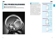
Double Row Roller <strong>Bearings</strong><br />
Double Row Roller <strong>Bearings</strong> NNU49.. are separable, thus enabling their easy mounting and dismounting in<br />
bedding. Both bearing rings are always fitted with offset. They are primarily designed for rolling mountings of<br />
machine tools spindles and enable applications in transfer of higher radial loads and high precision run. They<br />
are fitted with two rows of cylinders centered in outer rings raceways. The inner ring is plain, allowing axial<br />
displacement at bearing operation in mounting. The bearing is provided with single-piece brass prong-type<br />
cage guided on rolling elements.<br />
The supporting surfaces of double row cylindrical roller bearings must not be misaligned.<br />
Precision execution of double row cylindrical roller bearings permits to reach high speed frequencies.<br />
Bearing outer rings are provided with peripheral groove with three lubricating holes for easy lubrication<br />
(supplementary suffix S).<br />
The inner design of bearings is an outcome of development knowledge utilization and is optimized for ideal stress<br />
distribution in maximum length of rolling contact, with elimination of its concentration on peripheral parts.<br />
<strong>Bearings</strong> are manufactured and supplied in tolerance classes P6, P5 and P4 and in radial internal clearances<br />
below standard C1NA, C2, in standard radial internal clearance CN and in clearances higher than standard<br />
C3, C4 and C5. Further they are available also in narrower range of radial internal clearances C4H, C3M and<br />
C2L.<br />
The measurements of boundary dimensions and mounting radius conform to specifications of ISO 15 and<br />
ISO 355 standards.<br />
Bearing rings and cylinders in order of size are manufactured from bearing steel 100Cr6, 100CrMnMo7<br />
stabilized for operation up to + 150 °C, optionally for higher operating temperatures (up to + 200 °C – designation<br />
S1, up to + 250 °C – designation S2, up to + 300 °C – designation S3).<br />
Basic dynamic load rating of bearings Cr is calculated according to ISO 281, basic static load rating of bearings<br />
Cor is calculated according to ISO 76.<br />
Designation Scheme<br />
NNU4920SMP53<br />
Tolerance class P5<br />
Radial clearance C3<br />
Machined brass cage rolling elements centered<br />
Peripheral groove on outer ring surface<br />
with 3 lube holes (120° apart)<br />
Bearing bore diameter = quintuple of bore designation (last 2 digits)<br />
(Example: NNU 4920, d = 5 by 20 = 100 mm)<br />
Diameter series 4<br />
Width series 9<br />
Double row cylindrical roller bearing<br />
D o u b l e R o w R o l l e r B e a r i n g s 0 4 1
Double Row Roller <strong>Bearings</strong><br />
<br />
<br />
<br />
<br />
<br />
Hřídel<br />
Shaft<br />
Árbol<br />
Označení ložiska<br />
Bearing Designation<br />
Denominación<br />
del rodamiento<br />
Hlavní rozměry<br />
Dimension<br />
Dimensiones<br />
Hmotnost<br />
Mass<br />
Peso<br />
Základní únosnost<br />
Basic Load Rating<br />
Capacidad de carga elemental<br />
stat.<br />
dyn.<br />
Mezní únavové<br />
zatížení<br />
Fatique stress limit<br />
Limite de fatiga de<br />
le carga<br />
Mezní frekv.<br />
otáč.<br />
Limiting Speed<br />
Velocidad lim.<br />
de giro para<br />
d D B r s min ns F E Co C Cu ng<br />
mm mm mm mm mm mm mm kg kN kN kN min-1<br />
100 NNU4920M 100 140 40 1,1 6,5 113 1,9 253 128 36 4810<br />
105 NNU4921M 105 145 40 1,1 6,5 118 2,0 261 130 32 4630<br />
110 NNU4922M 110 150 40 1,1 6,5 123 2,0 276 134 34 4460<br />
120 NNU4924M 120 165 45 1,1 6,5 134,5 2,9 341 175 42 4030<br />
130 NNU4926M 130 180 50 1,5 6,5 146 3,8 403 206 49 3680<br />
140 NNU4928M 140 190 50 1,5 6,5 156 4,1 430 213 53 3470<br />
150 NNU4930M 150 210 60 2 6,5 168,5 6,0 642 325 79 3130<br />
160 NNU4932M 160 220 60 2 6,5 178,5 6,4 666 329 82 2980<br />
170 NNU4934M 170 230 60 2 6,5 188,5 6,7 711 342 87 2840<br />
180 NNU4936M 180 250 69 2 9,5 202 6,7 944 450 116 2600<br />
190 NNU4938M 190 260 69 2 9,5 212 10,2 1006 467 123 2500<br />
200 NNU4940M 200 280 80 2,1 12,2 225 14,5 1155 547 141 2310<br />
220 NNU4944M 220 300 80 2,1 12,2 245 15,7 1234 564 151 2160<br />
240 NNU4948M 240 320 80 2,1 12,2 265 16,8 1314 580 161 2020<br />
260 NNU4952M 260 360 100 2,1 15 292 29,6 1983 870 209 1790<br />
280 NNU4956M 280 380 100 2,1 15 312 31,4 2109 898 223 1690<br />
300 NNU4960M 300 420 118 3 17,7 339 48,7 2665 1156 281 1520<br />
320 NNU4964M 320 440 118 3 17,7 359 53,6 2838 1196 300 1450<br />
340 NNU4968M 340 460 118 3 17,7 379 56,3 2929 1210 309 1390<br />
360 NNU4972M 360 480 118 3 17,7 399 59,2 3102 1248 328 1330<br />
380 NNU4976M 380 520 140 4 17,7 426 87,5 3971 1610 419 1230<br />
400 NNU4980M 400 540 140 4 17,7 446 91,7 4210 1665 445 1180<br />
420 NNU4984M 420 560 140 4 17,7 466 95,4 4336 1685 458 1140<br />
440 NNU4988M 440 600 160 4 17,7 490 133,0 5298 2082 560 1060<br />
460 NNU4992M 460 620 160 4 17,7 510 138,0 5607 2153 592 1020<br />
480 NNU4996M 480 650 170 5 17,7 534 163,0 6106 2347 645 980<br />
500 NNU49/500M 500 670 170 5 17,7 554 169,0 6285 2378 664 950<br />
530 NNU49/530M 530 710 180 5 17,7 585 201,0 8250 3064 742 890<br />
560 NNU49/560M 560 750 190 5 17,7 618 241,0 8860 3281 797 840<br />
600 NNU49/600M 600 800 200 5 17,7 666 282,0 10249 3602 922 790<br />
630 NNU49/630M 630 850 218 6 23,5 704 359,0 11393 4146 1025 740<br />
670 NNU49/670M 670 900 230 6 23,5 738 408,0 13868 5110 1248 700<br />
710 NNU49/710M 710 950 243 6 23,5 782 489,0 15893 5698 1430 660<br />
800 NNU49/800M 800 1060 258 6 23,5 880 626,0 17620 6234 1332 600<br />
850 NNU49/850M 850 1120 272 6 23,5 931 726,0 18000 6300 1435 500<br />
900 NNU49/900M 900 1180 280 6 23,5 986 817,0 20400 7100 1628 480<br />
0 4 2 D o u b l e R o w R o l l e r B e a r i n g s
S P H E R I C A L R O L L E R T H R U S T B E A R I N G S
SPHERICAL ROLLER THRUST BEARINGS<br />
Spherical roller thrust bearings comprise a consistent, entire manufacturing program both in dimensional and<br />
design series 292, 293 and 294, being in compliance with the international standards ISO by their design and<br />
manufacturing process. Quality management system of the whole manufacturing process of spherical roller<br />
thrust bearings is certified according to international standards series 9000.<br />
Contrary to other thrust bearings the spherical roller thrust bearings loads are transferred from one raceway to<br />
the other under certain angle; this enables to accommodate also radial load in addition to axial load. Spherical<br />
roller thrust bearings are separable, therefore the shaft ring with cage and spherical rollers and housing<br />
(outer) ring can be installed individually. Another important feature of these bearings is their ability to tilt, which<br />
allows the possibility of alignment of shaft deflection and of verticality deviation to the housing.<br />
Spherical roller thrust bearings are produced, in dependence to size and type, in two designs – in standard<br />
and E design. Outstanding feature of bearings of E design are their higher utility parameters, they represent a<br />
new generation of spherical roller thrust bearings. Being of identical main dimensions, they have upper utility<br />
properties. Both designs can be produced with machined brass cage M or with steel sheet cage J.<br />
Should a bearing with machined brass cage, in which acting axial forces were accommodated also by housing<br />
for cage centering, be replaced by bearing with pressed steel sheet cage, a distance ring must be inserted<br />
between shaft ring and shaft shoulder.<br />
The inner space of spherical roller thrust bearings can be efficiently utilized. Therefore they are suitable for<br />
accommodation of great load at relatively high speed frequency. The bearings are capable to accommodate<br />
in addition to axial load also certain radial forces, anyhow these must be of smaller value than 55 percent<br />
of simultaneously acting axial force. Housing ring spherical raceway enables to align verticality deviations<br />
between the shaft and housing.<br />
For their high utility values the spherical roller thrust bearings find wide application in many fields and industrial<br />
sectors. They are mainly used in the following installations:<br />
– medium and heavy-duty forming machines<br />
– ship drive shafts<br />
– drilling rigs of all types and sizes<br />
– medium and heavy-duty cranes including crane hooks<br />
– pumps of medium and large sizes and capacities<br />
– mining tunnelling machines and mining engineering<br />
– heavy load swivelling turntables of installations in open pit mines and stone quarries<br />
– power plant engineering (turbines, generating sets, electric motors).<br />
Designation of Spherical Roller Thrust <strong>Bearings</strong><br />
S P H E R I C A L R O L L E R T H R U S T B E A R I N G S 0 4 5
Boundary Dimensions<br />
Boundary dimensions of spherical roller thrust bearings shown in dimensional tables comply with international<br />
dimensional plan ISO.<br />
Self Alignment<br />
Design of spherical roller thrust bearings allows tilting and thus alignment of shaft verticality deviation to rolling<br />
elements, while shaft deflection (to certain magnitude) has no influence on bearing operation. Under normal<br />
acting load F a<br />
+ 2,7·F r<br />
= 0,05·C oa<br />
, shaft ring rotation, constant verticality deviations and usual operating conditions<br />
the tilting of spherical roller thrust bearings off central position is allowed by values shown in the table,<br />
without impairing their correct function:<br />
Under growing load the permitted tilting diminishes. For instance, under load F a<br />
+ 2,7·F r<br />
= 0,15·C oa<br />
the permitted<br />
tilting of all bearing types is approx. 1.5°. Taking advantage of permitted tilting depends also on sealing<br />
type and arrangement design.<br />
Cages<br />
Spherical roller thrust bearings in standard version have machined brass cages centered by shaft ring steel<br />
bush and bear designation M. The version with steel sheet cage centered by shaft ring are marked by letter<br />
J. Spherical roller thrust bearings with steel sheet cage are interchangeable with bearings with brass cage,<br />
anyhow, when replacing brass cage bearings with bearings with steel sheet cage bearings it is necessary to<br />
use distance rings (see drawing in tabular part).<br />
Review of <strong>Bearings</strong> Executions<br />
Types M, EM<br />
M<br />
Standard bearing version with machined brass cage centered by shaft ring<br />
steel guiding bush<br />
EM Bearing with better utilized inner space with higher utility parameters, with<br />
machined brass cage centered by shaft ring steel guiding bush<br />
Types J, EJ<br />
J Standard bearing version with steel sheet cage centered by shaft ring<br />
EJ Bearing with better utilized inner space with higher utility parameters, with<br />
steel sheet cage centered by shaft ring<br />
Connecting Dimensions<br />
Bearing rings may bear only on facial resting surface on shaft or in housing but not on the transient rounding.<br />
Maximum radius of connected parts r a ma<br />
must therefore be smaller than the minimum dimension<br />
of bearing rings rounding r s<br />
.<br />
Tolerance<br />
Spherical roller thrust bearings are generally manufactured in normal tolerance class P0 (this symbol is not<br />
shown in the designation). The limiting tolerance values are shown in ISO 492. Production of bearings of<br />
higher tolerance class needs to be negotiated with the manufacturer.<br />
0 4 6<br />
S P H E R I C A L R O L L E R T H R U S T B E A R I N G S
Operating Temperature Effect on <strong>Bearings</strong> Material<br />
All ZKL spherical roller thrust bearings pass special heat treatment permitting their use under operating temperature<br />
up to +200 °C without inadmissible dimensional changes.<br />
Design of Connecting Parts<br />
Connecting dimensions d a<br />
and D a<br />
shown in dimensional tables apply for loads up to F a<br />
= 0.1·C oa<br />
. Should<br />
a greater load act on the bearing, we recommend to rest both the shaft and housing rings by rings entire<br />
facial surfaces (d a<br />
= d 1<br />
a D a<br />
= D 1<br />
) and simultaneously to support the housing ring radially too. In such cases<br />
it is desirable to contact the technical and Consulting Services department of ZKL – Vyzkum a vyvoj, a. s. for<br />
advice. When using the bearings of J, EJ design with steel sheet cages it is appropriate to enlarge the housing<br />
bore near to the cage to prevent thus contact of housing with cage at bearing tilt. Recommended diameter<br />
value of this recess is D + 15 mm for bearings of outer diameter up to 380 mm (inclusive) and D + 20 mm for<br />
larger bearings.<br />
Lubrication<br />
We recommend to generally lubricate spherical roller thrust bearings by oil. Only under very low speed frequency<br />
and small load, when bearings with steel sheet cage are used, lubrication by grease may be chosen.<br />
When using grease, the shaft in horizontal position is more suitable than vertical. The permissible speed frequency<br />
of vertically oriented shaft lubricated by grease is just a half of a shaft positioned horizontally.<br />
The inner design of spherical roller thrust bearings develops a pumping effect under operation, which can be<br />
found useful under specific circumstances and which should be taken in consideration when designing the<br />
lubrication and sealing<br />
Minimum Load<br />
Rolling bearings under operation must be exposed to certain minimum load to secure their satisfactory operation.<br />
This applies to spherical roller thrust bearings as well and particularly for operation at higher speeds,<br />
when inertial forces of spherical rollers and of cage, plus friction in lubricant may have adverse influence on<br />
rolling and may result in damage of rings raceways and of spherical rollers by slipping.<br />
The needed minimum load for such cases can be estimated from this relation:<br />
( )<br />
n<br />
____<br />
F am<br />
= 1.8 · F r<br />
+ M ·<br />
1000<br />
where<br />
F am<br />
F r<br />
M<br />
n<br />
. . . minimum axial load [N]<br />
. . . radial element of acting combined load [N]<br />
. . . minimum load coefficient – see bearing tables<br />
. . . speed frequency [min-1]<br />
If 1.8 · F r<br />
< 0,0005 · C oa<br />
, it is necessary to substitute in the above equation 1.8·F r<br />
by 0.0005·C oa<br />
.<br />
C oa<br />
. . . basic static load rating [N]<br />
As a rule the mass of parts accommodated by the bearing along with external acting forces exceed the required<br />
minimum load. Should it not be the case, the bearing must be loaded by a supplementary force, such<br />
as by springs.<br />
S P H E R I C A L R O L L E R T H R U S T B E A R I N G S 0 4 7
Equivalent Dynamic Load<br />
Spherical roller thrust bearings can accommodate also radial load in a certain extent, but only under a simultaneously<br />
acting axial load. On condition that F r<br />
≤ 0.55·F a<br />
, it is established that<br />
P ea<br />
= F a<br />
+ 1.2 · F r<br />
where<br />
P ea<br />
F a<br />
F r<br />
. . . equivalent dynamic load [N]<br />
. . . axial load [N]<br />
. . . radial load [N]<br />
If the mounting is arranged so that the axial and radial run-outs can be aligned by relative motions between<br />
rings, and provided that<br />
F r<br />
≤ 0.55 · F a<br />
potom P ea<br />
= 0.88 · (F a<br />
+ 1.2 · F r<br />
)<br />
If F r<br />
> 0.55 F a<br />
, please kindly contact Technical and Consulting Services department of ZKL – Vyzkum a vyvoj,<br />
a. s., who can suggest a suitable solution of the problem.<br />
Equivalent Static Load<br />
For spherical roller thrust bearings it is established (on condition that F r<br />
≤ 0.55·F a<br />
) that<br />
P oae<br />
= F a<br />
+ 2.7 · F r<br />
If F r<br />
> 0.55 F a<br />
, please kindly contact Technical and Consulting Services department of ZKL – Vyzkum a vyvoj,<br />
a. s., who can suggest a suitable solution of the problem.<br />
0 4 8<br />
S P H E R I C A L R O L L E R T H R U S T B E A R I N G S
SPHERICAL ROLLER THRUST BEARINGS<br />
d = 50 to 110 mm<br />
Boundary Dimensions<br />
d D H r s<br />
min<br />
mm<br />
Mass<br />
kg<br />
Basic Load Rating<br />
Dynamic<br />
Static<br />
c a<br />
c oa<br />
kN<br />
Minimum Axial<br />
Load Coefficient<br />
M<br />
Limiting Speed<br />
Frequency for<br />
Oil Lubrication<br />
min -1<br />
Bearing Designation<br />
50 110 36 1.5 1.67 290 930 0.11 3100 29410EJ<br />
60 130 42 1.2 2.47 382 1004 0.13 2600 29412EJ<br />
60 130 42 1.5 2.6 287 809 0.082 2400 29412M*<br />
65 140 45 2 3.26 434 1155 0.14 2400 29413EJ<br />
65 140 45 2 3.3 340 973 0.12 2200 29413M*<br />
70 150 48 2 3.98 464 1268 0.16 2200 29414EJ<br />
70 150 48 2 4 371 1070 0.14 2000 29414M*<br />
75 160 51 2 4.9 524 1465 0.18 2200 29415EJ<br />
75 160 51 2 4.9 429 1250 0.2 2000 29415M*<br />
80 170 54 2.1 5.8 570 1430 0.26 2000 29416EJ<br />
80 170 54 2.1 5.8 464 1370 0.23 1900 29416M*<br />
85 180 58 2 6.67 692 1945 0.24 1800 29417EJ<br />
85 180 58 2.1 6.9 527 1570 0.31 1800 29417M*<br />
90 190 60 2.1 7.77 703 2172 0.4 1800 29418EJ<br />
90 190 60 2.1 8.1 578 1780 0.4 1700 29418M*<br />
100 170 42 1.5 3.95 436 1400 0.58 2000 29320EJ<br />
100 210 67 2.5 10.8 865 2578 0.59 1600 29420EJ<br />
100 210 67 3 11.8 705 2170 0.59 1500 29420M*<br />
110 190 48 2 5.4 570 1760 0.39 1600 29322EJ<br />
110 190 48 2 5.5 442 1420 0.25 1600 29322M*<br />
110 230 73 2.5 13.5 1022 3078 0.85 1400 29422EJ<br />
110 230 73 3 14.5 817 2600 0.85 1400 29422M*<br />
Notice: Deliveries of bearings marked * need to be negotiated with manufacturer<br />
0<br />
5 0<br />
S P H E R I C A L R O L L E R T H R U S T B E A R I N G S
Dimensions<br />
Connecting Dimensions<br />
d<br />
d 1 D 1 B B 2 B 1 B 3 h A<br />
mm<br />
d a<br />
min<br />
D a<br />
max<br />
r s<br />
max<br />
mm<br />
d b1<br />
max<br />
d b2<br />
max<br />
50 95 70 25 13 32 20.5 32 70 90 1.5 56 60.5<br />
60 118 87 27 27 37 20 38 90 117 1.5 67 67<br />
60 118 88 39.5 15 20 38 90 109 1.5<br />
65 128 93 29.5 16 39 21 42 100 118 2 72 72<br />
65 128 96.5 42.5 16 21 42 100 118 2<br />
70 137 101 31 17 42.5 23 44 105 126 2 77.5 77.5<br />
70 137 102 45.5 17 23 44 105 126 2<br />
75 146 108 33.5 18 47 24 47 115 134 2 82.5 82.5<br />
75 146 109 48 18 24 47 115 134 2<br />
80 155 116 36 19 46.5 24 50 120 141 2 86 95.5<br />
80 155 116 51 19 24 50 120 141 2<br />
85 164 123 37 21 50 28 54 130 153 2 94 94<br />
85 164 125 55 21 28 54 130 153 2<br />
90 174 130 39 22 53 29 56 135 161 2 99 99<br />
90 174 130 57 22 29 56 135 161 2<br />
100 150 128 26.2 15 37.3 20.5 58 130 147 1.5 107 107<br />
100 193 144 53 24 58 32 62 150 175 3 110 110<br />
100 193 144.5 64 24 32 62 150 178 2.5<br />
110 176 143 31 16 42 23 64 145 165 2 113 119.5<br />
110 176 143 45.5 16 23 64 145 165 2<br />
110 209,5 159 47 0 27 64 35 69 165 193 3 120.5 129<br />
110 212 160 69 26 35 69 165 196 2.5<br />
S P H E R I C A L R O L L E R T H R U S T B E A R I N G S 0<br />
5 1
SPHERICAL ROLLER THRUST BEARINGS<br />
d = 120 to 200 mm<br />
Boundary Dimensions<br />
d D H r s<br />
min<br />
mm<br />
Mass<br />
kg<br />
Basic Load Rating<br />
Dynamic<br />
c a<br />
kN<br />
Static<br />
c oa<br />
Minimum Axial<br />
Limiting Speed<br />
Load Coefficient<br />
Frequency for<br />
M<br />
Oil Lubrication<br />
min -1<br />
Bearing Designation<br />
120 210 54 2.1 7.41 680 2500 0.78 1600 29324EJ<br />
120 210 54 2.1 7.6 560 1830 0.42 1400 29324M*<br />
120 250 78 4 17.5 1180 3590 0.91 1300 29424EJ<br />
120 250 78 4 18.1 934 3000 0.91 1300 29424M*<br />
130 225 58 2.1 9.08 765 2950 1.1 1500 29326EJ<br />
130 225 58 2.1 9.3 628 2070 0.54 1300 29326M*<br />
130 270 85 4 21.6 1395 4300 1.6 1200 29426EJ<br />
130 270 85 4 22.5 1090 3540 1.6 1200 29426M*<br />
140 240 60 2.1 10.5 850 3150 1.2 1400 29328EJ<br />
140 240 60 2.1 11 675 2310 0.67 1300 29328M*<br />
140 280 85 4 23 1509 4686 1.8 1200 29428EJ<br />
140 280 85 4 24.2 1130 3750 1.8 1200 29428M*<br />
150 250 60 2.1 10.9 863 3236 1.3 1400 29330EJ<br />
150 250 60 2.1 11.5 697 2430 0.74 1200 29330M*<br />
150 300 90 4 28 1626 5241 2.3 1100 29430EJ<br />
150 300 90 4 29.4 1280 4270 2.3 1100 29430M*<br />
160 270 67 3 14.4 1036 3977 2 1200 29332EJ<br />
160 270 67 3 15.2 807 2810 0.99 1100 29332M*<br />
160 320 95 5 33,3 1800 6550 5,4 1000 29432EJ<br />
160 320 95 5 35.5 1460 4810 2.9 1000 29432M*<br />
170 280 67 3 15.1 1058 4098 2.1 1200 29334EJ<br />
170 280 67 3 16 833 2950 1.1 1100 29334M*<br />
170 340 103 5 43.7 1620 5380 3.6 940 29434M<br />
180 300 73 3 19.1 1243 4813 2.9 1100 29336 EJ<br />
180 300 73 3 20.3 984 3530 1.6 1000 29336M*<br />
180 360 109 5 52 1800 6010 4.5 890 29436M<br />
190 320 78 4 23.3 1440 4840 2.9 1100 29338EJ<br />
190 320 78 4 24.8 1120 4010 2 940 29338M*<br />
190 380 115 5 60 1960 6610 5.5 840 29438M<br />
200 280 48 2.1 8.76 710 3150 1.4 1150 29240EM<br />
200 340 85 4 29 1620 5480 3.8 950 29340EJ<br />
200 340 85 4 33 1300 4740 2.8 890 29340M*<br />
200 400 122 5 69 2210 7510 7.1 790 29440M<br />
Notice: Deliveries of bearings marked * need to be negotiated with manufacturer<br />
0<br />
5 2<br />
S P H E R I C A L R O L L E R T H R U S T B E A R I N G S
Dimensions<br />
Connecting Dimensions<br />
d<br />
d 1 D 1 B B 2 B 1 B 3 h A<br />
mm<br />
120 187.1 155.5 35.5 19 47 27 70 160 181 2 128 128<br />
120 194 157.5 51 18 26 70 160 184 2<br />
120 226.8 173 50.5 29 69.5 37 74 180 209 3 132 143<br />
120 229 172 74 29 37 74 180 212 3<br />
130 201.5 165.7 37.5 21 49.6 30.1 76 175 194 2 138 143<br />
130 205 170 55 19 28 76 170 198 2<br />
130 245 188 54 31 74 41 81 195 227 3 142.5 153<br />
130 247 188 81 31 41 81 195 229 3<br />
140 214.9 178.9 38.5 22 52.4 30 82 185 208 2 148 154<br />
140 219 183 57 20 29 82 185 211 2<br />
140 254 196.5 54 32 74 41 86 205 239 3 157 166<br />
140 257 197.5 81 31 41 86 205 239 3<br />
150 222.5 189.6 38 22 53.8 28 87 195 219 2 158 163<br />
150 229 193 57 20 29 87 195 222 2<br />
150 273 209.5 58 34 79 44 92 220 253 3 163 175<br />
150 276 211.5 86 32 44 92 220 257 3<br />
160 243.6 202.3 42 24 58.6 33 92 210 235 2.5 169 176<br />
160 248 207 64 23 32 92 210 239 2.5<br />
160 282,8 221,7 60,5 35 82 45,5 99 235 270 4 175 189<br />
160 306 226 91 34 45 99 230 274 4<br />
170 253.6 214.6 42.2 24 60 32 96 220 245 2.5 178 188<br />
170 258 215 64 23 32 96 220 248 2.5<br />
170 324 240 99 37 50 104 245 291 4<br />
180 270.4 228.3 46 26 64.3 35.5 103 235 262 2.5 189 195<br />
180 277 231 69 25 35 103 235 266 2.5<br />
180 342 255 105 39 52 110 260 307 4<br />
190 284.4 239.5 49 28 68 36 110 250 280 3 200 211<br />
190 308 246 74 27 38 110 250 283 3<br />
190 360 270 111 41 55 117 275 325 4<br />
200 264 233 32 45 17 24 108 235 260 2<br />
200 302.8 253.6 53.5 29 73 40 116 265 297 3 211 224<br />
200 325 261 81 29 41 116 265 300 3<br />
200 380 284 117 43 59 122 290 343 4<br />
d a<br />
min<br />
D a<br />
max<br />
r s<br />
max<br />
mm<br />
d b1<br />
max<br />
d b2<br />
max<br />
S P H E R I C A L R O L L E R T H R U S T B E A R I N G S 0<br />
5 3
SPHERICAL ROLLER THRUST BEARINGS<br />
d = 220 to 320 mm<br />
Boundary Dimensions<br />
d D H r s<br />
min<br />
mm<br />
Mass<br />
kg<br />
Basic Load Rating<br />
Dynamic<br />
Static<br />
c a<br />
c oa<br />
kN<br />
Minimum Axial<br />
Load Coefficient<br />
M<br />
Limiting Speed<br />
Frequency for<br />
Oil Lubrication<br />
min -1<br />
Bearing Designation<br />
220 300 48 2 9.64 735 3350 1.4 1300 29244EM<br />
220 360 85 4 31.6 1740 6300 5 950 29344EJ<br />
220 360 85 4 32.8 1340 4970 3.1 840 29344M*<br />
220 420 122 6 74 2260 7970 7.9 750 29444M<br />
240 340 60 2.1 16.7 770 3450 1.5 890 29248M<br />
240 380 85 4 33.4 1790 6490 5.3 900 29348EJ<br />
240 380 85 4 35.3 1340 5190 3.4 790 29348M*<br />
240 440 122 6 79 2340 8420 8.9 750 29448M<br />
260 360 60 2.1 18.5 801 3650 1.7 890 29252M<br />
260 420 95 5 46.9 2240 8310 8.6 800 29352EJ<br />
260 420 95 5 48.5 1780 6820 5.8 750 29352M*<br />
260 480 132 6 105 2730 9870 12 670 29452M<br />
280 380 60 2.1 19.5 847 3950 2 840 29256M<br />
280 440 95 5 49.5 2310 8490 9 800 29356EJ<br />
280 440 95 5 52.5 1780 7100 6.3 710 29356M*<br />
280 520 145 6 127 4470 15750 31 650 29456EJ<br />
280 520 145 6 132 3230 11840 18 630 29456M*<br />
300 420 73 3 30.5 1030 4670 2.7 750 29260M<br />
300 480 109 5 68.7 2650 11000 15 700 29360EJ<br />
300 480 109 5 74 2180 8500 9 630 29360M*<br />
300 540 145 6 133 4510 16460 34 630 29460EJ<br />
300 540 145 6 140 3220 11850 18 600 29460M*<br />
320 440 73 3 32.9 1070 4930 3 710 29264M<br />
320 500 109 5 72.1 2850 10920 15 670 29364EJ<br />
320 500 109 5 77 2180 8850 9.8 630 29364M*<br />
320 580 155 7.5 164 5010 21200 56 600 29464EJ<br />
320 580 155 7.5 164 3890 14690 27 560 29464M*<br />
Notice: Deliveries of bearings marked * need to be negotiated with manufacturer<br />
0<br />
5 4<br />
S P H E R I C A L R O L L E R T H R U S T B E A R I N G S
Dimensions<br />
Connecting Dimensions<br />
d<br />
d 1 D 1 B B 2 B 1 B 3 h A<br />
mm<br />
d a<br />
min<br />
D a<br />
max<br />
r s<br />
max<br />
mm<br />
d b1<br />
max<br />
d b2<br />
max<br />
220 286 252 46 17 24 117 285 260 2<br />
220 324.4 273 55 29 74 41 125 285 316 3 229 240<br />
220 345 280 81 29 41 125 285 320 3<br />
220 400 305 117 43 58 132 310 364 5<br />
240 330 283 57 19 30 130 285 311 2<br />
240 343.7 294.8 54 29 75 40.5 135 305 336 3 249 259<br />
240 365 300 81 29 41 135 300 340 3<br />
240 420 321 117 43 59 142 330 383 5<br />
260 350 302 57 19 30 139 305 331 2<br />
260 380.3 320.4 61 32 84 46 148 3350 370 4 273 286<br />
260 405 325 91 32 45 148 330 374 3<br />
260 460 346 127 48 64 154 360 419 5<br />
280 370 323 57 19 30 150 325 351 2<br />
280 401.7 342.1 62 32 84 45 158 355 390 4 293 305<br />
280 423 345 91 32 46 158 350 394 4<br />
280 468.9 370 95 52 125 70 166 395 446 5 300 320<br />
280 495 380 140 52 68 166 390 453 5<br />
300 405 355 69 21 38 162 355 386 2.5<br />
300 431.9 366.7 70 36 95 51 168 385 423 4 313 329<br />
300 460 375 105 37 50 168 380 429 4<br />
300 489.2 370 95 55 125 70 175 415 465 5 319 340<br />
300 515 398 140 52 70 175 410 471 5<br />
320 430 375 69 21 38 172 375 406 2.5<br />
320 456.1 387 68 37 95 53 180 405 442 4 332 347<br />
320 482 395 105 37 53 180 400 449 4<br />
320 525.6 422 102 55 134 74.5 191 450 500 6 344 367<br />
320 555 430 149 55 75 191 435 507 6<br />
S P H E R I C A L R O L L E R T H R U S T B E A R I N G S 0<br />
5 5
SPHERICAL ROLLER THRUST BEARINGS<br />
d = 340 to 800 mm<br />
Boundary Dimensions<br />
d D H r s<br />
min<br />
mm<br />
Mass<br />
kg<br />
Basic Load Rating<br />
Dynamic<br />
Static<br />
c a<br />
c oa<br />
kN<br />
Minimum Axial<br />
Load Coefficient<br />
M<br />
Limiting Speed<br />
Frequency for<br />
Oil Lubrication<br />
min -1<br />
Bearing Designation<br />
340 540 122 5 103 2640 10550 14 560 29368M<br />
340 620 170 7.5 211 5820 25080 66 380 29468EJ<br />
340 620 170 7.5 218 4350 16410 34 500 29468M*<br />
360 500 85 4 51.8 1400 6600 5.4 630 29272M<br />
360 560 122 5 107 2650 11030 15 560 29372M<br />
380 520 85 4 52.8 1550 7510 7.1 600 29276M<br />
380 670 175 7.5 263 4700 19100 46 490 29476EM<br />
400 540 85 4 55.3 1600 7900 7.8 600 29280M<br />
400 620 132 6 150 3290 14120 25 500 29380M<br />
400 506 185 7.5 306 6810 26500 88 450 29480EM<br />
420 650 140 6 170 3410 14700 27 450 29384M<br />
420 730 185 7,5 308 6850 31020 63 430 29484EM<br />
440 680 145 6 190 3860 16850 35 450 29388M<br />
440 780 206 9.5 407 6280 24650 76 400 29488M<br />
480 850 224 9.5 518 9646 44398 82 340 29496EM<br />
500 670 103 5 101 2400 12120 18 470 292/500M<br />
500 750 150 6 220 4220 18660 44 400 293/500M<br />
500 870 224 9,5 548 10025 48568 290 340 294/500 EM<br />
530 800 160 7.5 286 5130 22730 65 380 293/530M<br />
600 900 180 7.5 390 6800 31500 120 330 293/600EM<br />
630 850 132 6 211 4250 22500 63 350 292/630M<br />
800 1360 335 15 2010 16340 72360 650 220 294/800M<br />
Notice: Deliveries of bearings marked * need to be negotiated with manufacturer<br />
0<br />
5 6<br />
S P H E R I C A L R O L L E R T H R U S T B E A R I N G S
Dimensions<br />
Connecting Dimensions<br />
d<br />
d 1 D 1 B B 2 B 1 B 3 h A<br />
mm<br />
d a<br />
min<br />
D a<br />
max<br />
r s<br />
max<br />
mm<br />
d b1<br />
max<br />
d b2<br />
max<br />
340 520 424 117 41 59 192 430 484 4<br />
340 561.8 442.2 112 54 146 84 201 475 530 6<br />
340 590 452 164 61 82 201 465 451 6<br />
360 485 420 81 25 44 194 420 461 3<br />
360 540 444 117 41 59 202 450 504 4<br />
380 505 440 81 27 42 202 440 480 3<br />
380 622 504 168 63 85 222 504 570 6<br />
400 526 460 81 27 42 212 460 500 3<br />
400 596 494 127 44 64 225 498 557 5<br />
400 651 530 178 67 89,5 234 550 615 6<br />
420 626 520 135 48 68 235 523 585 5<br />
420 663 540 175 67 90 244 592 684 8<br />
440 655 546 140 49 70 245 548 614 5<br />
440 745 576 199 74 100 260 592 684 8<br />
480 772 611.6 214 81 108 280 660 735 8<br />
500 654 574 99 33 55 268 578 622 4<br />
500 725 611 144 51 74 280 613 680 5<br />
801 625,6 218 81 110 290 685 755 8<br />
530 772 648 154 54 76 295 651 724 6<br />
600 850 731 171 64 87 335 735 815 6<br />
630 820 724 127 42 67 338 730 789 5<br />
800 1300 1040 324 120 162 462 1055 1200 12<br />
S P H E R I C A L R O L L E R T H R U S T B E A R I N G S 0<br />
5 7
S P E C I A L B E A R I N G S
SPECIAL BEARINGS<br />
In addition to standard assortment of bearings specified in this Group catalogue the production in ZKL<br />
Group gradually expanded by a number of special bearings based on clients‘ requirements and on industrial<br />
sectors development.<br />
These are standardized bearings for special machines and use developed and produced on clients‘ wishes<br />
and requirements upon consultations with professionals in bearings design and manufacture.<br />
By virtue of lasting experiences ZKL Group is continuously prepared to render assistance to its existing and<br />
new clients by its development base, ZKL – Vyzkum a vyvoj, a. s., in professional advisory and consulting<br />
services in the fields of design, mounting, technical parameters calculation, as well as in all requirements of<br />
new bearings development.<br />
S P E C I A L B E A R I N G S 0 6 1
SPECIAL BEARINGS<br />
0 6 2<br />
S P E C I A L B E A R I N G S
S P E C I A L B E A R I N G S 0 6 3
SPECIAL BEARINGS<br />
0 6 4<br />
S P E C I A L B E A R I N G S
S P E C I A L B E A R I N G S 0 6 5
SPECIAL BEARINGS<br />
0 6 6<br />
S P E C I A L B E A R I N G S
S P E C I A L B E A R I N G S 0 6 7
SPECIAL BEARINGS<br />
0 6 8<br />
S P E C I A L B E A R I N G S
S P E C I A L B E A R I N G S 0 6 9
SPECIAL BEARINGS<br />
0 7 0<br />
S P E C I A L B E A R I N G S
SPECIAL BEARINGS<br />
Bearing<br />
Designation<br />
Boundary Dimensions<br />
d D B r smin<br />
mm<br />
r 1smin<br />
d 1<br />
d 2<br />
F<br />
Special Single Row Radial Cylidrical Roller <strong>Bearings</strong><br />
For Railway Rolling Stock Axles<br />
Basic load<br />
rating<br />
Capacidad<br />
PLC 410 – 13 120 240 80 3 7,5 160,8 150 553 742 160 0,120 0,160 0,300 0,900 P0<br />
PLC 410 – 14 120 240 80 3 7,5 160,8 150 553 742 160 0,120 0,160 0,300 0,900 P0<br />
PLC 410 – 15 130 240 80 3 7,5 170,5 159 517 752 160 0,135 0,180 0,300 0,900 P0<br />
PLC 410 – 16 130 240 80 3 7,5 170,5 159 517 752 160 0,135 0,180 0,300 0,900 P0<br />
dyn.<br />
C r<br />
kN<br />
stat.<br />
C or<br />
Max.<br />
speed<br />
of<br />
railway<br />
car<br />
km h -1<br />
Radial<br />
clearance<br />
mm<br />
Axial<br />
clearance<br />
Min. Max. Min. Max.<br />
Precision<br />
class<br />
S P E C I A L B E A R I N G S 0 7 1
SPECIAL BEARINGS<br />
PLC 412–11<br />
B 1<br />
øD<br />
ød<br />
B<br />
Boundary Dimensions<br />
Basic Load Rating<br />
Dynamic Static<br />
Mass<br />
Bearing<br />
Designation<br />
d D B B 1<br />
C r<br />
C or<br />
mm<br />
kN<br />
kg<br />
260 431,8 170 96,8 1140 1940 86,5 PLC 412–11<br />
PLC 510–20<br />
B<br />
øD<br />
ød<br />
B 1<br />
Boundary Dimensions<br />
Basic Load Rating<br />
Dynamic Static<br />
Mass<br />
Bearing<br />
Designation<br />
d D B B 1<br />
C r<br />
C or<br />
mm<br />
kN<br />
kg<br />
111,16 215 90 76 564 803 14,4 PLC 510–20<br />
0 7 2<br />
S P E C I A L B E A R I N G S