Oxy-Coal Combustion - Eventos del Instituto de IngenierÃa, UNAM
Oxy-Coal Combustion - Eventos del Instituto de IngenierÃa, UNAM
Oxy-Coal Combustion - Eventos del Instituto de IngenierÃa, UNAM

You also want an ePaper? Increase the reach of your titles
YUMPU automatically turns print PDFs into web optimized ePapers that Google loves.
Development in<br />
<strong>Oxy</strong>fuel <strong>Combustion</strong> Technologies for<br />
<strong>Coal</strong> Fired Power Plants with CCS<br />
(Part 1: Boiler and Burner Development)<br />
Stanley Santos<br />
IEA Greenhouse Gas R&D Programme<br />
Cheltenham, UK<br />
<strong>Instituto</strong> <strong>de</strong> Inginieria <strong>UNAM</strong><br />
28 th March ac 2012
CO2 Capture Options<br />
EPRI 2007<br />
2
<strong>Oxy</strong>-<strong>Coal</strong> <strong>Combustion</strong> Power Plant<br />
Air<br />
<strong>Oxy</strong>gen<br />
Air<br />
separation<br />
Recycled flue gas<br />
Vent<br />
Fuel Boiler Cooling Purification/<br />
(+FGD) compression<br />
CO 2<br />
Steam<br />
Steam<br />
turbine<br />
Power<br />
3<br />
3
<strong>Oxy</strong>-<strong>Combustion</strong> Technology<br />
• Use of oxygen instead of air in a boiler – “<strong>Oxy</strong>-<br />
<strong>Combustion</strong>” is a feasible option for power plant<br />
with CO2 capture.<br />
• With significant R&D investment in the past <strong>de</strong>ca<strong>de</strong>, this<br />
technology has achieve a maturity similar to the other<br />
leading options for power generation with CCS<br />
• Outline for Presentation<br />
• Boiler and Burner Development<br />
• Air Separation Unit<br />
• Flue Gas Processing Unit<br />
• CO2 Processing Unit<br />
4<br />
4
<strong>Oxy</strong>fuel <strong>Combustion</strong><br />
Overall Schematic Diagram<br />
5
Where Can You Extract the Recycled Flue Gas (RFG)<br />
(For Practical application using low S coal)<br />
6<br />
6
<strong>Oxy</strong>fuel <strong>Combustion</strong> Technology<br />
BOILER AND BURNER<br />
DEVELOPMENT<br />
7
Development of <strong>Oxy</strong>-Fuel <strong>Combustion</strong> Application in Industry<br />
Adapted from sli<strong>de</strong> of Sho Kobayashi, Praxair<br />
Pictures from IFRF, Air Liqiu<strong>de</strong>, Asahi Glass, Lin<strong>de</strong> Gas<br />
8<br />
8
Historical Perspective – The Early Days<br />
• 1982: Initial suggestion by Abraham et. al.<br />
(OGJ) of using <strong>Oxy</strong>-<strong>Coal</strong> <strong>Combustion</strong> to<br />
produce CO2 for EOR<br />
• 1 st public document looking at capturing CO2 from<br />
flue gas using oxy-combustion.<br />
• However ... as early as 1970’s work has<br />
started din the <strong>de</strong>velopment of oxy-coal<br />
combustion with recycled flue gas<br />
• 1974: Japan initial conception of using oxy-coal combustion for power<br />
generation. (To reduce pollution)<br />
• 1978: Economic feasibility of oxy-coal combustion was investigated for<br />
EOR application (H. Farzan, Babcock & Wilcox / A. Wolsky, ANL)<br />
9<br />
9
Technology Development<br />
Japan’s initial conception of oxyfuel combustion application<br />
for power generation (1974)<br />
<strong>Oxy</strong>gen<br />
3rd Workshop, IEAGHG International <strong>Oxy</strong>-<strong>Combustion</strong><br />
Network, Yokohama, Japan<br />
10
ANL - EERC Study<br />
World’s 1st <strong>Oxy</strong>-<strong>Coal</strong> <strong>Combustion</strong> Industrial Pilot Scale Study<br />
Tower Furnace (~ 3MWth)<br />
11
Convective Section of the boiler<br />
• heat transfer profile<br />
• ash <strong>de</strong>position and fouling issue<br />
Burner <strong>de</strong>sign issue<br />
• Ignition<br />
• flame stability<br />
• <strong>de</strong>volatilisation & char burnout<br />
Radiant Section of the Boiler<br />
• heat transfer profile<br />
• slagging issue<br />
• firesi<strong>de</strong>id corrosion issue<br />
Prior to any retrofit of carbon capture<br />
technology, it is essential to repower<br />
the plant in or<strong>de</strong>r to achieve the<br />
highest possible efficiency<br />
12<br />
12
Composition of Comburent<br />
(Oxidant)<br />
Gas Composition<br />
Air Fired Case<br />
<strong>Oxy</strong>‐<strong>Coal</strong> <strong>Combustion</strong><br />
%v (dry) Pi Primary RFG 2ndary RFG<br />
Nitrogen (N2) 78.1 18 ‐ 12 14 ‐ 10<br />
<strong>Oxy</strong>gen (O2) 20.9 2 ‐ 21 25 ‐ 40<br />
Argon (ar) 0.9 3 ‐ 3.5 3 ‐ 3.5<br />
Carbon Dioxi<strong>de</strong> CO2) 0.04 78 ‐ 60 55 ‐ 40<br />
Water (H2O) %v (wet) < 2 (<strong>de</strong>pend on %RH) 8 ‐ 4 15 ‐ 5<br />
** Calculation based on ~3% air ingress, 95% O2 purity and C 6.87 H 5.56 O 0.56 N 0.13 S 0.03<br />
13<br />
13
Composition of Flue Gas<br />
from Boiler<br />
Gas Composition<br />
%v (dry)<br />
Air Fired Case<br />
<strong>Oxy</strong>‐<strong>Coal</strong> <strong>Combustion</strong> Case<br />
Nitrogen (N2) 80 ‐ 78 14 ‐ 18<br />
<strong>Oxy</strong>gen (O2) 3 ‐ 4 (~3.5) 2 ‐ 5 (~3.5)<br />
Argon (ar) 0.9 ‐ 0.95 3 ‐ 3.5<br />
Carbon Dioxi<strong>de</strong> CO2) 14 ‐ 16 78 ‐ 74<br />
Water (H2O) %v (wet) 6 ‐ 8 20 ‐12<br />
** Calculation based on ~3% air ingress, 95% O2 purity and C 6.87 H 5.56 O 0.56 N 0.13 S 0.03<br />
14 14
Recyled Flue Gas Ratio<br />
Impact to the Flame<br />
Properties<br />
R =<br />
m RFG<br />
m PFG<br />
+ m RFG<br />
15
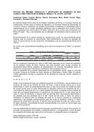
Optimum Recycle Ratio<br />
(Optimum recycle ratio is <strong>de</strong>fined by the amount of Recycled Flue<br />
Gas to match the heat transfer profile of conventional air fired<br />
operation)<br />
Some of the reported results for the optimum flue gas recycle ratio<br />
Burner Rating<br />
Type of Flue Gas<br />
Molar Ratio 1<br />
(CO2 + H2O)/O2<br />
%O2 in<br />
Comburent 2<br />
Recycle Ratio<br />
MRFG/(MRFG + MPFG)<br />
ANL – EERC<br />
3 MWth<br />
partially dried RFG<br />
(~18%v moisture)<br />
266 2.66 26% (wet) -<br />
wet RFG<br />
(~35% moisture)<br />
3.25 22% (wet) ~ 0.68<br />
IFRF<br />
2.5 MWth<br />
wet RFG<br />
(~ 26% moisture)<br />
~ 2.20 48% (~41% wet) ~ 0.58<br />
IHI 1.2 MWth wet RFG - ~34% (30%wet) -<br />
CANMET 0.3 MWth wet RFG - 35% (dry) -<br />
1<br />
Molar ratio of the secondary comburent (oxidant)<br />
2<br />
% oxygen through the burner throat (volume dry basis)<br />
3<br />
MRFG and dMPFG are the mass flow rate of the recycled flue gas and product flue gas respectively<br />
16
Recycle Rate and <strong>Oxy</strong>gen Concentration<br />
Universität ität Stuttgarttt t<br />
a) b)<br />
Flue Gas with Fly Ash<br />
<strong>Oxy</strong>gen<br />
y O2 , mix<br />
t adiabatic<br />
<strong>Coal</strong><br />
Heat Output<br />
Bottom Ash<br />
Source: A. Kather, 2009<br />
17
Factors affecting Recycle<br />
Ratio<br />
• Critical factors affecting the optimum<br />
m<br />
amount of recycled flue gas<br />
• Burner and boiler <strong>de</strong>sign (heat transfer and flame<br />
stability – oxygen distribution through burner)<br />
• Air ingress<br />
• Purity of oxygen from the ASU<br />
• <strong>Coal</strong> type<br />
• Level of moisture content in comburent<br />
• Comburent (oxidant) temperature<br />
18<br />
18
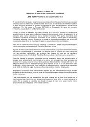
Flame Description – Impact of Recycle Ratio<br />
(Courtesy of IFRF)<br />
Figure 3(a): normal air-fired operation Figure 3(b): O 2 -RFG flame with recycle ratio = 0.58<br />
Figure 3(c): O 2 -RFG flame with recycle ratio = 0.76 Figure 3(d): O 2 -RFG flame with recycle ratio = 0.52<br />
19
<strong>Coal</strong> Flame Photos:<br />
Air Fired vs <strong>Oxy</strong>-Fired<br />
(Courtesy of IHI)<br />
Air mo<strong>de</strong>(O 2 :21%)<br />
<strong>Oxy</strong> mo<strong>de</strong>(O 2 :21%) <strong>Oxy</strong> mo<strong>de</strong>(O 2 :30%)<br />
20<br />
20
<strong>Coal</strong> Flame Photos:<br />
Impact of Recycled Flue Gas<br />
(Courtesy of IFRF)<br />
Recycle Ratio = 0.58<br />
(~ 0.61 inclu<strong>de</strong> the CO2 to transport coal)<br />
Recycle Ratio = 0.76<br />
21<br />
21
Effect of Different <strong>Oxy</strong>gen Concentrations<br />
(and Recycle Rates) on Flame Pattern<br />
Universität ität Stuttgarttt t<br />
Air<br />
<strong>Oxy</strong>fuel<br />
<strong>Oxy</strong>fuel<br />
28% O 2 38% O 2<br />
Recycle rate 77% Recycle rate 66%<br />
Source: J. Smart, 2008<br />
22
Ratio of Convective Heat Transfer Coefficient<br />
(Courtesy of IFRF)<br />
h1 ⎛ Re1<br />
⎞ ⎛ Pr<br />
=<br />
h<br />
⎜<br />
⎟<br />
⎜<br />
0<br />
Re<br />
0 ⎠ ⎝ Pr<br />
n<br />
1<br />
⎞<br />
⎟<br />
⎠<br />
1<br />
3<br />
⎛ k<br />
⎜<br />
⎝ k<br />
⎝ 0 0<br />
1<br />
⎞<br />
⎟<br />
⎠<br />
Effect of Recycle Ratio on Convective heat transfer coefficient [IFRF APG1 Trials]<br />
23<br />
23
Radiative Heat Flux Measurements<br />
(Courtesy of IFRF)<br />
Ellipsoidal Radiometer<br />
Results were also<br />
obtained by:<br />
• ANL-EERC<br />
•CANMET<br />
Data from Narrow Angle<br />
Radiometer is necessary<br />
for radiation mo<strong><strong>de</strong>l</strong>ling<br />
<strong>de</strong>velopment<br />
Radiative Flux Using Ellipsoidal Radiometer in Air<br />
(Baseline) and O 2 /RFG (Flames B with recycle ratio = 0.73<br />
and Flame C with recycle ratio = 0.58) – IFRF APG2 Trials<br />
Research in the past<br />
<strong>de</strong>ca<strong>de</strong> has achieved<br />
better un<strong>de</strong>rstanding to eh<br />
Radiation Principle of<br />
oxyfuel boiler<br />
24
Results: Radiative HT- South African coal – Dry<br />
Recycle<br />
m 2<br />
Radiat tive Heat Flux kW/m<br />
500<br />
450<br />
400<br />
350<br />
300<br />
250<br />
Furnace Heat Flux Measurements<br />
South African coal, <strong>Oxy</strong>fuel (3% O 2 )<br />
SAcoal/Air - 3% O2<br />
<strong>Oxy</strong>fuel RR 65%<br />
<strong>Oxy</strong>fuel RR 68%<br />
<strong>Oxy</strong>fuel RR 70%<br />
<strong>Oxy</strong>fuel RR 72%<br />
<strong>Oxy</strong>fuel RR 75%<br />
200<br />
0 500 1000 1500 2000 2500 3000 3500<br />
Axial Distance from Burner, mm<br />
25
Normalised Convective & Radiative<br />
heat flux – Russian <strong>Coal</strong> - Dry Recycle<br />
tic<br />
e<br />
ed Adiabat<br />
emperature<br />
Normalise<br />
Flame Te<br />
Dry <strong>Oxy</strong>fuel Operation Normalised to Air Operation<br />
Peak Radiation Flux, Convective heat transfer and calculated flame temperature<br />
1.6<br />
Russian coal<br />
1.6<br />
1.4<br />
12 1.2<br />
1<br />
0.8<br />
06 0.6<br />
Measured Convective Heat<br />
Transfer Coefficient i indicates 74%<br />
Recycle is "Air-equivalent"<br />
Normalised Flame Temperature (calculated)<br />
Peak Normalised Heat Flux (measured)<br />
Normalised Convective HTC (measured)<br />
New Build Retrofit Avoid<br />
Calculated dry oxyfuel adiabatic<br />
flame temperatures are<br />
equivalent to air at 69% recycle<br />
Measured Peak Radiative<br />
data indicates 74%<br />
Recycle is "Airequivalent"<br />
0.4<br />
0.4<br />
60% 65% 70% 75% 80%<br />
Effective Recycle Ratio<br />
1.4<br />
12 1.2<br />
1<br />
0.8<br />
06 0.6<br />
e and<br />
ux<br />
ed Radiative<br />
ctive Heat Flu<br />
Normalise<br />
Convec<br />
26
Consi<strong>de</strong>rations in the Boiler Operation<br />
O2 Purity and Air Ingress<br />
(a.) Why not 99+% O2 Purity<br />
(b.) Air Ingress… A Challenge for the Operator<br />
27
Issue of Air Ingress (Air In-leakage)<br />
Air Ingress in the boiler is a<br />
fact of life!!!<br />
1 st Large Scale Demonstration of<br />
<strong>Oxy</strong>-<strong>Coal</strong> <strong>Combustion</strong> (35MWth)<br />
– What Are the Lesson Learned...<br />
28
Problem with Air Ingress<br />
1 st Large Scale <strong>Oxy</strong>-<strong>Coal</strong> <strong>Combustion</strong><br />
Burner Test Experience - International <strong>Combustion</strong> Ltd.<br />
30 MWth Low NOx burner<br />
Because of Air Ingress the <strong>de</strong>sired CO2<br />
composition (only ~ 28% dry basis).<br />
Air Ingress in boilers<br />
approx. 3 % of flue gas flow for<br />
a new conventional power plant<br />
up to 10 % over the years for<br />
power plants in use<br />
29
CO 2 Recovery Depends On<br />
Feed Composition<br />
1<br />
0.8<br />
Recovery 0.6<br />
0.4<br />
0.2<br />
0<br />
0 0.2 0.4 0.6 0.8<br />
Feed Composition<br />
At -55°C C, 30 bar<br />
30
NOx Emissions<br />
We have quite a good confi<strong>de</strong>nce in<br />
- We have quite a good confi<strong>de</strong>nce in<br />
knowing the trend of these emissions
NOx Emissions<br />
(Results from ANL-EERC and IFRF)<br />
32<br />
32
Results from IFRF study (APG4)<br />
33
SO2 Emissions<br />
- Highly <strong>de</strong>pen<strong>de</strong>nt on how<br />
sulphur is captured in ash...<br />
- without the removal of SO2 in the secondary RFG, it should<br />
noted that a maximum of ~30% reduction could be expected<br />
(on mass per unit energy input basis)
SO2 Emissions<br />
(Results from ANL-EERC and IFRF)<br />
0.8<br />
0.7<br />
2 Emissions (lb/M MMBtu)<br />
SO2<br />
0.6<br />
0.5<br />
0.4<br />
0.3<br />
0.2<br />
EERC‐ANL (Wet RFG)<br />
EERC‐ANL (Dry RFG)<br />
0.1<br />
Air Fired Case<br />
0<br />
1.5 2 2.5 3 3.5 4<br />
[CO2 + H2O]/[O2] Molar Ratio of Comburent<br />
35<br />
35
SO2 Emissions<br />
(Results from IFRF)<br />
36
Sulphur in ash<br />
37<br />
37
Fundamental question in attempt to<br />
explain the reduction of SO2…<br />
• Reduction of SO2 un<strong>de</strong>r oxy-coal combustion<br />
conditions - Could this observations due to 2<br />
competing phenomena in the furnace and in the<br />
convective section<br />
• High htemperature t sulfation of fthe ash h( (as proposed dby<br />
Okazaki et. al.) - which could be in agreement base on<br />
the data of IFRF (APG2 Trials).<br />
• Sulfur capture in ash at convective section enhanced by<br />
higher SO3 formation, higher <strong>de</strong>position rate and lower<br />
carbon in ash.<br />
38<br />
38
39<br />
39
40<br />
40
41<br />
41
42<br />
42
Results from IFRF study (APG2)<br />
43<br />
43
Issue of SO3<br />
- The confirmation of the ANL results<br />
as presented from the results of IVD<br />
Stuttgart, ttgart IHI/Cali<strong>de</strong> Project, Vattenfall,<br />
Chalmers University.<br />
- Nonetheless, there are still a lot of<br />
,<br />
confirmation to be done!!!
<strong>Oxy</strong>-<strong>Combustion</strong>: o KEY ISSUES<br />
S<br />
• SO3 issue is a big<br />
missing link! (4 years<br />
ago)<br />
• ANL study (1985) have<br />
indicated that SO3<br />
formation is 3 to 5 times<br />
greater as compared to<br />
conventional air – firing<br />
mo<strong>de</strong><br />
• We need to know more<br />
about the potential From Chemical Engineering Progress (Vol. 70)<br />
operational issue.<br />
http://www.ieagreen.org.uk 45<br />
45
SO3 formation is increased in the presence<br />
of firon oxi<strong>de</strong> in the ash<br />
Marrier and Dibbs (1974) Thermochmica Act (Vol. 8)<br />
46<br />
46
SO 2 captured along the convective part<br />
(down to 450°C) by different inlet concentrations<br />
500<br />
KK_Captured RH_Captured LA_Captured EN_Captured<br />
SO 2 captured<br />
@ flue-g gas<br />
path [ppm]<br />
400<br />
300<br />
200<br />
100<br />
0<br />
SO 2 injection increased<br />
0 1000 2000 3000 4000<br />
SO 2 measured at the end of radiative section [ppm]<br />
<strong>Oxy</strong>-fuel 27 % O 2<br />
47
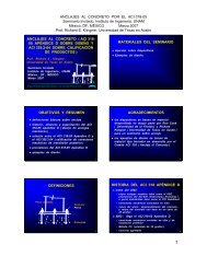
IHI – Calli<strong>de</strong> Project Results (SO2 Emissions)<br />
IFRF (APG1 Trials) – Gottelborg coal<br />
500<br />
<strong>Coal</strong>A<br />
<strong>Coal</strong>B<br />
SO2,O xy m o<strong>de</strong> (mg/MJ)<br />
400<br />
300<br />
200<br />
100<br />
<strong>Coal</strong>C<br />
0.8<br />
0.7<br />
0.6<br />
ANL-EERC Trials – Blk. Thun<strong>de</strong>r coal<br />
0<br />
0 100 200 300 400 500<br />
SO2,A ir m o <strong>de</strong> (m g/ M J )<br />
SO2 Emissio ons (lb/MMBtu)<br />
0.5<br />
0.4<br />
0.3<br />
0.2<br />
EERC‐ANL (Wet RFG)<br />
0.1<br />
EERC‐ANL (Dry RFG)<br />
Air Fired Case<br />
0<br />
1.5 2 2.5 3 3.5 4<br />
[CO2 + H2O]/[O2] Molar Ratio of Comburent
Would the capture of SO2 / SO3 in the ash<br />
enhanced by lower carbon in ash<br />
Marrier and Dibbs (1974) Thermochmica Act (Vol. 8)<br />
E.ON UK Results at 26%O2<br />
49<br />
49
Emissions – SO 2<br />
© 2004 E.ON 2012 年 3 月 29 日 , E.ON UK, Page 50
Ash Related Issue<br />
Data from the trials taken by:<br />
MBEL (Doosan Babcock), Air<br />
Products, Ulster University<br />
and Naples University (1995)<br />
51
Summary SO2/SO3 and Sulphur<br />
in Ash – (1)<br />
• Capture of sulphur in ash at the furnace section is primarily due to<br />
the high temperature direct sulphation mechanism as suggested<br />
by Okazaki et. al. (2001) as shown in their experimental results.<br />
This is pretty much in agreement to the in-flame SO2<br />
measurements done by IFRF during their APG2 trials.<br />
• Okazaki et. al. suggested that this is due to promotion of capture of sulphur<br />
by CaO species and the inhibition of the <strong>de</strong>composition of CaSO4<br />
• This mechanism is further supported from the results of IVD Stuttgart (Maier<br />
et. al.) and Imperial College (Wrigley et. al.) indicating the occurrence of both<br />
carbonation and sulphation in the ash collected from oxy-coal combustion<br />
trials. This could indicate that equilibrium reactions promoting the formation<br />
of CaCO3 and CaSO4 are probably favoured (or highly enhanced) un<strong>de</strong>r CO2<br />
rich environment.<br />
• These results established the feasibility of using in-furnace SO2 reduction by<br />
using Ca(OH)2 or CaO injection.<br />
52
Summary SO2/SO3 and Sulphur<br />
in Ash – (2)<br />
• Additional sulphur capture in ash could also be<br />
promoted by increased formation of SO3.<br />
• It should be recognised that both results s from ANL-EERC Cand IVD<br />
Stuttgart confirms that SO3 formation is higher (about 4-5 times – in<br />
terms of mass SO3 emissions per unit energy input) as compared to<br />
air fired case. However, it is not yet clear if level of recycled SO2 has<br />
it impact to the level of SO3 formation.<br />
• Capture of sulphur by this mechanism would occur along the flue gas<br />
path (during the convective section) as shown in the results by IVD-<br />
Stuttgart.<br />
o Furthermore, IVD-Stuttgart results indicated that the higher the level of SO2 are<br />
recycled , the capture efficiency of sulphur in ash is more efficient.<br />
o Nonetheless, it should be noted that that this observation in sulphur capture<br />
efficiency is coal <strong>de</strong>pen<strong>de</strong>nt.<br />
53
Summary SO2/SO3 and Sulphur<br />
in Ash – (3)<br />
• Results from Marrier and Dibbs (1974) further support the observations<br />
ma<strong>de</strong> by IVD Sttuttgart:<br />
• maximum conversion of SO2 to SO3 would occur around 700-800 o C.<br />
• Capture of sulphur in ash could be <strong>de</strong>pen<strong>de</strong>nt on the concentration of CaO and MgO<br />
in the ash. (This could probably be one of the reasons why capture efficiency of<br />
sulphur becomes coal <strong>de</strong>pen<strong>de</strong>nt)<br />
• Iron oxi<strong>de</strong>s could enhanced the formation of SO3 therefore promoting the capture of<br />
sulphur in the ash at the convective section. (This could probably be one of the<br />
reasons why capture efficiency of sulphur becomes coal <strong>de</strong>pen<strong>de</strong>nt).<br />
• Carbon in ash could diminish the efficiency in the capture of sulphur in ash. This is<br />
supported by various studies indicating a lower carbon in ash during oxy-coal<br />
combustion trials (IHI, IFRF, ANL-EERC) showed a lower SO2 emissions (i.e. higher<br />
<strong>de</strong>gree of sulphur capture in ash). A higher carbon in ash by E.ON UK experimental<br />
results indicated a nearly similar SO2 emissions to the air fired case.<br />
• Higher ash <strong>de</strong>position rate un<strong>de</strong>r the wet RFG trials could also promote<br />
higher sulphur capture in the convective section. This should be further<br />
validated!<br />
54
SO3 Emissions<br />
(Results from ANL-EERC, IVD Stuttgart, Calli<strong>de</strong>/IHI)<br />
SO3 Concentra ation (ppm m)<br />
20<br />
18<br />
16<br />
14<br />
12<br />
10<br />
8<br />
6<br />
4<br />
ANL ‐ Air<br />
IVD Stuttgart ‐ Air<br />
Calli<strong>de</strong> IHI ‐ <strong>Coal</strong> A ‐ Air<br />
Calli<strong>de</strong> IHI ‐ <strong>Coal</strong> B ‐ Air<br />
ANL ‐ <strong>Oxy</strong><br />
IVD Stuttgart ‐ <strong>Oxy</strong><br />
Calli<strong>de</strong> IHI ‐ <strong>Coal</strong> A ‐ <strong>Oxy</strong><br />
Calli<strong>de</strong> IHI ‐ <strong>Coal</strong> B ‐ <strong>Oxy</strong><br />
2<br />
0<br />
0 250 500 750 1000 1250 1500 1750 2000 2250<br />
SO2 Concentration ti (ppm)<br />
55
My Background Analysis…<br />
• SO2 to SO3 conversion will most likely to occur at the convective<br />
section…<br />
Marrier and Dibbs (1974) Thermochmica Act (Vol. 8)<br />
56<br />
56
Similar SO 3 Conversion Rate As Air Firing -<br />
Economizer Outlet Measurements in BSF<br />
Illinois Bituminous<br />
Economizer Outlet t SO 3 results<br />
North Dakota<br />
Economizer Outlet t SO 3 results<br />
SO3 ppm mv<br />
300<br />
250<br />
200<br />
150<br />
100<br />
50<br />
Air<br />
<strong>Oxy</strong> w/o SOx control<br />
<strong>Oxy</strong> w/SOx control<br />
3%<br />
2%<br />
1% Conversion<br />
SO3 ppmv<br />
100<br />
75<br />
50<br />
25<br />
Alstom 15MW th BSF<br />
Lignite SO 3 Testing - Economizer Outlet<br />
Air<br />
<strong>Oxy</strong> w/o SOx control<br />
<strong>Oxy</strong> hot FGR<br />
<strong>Oxy</strong> w/SO3 spike<br />
3%<br />
2%<br />
1% Conversion<br />
0<br />
0 5,000 10,000 15,000<br />
SO2 ppmv<br />
0<br />
0 500 1,000 1,500 2,000 2,500 3,000 3,500<br />
SO 2 ppmv<br />
Similar SO2 to SO3 conversion rates<br />
© ALSTOM 2011. All rights reserved. Information contained in this document is indicative only. No representation or warranty is given or should be relied on that it is complete or correct or will apply to any<br />
particular project. This will <strong>de</strong>pend on the technical and commercial circumstances. It is provi<strong>de</strong>d without liability and is subject to change without notice. Reproduction, use or disclosure to third parties, without<br />
express written authority, is strictly prohibited.
Burner Development for <strong>Oxy</strong>fuel<br />
<strong>Combustion</strong><br />
• Burners are critical to combustion, emissions,<br />
and thermal efficiency / capacity of the utility<br />
boilers<br />
• Critical importance to burner <strong>de</strong>velopment is a<br />
full scale testing<br />
• This is an important exercise to establish reference data<br />
that could be used in the <strong>de</strong>velopment and validation of<br />
different mo<strong><strong>de</strong>l</strong>ing tools.<br />
• This is also to gain experience in operating full scale<br />
burner. (i.e. start up/shut down, flame stability, efficiency,<br />
heat transfer, fouling and slagging, etc…).<br />
58<br />
58
Burner Development for <strong>Oxy</strong>fuel<br />
<strong>Combustion</strong><br />
• Development of Full Scale Burner Testing<br />
Programme could either be accomplished by:<br />
• Retrofitting of Full Scale Burner Test Rigs<br />
o B&W’s 30MWth CEDF Facility (Ohio, USA)<br />
o Doosan Babcock’s 40MWth MBTF Facility (Renfrew, Scotland)<br />
o Alstom ‘s 15MWth BSF Facility (Connecticut, USA)<br />
• Testing in a Full Chain <strong>Oxy</strong>fuel CCS Pilot / Demo Plant<br />
o Vattenfall’s Schwarze Pumpe Pilot Plant (Cottbus, Germany)<br />
o CS Energy’s Calli<strong>de</strong> Power Plant (Queensland, Australia)<br />
o TOTAL’s Lacq Facility (Lacq, France)<br />
o CIUDEN Demo Facility (El Bierzo, Spain)<br />
59
Today... There are 3 Major Full Scale<br />
PC Burner Testing Facilities Worldwi<strong>de</strong> Retrofitted for <strong>Oxy</strong>fuel<br />
• Babcock and Wilcox (B&W) • Doosan Babcock – • Alstom Power Plant Lab. –<br />
30MWth CEDF<br />
• Barberton, Ohio, USA<br />
• Start of Operation: Oct. 2008<br />
40MWth in 90MWth MBTF<br />
• Renfrew, Scotland, UK<br />
• Start of Operation: Jun. 2009<br />
15MWth in 30MWth BSF<br />
• Windsor, Connecticut, USA<br />
• Start of Operation: Nov. 2009<br />
• Wall Fired Burner<br />
• Wall Fired Burner<br />
• T-Fired Burner Development<br />
Development<br />
Development<br />
Courtesy of Alstom, B&W and Doosan Babcock<br />
60<br />
60
<strong>Oxy</strong><strong>Coal</strong> 2 Demonstration of an <strong>Oxy</strong>fuel <strong>Combustion</strong> System<br />
Officially opened on 24 th July 2009 Doosan Power Systems’ 40MW th <strong>Oxy</strong><strong>Coal</strong><br />
<strong>de</strong>monstration became the world’s largest <strong>de</strong>monstration of an oxyfuel combustion<br />
system.<br />
61<br />
14 September 2011 | D W Sturgeon
<strong>Oxy</strong><strong>Coal</strong> 2 Demonstration of an <strong>Oxy</strong>fuel <strong>Combustion</strong> System<br />
Safe and smooth transitions between air and oxyfuel operation were <strong>de</strong>monstrated,<br />
with realistic CO 2 levels achieved (in excess of 75% v/v dry, and up to 85% v/v dry).<br />
Oil<br />
Air Firing<br />
i<br />
(TFGR,<br />
PA, SA)<br />
Secondary<br />
Air to<br />
Secondary<br />
Flue Gas<br />
Recycle<br />
Transition<br />
Oil<br />
Air/<strong>Oxy</strong>fuel<br />
Firing<br />
(TFGR,<br />
PA, SFGR)<br />
Oil/<strong>Coal</strong><br />
Air/<strong>Oxy</strong>fuel<br />
Firing<br />
(TFGR,<br />
PA, SFGR)<br />
<strong>Coal</strong><br />
Air/<strong>Oxy</strong>fuel<br />
Firing<br />
(TFGR,<br />
PA,<br />
SFGR)<br />
Primary Air<br />
to Primary<br />
Flue Gas<br />
Recycle<br />
Transition<br />
<strong>Coal</strong><br />
<strong>Oxy</strong>fuel<br />
Firing<br />
(TFGR,<br />
PFGR,<br />
SFGR)<br />
62<br />
14 September 2011 | D W Sturgeon
<strong>Oxy</strong><strong>Coal</strong> 2 Demonstration of an <strong>Oxy</strong>fuel <strong>Combustion</strong> System<br />
40MW th <strong>Oxy</strong><strong>Coal</strong> burner turndown proven from 100% load to 40% load.<br />
40MW t<br />
32MW t<br />
24MW t<br />
16MW t<br />
20MW t<br />
• Stable rooted flame maintained for all<br />
loads down to 40% with coal ignition<br />
within the burner throat/quarl.<br />
• Comparable turndown to Doosan<br />
Power Systems’ commercially<br />
available air firing low NO X axial swirl<br />
burners.<br />
14 September 2011 | D W Sturgeon<br />
63
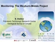
View on <strong>Oxy</strong>fuel Pilot Plant<br />
64 | Lars Strömberg, IEAGHG OCC2 Australia | 2011.09.12
Results until May 2011<br />
Operating hours 14.200<br />
Captured amount of CO2 11.500 t<br />
CO 2 -removal rate > 93 %<br />
CO 2 - purity > 99.7 %<br />
• Stable oxyfuel operation<br />
• All emission and safety values contained<br />
• Interaction between all plant components<br />
and subsystems validated<br />
• Over 50 tests t with Boiler, ASU, CO2 plant<br />
and all other components<br />
• Plant availability very high<br />
• Integration of a "cold DeNOx"<br />
4 different burners tested<br />
New tail end concepts commissioned<br />
with good results<br />
65 | Lars Strömberg, IEAGHG OCC2 Australia | 2011.09.12
Boiler and Burner<br />
• Till now three burners tested (Jet-/spin-, pure spin burner)<br />
• Igniting burner in main burner integrates<br />
• Variable spinn during operation necessary<br />
Results:<br />
• Good ignition behavior<br />
• High flame stability<br />
• Emission values are kept for certain<br />
Alstom-Burner Typ A and Typ B<br />
1<br />
Oxidantquerschnitt 1<br />
3<br />
Oxidantquerschnitt 2<br />
1<br />
2<br />
5 6<br />
4<br />
3<br />
Drall<br />
1<br />
5 6<br />
2<br />
4<br />
3<br />
Drall<br />
Drall<br />
2<br />
4<br />
5<br />
Oxidantquerschnitt 3<br />
Stauring<br />
Staub- / För<strong>de</strong>rgas-<br />
Querschnitt<br />
HPE DS®-T Burner<br />
6<br />
Kernoxidant Querschnitt<br />
Quelle: ALSTOM<br />
66 | 2OCC, U.Burchhardt | 2011-09-13
Boiler (furnace) - Temperature Comparison (Front View)<br />
<strong>Oxy</strong> 24% <strong>Oxy</strong> 28% <strong>Oxy</strong> 32% <strong>Oxy</strong> 36% Air (21%)<br />
• The gas temperatures increases with increased O2 in oxidant as expected<br />
• The temperature levels for air case corresponds to OXY28<br />
67 | 2OCC, U.Burchhardt | 2011-09-13
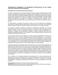
30 MW th <strong>Oxy</strong>-<strong>Combustion</strong> Pilot Plant<br />
Burner Design Type A and B<br />
Burner Type A<br />
Burner Type B<br />
<strong>Oxy</strong>-<strong>Combustion</strong> Testing in 30MWth Pilot Plant Schwarze Pumpe - IEA-OCC2 Yeppoon, Australia - Frank Kluger - 14 Sep 2011 - P 68<br />
© ALSTOM 2011. All rights reserved. Information contained in this document is indicative only. No representation or warranty is given or should be relied on that it is complete or correct or will apply to any<br />
particular project. This will <strong>de</strong>pend on the technical and commercial circumstances. It is provi<strong>de</strong>d without liability and is subject to change without notice. Reproduction, use or disclosure to third parties, without<br />
express written authority, is strictly prohibited.
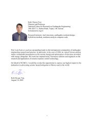
DST Burner<br />
for indirect firing<br />
‣ Hours installed:<br />
‣ <strong>Oxy</strong>fuel operation:<br />
‣ Air operation:<br />
10.200 h (19 th of April – 16 th of June)<br />
4.760 h<br />
1.250 h<br />
2nd International <strong>Oxy</strong>fuel <strong>Combustion</strong> Conference, 12th-16th September 2011, Yeppoon, Australia © Hitachi Power Europe GmbH 69
DST burner<br />
2nd International <strong>Oxy</strong>fuel <strong>Combustion</strong> Conference, 12th-16th September 2011, Yeppoon, Australia © Hitachi Power Europe GmbH 70
Premixed / hybrid mo<strong>de</strong><br />
Premixed mo<strong>de</strong><br />
DST burner<br />
Hybrid mo<strong>de</strong><br />
DST burner<br />
M<br />
M<br />
M<br />
M<br />
M<br />
M<br />
Flue gas<br />
Flue gas + O 2<br />
Flue gas<br />
M<br />
O 2<br />
O<br />
O 2 71<br />
O 2<br />
M<br />
O 2<br />
M<br />
2nd International <strong>Oxy</strong>fuel <strong>Combustion</strong> Conference, 12th-16th September 2011, Yeppoon, Australia<br />
© Hitachi Power Europe GmbH
<strong>Oxy</strong>fuel operation - <strong>Oxy</strong>fuel flame example<br />
Heat input: 27 MW th<br />
O 2 in oxydant: 32 % by vol. (wet)<br />
NO x : 416 mg/m³ = 013 0.13 kg/MWh<br />
2nd International <strong>Oxy</strong>fuel <strong>Combustion</strong> Conference, 12th-16th September 2011, Yeppoon, Australia © Hitachi Power Europe GmbH 72
CS Energy/IHI Burner Testing Programme at<br />
Calli<strong>de</strong> A Power Stationti<br />
• Calli<strong>de</strong> A Project – would<br />
be the world’s 1 st oxyfuel<br />
retrofitted power station.<br />
• First oxyfuel pilot plant that<br />
will actually produce<br />
electricity.<br />
• Installation ti of 2 new Wall<br />
Fired Burners<br />
• A unique position to provi<strong>de</strong><br />
information related to the<br />
burner – burner interaction<br />
Courtesy of CS Energy, IHI<br />
73<br />
73
Thank you<br />
• Email:<br />
• Website:<br />
stanley.santos@ieaghg.org<br />
http://www.ieaghg.org<br />
74