Mini-MCA - Users Manual - Tetracam
Mini-MCA - Users Manual - Tetracam
Mini-MCA - Users Manual - Tetracam

Create successful ePaper yourself
Turn your PDF publications into a flip-book with our unique Google optimized e-Paper software.
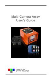
Multiple Camera Array<br />
User's Guide<br />
<strong>Tetracam</strong> Inc 21601<br />
Devonshire Street Suite 310<br />
Chatsworth,CA 91311 USA
Notices<br />
Documentation Copyright 2011 <strong>Tetracam</strong> Inc. All rights reserved.<br />
Camera software Copyright 2000-2011 <strong>Tetracam</strong> Inc.<br />
Printed in the United States of America.<br />
Specifications subject to change.<br />
This software and documentation are copyrighted materials. The making of<br />
unauthorized copies is prohibited by law. No part of the software or<br />
documentation may be reproduced, transmitted, transcribed, stored in a<br />
retrieval system or translated into any human or computer language without<br />
the prior written permission of <strong>Tetracam</strong>, Inc.<br />
Unless otherwise provided by written agreement with <strong>Tetracam</strong> Inc., this<br />
publication is provided “as is” without warranty of any kind, expressed or<br />
implied, including, but not limited to, the implied warranties of merchantability<br />
or fitness for a particular purpose. Some states do not allow disclaimer of<br />
expressed or implied warranties in certain transactions, so this statement<br />
may not apply to you.<br />
While reasonable efforts have been made to assure the accuracy of this<br />
document, in no event will <strong>Tetracam</strong> be liable for direct, indirect, special,<br />
incidental, or consequential damages resulting from any defect in this<br />
publication or the associated software. <strong>Tetracam</strong> Inc. reserves the right to<br />
change this document at any time without obligation to notify anyone.<br />
Trademarks<br />
Windows is a registered trademark of Microsoft Corporation.<br />
Photoshop is a registered trademark of Adobe Systems.<br />
Other brand or product names are trademarks of their respective holders.<br />
Version 2.3 - Last Modified April 2011<br />
<strong>Tetracam</strong> Inc 21601<br />
Devonshire Street Suite 310<br />
Chatsworth,CA 91311 USA
Table of Contents<br />
NOTICES ....................................................................................................... 1<br />
TRADEMARKS ................................................................................................ 1<br />
ABOUT THIS GUIDE ........................................................................................ 2<br />
QUICK START INSTRUCTIONS .......................................................................... 3<br />
UNPACKING THE BOX..................................................................................... 4<br />
GETTING STARTED ........................................................................................ 5<br />
Overview of the <strong>MCA</strong> System ................................................................. 5<br />
PC System Requirements ...................................................................... 6<br />
Software Installation ............................................................................... 6<br />
Hardware Installation .............................................................................. 7<br />
Camera Interconnections ........................................................................ 8<br />
<strong>MCA</strong> Optics and Filters ........................................................................... 8<br />
CMOS Sensor Relative Sensitivity .......................................................... 8<br />
The Calibration Image ............................................................................ 9<br />
Compact Flash Cards ............................................................................. 9<br />
Camera Controller ................................................................................ 10<br />
Controlling the Viewfinder ..................................................................... 10<br />
THE CAMERA VIEWFINDER ............................................................................ 11<br />
THE CAMERA MENU SYSTEM ........................................................................ 12<br />
CONTINUOUS CAPTURE MODE ...................................................................... 15<br />
CHOOSING AN IMAGE FORMAT ...................................................................... 16<br />
GPS OPTION INSTALLATION AND USE............................................................ 17<br />
EVENT LOG FILE .......................................................................................... 18<br />
HOST SOFTWARE ........................................................................................ 20<br />
PixelWrench2........................................................................................ 20<br />
SensorLink ............................................................................................ 20<br />
Connecting The Camera For Driver Installation .................................... 20<br />
USB Disk Configuration: ....................................................................... 21<br />
Managing and Processing <strong>MCA</strong> Images in PixelWrench2 .................... 21<br />
Configuring the Camera with Pixelwrench2 .......................................... 22<br />
THE 16-PIN MULTI I/O CONNECTOR .............................................................. 23<br />
MOUNTING THE UNIT .................................................................................... 23<br />
CAPTURE DELAYS FOR AERIAL PHOTOGRAPHY ............................................... 24<br />
PROGRAMMERS REFERENCE – FILE FORMATS ............................................... 25<br />
PROGRAMMER’S REFERENCE – C AND VISUAL BASIC SUPPORT ....................... 26<br />
TETRACAM RS232 SERIAL CONTROL COMMANDS .......................................... 30<br />
SUPPORT INFO ............................................................................................ 30<br />
SPECIFICATIONS .......................................................................................... 31<br />
<strong>Mini</strong> <strong>MCA</strong>-6 Dimensions ....................................................................... 32<br />
<strong>Mini</strong> <strong>MCA</strong>-12 Dimensions ..................................................................... 33<br />
Std <strong>MCA</strong>-4 Dimensions ........................................................................ 34<br />
Std <strong>MCA</strong>-6 Dimensions ........................................................................ 35<br />
INDEX ......................................................................................................... 36<br />
Multi-Camera Array User's Guide<br />
Page 1
About This Guide<br />
The Multi-Camera Array User’s Guide contains general information about the<br />
<strong>MCA</strong> products covering installation, operation, options and accessories,<br />
warranties, and technical support. The information is specific to firmware<br />
version 5.141 and later – users with earlier firmware should upgrade so that<br />
their units conform to the information herein.<br />
The <strong>MCA</strong> consists of four to twelve digital cameras organized in an array,<br />
with discrete filters installed in front of each camera in the array. The primary<br />
use of this product is to capture spectroscopic signatures of vegetation,<br />
chemicals and geology using a set of filters tailored to the targeted<br />
substance.<br />
The purpose of this document is:<br />
1. To guide the user through the installation of the product and its<br />
supporting software on its target host system.<br />
2. To describe the basic camera operating procedures.<br />
3. To describe the interaction between the camera’s interface software and<br />
the image editing and archiving software it may be used with.<br />
This document assumes that the user is very familiar with the operation of an<br />
IBM compatible personal computer running the Windows Vista, or Windows<br />
XP operating system. He should be familiar with the use of USB serial ports<br />
and USB disk devices, and in the use of spectroscopic signatures to identify<br />
materials of interest.<br />
A PDF version of this manual is supplied on the installation CD.<br />
Page 2<br />
Multi-Camera Array User's Guide
Quick Start Instructions<br />
Connect the unit to DC power source (The <strong>MCA</strong> cameras will accept power<br />
input between 12 and 14 VDC, and are suitable for most vehicle power<br />
supplies)<br />
Install PixelWrench2 before connecting the camera to the computer. This<br />
program is needed to manage connections to the camera and to extract<br />
useful data from the sets of visible light and NIR images the camera captures.<br />
With the Control Box accessory and a video display, you can review pictures<br />
in the master camera. Press the SELECT button and a menu should appear.<br />
Select items in the menu using the UP, DOWN and SELECT buttons. These<br />
buttons allow you to scroll through the selections. Pressing the SELECT<br />
button activates a selection. The REVIEW selection gives you access to<br />
images in the camera and displays them on the video Display.<br />
To view your pictures on a computer, you may remove the CF cards and<br />
install them in a CF card reader, or plug the camera into the USB interface on<br />
your computer.<br />
When plugging the camera into a computer’s USB port, Windows will<br />
recognize the camera as either an Imaging Device or a USB Mass Storage<br />
Device. You can toggle how Windows recognizes the device from the<br />
camera’s menu or by holding the SELECT button for 5 seconds while<br />
powering on the camera. To use the camera with PixelWrench2, the camera<br />
must be connected as an Imaging Device. USB Mass Storage Device mode<br />
is better suited for simple file transfers between the CF cards and Windows. If<br />
the camera is in USB Storage Device mode, “USB DISK” will appear in the<br />
viewfinder on a connected display.<br />
From PixelWrench2, you may open previews of the images on the CF card in<br />
the camera, and extract them for viewing and analysis. Consult the online<br />
manual for PixelWrench2 and the camera for more detailed instructions.<br />
When you are done with the camera, turn it off by disconnecting the power.<br />
Multi-Camera Array User's Guide<br />
Page 3
Unpacking The Box<br />
This is what you should find in the box.<br />
A Hardened Plastic Camera Case<br />
An <strong>MCA</strong> or <strong>Mini</strong><strong>MCA</strong> Digital Still Camera<br />
A CDROM with the installation software supporting the camera<br />
Product and Accessory Documentation<br />
A USB interconnection cable<br />
Compact Flash Memory Cards for each camera in the array<br />
An AC Power Adapter and Power input cable<br />
A White Teflon Calibration Plate<br />
Your camera comes with a one-year warranty against defects. You should<br />
send in the warranty card to register the camera and qualify for additional<br />
software and firmware updates.<br />
Documentation<br />
Teflon Calibration<br />
Plate<br />
Power Adapters<br />
Installation<br />
Software CD<br />
USB Cable<br />
<strong>Mini</strong><strong>MCA</strong> Digital<br />
Still Camera<br />
Power input cable<br />
Figure 1 - Contents of the Shipping Box<br />
Control Cable<br />
Cards<br />
.<br />
Page 4<br />
Multi-Camera Array User's Guide
Getting Started<br />
Overview of the <strong>MCA</strong> System<br />
The <strong>MCA</strong> imaging system consists of a set of digital still cameras compactly<br />
packaged and synchronized so they can all take pictures at the same time<br />
with only small translation errors between images from unit to unit. These<br />
translation errors are automatically corrected by the software supplied with<br />
the unit.<br />
One of the cameras in the system is set up as the MASTER camera – the<br />
master camera is responsible for synchronizing the other cameras (SLAVES),<br />
calculating exposure requirements, and logging GPS geo-referencing<br />
information.<br />
A control connector (and control box accessory) is provided to allow the<br />
camera to be triggered in flight, and to provide connection to an external GPS<br />
receiver. The control connector also has an output video signal that can be<br />
used to monitor the framing of the image. Monitoring can take place remotely,<br />
using a commonly available video transmitter for RC aircraft, or locally, in a<br />
manned aircraft, using a video monitor.<br />
Each camera has its own file system for saving images. In a six-camera<br />
6 Channel <strong>Mini</strong> <strong>MCA</strong><br />
Lens / filter layout<br />
USB Connector<br />
system there will be six compact flash cards installed in the unit. Each will<br />
have a unique volume ID and naming convention for images that allows the<br />
sets of pictures to be separated on the host PC. The software supplied with<br />
the camera automatically combines the images into multi-channel TIFF image<br />
file for convenient extraction of the data at any time.<br />
Each camera has its own band pass filter – typically a spectroscope filter<br />
commercially available from companies like Andover or Sigma. A wide variety<br />
of pass filters are available. Bandwidths of 10 nanometers and above will<br />
Multi-Camera Array User's Guide<br />
Page 5
supply acceptable images. Narrower band pass filters (less than 10 nm) can<br />
produce some artifacts in the images which must be corrected on the host<br />
PC. Band pass filters may be anywhere in the range of 400 nm (blue) to 950<br />
nm (near infrared). The spectral response graph later in this document shows<br />
the working range of the sensors. A set<br />
of six filters is ordinarily specified at the<br />
time of purchase.<br />
Images can be transferred to a host<br />
PC by removing and reading the<br />
memory cards, or by plugging in a<br />
USB cable to the USB Hub controller<br />
built into the unit. In a six-channel unit,<br />
six separate devices will appear when<br />
the unit is connected.<br />
PC System Requirements<br />
Any IBM-compatible personal computer with a free USB serial jack can be<br />
used to operate and configure the Camera. The unit produces sets of images<br />
synchronized for simultaneous capture. The images from the set can be<br />
displayed three channels at a time using RGB format for false color rendition.<br />
Each RGB rendering is about 3.9 Megabytes. You should select a computer<br />
with resources that can support manipulation of images that are this large.<br />
Our recommendations for a minimum configuration are:<br />
1 GHz or better processor, Intel or AMD<br />
Windows 7, Vista or XP operating system<br />
512 megabytes of SDRAM<br />
24 bit color graphics adapter at 1024 x 768 or better resolution<br />
1024 x 768 or higher display<br />
Large hard disk drive with 10 GB or more free space<br />
Software Installation<br />
The software installation CD contains PixelWrench2, the USB stream driver<br />
and a PDF version of the user’s manual. To install PW2, run the file<br />
Setup.exe located in the PW2 folder. The root folder of the CD also contains<br />
the image alignment file for your particular camera. Its name is<br />
xxxxxx_global.<strong>MCA</strong> where xxxxxx represents your camera serial number.<br />
If you have not previously used a digital camera on your system, the<br />
Windows operating system may need to install some additional files to<br />
Page 6<br />
Multi-Camera Array User's Guide
support the camera drivers.<br />
If your computer does not have the Microsoft .NET 3.5 framework installed,<br />
the PixelWrench2 installer will try to open Microsoft.com and download a file<br />
called dotNetfx.exe. This is the installer for .NET 3.5. This file is also on the<br />
CD in the root directory where you can run it directly prior to installing<br />
PixelWrench2.<br />
Hardware Installation<br />
The <strong>MCA</strong> and <strong>Mini</strong> <strong>MCA</strong><br />
run nominally on 12VDC<br />
external power. The<br />
input has been designed<br />
for vehicle electrical<br />
systems and can handle<br />
input voltages as high as<br />
14 volts. The power<br />
connectors are center<br />
positive.<br />
The <strong>MCA</strong> and <strong>Mini</strong> <strong>MCA</strong><br />
differ primarily in their<br />
optical capabilities and weight. The older <strong>MCA</strong> product supports replaceable<br />
C-Mount lenses with variable aperture controls to match filter characteristics.<br />
The mini <strong>MCA</strong> is designed for UAV applications, and weighs only 25% the<br />
original <strong>MCA</strong> weight. It uses smaller miniature lenses with fixed apertures.<br />
Filter characteristics are calibrated into the camera firmware in the mini <strong>MCA</strong>.<br />
The optics on the standard <strong>MCA</strong> are better suited to very narrow band pass<br />
filters.<br />
The <strong>MCA</strong> camera has a variety of connectors, as<br />
shown in the illustrations. The mini <strong>MCA</strong> has<br />
only a power connector and multifunction control<br />
connector available on the external case. All of<br />
the signals on separate connectors, including<br />
power are available on the multifunction<br />
connector. In the discussion of interconnection<br />
signals that follows, the signals may be found on<br />
the multifunction connector, and also in the case<br />
of the standard <strong>MCA</strong>, on the separate connectors<br />
provided.<br />
Power Connector<br />
Multifunction<br />
Multi-Camera Array User's Guide<br />
Page 7
Camera Interconnections<br />
Power – 12VDC center positive supply capable of delivering 0.5 Amps<br />
continuous. The supplied wall-plug type supply connects to this jack<br />
USB – The main USB I/O connector (behind access panel on <strong>Mini</strong><strong>MCA</strong>)<br />
Multi I/O – 16-pin connection to the Camera Controller for viewing video,<br />
navigating the menu, taking pictures, and connecting GPS<br />
Video Out – (Camera Controller ) NTSC or PAL video signal<br />
RS-232 – (Camera Controller ) For connecting an optional GPS receiver or<br />
sending commands to the camera. A 3.5mm stereo phone plug tip, ring and<br />
sleeve is camera receive, camera transmit, and ground, respectively.<br />
<strong>MCA</strong> Optics and Filters<br />
All channels of the <strong>MCA</strong> must be equipped with the same type of lens so the<br />
images can be merged with a minimum of error and distortion. Each channel<br />
has a receptacle for a spectrometer filter. The filters can be obtained from a<br />
commercial supplier, such as Andover. The unit is supplied with a set of six<br />
filters as specified by the customer at the time the unit is ordered.<br />
Changing filters or installing them for the first time requires that the exposure<br />
time for each channel by adjusted for the filter characteristics. In the standard<br />
<strong>MCA</strong>, the adjustment can be made by setting the apertures on the lenses, or<br />
by entering exposure constants for each channel. In the mini <strong>MCA</strong>, only the<br />
second technique is used, since the apertures in the mini <strong>MCA</strong> lenses are<br />
fixed.<br />
CMOS Sensor Relative Sensitivity<br />
The graph below shows the relative efficiency of the sensor for different<br />
bands of visible and NIR light.<br />
Page 8<br />
Multi-Camera Array User's Guide
The Calibration Image<br />
An important part of the entire camera and software system is the need to<br />
calibrate the software supplied with the camera. Calibration consists of taking<br />
an image of the Software Calibration Tile under the same lighting conditions as<br />
the images under study. This image is used to teach the application software<br />
what the spectral balance of that day's sunlight is. The ratio of red/NIR or<br />
green/NIR is then applied as an offset to the calculation of the various<br />
vegetation indices. Note: if a calibration image is not taken within an hour or<br />
two of pictures in the field, the vegetation index calculations will not be very<br />
accurate, and the pictures may not be<br />
useful.<br />
Place the Software Calibration Tile on<br />
the ground, or hold it level to ground,<br />
and photograph it. It need not fill the<br />
entire frame and it must not be<br />
overexposed. Make sure to avoid a<br />
direct reflection of the sun. The sample<br />
image on the left is of a properly<br />
exposed Software Calibration Tile.<br />
When the pictures are imported to the<br />
host computer, the calibration image<br />
will be used to refine the vegetation<br />
index calculations.<br />
Compact Flash Cards<br />
Software Calibration Tile Image<br />
The unit can handle Compact Flash (CF) cards up to 2 GB. Since stored<br />
images are about 1 megabyte each, a 512 megabyte card is the minimum<br />
capacity recommended. A set of 2 GB cards (one per channel) is supplied<br />
with the unit.<br />
Note: The unit cannot take pictures without a compact flash cards installed.<br />
We recommend that the unit's power be turned off when the compact flash<br />
card is replaced. CF cards manufactured by SanDisk have proven the most<br />
reliable in our testing of the unit.<br />
The camera is usually operated away from the host computer. If a compact<br />
flash memory reader is present on the host computer, the software can<br />
extract images directly from the card, without having to connect the camera.<br />
This allows the camera to be left in the field, or attached to a vehicle. The CF<br />
cards are exchanged to bring the pictures to a host computer.<br />
When CF cards with capacities in excess of 2 Gigabytes are used they must<br />
Multi-Camera Array User's Guide<br />
Page 9
e formatted as FAT32 cards on the PC, because the camera is not capable<br />
of initializing CF cards to FAT32 format. Care must be taken to label the<br />
volume TTCDISK[1-8], as it comes from the factory, during formatting on the<br />
PC. Also format the card using 32kb cluster (allocation unit) size for faster<br />
camera boot times. The volume information is used by PixelWrench2 to<br />
identify the device as a <strong>Tetracam</strong> camera, and identify the channels when it<br />
appears as a USB Disk. While reliable, use of very large cards with FAT32<br />
format is not recommended unless very long missions with many pictures<br />
require it.<br />
Camera Controller<br />
The camera controller is used to setup and manually control the camera. The<br />
controller has two connectors on its side: an RCA jack for video out to a TV or<br />
monitor and a 3.5mm phone jack for serial RS-232 connection to a GPS<br />
receiver. On the bottom of the controller is the 16-pin connection to the<br />
camera. At power up, a connected TV or monitor display will illuminate and<br />
begin displaying the live viewfinder image.<br />
Controlling the Viewfinder<br />
In daylight conditions, a properly set exposure will produce a fairly dim<br />
viewfinder image so that NIR data is not over-exposed. For certain pictures it<br />
may be useful to adjust the exposure using the UP and DOWN buttons.<br />
When in auto-expose mode, pressing the UP or DOWN buttons will increase<br />
or decrease the exposure by 1/6 f-stop for each press. When in fixed expose<br />
mode, pressing the UP or DOWN buttons will increase or decrease the<br />
exposure time by ½ millisecond for each press.<br />
Once the viewfinder image is satisfactory, capture can be initiated with the<br />
TAKE PIC button on the controller. The Status LED will turn from green to<br />
red, indicating that the camera is busy capturing and saving the image. After<br />
a capture, the camera completes the compression and storage of the image<br />
and the status LED returns to green indicating the camera is ready.<br />
Page 10<br />
Multi-Camera Array User's Guide
The Camera Viewfinder<br />
Once the camera is powered on, after a few moments it finishes its initial<br />
bootup sequence and enters viewfinder mode where it is ready for image<br />
captures. This is the normal ready-state of the camera. From this state, the<br />
use may adjust the exposure time up or down, using the UP or DOWN<br />
buttons, enter the menu system using the MENU / SELECT button, or<br />
capture images using the TAKE PIC button.<br />
With an external video monitor connected to the camera’s video out port, a<br />
live video image of what the camera “sees” will be shown on the screen. An<br />
overlay of information is shown on the viewfinder by default and can be<br />
turned off in the camera’s menu. Below are shown the different points of<br />
information, arranged as shown on the viewfinder screen, with descriptions<br />
for each.<br />
USB Mode – USB DISK MODE will be displayed if the camera is set to<br />
enumerate as a USB DISK when connected to a Windows computer via USB.<br />
Save Mode – Displays DCM, R8, or R10 for the type of image the camera is<br />
set to save. DCM is a compressed 10-bit format, while R8 and R10 are 8-bit<br />
and 10-bit RAW file formats, respectively.<br />
Cont. Capture – This parameter is displayed in green when Continuous<br />
Capture is enabled, and in red when capturing, and shows the amount of<br />
Continuous Capture delay set.<br />
Exposure Mode – If a FIXED EXPOSURE is set, this parameter will display<br />
the word “FIXED” in red along with the set exposure time, in milliseconds.<br />
With Fixed Exposure turned OFF, this parameter will display “AUTO A” or<br />
“AUTO P”. The “A” or “P” designation indicates the METHOD of Auto<br />
Exposure, Average or Peak. A positive or negative number may follow this<br />
parameter, indicating the Exposure Adjust setting, controlled by the UP or<br />
DOWN buttons from the viewfinder.<br />
Multi-Camera Array User's Guide<br />
Page 11
Date / Time – Date and Time is displayed.<br />
Picture Count – This parameter shows the number of images stored on the<br />
CF card.<br />
*note: SETTINGS DISPLAY in the menu controls the displaying of the above<br />
listed parameters. GPS DISPLAY and GPS HEARTBEAT in the menu<br />
controls the displaying of the parameters listed below.<br />
GPS Position – With a GPS receiver connected and communicating with the<br />
camera, position coordinates will be displayed. If the GPS receiver loses its<br />
signal lock, “WAITING FOR GPS” will be displayed in RED until it recovers its<br />
signal lock.<br />
GPS Heartbeat – This is an indicator to confirm that a connected GPS<br />
receiver is sending data to the camera. Every time the camera gets a new<br />
packet of data, the “/” character in “GPS/” will toggle back and forth, between<br />
the “\” and “/” characters.<br />
The Camera Menu System<br />
The camera can be configured from the host computer via the USB<br />
connection or by use of the menu selections accessible with the controller<br />
and video display.<br />
Operation of the menu system uses the three rightmost buttons on the<br />
controller: the SELECT, UP and DOWN buttons. To enter the menu system,<br />
the SELECT button is pressed once. Sub menus appear, or menu items<br />
which have values to the right of them.<br />
To select a submenu, use the UP/DOWN buttons to move the cursor up or<br />
down to the desired submenu entry. Press the SELECT key to display the<br />
next menu page in the tree. If a submenu is not available, (REVIEW cannot<br />
be accessed unless pictures have been taken) it will be gray in the display<br />
instead of white. The selected entry is hi-lighted in green.<br />
To change a menu item value, navigate to it by pressing the UP/DOWN<br />
buttons, and select it by pressing SELECT. The menu item’s value will turn<br />
green, indicating that it is selected. Use the UP/DOWN buttons to scroll<br />
through the available values, and SELECT again to set the value.<br />
The menu system can be exited at any time by pressing the TAKE PIC<br />
button.<br />
Page 12<br />
Multi-Camera Array User's Guide
MAIN MENU<br />
REVIEW – options for<br />
viewing or deleting<br />
stored images.<br />
INFO – view battery<br />
status, firmware version<br />
and storage card space<br />
used / free.<br />
CAPTURE METHOD –<br />
set file save mode, toggle fixed or auto exposure, toggle single or continuous<br />
capture settings, set alarm capture mode.<br />
SETUP – set video and USB mode, menu language, date / time, quickview,<br />
GPS and viewfinder, restore defaults, format memory card.<br />
DONE – Every menu page ends in a DONE selection. Selecting DONE will<br />
save any settings that exist on that page and return to the previous screen.<br />
REVIEW<br />
THUMBNAIL – displays<br />
four images at once on<br />
the screen to quickly scroll<br />
through images while<br />
viewing them.<br />
FULL SCREEN – show<br />
full size images one at a<br />
time<br />
DIRECTORY – show a list of saved images<br />
DELETE ALL – erase all images on memory card at once<br />
All images are listed in order from most recent to oldest. Images can be<br />
erased one at a time when selected individually.<br />
INFO<br />
Shows the power supply<br />
voltage, camera firmware<br />
version number, used,<br />
free, and total space on<br />
the memory card.<br />
Multi-Camera Array User's Guide<br />
Page 13
CAPTURE METHOD<br />
SAVE MODE – set the type of image file the camera saves. See “Choosing<br />
An Image Format” section for more help.<br />
FIXED EXP – select an<br />
exposure time in<br />
milliseconds or OFF for<br />
auto-exposure mode.<br />
AUTO EXP METHOD –<br />
select PEAK if the subject<br />
is the brightest part of the<br />
image, or AVERAGE for all others cases.<br />
CONT CAPTURE – select to configure Continuous Capture mode.<br />
SETUP<br />
VIDEO – sets the camera<br />
to output NTSC or<br />
various PAL standard<br />
display feeds.<br />
USB MODE – sets what<br />
the camera looks like to<br />
Windows if connected via<br />
USB. Set this to<br />
CAMERA to communicate with the camera via PixelWrench2. Set this to<br />
DISK for direct file transfers between Windows and the camera. The camera<br />
will reboot if this setting is changed.<br />
LOG EVENTS – turn this ON to capture events to a log file.<br />
DATE / TIME – Select this to set the time and date for image stamps.<br />
QUICKVIEW – select this to set the amount of time a newly captured image<br />
is displayed on the viewfinder screen.<br />
MORE… – More setup options<br />
Page 14<br />
Multi-Camera Array User's Guide
MORE…<br />
LANGUAGE – Set the<br />
menu language.<br />
GPS BAUD – Set the<br />
serial connection data<br />
rate between the camera<br />
and a GPS receiver.<br />
GPS HEARTBEAT –<br />
When ON, an indicator is shown on the viewfinder screen, signaling each<br />
time the camera receives information from the GPS receiver.<br />
GPS DISPLAY – When ON, GPS coordinates are displayed on the viewfinder<br />
screen.<br />
SETTINGS DISPLAY – Toggles the display of settings information on the<br />
viewfinder screen, such as exposure, files save type, picture count, etc.<br />
FORMAT CF CARD – select this option to re-format the CF card.<br />
RESTORE DEFAULTS –<br />
select this option to<br />
return all settings to<br />
factory defaults. This is<br />
recommended any time<br />
the camera’s firmware is<br />
upgraded.<br />
Continuous Capture Mode<br />
This mode of operation causes the camera to begin taking pictures when the<br />
TAKE PIC button is pressed, and to continue taking pictures until the button<br />
is pressed again. It is the simplest way to operate the camera on a remote<br />
aerial vehicle. The rate of capture is controlled by the file format selected, and<br />
the additional delay set between pictures.<br />
CONT CAPTURE – turns<br />
Continuous Capture<br />
mode ON or OFF<br />
Multi-Camera Array User's Guide<br />
Page 15
CONT DELAY – sets the minimum amount of delay between captures. RAW<br />
images take less than a second to save while DCM images may take about<br />
five seconds (compression), so very short delay settings (such as 5 seconds<br />
or less) may not be realized because of file save times. Range is from 0 – 60<br />
seconds.<br />
For fastest possible operation , configure the camera for SAVE MODE RAW<br />
8 and LOG EVENTS OFF.<br />
Choosing An Image Format<br />
The highest rate of capture is for the 8 Bit RAW file format, at about one<br />
picture per second. The speed depends in part on the features of the CF<br />
card. For users who require more precision, the 10 bit RAW format is the next<br />
fastest.<br />
The RAW files are quite large – 6 megabytes for the 10 bit format and 3<br />
megabytes for the 8 bit format. Compression (DCM format) cuts the size of<br />
the files in half, but takes longer to capture. We therefore think of DCM<br />
compressed continuous mode as “low speed”. Besides the smaller file size,<br />
another advantage of the DCM format is that the files contain previews which<br />
speed up the image access speed using Pixelwrench2.<br />
File<br />
Format<br />
RAW 8<br />
bit<br />
RAW 10<br />
bit<br />
DCM 10<br />
-----Advantages-----------<br />
Fastest cycle time<br />
Fastest cycle time with<br />
full dynamic range<br />
Smallest file size with full<br />
dynamic range<br />
----------Disadvantages---------<br />
Less dynamic range, no embedded<br />
previews<br />
Big files, no embedded previews<br />
Longest time between pictures (up<br />
to 5 seconds)<br />
The table above shows the relative advantages and disadvantages of camera<br />
file formats. These apply to all modes of operation.<br />
Page 16<br />
Multi-Camera Array User's Guide
GPS Option Installation and Use<br />
Your <strong>MCA</strong> will capture and append the most recent GPS data string to each<br />
image as it is taken. The following requirements apply; Your GPS receiver<br />
must be configured to output the standard NMEA RMC and/or GGA<br />
sentences. The default output protocol for NMEA sentences is 4800 baud, 8<br />
data bits, 1 stop bit, no parity. Your receiver should allow you to configure it<br />
for RMC and/or GGA at 4800:8:1:N. If your GPS receiver can be configured<br />
for a higher Baud, you should take advantage of the feature, since it will<br />
make the GPS data more accurate since less time would be lost transferring<br />
the messages. The menu in the camera has an entry for the GPS Baud.<br />
There is also an advanced setup screen, accessible via Pixelwrench2 that<br />
save a higher baud rate.<br />
The GGA sentence is emitted once per second and contains the following<br />
fields:<br />
1. Time UTC<br />
2. Latitude and Longitude<br />
3. Fix quality<br />
4. Number of satellites tracked<br />
5. Horizontal dilution of position<br />
6. Altitude in meters MS<br />
7. Height above MSL<br />
Attach the optional serial cable to the small serial connector (see the<br />
illustration in the Hardware Installation section of this manual). Attach the<br />
other end to the serial port of the receiver.<br />
The most recent GPS sentence sent to the camera will be appended to the<br />
image data file. You can view the GPS data in the image using Pixelwrench2.<br />
The camera firmware also supports an event, or position, logging system that<br />
will exactly place the GPS locations at the time pictures are taken, with a<br />
resolution of 10 milliseconds.<br />
The camera also has two features you can turn on in the setup called GPS<br />
HEARTBEAT and GPS DISPLAY, which will toggle an indicator on the<br />
viewfinder screen each time it receives a new GPS sentence and will show<br />
the last GPS position received. This is useful to see that the camera is<br />
properly receiving GPS data.<br />
Multi-Camera Array User's Guide<br />
Page 17
Event Log File<br />
When LOG EVENTS is set to ON in the CAPTURE METHOD screen, The<br />
camera will maintain a file with a record of key events that can be used to<br />
accurately position the location at which the picture was taken. Generally, a<br />
GPS receiver is connected to the camera serial port that sends $GGA… and<br />
$RMC…position strings to the camera.<br />
This feature is used most often with aerial photography, when the GPS point<br />
is directly below the camera, so that both the camera and the image are at<br />
the same coordinate.<br />
When the option is enabled, the camera creates the file CURRENT.LOG on<br />
the CF memory card in root folder. If there is a pre-existing CURRENT.LOG<br />
file, the file is moved to the image folder (TTC<strong>MCA</strong>0 in the case of the <strong>MCA</strong><br />
master camera) and renamed according to the image numbers that were<br />
captured while the camera was last in operation. Only the master camera<br />
channel logs GPS data and image events.<br />
For Example: If images 31, 32, 33, and 34 were captured, there will be event<br />
log records for each of those captures in the file. The file is scanned image<br />
capture records, and the smallest and largest image numbers found are used<br />
to compose a file name. In this case, the file would be renamed to<br />
00310034.LOG. The first four characters of the new file name are the lowest<br />
image capture record in the file; the second four letters are the highest image<br />
capture record in the file.<br />
A typical Event Log file is shown on the next page. Each line shown is one<br />
record in the file, terminated by a newline character and NULL. The NULL<br />
characters are hidden, and additional line feeds are added for clarity in the<br />
illustration.<br />
Log files are much easier to manage if the camera is set up to operate in the<br />
USB Disk mode described earlier. The Log files are not directly accessible<br />
from Pixelwrench2 using the stream interface. When the camera shows up as<br />
a folder window on the desktop, as it does in USB Disk mode, the moving<br />
and deleting files is trivial.<br />
You can use the GPS Distiller tool to manage image and GPS log files. See<br />
the PW2 help file for more information on how PW2 uses the distilled log files<br />
to refine the embedded GPS data in each image.<br />
Remember, you can switch the camera between being recognized by<br />
Windows as a USB MASS STORAGE DEVICE and an IMAGING DEVICE<br />
(USB Disk Mode vs. able to connect to PixelWrench2) by holding the<br />
SELECT button down for five seconds during power up.<br />
Page 18<br />
Multi-Camera Array User's Guide
The CLK record is added<br />
when the camera powers up.<br />
It shows the camera date and<br />
Every Record has a “Ticks” Field<br />
time.<br />
that shows the cameras internal<br />
clock count of 10 millisecond ticks.<br />
The count 104 means that che CLK<br />
record was written 1.040 seconds<br />
CLK 000000104 Date/Time: 10/22/2009 15:15:01<br />
after power on.<br />
GPS 000002006 00217 $GPRMC,192254.00,A,2942.79012,N,08223.30667,W,000.0,000.0,221009,03.3,W,A*0B<br />
GPS 000002064 00217 $GPRMC,192254.00,A,2942.79012,N,08223.30667,W,000.0,000.0,221009,03.3,W,A*0B<br />
$GPGGA,192255.00,2942.79047,N,08223.30663,W,1,04,2.58,00040,M,-031,M,,*5D<br />
IMG 000003049 00218<br />
If a GPS is connected, an entry<br />
GPS 000003102 00218 $GPRMC,192302.00,A,2942.79461,N,08223.30899,W,000.0,000.0,221009,033,W,A*06<br />
is made each time a GPS<br />
GPS 000003280 00219 $GPRMC,192302.00,A,2942.79461,N,08223.30899,W,000.0,000.0,221009,033,W,A*06<br />
update string is received.<br />
$GPGGA,192303.00,2942.79517,N,08223.30922,W,1,04,2.58,00062,M,-031,M,,*55 Different GPS messages are<br />
concatenated as they come in<br />
When a picture is taken, a record is written showing the<br />
system ticks at the end of integration. The camera can only<br />
do one thing at a time, so there will always be a system ticks<br />
offset between capturing a picture and the GPS messages.<br />
The actual position of the camera when the picture is<br />
captured can be approximated by interpolating between the<br />
two GPS messages using the system ticks.<br />
Multi-Camera Array User's Guide<br />
Page 19
Host Software<br />
The software supplied on the installation CD is made of several major<br />
components:<br />
1. An image acquisition and manipulation application, named Pixelwrench2<br />
2. An optional GPS guided camera trigger application named SensorLink<br />
3. A camera interface DLL for extracting images from the camera or CF<br />
card, and converting them to Windows DIB format for display.<br />
The goal of this software is to allow the user to extract the Blue/ Green /Red<br />
false color images from the captured image set so that band radiation can be<br />
visibly displayed regardless of where in the spectrum (NIR / visible) it may lie.<br />
PixelWrench2<br />
PixelWrench2 (PW2) is a powerful image editing program with several tools<br />
specific to multi-spectral images and working with <strong>Tetracam</strong> ADC and <strong>MCA</strong><br />
cameras. Open the PW2 folder and run Setup.Exe. This will install<br />
PixelWrench2. See the PixelWrench2 online help for more information.<br />
PW2 can open <strong>MCA</strong> proprietary DCM10, RAW10 and RAW8 image files<br />
along with several standard image file types (BMP, JPEG, TIF, PNG etc.)<br />
If you purchased the optional SensorLink application you will find a folder by<br />
that name on the CDROM included with the camera.<br />
SensorLink<br />
SensorLink is a GPS waypoint triggering application enabling camera<br />
triggering at pre-defined waypoints. It uses the same .NET 2.0 framework.<br />
Simply run Setup.exe in the SensorLink folder to install it. See the SensorLink<br />
online help for more information.<br />
Connecting The Camera For Driver Installation<br />
With the camera powered up and USB MODE set to CAMERA, connect the<br />
USB cable from a working USB port on the computer to the connector labeled<br />
USB on the camera interconnect panel.<br />
On Windows XP systems, the first time the camera is connected to a USB<br />
port, Windows will launch the New Hardware Found wizard. This will guide<br />
you through installation of the camera driver called SvStream.sys. If you plan<br />
to operate the camera as a USB Disk, skip to the next section.<br />
Do not let Windows search for the driver. In every case select the option<br />
where you specify the name and location of the driver. The driver<br />
SvStream.sys and its information file SvStream.inf will be copied to your<br />
Windows/System32/Drivers folder when you install either PixelWrench2 or<br />
Page 20<br />
Multi-Camera Array User's Guide
SensorLink. When the driver installation wizard asks for a location, browse to<br />
Windows/System32/Drivers.<br />
In both PixelWrench2 and SensorLink, you are required to specify the camera<br />
type prior to accessing the camera. In PixelWrench2, on the Camera Toolbar,<br />
click the small down arrow on the top button (Status). Select <strong>MCA</strong> as your<br />
camera type. This loads the correct DLL for use with the <strong>MCA</strong>. See the<br />
PixelWrench2 online help file for further specifics on camera communications.<br />
USB Disk Configuration:<br />
With the introduction of firmware version 5.097 the <strong>MCA</strong> can be configured to<br />
appear as a USB disk drive to the operating system. For Windows Vista, or<br />
operating systems other than Microsoft, the camera must be operated as a<br />
USB Disk device. To toggle the USB mode between DISK and CAMERA,<br />
change the USB MODE setting in the camera’s menu SETUP page and then<br />
select DONE – the camera will reboot automatically with the new mode set.<br />
You can also toggle the USB MODE setting by simply holding down the<br />
MENU / SELECT button for a few seconds during power up.<br />
However the camera is configured, it will be recognized by Pixelwrench2<br />
when that application is started. In the original stream mode of operation,<br />
Pixelwrench2 is the only way to exchange data with the camera over a USB<br />
link. When the unit is configured as a USB Disk, files can be dragged and<br />
dropped to and from the camera from any personal computer that has USB<br />
disk drivers.<br />
Managing and Processing <strong>MCA</strong> Images in PixelWrench2<br />
The <strong>MCA</strong> system writes losslessly compressed<br />
image files or RAW files to the CF card for every<br />
image. These images carry the extension *.DCM<br />
or *.RAW. PixelWrench2 offers all the tools<br />
needed for management of <strong>MCA</strong> images located<br />
on the pages of the IndexTools form.<br />
There are four ways to retrieve images from the<br />
<strong>MCA</strong>;<br />
1. Remove the CF card from the camera and<br />
copy its contents to a folder on your computer.<br />
The *.DCM and *.RAW files can then be opened<br />
directly in PixelWrench2.<br />
2. In PixelWrench2; open the camera toolbar<br />
then click Open Camera. The camera inventory<br />
screen will appear with thumbnails of all the<br />
Multi-Camera Array User's Guide<br />
Page 21
images. Select an image (or images) then click Load. The image(s) will be<br />
extracted from the camera, color processed using the matrix values entered<br />
and stored by the DLL and displayed on screen as an RGB dib.<br />
3. Power up the camera in USB disk mode and open *.DCM or *.RAW files<br />
directly using PW2.<br />
4. Transfer all the files to the PC, and open them with Pixelwrench2 after they<br />
are on the hard disk.<br />
Configuring the Camera with Pixelwrench2<br />
Many camera configuration settings can be modified using the Edit Camera<br />
Settings dialog accessed from the PW2 Camera Toolbar. To open the Edit<br />
Camera Settings dialog, make sure the camera is powered up and connected<br />
to USB as a CAMERA (not as a DISK). Click Status:ADC to enable the other<br />
toolbar buttons. Click Setup and the Setup Camera Attributes dialog will<br />
appear. Click Advanced and the Edit Camera Settings dialog will appear.<br />
This dialog on the next page contains two columns of edit boxes. Place your<br />
cursor over an edit box to view a tooltip describing the setting parameters for<br />
that box. In the figure, the cursor was placed over the SAVE MODE box. The<br />
tooltip shows the possible settings for file save mode. This camera is<br />
configured to save in DPCM lossless. Many of the settings boxes do not<br />
apply to how the ADC should be configured and there is no reason to change<br />
the existing settings.<br />
GPS BAUD –<br />
Sets the baud<br />
rate for capture of<br />
GPS data. NMEA<br />
default is 4800<br />
but some<br />
receivers support<br />
higher rates.<br />
NTSC PAL<br />
STATE – 0 for<br />
NTSC, 1 through<br />
4 for several PAL<br />
configurations, 5<br />
to disable and<br />
use the LCD<br />
(default power up<br />
condition).<br />
Image Number<br />
Index – Sets the<br />
Page 22<br />
Multi-Camera Array User's Guide
number that will be applied to the next image taken, then auto increments as<br />
images accumulate. Can be set to any positive value or 0.<br />
SAVE MODE – Sets the file format that images are saved in. The ADC<br />
should save in DCM, RAW 10 or RAW 8 (1, 2 or 3, respectively).<br />
FIXED EXPOSURE – Allows presetting a fixed exposure. The value is<br />
entered in microseconds. Enter 0 to set the camera to Auto Exposure mode.<br />
AUTO EXPOSE – Sets the method of Auto Exposure Mode, Average or Peak<br />
The 16-Pin Multi I/O Connector<br />
The following describes the 15-pin functions of the Multi I/O connector:<br />
1 – supply power<br />
2, 3, 4 & 5 – MENU/SELECT, UP, DOWN, and TAKE PIC buttons,<br />
respectively. Momentarily short to ground for button activation.<br />
6 – power switch / external event trigger<br />
7 – RS-232 Transmit (GPS)<br />
8 – RS-232 Receive (GPS)<br />
9 – Red LED: logic high when camera is busy<br />
10 – Green LED: logic high when camera is on / idle<br />
11 – (NC)<br />
12, 13 – NTSC or PAL video signal and ground, respectively<br />
14 – 3.3 V (logic high)<br />
15 – ground<br />
16 – (NC)<br />
Mounting the unit<br />
The four ¼” holes in the top flange of the standard <strong>MCA</strong> camera housing are<br />
there to accept mounting bolts. In the case of the <strong>Mini</strong><strong>MCA</strong>, the four<br />
fasteners that attach the bottom plate to the blue case should be used. It is<br />
always advisable to provide vibration isolation between the camera and<br />
aircraft. Additionally make sure to ground the camera using to the mount. If<br />
the camera is mounted on non-conducting vibration isolators a ground strap<br />
should be provided. Dress and restrain all interconnect cables to prevent<br />
snagging or undue disturbance by prop blast etc. The <strong>MCA</strong> camera housing<br />
and optics are not weatherproof. If the camera is mounted externally, weather<br />
protection should be provided<br />
See the dimensional illustration in the Specification section for additional<br />
details.<br />
Multi-Camera Array User's Guide<br />
Page 23
Capture Delays for Aerial Photography<br />
The simplest way to map large areas is to place the camera in Continuous<br />
Capture mode with a delay that will ensure adequate overlap of the images.<br />
Since picture storage is cheap, 30 to 50% overlap is recommended. In order<br />
to calculate the delay, the cruise speed of the aircraft and altitude above the<br />
ground must be known. For example:<br />
Using the standard 8.5mm focal length lens, at 2500 feet AGL the camera<br />
captures 1/2 meter per pixel, or 1.28 kilometers along the long axis. If<br />
approximately 30% overlap is desired, we would take pictures every 450<br />
meters. If the aircraft is traveling at 180 km/hour or 50 m/sec, the time to<br />
cover 450 meters is nine seconds. We would, therefore, set the Continuous<br />
Capture delay to nine seconds or less.<br />
Increasing the altitude above the ground increases the delay needed while<br />
reducing the ground resolution of the images. At 5000 feet AGL, the camera<br />
resolution is approximately 1 pixel per meter, which is good enough for many<br />
crop surveys. At this altitude the required delay is doubled.<br />
Aircraft forward speed 180<br />
km / hr or 50 m / sec<br />
Altitude:<br />
640 meters<br />
of ground<br />
coverage<br />
2500 feet<br />
AGL<br />
The captured images can be easily assembled into a mosaic by stitching<br />
software. Autopano Pro does a fast and accurate job of building a mosaic<br />
from separate images. We recommend that the images be processed first<br />
into the color space needed for analysis - palletized NDVI, or false color NIR,<br />
for example. PixelWrench2 can do this quickly, using its built in batch<br />
function.<br />
Page 24<br />
Multi-Camera Array User's Guide
Programmers Reference – File Formats<br />
The camera uses proprietary formats for lossless data storage. DCM files are<br />
compressed using differential encoding and Huffman compression. RAW files<br />
are the array of captured pixel values with header and trailer information. The<br />
exact format of these file in 8 and 10 bit form is shown below.<br />
10 Bit Raw File Format<br />
The RAW file format contains both Header and trailer information. For values<br />
greater than 255, two bytes are used in little endian (Intel) configuration for<br />
header, trailer and pixel values.<br />
Byte 0-3 Size of raw image in bytes – 32 bit value<br />
Byte 4<br />
Bits per pixel – 10 for this format<br />
Byte 5<br />
Format tag – 16 for RAW files<br />
Bytes 6-7 Pixel Columns – 16 bit value. This is pixels not bytes<br />
Bytes 8-9 Pixel Rows – 16 bit values<br />
Bytes 10-(image size + 10) PIXEL DATA – 16 bit values<br />
Bytes (image size + 10)-(EOF - 28) GPS data. $GGA and $RMC strings<br />
Last 28 Bytes – ASCII exposure string<br />
formatted: "EXPOSURE:%08ld uSeconds\n"<br />
8 Bit Raw File Format<br />
Byte 0-3 Size of raw image in bytes – 32 bit value<br />
Byte 4<br />
Bits per pixel – 8 for this format<br />
Byte 5<br />
Format tag – 16 for RAW files<br />
Bytes 6-7 Pixel Columns – 16 bit value. This is pixels not bytes<br />
Bytes 8-9 Pixel Rows – 16 bit values<br />
Bytes 10-(image size + 10) PIXEL DATA – 8 bit values<br />
Bytes (image size + 10)-(EOF - 28) GPS data. $GGA and $RMC strings<br />
Last 28 Bytes – ASCII exposure string<br />
formatted: "EXPOSURE:%08ld uSeconds\n"<br />
10 Bit DCM File Format<br />
Byte 0-3<br />
calculate<br />
Byte 4<br />
Byte 5<br />
Size of image data, GPS data, and various tags<br />
in bytes – 32 bit value This value can be used to<br />
a pointer to the JPG preview data<br />
Bits per pixel – 10 for this format<br />
Format tag – 16 for RAW files<br />
Multi-Camera Array User's Guide<br />
Page 25
Bytes 6-7 Pixel Columns – 16 bit value. This is pixels not bytes<br />
Bytes 8-9 Pixel Rows – 16 bit values<br />
Bytes 10-(data size + 10) DATA – 8 bit values<br />
Bytes (data size+10)-EOF JPEG Preview image.<br />
Looking backwards into the data encompassed by the size value in the header there<br />
are several fixed length fields, given below with their sizes.<br />
GPS data – 1024 Bytes<br />
Tags for temperature and clock ticks – 16 bytes<br />
We do not recommend trying to process the DCM files with your own code. Contact<br />
<strong>Tetracam</strong> for assistance with sample ‘C’ source files if reading the DCM file data is<br />
absolutely necessary.<br />
Programmer’s Reference – C and Visual Basic<br />
Support<br />
The interface to the camera is in the library SXGA<strong>MCA</strong>.DLL This library<br />
provides a number of useful camera interface functions. Developers, to<br />
incorporate the camera interface into their own programs and plug-ins, can<br />
use the interface functions embedded here. The file sxga<strong>MCA</strong>.lib is provided<br />
in the installation directory to allow static linking to the DLL.<br />
The “include” file loadext.h is available in the installation directory to be made<br />
part of any C or C++ program making use of the DLL. It is reprinted in part<br />
below. All requests are made by filling the PixRequest structure before the<br />
function is called. Sample source files are available from <strong>Tetracam</strong> to help<br />
with the creation of a custom application.<br />
typedef struct _PXR<br />
{<br />
int requestType;<br />
int workSilently;<br />
int imageNumber;<br />
char far *fileName;<br />
int imageBlue;<br />
int imageGreen;<br />
char far *statusString;<br />
} PixRequest;<br />
// ACTION type<br />
// do not pop up status or hourglass the cursor<br />
// 0 = last image in camera or file<br />
// 0000:0000 = use camera - Otherwise the file to open<br />
// "" = ask userask user for file name<br />
// "xxxx" = use file xxxx.DCA for reading<br />
// Used for various arguments<br />
// Used for various arguments<br />
// copy camera/image status string to here<br />
// if not 0000:0000<br />
In Visual Basic a wrapper function is provided which accepts the values<br />
passed in as individual variables. It then creates the required structure before<br />
calling ProgrammerPlug(). A sample calling sequence from Visual Basic is<br />
shown below the interface function definition:<br />
Page 26<br />
Multi-Camera Array User's Guide
TTCAM_API HANDLE VBProgrammerPlug<br />
(<br />
int FAR *requestType,<br />
int FAR *workSilently,<br />
int FAR *imageNumber,<br />
char FAR *fileName,<br />
int FAR *imageBlue,<br />
int FAR *imageGreen,<br />
char FAR *statusString<br />
);<br />
/* Here is what a call looks like made from Visual Basic into the DLL:<br />
Declare Function VBProgrammerPlug% Lib "SXGA<strong>MCA</strong>"<br />
(<br />
requestType%,<br />
workSilently%,<br />
imageNumber%,<br />
fileName as Any,<br />
imageBlue%,<br />
imageGreen%,<br />
statusString as Any<br />
)<br />
For integers, According to the VB manual for version 1.0 or thereabouts,<br />
VB passes, by default, all arguments by reference, (or far pointers,<br />
if your a 'C' programmer. ByVal overrides this by placing the contents<br />
of the variable on the stack, rather than the pointer to the variable.<br />
For strings, It appears the ByVal is the way to point to a string that is<br />
to be modified by the DLL. The examples in the book for calling Windows<br />
APIs that modify strings show a declaration as ByVal. See the chapter<br />
headed "Calling DLL Routines with Specific Data Types" for details.<br />
To pass a NULL pointer to VBProgrammerPlug, use ByVal 0& as the<br />
parameter for fileName or statusString. To pass a pointer to a fixed length<br />
string, use the syntax ByVal StringName$ in the argument list.<br />
*/<br />
The Visual Basic call ends up here after translation of the calling parameters into a PixRequest Structure<br />
TTCAM_API HANDLE PASCAL ProgrammerPlug(PixRequest FAR *);<br />
/******* Multifunction DLL interface *********************************<br />
IMPORTANT<br />
The caller must always use the HOOKUP request before any other reqests are made!!!!<br />
Passed a pointer to a request block this function will perform the<br />
requested action, (see enumerated list, below) and return either the state<br />
of the current hookup, a handle to a DIB image, or the camera or file<br />
status string. After processing any image controlled by the DIB handle<br />
returned, you are responsible for freeing the memory controlled by the<br />
DIB's handle BEFORE calling ProgrammerPlug for another image.<br />
*/<br />
enum {HOOKUP = 0,<br />
// Hook up to the camera/file and prepare DLL to<br />
// load images in following calls.<br />
Multi-Camera Array User's Guide<br />
Page 27
if fileName = 0000:0000, use the camera<br />
// if fileName = "xxxxx" or "xxxx.xxx", use file<br />
// if fileName = "" or "*", prompt user for file name<br />
// RETURNED PixRequest values:<br />
// requestType = COLOR or GRAYSCALE<br />
// depending on camera or file type<br />
// imageNumber set to # of images available<br />
//<br />
// requestType and imageNumber are both set<br />
// to 0 if a file or camera I/O error occured<br />
// If a non-NULL pointer is found in statusString,<br />
// the camera or file status string is copied. a ""<br />
// is returned if there was an error.<br />
STAMP = 1, // return a handle to the STAMP DIB<br />
// RETURNED PixRequest values:<br />
// HANDLE to a D)evice I)ndependant B)itap, (DIB)<br />
// requestType = COLOR or GRAYSCALE depending on<br />
// what picture type the stamp represents<br />
// Returns a 0 on error<br />
GETIMAGE = 2, // standard gray scale image<br />
// RETURNED PixRequest values:<br />
// HANDLE to a DIB<br />
// Returns a 0 on error<br />
CAPTUREBUFFER = 7,<br />
// Returns the camera's image capture buffer<br />
// as a DIB. Stretch, sharpen and scale<br />
// are also done.<br />
// CALL WITH:<br />
// imageNumber = image type to return<br />
// RETURNED PixRequest values:<br />
// HANDLE to a DIB<br />
// returns NULL on error<br />
CAMERASTATUS = 8,<br />
IMAGESTATUS = 9,<br />
// Send the camera status string<br />
// RETURNS:<br />
// Camera status string copied to statusString.<br />
// Returns "" on error<br />
// Send the imageNumber status string to<br />
// RETURNS:<br />
// Image #imageNumber status copied to statuString<br />
// Returns "" on error<br />
SETEXPOSURE = 10, // Send the value in Blue (LSW) and Green (MSW)<br />
// to camera as exposure time. 0=automatic,<br />
MULTISELECT = 16, // Allow Operator to Selecting Multiple Images<br />
// CALL WITH:<br />
// imageNumber = Number of images pre-selected<br />
// statusString= pointer to NULL terminated byte<br />
Page 28<br />
Multi-Camera Array User's Guide
SNAPSHOT = 17,<br />
FASTSHOT = 18,<br />
// array containing the ID numbers of<br />
// images to pre-select, in the order<br />
// desired.<br />
// ARRAY SPACE MUST BE AT LEAST<br />
// 57 BYTES!!<br />
// imageGreen = Maximum number of images allowed<br />
// to be selected. If 0, the max<br />
// is the number of images in the<br />
// file/camera.<br />
// imageBlue = TRUE=Show selection order number<br />
// in stamp upper left corner.<br />
// FALSE= No selection Number.<br />
// RETURNED PixRequest values:<br />
// imageNumber = Number of images selected, or<br />
// zero if none or error<br />
// statusString= pointer to NULL terminated byte<br />
// array containing the ID numbers of<br />
// operator selected images in the<br />
// order selected. The array is<br />
// left untouched by errors.<br />
// Take a picture<br />
// CALL WITH:<br />
// Nothing<br />
// RETURNED PixRequest values:<br />
// imageNumber = TRUE if connection made<br />
// FALSE if comm I/O error<br />
// Take a fast snapshot, and return the DIB<br />
// CALL WITH:<br />
// imageGreen = Non-zero uses an on-screen Viewfinder<br />
GETCOMPRESSEDDATA = 19,<br />
ERASEIMAGES = 22,<br />
// Return DIB HANDLE points to the<br />
//compressed JPEG or DPCM<br />
// Data from the file in the camera.<br />
// Erases all images in the camera<br />
// without prompting the user for confirmation.<br />
};<br />
CLOSECAMERAPORT = 25, // Shuts down communications thru any currently<br />
// active port<br />
Multi-Camera Array User's Guide<br />
Page 29
<strong>Tetracam</strong> RS232 Serial Control Commands<br />
Camera serial port command strings consist of a lead-in character (ESC), a<br />
command character (A – Z, a - z), and a number of numeric arguments. The<br />
numeric arguments are strings of Hex Ascii digits either 4 or 8 characters<br />
long depending on the magnitude of the value (16 bit or 32 bit). Separators<br />
are not required between the argument values, or between the command<br />
character and an argument. Spaces can be used as separators if desired.<br />
Below is a table of the command characters currently implemented, and a<br />
description of the responses to be expected from the camera. Arguments are<br />
shown as or depending on their magnitude (16 or 32<br />
bits).<br />
E<br />
Erase all Image files stored in the camera’s file system.<br />
T<br />
Take a picture and save the image to CF card memory.<br />
X<br />
This command controls the camera exposure for the next image with the<br />
value in the argument. If the value is 0, the camera performs a light<br />
measurement operation, and calculates a reasonable exposure itself.<br />
Otherwise, the exposure is set to the number of milliseconds given in the<br />
argument.<br />
Support Info<br />
Your camera comes with a one year warranty against defects or hardware<br />
failures.<br />
Technical Support:<br />
Tel: 818-667-1731 (8 A.M. to 4 P.M. Pacific Standard Time)<br />
Email: steve@tetracam.com<br />
Web: www.tetracam.com<br />
Page 30<br />
Multi-Camera Array User's Guide
Specifications<br />
Basic<br />
1.3 megapixel CMOS sensor , 1280 X 1024 X 4, 6, or 12 channels<br />
Replaceable 1” band pass filters for each lens<br />
Image storage to Compact Flash in <strong>Tetracam</strong> RAW or DCM lossless format.<br />
USB interface<br />
Multi-pin I/O connector for use with <strong>Tetracam</strong> accessories or user controller.<br />
Sheet metal aluminum enclosure<br />
Image Capture<br />
Capacity: (DCM10) Approx. 0.9MB per image<br />
(RAW10) 2.6MB per image<br />
(RAW8) 1.3MB per image<br />
Rate: Single Shot –( DCM10 ) Capture to end of cycle: 6 sec.<br />
(RAW10 ) Capture to ready : 3 sec.<br />
(RAW8 ) Capture to ready : 1.5 sec.<br />
Inputs<br />
12 – 14 VDC<br />
Current Draw at 12V:<br />
<strong>MCA</strong>-4 360 ma typical<br />
<strong>MCA</strong>-6 480 ma typical<br />
<strong>Mini</strong><strong>MCA</strong>-6 450 ma typical<br />
<strong>Mini</strong><strong>MCA</strong>-12 900 ma typical<br />
Rs-232 dedicated to capture of NMEA GPS sentences<br />
External Trigger<br />
USB 1.1 Data Connection<br />
Outputs<br />
Real time NTSC or PAL Video for both viewfinder and menu operations<br />
USB 1.1 Data Connection<br />
Multi-Camera Array User's Guide<br />
Page 31
<strong>Mini</strong> <strong>MCA</strong>-6 Dimensions<br />
Weight: 780 g<br />
Multi-Camera Array User's Guide<br />
Page 32
<strong>Mini</strong> <strong>MCA</strong>-12 Dimensions<br />
Weight: 1300g<br />
Multi-Camera Array User's Guide<br />
Page 33
Std <strong>MCA</strong>-4 Dimensions<br />
Weight: 1800g<br />
Multi-Camera Array User's Guide<br />
Page 34
Std <strong>MCA</strong>-6 Dimensions<br />
Weight: 2850g<br />
Multi-Camera Array User's Guide<br />
Page 35
Index<br />
A<br />
Accessory, 4<br />
Adobe, 1<br />
All, 1<br />
analysis., 3<br />
APIs, 27<br />
applications., 20<br />
C<br />
cable, 4<br />
calculation, 9<br />
calibrate, 9<br />
Calibration, 9<br />
Camera, 1, 2, 4, 6, 12, 22, 28<br />
CAMERASTATUS, 28<br />
CAPTUREBUFFER, 28<br />
CD, 2, 6, 20<br />
CDROM, 4<br />
CF, 3, 9, 20<br />
CF card, 3, 9, 20<br />
CLOSECAMERAPORT, 29<br />
color, 6<br />
compact flash, 9<br />
compression, 10<br />
configuration, 6<br />
Contents, 1<br />
Copyright, 1<br />
cursor, 26<br />
D<br />
DCA, 26<br />
DIB, 20, 27, 28, 29<br />
display, 20<br />
DLL, 20, 26, 27<br />
Documentation, 1<br />
DPCM, 29<br />
E<br />
ERASEIMAGES, 29<br />
exposure, 28<br />
F<br />
FASTSHOT, 29<br />
file, 26, 27, 28, 29<br />
firmware, 4<br />
format, 20<br />
G<br />
GETCOMPRESSEDDATA, 29<br />
GETIMAGE, 28<br />
gray scale, 28<br />
H<br />
Hardware, 7<br />
HOOKUP, 27<br />
I<br />
image,, 27<br />
imageGreen, 26, 27, 29<br />
imageNumber, 26, 27, 28, 29<br />
IMAGESTATUS, 28<br />
imported, 9<br />
index, 9<br />
Index, 36<br />
Information, 4<br />
install, 3<br />
installation, 2, 4, 6, 20, 26<br />
Installation, 7<br />
interface, 2, 3, 20, 26, 27<br />
J<br />
JPEG, 29<br />
L<br />
LCD, 3, 10<br />
LED, 10<br />
library, 26<br />
linking, 26<br />
Page 36<br />
Multi-Camera Array User's Guide
M<br />
manual, 2, 3, 6, 27<br />
menu, 3, 12<br />
monitor, 6<br />
MULTISELECT, 28<br />
Multi-sync, 6<br />
N<br />
NIR, 9<br />
Notices, 1<br />
P<br />
permission, 1<br />
PixelWrench, 3, 6, 20<br />
PixelWrench,, 3<br />
PixRequest, 26, 27, 28, 29<br />
Power, 4<br />
previews, 3<br />
processing, 27<br />
ProgrammerPlug., 26<br />
R<br />
requestType, 26, 27, 28<br />
Requirements, 6<br />
resolution, 6<br />
review, 3<br />
S<br />
SDRAM, 6<br />
SETEXPOSURE, 28<br />
SNAPSHOT, 29<br />
Software, 6, 20<br />
Specifications, 1<br />
STAMP, 28<br />
States, 1<br />
Status, 10<br />
statusString, 26, 27, 28, 29<br />
storage, 10<br />
string, 26, 27, 28<br />
structure, 26<br />
SVGA, 6<br />
SXGAADC, 26, 27<br />
System, 6, 12<br />
T<br />
Table, 1<br />
tag, 9<br />
technical support, 2<br />
Teflon, 9<br />
translation, 27<br />
TWAIN, 26<br />
U<br />
Unpacking, 4<br />
USB, 2, 3, 4, 6, 12<br />
User, 2<br />
V<br />
value, 28<br />
VB, 27<br />
vegetation, 9<br />
version, 2, 6, 27<br />
Version, 1<br />
viewfinder, 10<br />
W<br />
Warranty, 4<br />
Windows, 1, 2<br />
Multi-Camera Array User's Guide<br />
Page 37