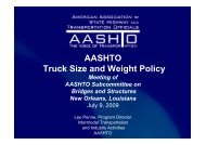
Fatigue Behavior of Welded Aluminum Light Poles - Menzemer
Fatigue Behavior of Welded Aluminum Light Poles - Menzemer
Fatigue Behavior of Welded Aluminum Light Poles - Menzemer

Create successful ePaper yourself
Turn your PDF publications into a flip-book with our unique Google optimized e-Paper software.
<strong>Fatigue</strong> <strong>Behavior</strong> <strong>of</strong> <strong>Welded</strong> <strong>Aluminum</strong> <strong>Light</strong><br />
<strong>Poles</strong><br />
Historical Perspective and Design Recommendations<br />
DR. CRAIG C . MENZEMER<br />
COLLEGE OF ENGINEERING<br />
THE UNIVERSITY OF AKRON<br />
JULY 2009
Objectives<br />
• Brief, historical perspective on aluminum fatigue design provisions<br />
• Existing fatigue data for welded aluminum light pole support details<br />
• Review research program sponsored by HAPCO at The University <strong>of</strong><br />
Akron<br />
• <strong>Fatigue</strong> test results from HAPCO research program<br />
• Parametric studies and fracture mechanics evaluation<br />
• Age old questions – how much, how long, are you sure…..<br />
• Design recommendations
Historical Perspective<br />
• 1986 First fatigue design specification published by the <strong>Aluminum</strong><br />
Association i in the U.S.<br />
• 1986 Specification based on primarily small scale fatigue specimens<br />
• Prior to the mid 1970’s, most fatigue data held by private and<br />
government laboratories<br />
• Effort started in the 1970’s to develop a fatigue data bank.<br />
Collaborative effort started with European colleagues.<br />
• Full – scale welded aluminum specimens evaluated during the 1980’s<br />
in Europe and the U.S.<br />
• Data sharing and extensive analysis resulted in current <strong>Aluminum</strong><br />
Association and ECCS fatigue design specifications<br />
• Current provisions utilize stress range and detail type as the primary<br />
variables that determine fatigue life for welded aluminum structures.
Historical Perspective – Questions / Answers<br />
• “Ray Minor Database” – since the late 1960’s relatively low failure rate<br />
for aluminum luminaire i poles<br />
• What failure rate is acceptable<br />
• Are the statistical limits adequate for an acceptable failure rate<br />
• Resistance versus load and design philosophy.
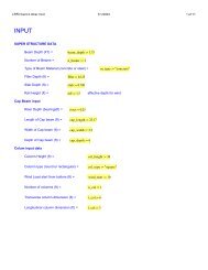
<strong>Fatigue</strong> Test Results<br />
ATLSS <strong>Fatigue</strong> Data Compared to ADM Provisions<br />
100<br />
Mean Curve, CategoryC, <strong>Aluminum</strong> Design Manual 2000<br />
nge (ksi)<br />
Stress Ra<br />
10<br />
Other Test Data<br />
Mean Curve, Category D, <strong>Aluminum</strong> Design Manual 2000<br />
Run-Out Data<br />
Lower Limit, Category D, <strong>Aluminum</strong> Design Manual 2000<br />
1<br />
1.0E+04 1.0E+05 1.0E+06 1.0E+07<br />
Cycles to Failure, N
HAPC and UA <strong>Fatigue</strong> Test Program<br />
• Comparative set <strong>of</strong> tests for cantilever type samples with two different<br />
base support details.<br />
• <strong>Poles</strong> inserted into bored shoebase castings and welded top to bottom<br />
Shoe base<br />
Through Plate
Project Components<br />
35<br />
Stress (ksi)<br />
30<br />
25<br />
20<br />
15<br />
24.5%<br />
27.6%<br />
27.6%<br />
26.25%<br />
10-0.188<br />
10-0.25<br />
10-0.3125<br />
10-0.375<br />
10<br />
5<br />
0<br />
0 1 2 3 4 5<br />
Plate Thickness (in)<br />
7<br />
6<br />
m m<br />
C rack length m<br />
5<br />
4<br />
3<br />
2<br />
38 MPa_t=25.4<br />
38 MPa_t=76.2<br />
38 MPa_shoe base<br />
1<br />
0<br />
0.E+00 2.E+05 4.E+05 6.E+05 8.E+05 1.E+06<br />
<strong>Fatigue</strong> life, N
Publications<br />
• Azzam, D. and <strong>Menzemer</strong>, C. C.<br />
• Residual Stress Measurement <strong>of</strong> <strong>Welded</strong> <strong>Aluminum</strong> <strong>Light</strong> Pole Supports, The Journal <strong>of</strong><br />
Structural Engineering, ASCE, Volume 132, No. 10, October 2006, pp. 1603 – 1610.<br />
• Azzam, D. and <strong>Menzemer</strong>, C. C.<br />
• <strong>Fatigue</strong> <strong>Behavior</strong> <strong>of</strong> <strong>Welded</strong> <strong>Aluminum</strong> <strong>Light</strong> Pole Support Details, The Journal <strong>of</strong> Structural<br />
Engineering, ASCE, Volume 132, No. 12, December 2006, pp. 1919 – 1927.<br />
• Azzam, D. and <strong>Menzemer</strong>, C. C.<br />
• Numerical Study <strong>of</strong> Stiffened Socket Connections for Highway Signs, Traffic Signals and<br />
Luminaire Structures, accepted, The Journal <strong>of</strong> Structural Engineering, ASCE, Vol. 134, No. 2,<br />
February 2008, pp. 173-180.<br />
• Azzam, D. and <strong>Menzemer</strong>, C. C.<br />
• <strong>Fatigue</strong> Life Assessment <strong>of</strong> <strong>Welded</strong> <strong>Aluminum</strong> <strong>Light</strong> Pole Structures, Bridge Structures:<br />
Assessment, Design and Construction, Taylor and Francis, Vol. 3, No. 1, March 2007, pp. 81-90.<br />
• Azzam, D., <strong>Menzemer</strong>, C. C. and Srivatsan, T.<br />
• Fracture Mechanics Evaluation <strong>of</strong> the <strong>Fatigue</strong> <strong>Behavior</strong> <strong>of</strong> <strong>Welded</strong> <strong>Aluminum</strong> <strong>Light</strong> <strong>Poles</strong>,<br />
Journal <strong>of</strong> Materials Engineering and Performance, to be submitted.
<strong>Fatigue</strong>- Test Results Shoe base<br />
Stress<br />
s rang e, ksi<br />
100<br />
Shoe base fatigue test t results<br />
Lower Limit, Category D, <strong>Aluminum</strong> Design Manual, 2005<br />
Lower Limit, Category E, <strong>Aluminum</strong> Design Manual, 2005<br />
Lower Limit, Category E', <strong>Aluminum</strong> Design Manual, 2005<br />
10<br />
CAFL, 3.3 ksi<br />
1<br />
0.1<br />
S =<br />
29.698<br />
0.1368<br />
N −<br />
CAFL, 2.5 ksi<br />
CAFL, 1.9 ksi<br />
CAFL, 1.0 ksi<br />
1.E+04 1.E+05 1.E+06 1.E+07 1.E+08<br />
Cycles to failure, N
<strong>Fatigue</strong> Test Results Through Plate<br />
Stress<br />
s rang ge, ks<br />
i100<br />
10<br />
1<br />
Through plate fatigue test results<br />
Lower Limit, Category D, <strong>Aluminum</strong> Design Manual, 2005<br />
Lower Limit, Category E, <strong>Aluminum</strong> Design Manual, 2005<br />
Lower Limit, Category E', <strong>Aluminum</strong> Design Manual, 2005<br />
S<br />
= 43 N<br />
− 0.1262<br />
CAFL,2.5 ksi<br />
CAFL,1.9 ksi<br />
CAFL,1.0 ksi<br />
CAFL,0.8 ksi<br />
0.1<br />
1.E+04 1.E+05 1.E+06 1.E+07 1.E+08<br />
Cycles to failure, N
Butterfly Trend<br />
Gage 2<br />
Gage 3<br />
ang e , k si<br />
tress R<br />
S<br />
2.8<br />
2.4<br />
2<br />
1.6<br />
1.2<br />
0.8<br />
0.4<br />
0<br />
-0.4<br />
-0.8<br />
-1.2 12<br />
-1.6<br />
-2<br />
-2.4 24<br />
4.5 ksi<br />
33 3.3 ksi<br />
Gage 1<br />
Gage 2<br />
Gage 3 - Opposite<br />
to bolt<br />
Gage 4<br />
Gage 5<br />
Gage 6<br />
2 2.2 2.4 2.6 2.8 3 3.2 3.4 3.6 3.8 4<br />
Elapsed time, sec
<strong>Fatigue</strong> Limits – <strong>Welded</strong> <strong>Aluminum</strong> Structures<br />
<strong>Aluminum</strong> Association, ECCS/ENV, BS<br />
10<br />
Runout <strong>Fatigue</strong> Data - ATLSS / UA<br />
ECCS/ENV (23 Mpa, 3.34 ksi)<br />
BS8118 (20 Mpa, 2.9 ksi)<br />
<strong>Aluminum</strong> Association (3.2 ksi)<br />
Shoe-base details<br />
1<br />
10E+06 1.0E+06 10E+07 1.0E+07 10E+08 1.0E+08
Suggested Specification Provision<br />
• Construction - Fillet<br />
<strong>Welded</strong> Connections<br />
• Application - Fillet welded<br />
tube to integrally stiffened cast<br />
base connection.<br />
• CAFL - Current D 2.5 ksi<br />
• CAFL - New Category 3.2 ksi<br />
• Detail - Base metal at a pair <strong>of</strong><br />
circumferential fillet welds at least<br />
0.48 D apart in the tubes<br />
longitudinal direction. Tubes shall<br />
be fit to a base with non-tapered<br />
bore. Fillet welds shall be sufficient<br />
to develop the static strength <strong>of</strong> the<br />
tube and be placed in the following<br />
order: weld the top <strong>of</strong> the base and<br />
tube followed by the end <strong>of</strong> the<br />
tube and bottom <strong>of</strong> base. The base<br />
shall be for a top mounted<br />
luminaire and short mast arms<br />
that result in a dead load stress <strong>of</strong> 5<br />
ksi or less.
Questions