Arrangement 4 - Cincinnati Fan
Arrangement 4 - Cincinnati Fan
Arrangement 4 - Cincinnati Fan

Create successful ePaper yourself
Turn your PDF publications into a flip-book with our unique Google optimized e-Paper software.
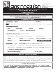
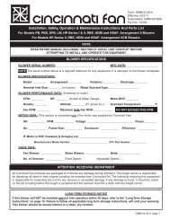
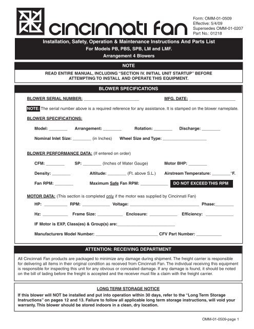
Installation, Safety, Operation & Maintenance Instructions And Parts List<br />
For Models PB, PBS, SPB, LM and LMF.<br />
<strong>Arrangement</strong> 4 Blowers<br />
NOTE<br />
READ ENTIRE MANUAL, INCLUDING “SECTION IV. INITIAL UNIT STARTUP” BEFORE<br />
ATTEMPTING TO INSTALL AND OPERATE THIS EQUIPMENT.<br />
BLOWER SPECIFICATIONS<br />
Form: OMM-01-0509<br />
Effective: 5/4/09<br />
Supersedes OMM-01-0207<br />
Part No.: 01218<br />
BLOWER SERIAL NUMBER: ________________________<br />
MFG. DATE: ____________________<br />
NOTE: The serial number above is a required reference for any assistance. It is stamped on the blower nameplate.<br />
BLOWER SPECIFICATIONS:<br />
Model: ________ <strong>Arrangement</strong>: ________ Rotation: ________ Discharge: ________<br />
Nominal Inlet Size: ________ (in Inches)<br />
Wheel Size and Type: ___________________<br />
BLOWER PERFORMANCE DATA: (If entered on order)<br />
CFM: ________ SP: ________ (Inches of Water Gauge) Motor BHP: ________<br />
Density: ________ Altitude: ________ (Ft. above S.L.) Airstream Temperature: ________°F.<br />
<strong>Fan</strong> RPM: ________ Maximum Safe <strong>Fan</strong> RPM: ____________ DO NOT EXCEED THIS RPM<br />
MOTOR DATA: (This section is completed only if the motor was supplied by <strong>Cincinnati</strong> <strong>Fan</strong>)<br />
HP: __________ RPM: ____________ Voltage: ______________________________ Phase:________<br />
Hz: ___________ Frame Size: ___________ Enclosure: ____________ Efficiency: ____________<br />
IF Motor is EXP, Class(es) & Group(s) are:_________________________<br />
Manufacturers Model Number: ___________________________ CFV Part Number: ___________<br />
ATTENTION: RECEIVING DEPARTMENT<br />
All <strong>Cincinnati</strong> <strong>Fan</strong> products are packaged to minimize any damage during shipment. The freight carrier is responsible<br />
for delivering all items in their original condition as received from <strong>Cincinnati</strong> <strong>Fan</strong>. The individual receiving this equipment<br />
is responsible for inspecting this unit for any obvious or concealed damage. If any damage is found, it should be noted<br />
on the bill of lading before the freight is accepted and the receiver must file a claim with the freight carrier.<br />
LONG TERM STORAGE NOTICE<br />
If this blower will NOT be installed and put into operation within 30 days, refer to the “Long Term Storage<br />
Instructions” on pages 12 and 13. Failure to follow all applicable long term storage instructions, will void your<br />
warranty. This blower should be stored indoors in a clean, dry location.<br />
OMM-01-0509-page 1
DANGER<br />
Hazardous voltage High speed rotating Lock out/Tag out to Avoid injury. NEVER Avoid injury. You MUST<br />
can cause electrical equipment can cause prevent personal injury operate without ALL read and understand all<br />
shock and death. severe personal injury. BEFORE starting ANY required safety instructions in this manual<br />
service or inspection. guards in place. BEFORE installing.<br />
TABLE OF CONTENTS<br />
I. GENERAL<br />
A. Unpacking and Handling .............................2<br />
B. Safety Accessories & Instructions............2-3<br />
II. INSTALLATION<br />
A. Vibration.......................................................3<br />
B. Mounting Methods....................................3-4<br />
C. Duct Work Connections...............................4<br />
D. Safety Guards..............................................4<br />
E. Dampers and Valves....................................4<br />
F. Set Screw & Taper-lock Bushing<br />
Torque Values ..............................................5<br />
III. ELECTRICAL<br />
A. Disconnect Switches ...................................5<br />
B. Motors.......................................................5-6<br />
C. Maximum Blower Speed..............................6<br />
IV. INITIAL UNIT STARTUP<br />
A. Pre-Startup & Post-Startup Checks.............7<br />
B. Vibration....................................................8-9<br />
V. ROUTINE INSPECTION & MAINTENANCE.....9<br />
A. Hardware ...................................................10<br />
B. Motor Bearing Lubrication .........................10<br />
C. Wheel Balance ..........................................10<br />
D. Vibration.....................................................10<br />
E. Dampers and Valves..................................10<br />
F. Safety Equipment or Accessories .........10-11<br />
VI. ORDERING PARTS .........................................11<br />
VII. TROUBLESHOOTING ................................11-12<br />
VIII. LONG TERM STORAGE ............................12-13<br />
IX. WARRANTY, LIABILITY & RETURNS............14<br />
X. PARTS DRAWING ...........................................15<br />
I. GENERAL<br />
A. Unpacking:<br />
Be careful not to damage or deform any parts of the blower when removing it from the packaging container. All the<br />
packaging material should be kept in the event the blower needs to be returned.<br />
Handling:<br />
Handling of the blower should be performed by trained personnel and be consistent with all safe handling practices.<br />
Verify that all lifting equipment is in good operating condition and has the proper lifting capacity. The blower should<br />
be lifted using well-padded chains, cables or lifting straps with spreader bars. Some blower models have lifting eye<br />
locations provided in the blower base. NEVER lift the blower by an inlet or discharge flange, motor shaft,<br />
motor eye bolt, or any other part of the blower assembly that could cause distortion of the blower<br />
assembly.<br />
B. Safety Instructions & Accessories:<br />
1. Safety Instructions:<br />
All installers, operators and maintenance personnel should read AMCA Publication 410-96, “Recommended Safety<br />
Practices for Users and Installers of Industrial and Commercial <strong>Fan</strong>s”. This manual is included with the blower.<br />
Additional copies can be requested by writing us at <strong>Cincinnati</strong> <strong>Fan</strong>, 7697 Snider Rd., Mason, OH 45040-9135<br />
2. Sound:<br />
Some blowers can generate sound that could be hazardous to personnel. It is the responsibility of the user to measure<br />
the sound levels of the blower and/or system, determine the degree of personnel exposure, and comply with all applicable<br />
safety laws and requirements to protect personnel from excessive noise.<br />
OMM-01-0509-page 2
3. Air Pressure and Suction:<br />
In addition to the normal dangers of rotating machinery, the blower can present additional hazards from the suction or<br />
pressure created at the blower inlet or discharge. Suction at the blower inlet can draw materials into the blower where<br />
they become high velocity projectiles at the discharge and cause severe personal injury or death. It can also be<br />
extremely dangerous to persons in close proximity to the inlet or discharge as the forces involved can overcome the<br />
strength of most individuals.<br />
WARNING<br />
NEVER OPERATE A BLOWER WITH A NON-DUCTED INLET AND/OR DISCHARGE. IF THE BLOWER INLET<br />
AND/OR DISCHARGE IS NON-DUCTED, IT IS THE USERS RESPONSIBILITY TO INSTALL AN<br />
INLET AND/OR DISCHARGE GUARD.<br />
4. Temperature:<br />
Many blowers, blower components and all motors operate at temperatures that could burn someone if they come in<br />
contact with them. If this potential hazard could exist in your installation, steps must be taken by the user to protect anyone<br />
from coming in contact with this equipment.<br />
5. Spark Resistance; (Per AMCA Standard 99-0401-86 and ISO 13499)<br />
DANGER<br />
NO GUARANTEE OF ANY LEVEL OF SPARK RESISTANCE IS IMPLIED BY SPARK RESISTANT<br />
CONSTRUCTION. IT HAS BEEN DEMONSTRATED THAT ALUMINUM IMPELLERS RUBBING ON RUSTY<br />
STEEL CAN CAUSE HIGH INTENSITY SPARKS. AIR STREAM MATERIAL AND DEBRIS OR OTHER SYSTEM<br />
FACTORS CAN ALSO CAUSE SPARKS.<br />
6. Safety Accessories;<br />
Guards:<br />
All moving parts must be guarded to protect personnel. Safety requirements can vary, so the number and types of<br />
guards required to meet company, local, state and OSHA regulations must be determined and specified by the actual<br />
user or operator of the equipment.<br />
NEVER start any blower without having all required safety guards properly installed. All blowers should be<br />
checked on a regular schedule, for missing or damaged guards. If any required guards are found to be missing<br />
or defective, the power to the blower should be immediately turned off and locked out in accordance with<br />
OSHA regulations. Power to the blower should NOT be tuned back on until the required guards have been<br />
repaired or replaced.<br />
This blower can become dangerous due to a potential “windmill” effect, even though all electrical power has been<br />
turned off or disconnected. The blower wheel should be carefully secured to prevent any rotational turning BEFORE<br />
working on any parts of the blower/motor assembly that could move.<br />
7. Access or Inspection Doors:<br />
DANGER<br />
NEVER OPEN ANY ACCESS OR INSPECTION DOORS WHILE THE BLOWER IS OPERATING. SERIOUS INJURY OR<br />
DEATH COULD RESULT FROM THE AFFECTS OF AIR PRESSURE, AIR SUCTION OR MATERIAL THAT IS BEING<br />
CONVEYED. DISCONNECT OR LOCK OUT POWER TO THE BLOWER AND LET THE BLOWER WHEEL COME TO A<br />
COMPLETE STOP BEFORE OPENING ANY TYPE OF ACCESS OR INSPECTION DOOR.<br />
II. INSTALLATION<br />
A. Vibration:<br />
Before any mounting method is selected, the user should be aware of the effects vibration will have on the blower,<br />
motor and other parts. Improper blower installation can cause excessive vibration causing premature wheel and/or<br />
motor bearing failure, that is not covered under warranty. Vibration eliminator pads, springs or bases should be properly<br />
installed to prevent any blower vibration from transmitting to the foundation, support structure or ducting.<br />
I<br />
WARNING<br />
SHUT THE BLOWER DOWN IMMEDIATELY IF THERE IS ANY SUDDEN INCREASE IN VIBRATION.<br />
B. Mounting Methods:<br />
1. Floor Mounted Units;<br />
Centrifugal blowers should be mounted on a flat, level, concrete foundation weighing 2-3 times the weight of the complete<br />
blower/motor assembly. It is recommended that the foundation be at least 6 inches larger than the base of the<br />
blower. The foundation should include anchor bolts such as shown in Fig. 1 on page 4. Place the blower over the<br />
anchor bolts and shim under each bolt until the blower is level. After shimming, flat washers, lock washers and lock nuts<br />
should be tightened at each anchor bolt. Any gaps between the blower base and the foundation should be grouted. If<br />
the blower will be sitting on some type of vibration pads or mounts, follow the recommended mounting procedures<br />
supplied with the vibration elimination equipment.<br />
OMM-01-0509-page 3
Fig. 1<br />
2. Elevated Units;<br />
Improper mounting of elevated blowers can cause vibration problems. The structure that the blower/motor assembly will<br />
be mounted on must be strong enough to support at least 3 times the weight of the entire blower/motor assembly. An<br />
insufficient support will cause excessive vibration and lead to premature wheel and/or motor bearing failure.<br />
Bracing of the support structure must be sufficient enough to prevent any side sway. The entire structure should be welded<br />
at all connection joints to maintain constant alignment of the platform.<br />
DANGER<br />
THE IMPROPER DESIGN OF AN ELEVATED PLATFORM STRUCTURE COULD RESULT IN A RESONANT<br />
CONDITION, AND CONSEQUENTLY, CAUSE A LIFE THREATENING, CATASTROPHIC, STRUCTURAL FAILURE.<br />
C. Duct Work Connections:<br />
All duct connections to the blower should include flexible connectors between the ducting and the blower inlet and/or discharge.<br />
This will eliminate distortion, noise and vibration from transmitting to the duct and building. The connectors<br />
should be selected to handle the operating conditions for air volume and pressure that the blower will produce. All ducting<br />
or accessories, added by the user, should be independently supported. DO NOT use the blower/motor<br />
assembly to support any additional weight. Inlet and/or discharge duct elbows should be located a minimum of 2<br />
blower wheel diameters from the blower. Any duct elbows located closer than 2 wheel diameters to the blower inlet or<br />
discharge WILL reduce the air performance and blower efficiency. Any duct elbows near the blower discharge should be<br />
in the same rotational direction as the blower rotation.<br />
Non-Ducted Blower Inlet:<br />
Any blower with no ducting on the inlet must have an inlet guard. The blower should be located so the blower inlet is, at<br />
least, 1 wheel diameter away from any wall or bulkhead to eliminate a reduction in air flow.<br />
Non-Ducted Blower Discharge:<br />
Any blower with no ducting on the discharge must have a discharge guard.<br />
D. Safety Guards:<br />
<strong>Cincinnati</strong> <strong>Fan</strong> offers guards, as optional, to keep your blower in compliance with OSHA safety regulations. These include<br />
inlet or discharge guards. Any blowers built with high temperature construction, a “heat slinger guard” is standard. It is<br />
the responsibility of the user to make sure this blower meets all local, state and OSHA safety regulations. If you have a<br />
specific guard requirement not covered by OSHA, please contact the local <strong>Cincinnati</strong> <strong>Fan</strong> sales office for assistance.<br />
E. Dampers and Valves: (Airflow control devices)<br />
If the blower is supplied with any type of air flow control device, it should be closed before initial start-up of the blower to<br />
minimize overloading of the motor. Any airflow control device, with bearings, should be maintained in accordance with<br />
the manufacturers instructions. Any air flow control device, with an automatic control mechanism, should be adjusted per<br />
the manufacturers recommendations.<br />
OMM-01-0509-page 4
F. Set Screw and Taper-lock Bushing Torque Values:<br />
All blower wheel set screws are tightened to the proper torque prior to shipment. Some wheels may have taper-lock<br />
hubs and split, taper-lock bushings to secure the wheel to the motor shaft.<br />
NOTE: Check all set screw or taper-lock bushing torques. Forces encountered during shipment, handling, rigging<br />
and temperature can affect factory settings. For correct torque values, see Tables 1 and 2 below.<br />
Diameter & Number<br />
of Treads/Inch<br />
1/4-20<br />
5/16-18<br />
3/8-16<br />
7/16-14<br />
1/2-13<br />
5/8-11<br />
Table 1<br />
SET SCREW TORQUE VALUES<br />
Hex Wrence Size<br />
(Across Flats)<br />
1/8”<br />
5/32”<br />
3/16”<br />
7/32”<br />
1/4”<br />
5/16”<br />
Required Torque<br />
(Inch Pounds)<br />
65<br />
165<br />
228<br />
348<br />
504<br />
1104<br />
Table 2<br />
TORQUE VALUES FOR<br />
TAPER-LOCK BUSHINGS<br />
Required Torque<br />
(Inch Pounds)<br />
Taper-lock<br />
Bushing Size<br />
H<br />
B<br />
P<br />
Q<br />
R<br />
95<br />
192<br />
192<br />
350<br />
350<br />
CAUTION<br />
Set screws should NEVER be used more than once. If the set screws are loosened, they MUST be replaced.<br />
Use only knurled, cup-point, set screws with a nylon locking patch.<br />
III. ELECTRICAL<br />
A. Disconnect Switches:<br />
All blower motors should have an independent disconnect switch located in close visual proximity to turn off the electrical<br />
service to the blower motor. Disconnects must be locked out in accordance with OSHA “lock out-tag out”<br />
procedures any time inspection or maintenance is being performed on the blower and/or motor assembly.<br />
The “lock out-tag out” procedure should be performed by a licensed electrician or authorized personnel.<br />
All disconnects should be sized in accordance with the latest NEC codes (National Electric Codes) and any local<br />
codes and should be installed only by a licensed electrician. “Slow blow” or “time delay” fuses or breakers should be<br />
used since the initial start-up time for the blower motor, although rare, can be up to 10 seconds.<br />
B. Motors:<br />
DANGER<br />
ALL WIRING CONNECTIONS, INSPECTION AND MAINTENANCE OF ANY MOTOR MUST BE PERFORMED BY A<br />
LICENSED ELECTRICIAN IN ACCORDANCE WITH THE MOTOR MANUFACTURERS RECOMMENDATIONS, ALL<br />
ELECTRICAL CODES AND OSHA REGULATIONS. FAILURE TO PROPERLY INSTALL, MAKE WIRING<br />
CONNECTIONS, INSPECT OR PERFORM ANY MAINTENANCE TO A MOTOR CAN RESULT IN<br />
MOTOR FAILURE, PROPERTY DAMAGE, EXPLOSION, ELECTRICAL SHOCK AND DEATH.<br />
1. DO NOT connect or operate a motor without reading the motor manufacturers instructions supplied with<br />
the blower. The basic principle of motor maintenance is: KEEP THE MOTOR CLEAN AND DRY. This requires<br />
periodic inspections of the motor. The frequency of the inspections depends on the type of motor, the service and<br />
environment it will be subjected to and the motor manufacturers instructions.<br />
2. Cleaning: Cleaning should be limited to exterior surfaces only. Follow motor manufacturers cleaning instructions.<br />
3. Lubrication: Most small motors have sealed bearings that are permanently lubricated for the life of the motor.<br />
Some larger motors have grease plugs that should be replaced with grease fittings to perform re-lubrication.<br />
These motors, or any motor with grease fittings, should be lubricated in accordance with the motor manufacturers<br />
recommendations. Lubrication frequency depends on the motor horsepower, speed and service. BE SURE you<br />
use compatible grease and DO NOT over grease.<br />
4. Location: If the motor will be outside and subjected to the weather, it is recommended that a weather cover be<br />
installed to keep rain and snow off of the motor. No motors are guaranteed to be “watertight”. Be careful to allow<br />
enough openings between the motor and the motor cover to let the motor ”breath”. If the back end of the motor is<br />
covered, the cover should be no closer than 3” to the back of the motor for proper ventilation.<br />
OMM-01-0509-page 5
5. Wiring Connections: All wiring connections should be made for the proper voltage and phase as shown on the<br />
motor nameplate. Connections should follow the motor manufacturers recommendations as shown on the wiring<br />
schematic. This wiring diagram will be located on the outside of the motor, inside of the motor conduit box or on the<br />
motor nameplate. Reversing some wires might be necessary to get the correct blower rotation.<br />
6. Motors with Thermal Overload Protection: If a motor is equipped with thermal overloads, the thermal overload<br />
must be wired per the wiring schematic to be operable. There are 3 types of thermal overloads:<br />
a. Automatic: These will automatically shut the motor down if the internal temperature exceeds the design limits.<br />
DANGER<br />
MAKE SURE YOU LOCK OUT THE POWER TO THE MOTOR BEFORE INSPECTING ANY MOTOR WITH<br />
AUTOMATIC THERMALS. WHEN THE THERMALS COOL DOWN, THEY WILL ALLOW THE MOTOR TO<br />
AUTOMATICALLY START UP AGAIN, UNLESS YOU HAVE LOCKED OUT THE POWER TO THE MOTOR.<br />
b. Manual: These motors will have a button on them. If the motor overheats, it will shut down. After you have<br />
inspected the motor and eliminated the over heating problem, you will need to “reset” it by pushing the button.<br />
You should still lock out the power BEFORE inspecting the motor.<br />
c. Thermostats: This type of thermal is a temperature sensing device ONLY. If the motor overheats, the thermostats<br />
will open or close (depending on the type) and send a “signal” to the electrical box. THEY WILL NOT<br />
TURN THE MOTOR OFF. These are pilot circuit devices that must be connected to the magnetic starter<br />
circuit.<br />
7. EXPLOSION PROOF Motors: No motor is explosion proof. Explosion proof (EXP) motors are designed so if there is<br />
an explosion WITHIN the motor, the explosion will be CONTAINED INSIDE the motor and not allowed to get out to<br />
the atmosphere. All explosion proof motors must be selected based on the atmosphere and/or the environment the<br />
motor will be operating in. Explosion proof motors are designed, rated, and labeled for their operating conditions<br />
based on Classes, Groups and “T” Codes. The Class, Group and “T” Code of an EXP motor MUST be selected<br />
based on the atmosphere and/or environmental conditions the motor will be operating in. Consult the NEC<br />
(National Electric Code) and the NFPA (National Fire Protection Association) for the proper EXP motor<br />
Class, Group and “T” Code required for your specific application and location.<br />
DANGER<br />
IF AN EXPLOSION PROOF MOTOR IS USED IN AN AREA CONTAINING VOLITILE LIQUIDS, GASES,<br />
FUMES OR DUST FOR WHICH THE MOTOR WAS NOT DESIGNED TO OPERATE IN, AN<br />
EXPLOSION AND/OR FIRE CAN OCCUR.<br />
NOTICE:<br />
a. All EXP motors have some type of thermal overload as required by UL (Underwriters Laboratories).<br />
Refer to all of Section 6 above.<br />
b. All EXP motors are required to have the UL (Underwriters Laboratories) and CSA (Canadian Standards<br />
Association) listing numbers on the motor name plate or on a separate plate attached to the motor. The<br />
Class, Group and “T” Code the motor is designed for must also be listed.<br />
8. Normal Motor Operating Temperatures:<br />
Using your hand to test the normal running temperature of a motor can be a very painful experience;<br />
The normal operating temperature of a fully loaded, open type, electric motor operating in a 70°F. (21° C.)<br />
ambient temperature is 174°F. (79° C.)<br />
C. Maximum Blower Speed and Motor Speed Controllers:<br />
If you will be using any type of motor speed controller with this blower, DO NOT exceed the maximum safe blower<br />
speed. Installing and using a speed control device requires special training and certification as required by the<br />
speed control manufacturer. See the manufacturers instructions for proper use, installation and wiring connections<br />
for the maximum speed settings. It may also be necessary to “block out” some speeds to eliminate a resonant vibration<br />
problem. The maximum safe blower speed is shown on the data sheet shipped with the blower. If you have lost<br />
the data sheet, contact <strong>Cincinnati</strong> <strong>Fan</strong> or our sales office for your area. You must have the serial number from the<br />
blower name plate for us to determine the maximum safe blower speed. <strong>Cincinnati</strong> <strong>Fan</strong> will only extend the motor<br />
manufacturers warranty, when used with a speed controlling device, if the motor has the words “Inverter Duty”<br />
marked on the motor name plate. If the motor does not have “Inverter Duty” marked on the motor name plate, and<br />
you have a motor failure, you will be required to contact the motor manufacturer for any service or warranty claims.<br />
OMM-01-0509-page 6
IV. INITIAL UNIT STARTUP<br />
NOTICE: Failure to complete and document all the following pre-startup and both post-startup<br />
checks, listed in sections A (below) and B on page 8, could void all warranties.<br />
A. Pre-Startup & Post-Startup Checks: (Check blocks as each step is completed. Retain this for your records.)<br />
A1. Pre-Startup Checks Completed By: ___________________________________ DATE: ___________________<br />
A2. 8 Hour, Post-Startup Checks Completed By: _______________________ DATE: ___________________<br />
A3. 3 Day, Post-Startup Checks Completed By: _____________________ DATE: ___________________<br />
MAKE SURE POWER TO THE MOTOR IS LOCKED OUT BEFORE STARTING PRE-STARTUP OR POST-STARTUP CHECKS.<br />
1. ■ ■ ■ If possible, CAREFULLY spin the blower wheel by hand to ensure it rotates freely and no rubbing or clicking noise is<br />
heard.<br />
2. ■ ■ ■ Check all blower, foundation and duct work hardware to make sure it is tight.<br />
3. ■ ■ ■ Check all blower wheel set screws to make sure they are tight per Table 1 on page 5.<br />
4. ■ ■ ■ If the wheel has a taper-lock bushing, make sure the bolts are tightened per Table 2 on page 5.<br />
5. ■ ■ ■ Make certain there is no foreign material in the blower or duct work that can become a projectile.<br />
6. ■ ■ ■ Make sure any inspection doors in the duct work are securely bolted or locked.<br />
7. ■ ■ ■ Ensure all electrical power components are properly sized and matched for your electrical system.<br />
8. ■ ■ ■ Check that all required guards are properly secured.<br />
9. ■ ■ ■ Any dampers should be fully opened and closed to make sure there is no binding or interference.<br />
10. ■ ■ ■ If your blower is mounted on an elevated support structure, make sure the structure is welded at all the joint connections<br />
and the structure is properly braced to prevent “side sway”.<br />
11. ■ ■ ■ Close any dampers to minimize load on motor. Especially on blowers with high temperature construction. Never subject<br />
a “cold” blower to a “hot” gas stream. If the blower will be handling “hot gases” greater than 150°F (65°C) it is<br />
imperative that the blower be subjected to a gradual rate of temperature increase, not to exceed 15°F/minute<br />
(8°C/minute). The same temperature limits are also important when the blower is experiencing a drop in temperature<br />
until the temperature drops down to 150°F (65°C). Only, when the entire blower has reached an equilibrium temperature<br />
of 150°F (65°C), or less, should the power be turned off.<br />
12. ■ ■ ■ Make sure the power source connections to the blower motor are per the motor manufacturers instructions.<br />
13. ■ ■ ■ Make sure the blower wheel is stationary prior to startup. Starting a blower with a wheel that is rotating backwards<br />
can cause wheel damage.<br />
14. ■ ■ ■ Apply power to the blower motor momentarily (i.e. “bump start”) to check for proper blower wheel rotation. If the blower<br />
is rotating in the wrong direction, reconnect the motor leads per the motor manufacturers wiring schematic. Blower<br />
rotation is determined by viewing the blower from the motor side of the blower, NOT from the inlet side. After<br />
reconnecting the leads, repeat this step. See Fig. 2 below.<br />
Fig. 2<br />
Clockwise<br />
(CW) Rotation<br />
Counter-Clockwise<br />
(CCW) Rotation<br />
15. ■ ■ ■ Apply power to the blower motor and let it come up to full speed. Turn off the power. Look and listen for any unusual<br />
noise or mechanical abnormality while the blower wheel is still spinning. If any are noticed, lock out the power, wait for<br />
the blower wheel to come to a complete stop, locate the cause and correct it.<br />
16. ■ ■ ■ Unlock power and start the blower.<br />
17. ■ ■ ■ Measure, record and keep the following motor data for future reference and comparison:<br />
(Single phase motors will only have L1 and L2 leads)<br />
Amperage draw on each motor lead: L1 _______ L2 _______ L3 _______<br />
(Running amps SHOULD NOT exceed the motor nameplate amps for the voltage being operated on)<br />
Voltage coming to motor leads: L1_______ L2_______ L3_______<br />
(Should be about the same input voltage on all leads)<br />
OMM-01-0509-page 7
B. Vibration:<br />
The blower was balanced at the factory to comply with ANSI/AMCA Standard 204-05, Category BV-2. However, rough<br />
handling in shipment and/or erection, weak and/or non-rigid foundations, and misalignment may cause a vibration problem<br />
after installation. After installation, the vibration levels should be checked by personnel experienced with vibration<br />
analysis and vibration analysis equipment.<br />
NOTE:<br />
The blower SHOULD NOT be operated if the vibration velocity of the fan exceeds 0.50 inches per second, filter<br />
out, if the blower is rigidly mounted. If the blower is mounted on isolators or on an isolator base, it SHOULD<br />
NOT be operated if the vibration velocity of the blower exceeds 0.75 inches per second, filter out.<br />
Vibration readings for direct driven blowers should be taken on the motor at the top, sides and end as per Fig. 3 below.<br />
After you have taken your vibration readings, write them down in the spaces below and keep for future comparison.<br />
DANGER<br />
If the blower is going to be conveying material, it is the users responsibility to periodically turn the blower off and<br />
lock out the power. The blower wheel should then be checked for material build-up and/or erosion. If material has<br />
built up on any parts of the wheel, it MUST be removed and cleaned before it is put back into service. If any parts<br />
of the wheel have been eroded, the wheel MUST be replaced. Failure to perform this inspection can cause<br />
excessive vibration that will damage the blower and/or motor bearings. When vibration becomes excessive, it will<br />
lead to complete blower failure that could cause property damage, severe personal injury and death. The user<br />
must determine the frequency of this inspection based on the actual circumstances of their operation, BUT<br />
checking the vibration readings should NEVER exceed a 12 month period. For the AMCA/ANSI standard for<br />
vibration limits, see Fig. 4 on page 9.<br />
Fig. 3<br />
VIBRATION METER PROBE POSITIONS<br />
For <strong>Arrangement</strong> 4 Blowers<br />
OMM-01-0509-page 8
Fig. 4 Vibration Severity Chart<br />
V. ROUTINE INSPECTION & MAINTENANCE<br />
Periodic inspection of all the blower parts is the key to good maintenance and trouble-free operation. The frequency of<br />
inspections must be determined by the user and is dependent upon the severity of the application. BUT, it should<br />
NEVER exceed a 12 month period. The user should prepare an inspection and maintenance schedule and make sure<br />
it is adhered to.<br />
WARNING<br />
BEFORE STARTING ANY INSPECTION OR MAINTENANCE, BE SURE BLOWER IS TURNED OFF, POWER IS LOCKED<br />
OUT AND THE BLOWER WHEEL HAS BEEN CAREFULLY SECURED TO PREVENT WIND MILLING. IF THE<br />
OPERATING CONDITIONS OF THE BLOWER ARE TO BE CHANGED (SPEED, PRESSURE, TEMPERATURE, ETC.)<br />
CONSULT CINCINNATI FAN, OR OUR SALES OFFICE FOR YOUR TERRITORY, TO DETERMINE IF THE UNIT WILL<br />
OPERATE SAFELY AT THE NEW CONDITIONS.<br />
OMM-01-0509-page 9
A. Hardware:<br />
All blower and foundation hardware should be checked to make sure it is tight. Wheel set screws or taper-lock bushings<br />
should be tightened to the torque values shown in Tables 1 and 2 on page 5.<br />
NOTE: If any set screws have come loose, they must be thrown away and replaced. NEVER use set screws more<br />
than once. Replace with knurled, cup-point set screws with a nylon locking patch.<br />
B. Motor Bearing Lubrication:<br />
1. Motor Bearings:<br />
Most smaller motors have sealed bearings that never require re-lubrication for the life of the motor. For any motors with<br />
grease fittings, consult the motor manufacturers recommendations with reference to the lubrication frequency and the<br />
type of grease that should be used.<br />
DO NOT over grease the motor bearings. Generally, 1-2 shots should be enough. Use a hand operated grease gun at<br />
no more than 40 PSI. IF POSSIBLE, CAREFULLY lubricate the motor bearings while the motor is running.<br />
C. Wheel Balance:<br />
All blower wheels are balanced at the factory. It is not uncommon that additional “trim balancing” is required after the<br />
blower is assembled. Trim balancing of the blower assembly, in the field, is typically always necessary for all replacement<br />
wheels. After any wheel is installed, the final balance of the entire blower assembly should be checked.<br />
Refer to Section B on page 8 and Fig. 4 on page 9. Air stream material or chemicals can cause abrasion or corrosion<br />
of the blower parts. This wear is generally uneven and, over time, will lead to the wheel becoming unbalanced, causing<br />
excessive vibration. When that happens, the wheel must be rebalanced or replaced. The other air stream components<br />
should also be inspected for wear or structural damage and cleaned or replaced if necessary. After cleaning any<br />
blower wheel, it should be balanced and then “trim balanced” on the motor shaft.<br />
There are three ways to balance a blower wheel:<br />
1. Add balancing weights for fabricated aluminum, steel or stainless steel wheels:<br />
Balance weights should be rigidly attached to the wheel at a location that will not interfere with the blower<br />
housing nor disrupt air flow. They should (if at all possible) be welded to the wheel. When trim balancing the<br />
wheel, on the blower, be sure to ground the welder directly to the blower wheel. Otherwise, the welding<br />
current will likely pass through the motor and damage the motor bearings.<br />
2. Grinding off material for cast aluminum wheels:<br />
If you are grinding on the wheel to remove material, be very careful not to grind too much in one area. That<br />
could affect the structural integrity of the wheel.<br />
3. Forward curved wheels, Model LM only (also known as squirrel cage or multivane wheels).<br />
These wheels have balancing clips attached to individual blades around the wheel. That is the only proper<br />
way to balance this type of wheel.<br />
NOTE:<br />
Removing any forward curve wheel from the blower to clean it, requires special attention when reinstalling<br />
the wheel back into the blower housing. Make sure you reinstall the wheel so the proper wheel-to-inlet<br />
clearance is maintained. Failure to do this will affect the blowers airflow (CFM), static pressure (SP) capabilities<br />
and efficiency. Consult <strong>Cincinnati</strong> <strong>Fan</strong> or our local sales office for your area for assistance if necessary.<br />
D. Vibration:<br />
As mentioned previously in this manual, excessive vibration can cause premature motor bearing failure that could lead<br />
to catastrophic failure of the blower. After performing any routine maintenance, the vibration readings should be taken<br />
again. New readings should be taken (maximum every 12 months) and compared to the readings you recorded in<br />
Figure 3, on page 8, during the initial startup. If any major differences are present, the cause should be determined<br />
and corrected before the blower is put back into operation.<br />
The most common causes of vibration problems are:<br />
1. Wheel unbalance. 3. Poor blower inlet and/or discharge conditions.<br />
2. Mechanical looseness. 4. Foundation stiffness.<br />
E. Dampers and Valves: (Airflow control devices)<br />
Turn off and lock out power to the blower motor. Any dampers or valves should be periodically inspected to make sure<br />
all parts are still operable within their full range and there is no interference with any other damper or blower components.<br />
Any bearings or seals should be checked for their proper function. The manufacturers maintenance instructions<br />
should be followed.<br />
F. Safety Equipment & Accessories:<br />
It is the users responsibility to make sure that all safety guards required by the company, local, state and OSHA regulations<br />
are properly attached and fully functional at all times. If any guards become defective or non-functional at any<br />
time, the power to the blower MUST be turned off and locked out until complete repairs and/or replacements have<br />
been made, installed and inspected by authorized personnel.<br />
OMM-01-0509-page 10
Any accessories used in conjunction with the blower should also be inspected to make sure they are functioning<br />
within their intended limits and design specifications. The manufacturers maintenance manuals should be referred to<br />
for correct maintenance procedures. These accessories include, but are not limited to, the following:<br />
Shaft seals, inspection doors, vibration isolators or vibration bases, air flow or pressure measuring equipment,<br />
hoods, controls, special coatings, silencers, expansion joints, valves, flexible connectors and filters.<br />
VI. ORDERING REPLACEMENT PARTS:<br />
Under normal conditions, you should not need any spare or replacement parts for at least 24 months after shipment<br />
from <strong>Cincinnati</strong> <strong>Fan</strong>. That does not include any wear due to abrasion, corrosion, excessive temperatures, abuse, misuse,<br />
accident or any severe conditions the fan was not designed for.<br />
NOTICE:<br />
1. If this blower is vital to any process that could cost you lost revenue, we strongly recommend that you keep<br />
a replacement blower wheel and motor at your location.<br />
2. If this blower is vital for the safety of any people and/or animals, we strongly recommend that you keep a<br />
complete blower/motor assembly, as originally ordered, at your location.<br />
To order any parts or complete units, contact us for the name of our sales office for your area. Or you can find<br />
them on our website at: www.cincinnatifan.com<br />
WE MUST HAVE THE BLOWER SERIAL NUMBER FROM THE BLOWER NAME PLATE TO IDENTIFY PARTS CORRECTLY.<br />
VII. TROUBLESHOOTING<br />
DANGER<br />
Troubleshooting should only be performed by trained personnel. Any potential electrical problems should only<br />
be checked by a licensed electrician. All safety rules, regulations and procedures MUST be followed. Failure to<br />
follow proper procedures can cause property damage, severe bodily injury and death.<br />
Potential problems and causes listed below are in no order of importance or priority. The causes are only a list<br />
of the most common items to check to correct a problem. If you find the cause of a problem, DO NOT assume it is<br />
the ONLY cause of that problem. Different problems can have the same causes.<br />
PROBLEM<br />
Excessive Vibration<br />
Airflow (CFM) Too Low<br />
Airflow (CFM) Too High<br />
CAUSE<br />
1. Loose mounting bolts, wheel set screws, taper-lock hubs.<br />
2. Worn or corroded blower wheel.<br />
3. Accumulation of foreign material on blower wheel.<br />
4. Bent motor shaft.<br />
5. Worn motor bearings.<br />
6. Motor out of balance.<br />
7. Inadequate structural support.<br />
8. Support structure not sufficiently cross braced.<br />
9. Weak or resonant foundation.<br />
10. Foundation not flat and level.<br />
1. Blower wheel turning in wrong direction (rotation).<br />
2. Actual system static pressure (SP) is higher than expected.<br />
3. Motor speed (RPM) too low.<br />
4. Dampers or valves not adjusted properly.<br />
5. Leaks or obstructions in duct work.<br />
6. Filters dirty.<br />
7. Inlet and/or discharge guards are clogged.<br />
8. Duct elbow too close to blower inlet and/or discharge.<br />
9. Improperly designed duct work<br />
10. Blower wheel not properly located relative to the inlet bell (LM Model only).<br />
1. Actual system static pressure (SP) is lower than expected.<br />
2. Motor speed (RPM) too high.<br />
3. Filter not in place.<br />
4. Dampers or valves not adjusted properly.<br />
OMM-01-0509-page 11
VIII. LONG TERM STORAGE INSTRUCTIONS: (Storage exceeding 30 days after receipt of equipment)<br />
NOTE: Failure to adhere to these instructions voids all warranties in their entirety.<br />
1. Storage site selection:<br />
a. Level, well-drained, firm surface, in clean, dry and warm location. Minimum temperature of 50°F (10°C).<br />
b. Isolated from possibility of physical damage from construction vehicles, erection equipment, etc.<br />
c. Accessible for periodical inspection and maintenance.<br />
2. The blower should be supported under each corner of its base to allow it to “breath”. Supports (2 x 4’s, timbers, or<br />
railroad ties) should be placed diagonally under each corner.<br />
3. If the equipment is to be stored for more than three (3) months, the entire blower assembly must be loosely covered<br />
with plastic, but not tightly wrapped.<br />
4. Storage Maintenance:<br />
A periodic inspection and maintenance log, by date and action taken, must be developed and maintained<br />
for each blower. See example below. Each item must be checked monthly.<br />
EXAMPLE:<br />
Storage / Maintenance Schedule Log<br />
Long Term Storage instructions continued on page 13.<br />
OMM-01-0509-page 12
5. General Motor Procedure:<br />
If the motor is not put into service immediately, the motor must be stored in a clean, dry, warm location. Minimum<br />
temperature of 50°F. (10°C,). Several precautionary steps must be performed to avoid motor damage during storage.<br />
a. Use a “Megger” each month to ensure that integrity of the winding insulation has been maintained. Record the<br />
Megger readings. Immediately investigate any significant drop in insulation resistance.<br />
b. DO NOT lubricate the motor bearings during storage. Motor bearings are packed with grease at the factory.<br />
c. If the storage location is damp or humid, the motor windings must be protected from moisture. This can be done<br />
by applying power to the motor’s space heaters, (IF AVAILABLE) while the motor is in storage. If the motor does<br />
not have space heaters, storing it in a damp or humid location will, very quickly, cause internal corrosion and<br />
motor failure which is not warranted.<br />
NOTE:<br />
For specific storage instructions, for the actual motor and any accessory parts that were supplied, refer to<br />
the manufacturer’s instructions.<br />
OMM-01-0509-page 13
IX. LIMITED WARRANTY:<br />
<strong>Cincinnati</strong> <strong>Fan</strong> & Ventilator Company (Seller) warrants products of its own manufacture, against defects of material and workmanship<br />
under normal use and service for a period of eighteen (18) months from date of shipment or twelve (12) months from date of installation,<br />
whichever occurs first. This warranty does not apply to any of Seller’s products or any part thereof which has been subject to<br />
extraordinary wear and tear, improper installation, accident, abuse, misuse, overloading, negligence or alteration. This warranty does<br />
not cover systems or materials not of Seller’s manufacture. On products furnished by Seller, but manufactured by others, such as<br />
motors, Seller extends the same warranty as Seller received from the manufacturer thereof. Expenses incurred by Purchaser’s in<br />
repairing or replacing any defective product will not be allowed except where authorized in writing and signed by an officer of the<br />
Seller.<br />
The obligation of the Seller under this warranty shall be limited to repairing or replacing F.O.B. the Seller’s plant, or allowing credit at<br />
Seller’s option. THIS WARRANTY IS EXPRESSLY IN LIEU OF ALL OTHER WARRANTIES EITHER EXPRESSED OR IMPLIED<br />
INCLUDING THE WARRANTIES OF MERCHANTABILITY AND FITNESS FOR A PARTICULAR PURPOSE AND OF ALL OTHER<br />
OBLIGATIONS AND LIABILITIES OF THE SELLER. THE PURCHASER ACKNOWLEDGES THAT NO OTHER REPRESENTA-<br />
TIONS WERE MADE TO PURCHASER OR RELIED UPON BY PURCHASER WITH RESPECT TO THE QUALITY OR FUNCTION<br />
OF THE PRODUCTS HEREIN SOLD.<br />
Removal of the Sellers nameplate or any generic fan nameplate containing the fan serial number voids all warranties, either written or<br />
implied. Failure to complete and document all the pre-startup and post startup checks and perform the suggested routine maintenance<br />
checks voids all warranties, either written or implied.<br />
LIMITATION OF LIABILITY:<br />
Notice of any claim, including a claim for defect in material or workmanship, must be given to Seller in writing within 30 days after<br />
receipt of the equipment or other products. Seller reserves the right to inspect any alleged defect at Purchaser’s facility before any<br />
claim can be allowed and before adjustment, credit, allowance replacement or return will be authorized. See RETURNS below.<br />
Seller’s liability with respect to such defects will be limited to the replacement, free of charge, of parts returned at Purchaser’s<br />
expense F.O.B. Seller’s plant and found to be defective by the Seller.<br />
IN NO EVENT WILL SELLER BE LIABLE FOR SPECIAL, INDIRECT, INCIDENTAL OR CONSEQUENTIAL DAMAGES, WHETHER<br />
IN CONTACT, TORT, NEGLIGENCE, STRICT LIABILITY OR OTHERWISE, INCLUDING WITHOUT LIMITATION DAMAGES FOR<br />
INJURY TO PERSONS OR PROPERTY, LOST PROFITS OR REVENUE, LOST SALES OR LOSS OF USE OF ANY PRODUCT<br />
SOLD HEREUNDER. PURCHASER’S SOLE AND EXCLUSIVE REMEDY AGAINST SELLER WILL BE THE REPLACEMENT OF<br />
DEFECTIVE PARTS AS PROVIDED HEREIN OR REFUND OF THE PURCHASE PRICE FOR DEFECTIVE PRODUCTS, AT SELL-<br />
ER’S SOLE OPTION. SELLER’S LIABILITY ON ANY CLAIM, WHETHER IN CONTRACT, TORT, NEGLIGENCE, STRICT LIABILI-<br />
TY OR OTHERWISE, FOR ANY LOSS OR DAMAGE ARISING OUT OF OR IN CONNECTION WITH PURCHASER’S ORDER OR<br />
THE PRODUCTS OR EQUIPMENT PURCHASED HEREUNDER, SHALL IN NO CASE EXCEED THE PURCHASE PRICE OF THE<br />
EQUIPMENT GIVING RISE TO THE CLAIM.<br />
RESPONSIBILITY:<br />
It is the understanding of the Seller that Purchaser and/or User will use this equipment in conjunction with additional equipment or<br />
accessories to comply with all Federal, State and local regulations. The Seller assumes no responsibility for the Purchaser’s or Users<br />
compliance with any Federal, State and local regulations.<br />
RETURNS:<br />
<strong>Cincinnati</strong> <strong>Fan</strong> & Ventilator Company assumes no responsibility for any material returned to our plant without our permission. An RMA<br />
(Return Material Authorization) number must be obtained and clearly shown on the outside of the carton or crate and on a packing<br />
slip. Any items returned must be shipped freight prepaid. Failure to comply will result in refusal of the shipment at our receiving<br />
department.<br />
DISCLAIMER<br />
This manual, and all its content herein, is based on all applicable known material at the time this manual was created. Any parts of<br />
this manual are subject to change at any time and without notice.<br />
If any statements, diagrams and/or instructions contained herein, for components not manufactured by the Seller, conflict with<br />
instructions in the manufacturer’s manual (i.e.: motors, dampers, etc.), the instructions in the manufacturer’s manual, for that component<br />
take precedent.<br />
Should you want the latest version of this manual, please contact us or our sales office for your area. Or, you can print a current version<br />
by going to our website at: www.cincinnatifan.com<br />
7697 Snider Road, Mason, OH 45040-9135<br />
Phone: (513) 573-0600 Fax: (513) 573-0640<br />
E-Mail: sales@cincinnatifan.com<br />
OMM-01-0509-page 14
X. PARTS DRAWING:<br />
PLEASE NOTE<br />
<strong>Cincinnati</strong> <strong>Fan</strong> manufactures many models and arrangements with special variations. For that<br />
reason, the maintenance manuals contained on our website do not include a parts drawing nor the<br />
completed blower or fan specifications on page 1. For the parts drawing of all the standard<br />
components and specifications for the specific blower or fan that you have, please contact our local<br />
<strong>Cincinnati</strong> <strong>Fan</strong> sales office for your area.<br />
You will need to give them the serial number shown on the blower or fan nameplate so they can<br />
supply you the correct information.<br />
Click on “Contact a Sales Rep” on our website for the name and contact information for our local<br />
sales office for your area.<br />
www.cincinnatifan.com<br />
OMM-01-0509-page 15