
Create successful ePaper yourself
Turn your PDF publications into a flip-book with our unique Google optimized e-Paper software.
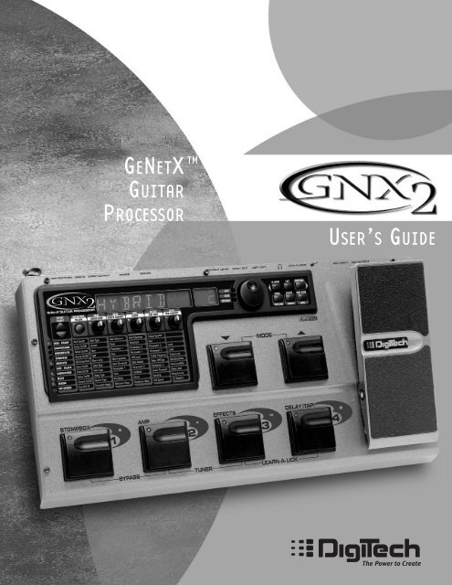
TM<br />
GENETX<br />
GUITAR<br />
PROCESSOR<br />
USER’S GUIDE
I<br />
These symbols are internationally accepted symbols that warn of potential<br />
hazards with electrical products.The lightning flash means that there are<br />
dangerous voltages present within the unit.The exclamation point indicates<br />
that it is necessary for the user to refer to the owners manual.<br />
These symbols warn that there are no user serviceable parts inside the unit.<br />
Do not open the unit. Do not attempt to service the unit yourself. Refer all<br />
servicing to qualified personnel. Opening the chassis for any reason will void<br />
the manufacturer’s warranty. Do not get the unit wet. If liquid is spilled on<br />
the unit, shut it off immediately and take it to a dealer for service.<br />
Disconnect the unit during storms to prevent damage.<br />
U.K. Mains Plug Warning<br />
A molded mains plug that has been cut off from the cord is unsafe.<br />
Discard the mains plug at a suitable facility. Never under any circumstances<br />
should you insert a damaged or cut mains plug into a 13<br />
amp power socket. Do not use the mains plug without the fuse cover<br />
in place. Replacement fuse covers can be obtained from your local retailer.<br />
Replacement fuses are 13 amps and MUST be ASTA approved to<br />
BS1362.<br />
Safety Instructions<br />
Notice for customers if your unit is equipped with a power cord.<br />
Warning:This appliance must be earthed.<br />
The cores in the mains lead are colored in accordance with the following<br />
code:<br />
Green and Yellow - Earth Blue - Neutral Brown - Live<br />
As colors of the cores in the mains lead of this appliance may not correspond<br />
with the colored markings identifying the terminals in your plug, proceed<br />
as follows:<br />
•The core which is colored green and yellow must be connected to the<br />
terminal in the plug marked with the letter E, or with the earth symbol,<br />
or colored green, or green and yellow.<br />
•The core which is colored blue must be connected to the terminal<br />
marked N, or colored black.<br />
•The core which is colored brown must be connected to the terminal<br />
marked L, or colored red.<br />
This equipment may require the use of a different line cord, attachment<br />
plug, or both, depending on the available power source at installation. If the<br />
attachment plug needs to be changed, refer servicing to qualified service<br />
personnel who should refer to the table below.The green/yellow wire shall<br />
be connected directly to the unit’s chassis.<br />
CONDUCTOR<br />
L<br />
N<br />
E<br />
LIVE<br />
NEUTRAL<br />
EARTH GND<br />
Normal Alt<br />
BROWN<br />
BLUE<br />
GREEN/YEL<br />
WIRE COLOR<br />
BLACK<br />
WHITE<br />
GREEN<br />
Warning: If the ground plug is defeated, certain fault conditions in the unit<br />
or in the system to which it is connected can result in full line voltage<br />
between chassis and earth ground. Severe injury or death can then result if<br />
the chassis and earth ground are touched simultaneously.<br />
Warning<br />
For your protection, please read the following:<br />
Water and Moisture: Appliances should not be used near water<br />
(e.g. near a bathtub, washbowl, kitchen sink, laundry tub, in a wet<br />
basement, or near a swimming pool, etc.) Care should be taken so<br />
that objects do not fall and liquids are not spilled into the enclosure<br />
through openings.<br />
Power Sources: The appliance should be connected to a power<br />
supply only of the type described in the operating instructions or as<br />
marked on the appliance.<br />
Grounding or Polarization: Precautions should be taken so that<br />
the grounding or polarization means of an appliance is not defeated.<br />
Power Cord Protection: Power supply cords should be routed so<br />
that they are not likely to be walked on or pinched by items placed<br />
upon or against them, paying particular attention to cords at plugs,<br />
convenience receptacles, and the point where they exit from the<br />
appliance.<br />
Servicing: To reduce the risk of fire or electrical shock, the user<br />
should not attempt to service the appliance beyond that described in<br />
the operating instructions.All other servicing should be referred to<br />
qualified service personnel.<br />
For units equipped with externally accessible fuse receptacle:<br />
Replace fuse with same type and rating only.<br />
Electromagnetic Compatibility<br />
Operation is subject to the following conditions:<br />
•This device may not cause harmful interference.<br />
•This device must accept any interference received, including<br />
interference that may cause undesired operation.<br />
•Use only shielded interconnecting cables.<br />
•Operation of this unit within significant electromagnetic fields<br />
should be avoided.
DECLARATION OF CONFORMITY<br />
Manufacturer’s Name: DigiTech<br />
Manufacturer’s Address: 8760 S. Sandy Parkway<br />
Sandy, Utah 84070, USA<br />
declares that the product:<br />
Product name: <strong>GNX2</strong><br />
Note: Product name may be suffixed by the letters EX, EU, JA, and UK.<br />
Product option: all (requires Class II power adapter that conforms to the requirements of EN60065, EN60742, or equivalent.)<br />
conforms to the following Product Specifications:<br />
Safety: IEC60065 (1998)<br />
EN 60065 (1993)<br />
EMC: EN 55013 (1990)<br />
EN 55020 (1991)<br />
Supplementary Information:<br />
The product herewith complies with the requirements of the Low Voltage Directive 72/23/EEC and the EMC Directive 89/336/EEC as amended<br />
by Directive 93/68/EEC.<br />
DigiTech / Johnson<br />
8760 S. Sandy Parkway<br />
Sandy, Utah 84070, USA<br />
Date: May 25, 2001<br />
European Contact:Your local DigiTech / Johnson Sales and Service Office or<br />
Harman Music Group<br />
8760 South Sandy Parkway<br />
Sandy, Utah<br />
84070 USA<br />
Ph: (801) 566-8800<br />
Fax: (801) 568-7573<br />
Warranty<br />
We at DigiTech are very proud of our products and back-up each one we sell with the following warranty:<br />
1.The warranty registration card must be mailed within ten days after purchase date to validate this warranty.<br />
2. DigiTech warrants this product, when used solely within the U.S., to be free from defects in materials and workmanship<br />
under normal use and service.<br />
3. DigiTech liability under this warranty is limited to repairing or replacing defective materials that show evidence of defect, provided<br />
the product is returned to DigiTech WITH RETURN AUTHORIZATION, where all parts and labor will be covered up to<br />
a period of one year. A Return Authorization number may be obtained from DigiTech by telephone.The company shall not be<br />
liable for any consequential damage as a result of the product's use in any circuit or assembly.<br />
4. Proof-of-purchase is considered to be the burden of the consumer.<br />
5. DigiTech reserves the right to make changes in design, or make additions to, or improvements upon this product without<br />
incurring any obligation to install the same on products previously manufactured.<br />
6.The consumer forfeits the benefits of this warranty if the product's main assembly is opened and tampered with by anyone<br />
other than a certified DigiTech technician or, if the product is used with AC voltages outside of the range suggested by the<br />
manufacturer.<br />
7.The foregoing is in lieu of all other warranties, expressed or implied, and DigiTech neither assumes nor authorizes any person<br />
to assume any obligation or liability in connection with the sale of this product. In no event shall DigiTech or its dealers<br />
be liable for special or consequential damages or from any delay in the performance of this warranty due to causes beyond<br />
their control.<br />
NOTE:The information contained in this manual is subject to change at any time without notification. Some information contained<br />
in this manual may also be inaccurate due to undocumented changes in the product or operating system since this version of the<br />
manual was completed.The information contained in this version of the owner's manual supersedes all previous versions.<br />
II
Introduction . . . . . . . . . . . . . . . . . . . . . . . . . . .1<br />
Quick Start . . . . . . . . . . . . . . . . . . . . . . . . . . . . . . . .2<br />
Making Connections . . . . . . . . . . . . . . . . . . . . . .2<br />
Apply Power . . . . . . . . . . . . . . . . . . . . . . . . . . . .2<br />
Select an Output Mode . . . . . . . . . . . . . . . . . . .2<br />
Select The Target System Setup . . . . . . . . . . . . . .2<br />
Select a Preset . . . . . . . . . . . . . . . . . . . . . . . . . .2<br />
A Guided Tour of the <strong>GNX2</strong> . . . . . . . . . . . . . . . . . .3<br />
The Front Panel . . . . . . . . . . . . . . . . . . . . . . . . .3<br />
The Rear Panel . . . . . . . . . . . . . . . . . . . . . . . . . .6<br />
Getting Started . . . . . . . . . . . . . . . . . . . . . . . . . . . . .7<br />
Making Connections . . . . . . . . . . . . . . . . . . . . . .7<br />
Mono Operation . . . . . . . . . . . . . . . . . . . . .7<br />
Stereo Operation . . . . . . . . . . . . . . . . . . . . .7<br />
Direct to a Mixing Console . . . . . . . . . . . . .8<br />
S/PDIF Digital Output . . . . . . . . . . . . . . . . . . . . .8<br />
Applying Power . . . . . . . . . . . . . . . . . . . . . . . . .8<br />
About the <strong>GNX2</strong> . . . . . . . . . . . . . . . . . . . . . . . . . . .9<br />
The Presets . . . . . . . . . . . . . . . . . . . . . . . . . . . .9<br />
Performance Mode . . . . . . . . . . . . . . . . . . . . . . .9<br />
Preset Mode . . . . . . . . . . . . . . . . . . . . . . . . . . . .9<br />
FX Mode . . . . . . . . . . . . . . . . . . . . . . . . . . . . . .9<br />
The Footswitches . . . . . . . . . . . . . . . . . . . . . . . .10<br />
The Expression Pedal . . . . . . . . . . . . . . . . . . . .10<br />
Bypass Mode . . . . . . . . . . . . . . . . . . . . . . . . . . .10<br />
Tuner Mode . . . . . . . . . . . . . . . . . . . . . . . . . . . .10<br />
Jam-A-Long . . . . . . . . . . . . . . . . . . . . . . . . . . . . .10<br />
Learn-A-Lick Mode . . . . . . . . . . . . . . . . . . . . . . .11<br />
Rhythm Trainer . . . . . . . . . . . . . . . . . . . . . . . . . .11<br />
Editing Functions . . . . . . . . . . . . . . . . . . . . .13<br />
Editing/Creating a Preset . . . . . . . . . . . . . . . . . . . . . .13<br />
Amp/Cabinet Modeling . . . . . . . . . . . . . . . . . . . . . . .13<br />
Amp Models . . . . . . . . . . . . . . . . . . . . . . . . . . . .13<br />
Cabinet Types . . . . . . . . . . . . . . . . . . . . . . . . . . .13<br />
Editing Amp Models and Cabinet Types . . . . . . . .13<br />
Selecting Amp/Cabinet Models . . . . . . . . . . .14<br />
Adjusting Amp Parameters . . . . . . . . . . . . . .14<br />
Cabinet Tuning . . . . . . . . . . . . . . . . . . . . . . .14<br />
Creating HyperModels . . . . . . . . . . . . . . . . . .15<br />
Saving HyperModels (Amp Save) . . . . . . . .15<br />
Editing the Effects . . . . . . . . . . . . . . . . . . . . . . . . . . .15<br />
Storing/Copying a Preset . . . . . . . . . . . . . . . . . .16<br />
Effects and Parameters . . . . . . . . . . . . . .18<br />
Effect Definitions . . . . . . . . . . . . . . . . . . . . . . . . . . . .18<br />
Wah-Pickup . . . . . . . . . . . . . . . . . . . . . . . . . . . .18<br />
Compressor . . . . . . . . . . . . . . . . . . . . . . . . . . .18<br />
Whammy/IPS . . . . . . . . . . . . . . . . . . . . . . . . . . .19<br />
Intelligent Pitch Shifting (IPS) . . . . . . . . . . . . . . .19<br />
Detuning . . . . . . . . . . . . . . . . . . . . . . . . . . . . . .20<br />
Pitch Shifter . . . . . . . . . . . . . . . . . . . . . . . . . . . .20<br />
Stomp Box Modeling . . . . . . . . . . . . . . . . . . . . .20<br />
EQ . . . . . . . . . . . . . . . . . . . . . . . . . . . . . . . . . . .21<br />
Noise Gate . . . . . . . . . . . . . . . . . . . . . . . . . . . . .21<br />
Talker . . . . . . . . . . . . . . . . . . . . . . . . . . . . . . . .22<br />
Chorus/Mod Effects . . . . . . . . . . . . . . . . . . . . . .22<br />
Chorus . . . . . . . . . . . . . . . . . . . . . . . . . . . . .22<br />
Flange . . . . . . . . . . . . . . . . . . . . . . . . . . . . . .23<br />
Phaser . . . . . . . . . . . . . . . . . . . . . . . . . . . . .23<br />
Triggered Flanger . . . . . . . . . . . . . . . . . . . . .24<br />
Triggered Phaser . . . . . . . . . . . . . . . . . . . . . .24<br />
Tremolo . . . . . . . . . . . . . . . . . . . . . . . . . . . .24<br />
Panner . . . . . . . . . . . . . . . . . . . . . . . . . . . . .25<br />
Vibrato . . . . . . . . . . . . . . . . . . . . . . . . . . . . .25<br />
Table of Contents<br />
Rotary Speaker . . . . . . . . . . . . . . . . . . . . . . .25<br />
AutoYa . . . . . . . . . . . . . . . . . . . . . . . . . . .25<br />
YaYa . . . . . . . . . . . . . . . . . . . . . . . . . . . . .26<br />
SynthTalk . . . . . . . . . . . . . . . . . . . . . . . . .26<br />
Envelope Filter . . . . . . . . . . . . . . . . . . . . . . .26<br />
Detune . . . . . . . . . . . . . . . . . . . . . . . . . . . . .27<br />
Pitch Shift . . . . . . . . . . . . . . . . . . . . . . . . . . .27<br />
Delay . . . . . . . . . . . . . . . . . . . . . . . . . . . . . .27<br />
Reverb . . . . . . . . . . . . . . . . . . . . . . . . . . . .28<br />
Tutorial . . . . . . . . . . . . . . . . . . . . . . . . . . . . . . .29<br />
Select a Preset . . . . . . . . . . . . . . . . . . . . . . . . . . . . .29<br />
Create a HyperModel . . . . . . . . . . . . . . . . . . . . . .29<br />
Select the Green Channel Amp and Cabinet . . . .29<br />
Select the Red Channel Amp and Cabinet . . . . .29<br />
Adjust the Green Channel Parameters . . . . . . . .30<br />
Adjust the Red Channel Parameters . . . . . . . . . .30<br />
Tune the Cabinets (optional) . . . . . . . . . . . . . . .31<br />
Warp the Green and Red Channels Together . . .31<br />
Save the HyperModel . . . . . . . . . . . . . . . . . . .31<br />
Select Models for the Preset’s Channels . . . . . . .32<br />
Edit the Preset . . . . . . . . . . . . . . . . . . . . . . .32<br />
Select the Pickup Type . . . . . . . . . . . . . . . . .32<br />
Turn the Compressor Off . . . . . . . . . . . . . .33<br />
Turn the Whammy/IPS Off . . . . . . . . . . . .33<br />
Turn the Stompbox Modeling Off . . . . . . . . .33<br />
Adjust the Noise Gate . . . . . . . . . . . . . . . . .34<br />
Turn the Talker Off . . . . . . . . . . . . . . . . . .34<br />
Select and Adjust the Chorus . . . . . . . . . . .34<br />
Turn the Delay Off . . . . . . . . . . . . . . . . . . . .35<br />
Select and Adjust the Reverb . . . . . . . . . . . .35<br />
Store the Preset . . . . . . . . . . . . . . . . . . . . . .35<br />
Other Functions . . . . . . . . . . . . . . . . . . . . . .37<br />
Expression Pedal . . . . . . . . . . . . . . . . . . . . . . . . . . . .37<br />
LFOs . . . . . . . . . . . . . . . . . . . . . . . . . . . . . . . . . .37<br />
Amp Footswitch . . . . . . . . . . . . . . . . . . . . . . . .38<br />
Expression Parameter Assignment List . . . . . . . .38<br />
Utilities . . . . . . . . . . . . . . . . . . . . . . . . . . . . . . . . . . .39<br />
Mono/Stereo Output . . . . . . . . . . . . . . . . . . . . .40<br />
Target System Setup . . . . . . . . . . . . . . . . . . . . . .40<br />
Volume Pedal Update . . . . . . . . . . . . . . . . . . . . .40<br />
V-Switch Threshold . . . . . . . . . . . . . . . . . . . . . . .40<br />
Expression Pedal Calibration . . . . . . . . . . . . . . .41<br />
Bank Names . . . . . . . . . . . . . . . . . . . . . . . . . . . .41<br />
MIDI Channel . . . . . . . . . . . . . . . . . . . . . . . . . . .42<br />
Bulk Dump . . . . . . . . . . . . . . . . . . . . . . . . . . . . .42<br />
MIDI Preset Dump . . . . . . . . . . . . . . . . . . . . . . .42<br />
User Amp Dump . . . . . . . . . . . . . . . . . . . . . . . .43<br />
MIDI Mapping . . . . . . . . . . . . . . . . . . . . . . . . . . .43<br />
MIDI Merge . . . . . . . . . . . . . . . . . . . . . . . . . . . .43<br />
Digital Level . . . . . . . . . . . . . . . . . . . . . . . . . . . .44<br />
Factory Reset . . . . . . . . . . . . . . . . . . . . . . . . . . .44<br />
GenEdit Editor/Librarian . . . . . . . . . . . . . . . . .45<br />
PC . . . . . . . . . . . . . . . . . . . . . . . . . . . . . . . .45<br />
Mac . . . . . . . . . . . . . . . . . . . . . . . . . . . . . . .45<br />
Appendix . . . . . . . . . . . . . . . . . . . . . . . . . . . . . . . . .46<br />
Preset List . . . . . . . . . . . . . . . . . . . . . . . . . . . . . . . . .46<br />
MIDI CC List . . . . . . . . . . . . . . . . . . . . . . . . . . . . . .47<br />
MIDI Implementation . . . . . . . . . . . . . . . . . . . . . . . .48<br />
Specifications . . . . . . . . . . . . . . . . . . . . . . . . . . . . . .48<br />
V
Introduction<br />
The DigiTech <strong>GNX2</strong>, is the most advanced guitar processor of its kind. Thanks to the highly advanced technology<br />
provided by GeNetX, and the extreme horsepower contained in the Audio DNA DSP engine,<br />
you now have the tools to literally create your own guitar amplifier and speaker cabinet models. All of this<br />
power lets you create a sound that is your own. In addition to designing models, the <strong>GNX2</strong> has a library full<br />
of studio quality effects.<br />
The intuitive user interface makes programming as simple as turning a knob. However, your time would be<br />
well spent by reading through this User’s Guide with your <strong>GNX2</strong> in front of you.<br />
Included Items<br />
Before you tear open the packaging and toss the manual over your shoulder, please check to make sure the<br />
following items have been included:<br />
• <strong>GNX2</strong><br />
• PSS3 Power Supply<br />
• Warranty Card<br />
• User’s Guide<br />
• GenEdit Editor/Librarian CD<br />
Introduction<br />
The utmost care was taken in the manufacturing and packaging your <strong>GNX2</strong>. Everything should be included<br />
and in perfect working condition. However, if you find anything missing, please contact the factory at once.<br />
Please take a moment to fill out the warranty card. It is your safeguard in the unlikely event that the <strong>GNX2</strong><br />
develops a problem.<br />
1
2<br />
Introduction<br />
Quick Start<br />
The Quick Start section is included for those of you who would rather play now and read later.<br />
Making Connections<br />
Connect your instrument to the INPUT jack on the rear panel. Connect the LEFT/RIGHT<br />
OUTPUTS to the input(s) of your amplifier(s), power amp, or mixer.<br />
Apply Power<br />
Turn the OUTPUT knob on the rear panel of the <strong>GNX2</strong> all the way down (fully counter clockwise).<br />
Connect the plug of the PSS3 power supply to the POWER jack on the <strong>GNX2</strong>. Connect the other end<br />
of the PSS3 power supply to an AC outlet and turn the <strong>GNX2</strong> POWER switch on. Turn your<br />
amplifier(s) on, and adjust the volume(s) to a normal playing level. Gradually increase the <strong>GNX2</strong>’s<br />
OUTPUT volume.<br />
Select an Output Mode<br />
Press the UTILITY button and use the DATA WHEEL to select either the Stereo or Mono output<br />
mode.<br />
Select The Target System Setup<br />
The <strong>GNX2</strong> needs to know the type of amplification system it will be used with. After selecting an<br />
Output, press the RHYTHM button. The Target System Setup menu is displayed. Use the DATA<br />
WHEEL to select an amplification system, and press EXIT to return to Performance mode.<br />
Select a Preset<br />
The <strong>GNX2</strong> comes with 64 pre-programmed Factory Presets, and 64 User Presets. From the factory, the<br />
User Presets are exact duplicates of the Factory Presets.This lets you experiment without losing any of<br />
the original presets.<br />
Use the BANK footswitches to select a Bank, and Footswitches 1-4 to select a preset. The DATA<br />
WHEEL can also be used to select a preset. After you find a preset you like, you can edit it. See Editing<br />
and Creating a Preset page 13.
A Guided Tour of the <strong>GNX2</strong><br />
The Front Panel<br />
Introduction<br />
1. Footswitches 1- 4<br />
Depending on the selected mode, these 4 footswitches select presets, change amp channels, and turn<br />
individual effects on and off. Bypass, accesses the Tuner, or controls Learn-A-Lick functions.<br />
2. Matrix<br />
The Matrix LEDs light identifying the active effects for the selected preset in performance mode, or<br />
the selected row of effects in edit mode.<br />
3. Effect Select Buttons<br />
The Effect Select buttons are used together with the Matrix LEDs to choose the effects you want to<br />
edit.<br />
4. Status Button<br />
In performance mode, the Status button selects the Green or Red Amp Channel. It also activates the<br />
amp and cabinet Warping feature (indicated by a yellow LED next to the Status button). In Edit mode<br />
it turns the selected effect on and off, or selects a controller type for the expression assignment.<br />
5. Parameter Knobs<br />
In performance mode, these 5 knobs select Amp Models, Speaker Cabinets, and Warp Models. In<br />
Green or Red mode, they adjust the Amp Gain, EQ and Level of the selected amp channel. In Edit<br />
mode, they adjust the parameters listed in the column directly below each knob for the selected<br />
group of effects.<br />
3
4<br />
Introduction<br />
6. Display<br />
The display consists of eight green alpha-numeric characters, and two red numeric digits. The display<br />
provides information for several different functions depending on the selected mode. In Performance<br />
mode, the display shows the selected preset name and number. The display also shows bank names<br />
when changing banks, and momentarily flashes the active amp channel when the amp channel is<br />
changed. In Edit mode, the alpha-numeric display shows the selected effect’s parameter and value or<br />
status. In Tuner mode, the numeric display shows the note played and the alpha-numeric display<br />
indicates whether the note was sharp or flat. In Learn-A-Lick mode, the alpha-numeric display shows<br />
the selected function and the numeric display provides an elapsed time for record and playback.<br />
7. Data Wheel<br />
The Data Wheel increases and decreases the selected preset in performance mode. It increases and<br />
decreases the value or status of the selected Utility or Rhythm function, and scrolls characters in the<br />
naming procedure.<br />
8. Mode Buttons<br />
These 6 buttons select <strong>GNX2</strong> modes of operation. The Exit button is only used to exit a function,<br />
while the other 5 buttons perform dual functions dependent on the selected mode of operation. The<br />
buttons are labeled as follows:<br />
FX MODE - The FX Mode button assigns footswitches 1-4 to presets within a selected Bank, or toggles<br />
individual effects in a selected preset on and off. The FX Mode button is lit when<br />
footswitches 1-4 toggle effects on and off. This button also selects the previous character<br />
when naming a preset, and the previous menu in Utility mode. The Mode Down/Up<br />
footswitches functionality changes depending on the status of the FX Mode button. (see<br />
Mode Footswitches section below).<br />
EXIT - Exits all functions and returns to Performance mode.<br />
RHYTHM - The Rhythm button accesses the Rhythm Trainer feature in the <strong>GNX2</strong>. When the<br />
Rhythm Trainer is selected, the LED lights and the drum loop begins playing. The bottom<br />
row of Mode buttons can also be used in conjunction with the Data Wheel to select<br />
and edit the Pattern,Tempo, and Level. This button also selects the next character when<br />
naming a preset, and the next menu in Utility mode.<br />
STORE - The Store button is used to save your custom edits to the User presets.The function of<br />
this button changes to select Pattern in Rhythm mode.<br />
UTILITY - The Utility button accesses global functions including Output Mode,Target System Setup,<br />
and MIDI setup.<br />
AMP SAVE - This button stores Amp and Cabinet changes (tone, gain, level, amp type, cabinet type,<br />
warp, or cabinet tuning) as HyperModels. This button also selects the level in<br />
Rhythm mode.<br />
9. Mode Footswitches<br />
These footswitches select User Preset Banks, presets, and playback speed (Learn-A-Lick), depending<br />
on the current mode. Press the Up and Down footswitches at the same time to toggle in and out of<br />
FX Mode. In FX Mode, these footswitches scroll through the presets. When FX Mode is disabled,
Introduction<br />
these footswitches move through the User Preset Banks. In Learn-A-Lick Mode, these footswitches<br />
select the playback speed of the sampled phrase.<br />
10. Expression Pedal<br />
The Expression Pedal controls effect parameters in real time. Most <strong>GNX2</strong> parameters can be<br />
assigned to the Expression Pedal. Applying extra pressure to the toe of the Expression Pedal switches<br />
between controlling the assigned parameter(s) and controlling the Wah.<br />
5
Introduction<br />
The Rear Panel<br />
1. Mic Output<br />
This XLR jack passes your mic signal to the house mixing console.<br />
2. Mic Input<br />
This XLR jack connects a low impedance mic to the <strong>GNX2</strong> that can be used with the Talker and<br />
Vocoder effects. A mic with a cardioid pattern is recommended.<br />
3. Input Jack<br />
Connect your instrument to this jack.<br />
4. Jam-A-Long Jack<br />
Use a 1/8” stereo plug to connect this jack to the output of a tape or CD player. This lets you play<br />
along with the music, or record a musical passage.<br />
5. Headphone Output<br />
Connect stereo headphones to this jack. Be sure to set the Target System Setup mode to Direct<br />
when listening through Headphones (see page 40 for more information on selecting the Target System<br />
Setup). Do not connect a mono plug to this jack, because you may damage the output driver.<br />
6. Left Output<br />
Connect to the input of an amplifier, input of a power amp, or line input of a mixing console.<br />
7. Right Output<br />
Use this jack in conjunction with the Left Output for stereo applications. Connect to the input of a<br />
second amplifier, or the right input of a stereo power amp.<br />
8. Output Level<br />
Controls the overall volume level of the <strong>GNX2</strong>.<br />
9. Power Switch<br />
Turns the power on and off.<br />
10. Power Input<br />
Connect only the provided DigiTech PSS3 power supply to this jack.<br />
11. S/PDIF Output<br />
This is the <strong>GNX2</strong>’s digital output . The signal at this output is in a stereo digital format, and is to be<br />
connected to a digital S/PDIF input such as those found on digital recording devices.<br />
NOTE: Do not connect the S/PDIF output to analog auxiliary, CD, phono, or tape inputs on consumer<br />
electronic devices. It is not compatible with these inputs.<br />
6
Introduction<br />
12. MIDI In<br />
This jack receives all incoming MIDI data. Connect this jack to the MIDI out of a computer,<br />
sequencer, MIDI controller, or MIDI storage device.<br />
13. MIDI Out/Thru<br />
This jack sends MIDI data from the <strong>GNX2</strong>. Connect this jack to the MIDI in of a computer, or<br />
external MIDI recording device. When enabled, MIDI Thru sends the same information the <strong>GNX2</strong><br />
received at the MIDI In.<br />
14. Strain Relief<br />
This secures the power cord and to help prevent it from disconnecting during a performance.<br />
Getting Started<br />
Making Connections<br />
The <strong>GNX2</strong> has several different connection options. You can run mono into an amp or power amp,<br />
stereo into two amps or a stereo power amp, direct into a mixing console, or any combination of these.<br />
Before connecting the <strong>GNX2</strong>, make sure both the <strong>GNX2</strong> and the amplifier are OFF. The following<br />
diagrams show some examples.<br />
NOTE:The type of amplification system the <strong>GNX2</strong> will be used with should be selected at the<br />
Target System Setup of the Utility menu. See page 40 for more information about selecting<br />
the Target System Setup.<br />
Mono Operation<br />
1. Connect your guitar to the input of the <strong>GNX2</strong>.<br />
2. Connect the <strong>GNX2</strong>’s left output to the instrument input on your amplifier, or to the line input of a<br />
power amp.<br />
3. Select Mono as the Output mode from the Utility menu. See page 40 for more on selecting the<br />
Output mode.<br />
Stereo Operation<br />
1. Connect the guitar to the input of the <strong>GNX2</strong>.<br />
2. Connect the <strong>GNX2</strong>’s Left output to the input of one amplifier or channel of a power amp.<br />
3. Connect the <strong>GNX2</strong>’s right output to a second amplifier, or to a second channel of a power amp.<br />
4. Select Stereo as the Output mode from the Utility menu. See page 40 for more on selecting the<br />
Output mode.<br />
7
8<br />
Introduction<br />
Direct to a Mixing Console<br />
The <strong>GNX2</strong> can be connected directly to the inputs of a house PA system, or a recording console.<br />
1. Connect the guitar to the <strong>GNX2</strong>’s input.<br />
2. Connect the <strong>GNX2</strong>’s outputs to the channel inputs of the mixing console.<br />
3. If the <strong>GNX2</strong> is to be used in Stereo mode, set the pan controls of the mixer hard left and right, and<br />
select Stereo as the output mode from the Utility menu. See page 40 for more information on the<br />
Output mode.<br />
S/PDIF Digital Output<br />
The <strong>GNX2</strong> includes a digital S/PDIF output that connects directly to the latest digital recording devices<br />
and sound cards. Connect the <strong>GNX2</strong>’s S/PDIF output to the S/PDIF input on your digital mixer or<br />
recorder. You must have S/PDIF inputs on the receiving device in order to use this output. Be sure to<br />
use a 75 ohm or RCA video cable to connect from the Digital Output to a recording device. You can use<br />
the analog and digital outputs of the <strong>GNX2</strong> simultaneously.<br />
NOTE: Do not connect the S/PDIF output to analog auxiliary, CD, phono, or tape inputs on consumer<br />
electronic devices. It is not compatible with these inputs.<br />
Applying Power<br />
Once the audio connections are made, turn the <strong>GNX2</strong>’s Output Level on the rear panel all the way down<br />
(counterclockwise). Connect the PSS3 to the power jack on the back of the <strong>GNX2</strong> and the other end to<br />
an AC outlet. Turn the power switch On. Turn the power to your amplifier(s) on. Set the amp(s) to a<br />
clean tone and set the tone controls to a flat EQ response (on most amps, this would be 0 or 5 on the<br />
tone controls). Turn the Output Level of the <strong>GNX2</strong> up to increase the volume.
About the <strong>GNX2</strong><br />
The Presets<br />
A preset is a named and numbered location of a programmed sound that resides in the <strong>GNX2</strong>. Presets<br />
can be recalled with the FOOTSWITCHES or the DATA WHEEL. The <strong>GNX2</strong> comes with 64<br />
Factory and 64 User presets. The Factory Presets do not let you store changes to them. The User<br />
presets let you store changes. From the factory, the 64 User presets are exact duplicates of the 64<br />
Factory presets. This lets you make your own presets without worrying about losing any of the original<br />
presets. When you select a preset, the name of the preset appears in the green alpha-numeric display and<br />
the number of the preset appears in the red numeric display. The User LED to the right of the numeric<br />
display lights indicating the User preset is active. The Factory LED lights indicating a Factory preset is<br />
active.<br />
Preset Name Preset Number<br />
NAMES 64<br />
LEDs Indicate Whether a User<br />
or Factory Preset is Active<br />
Introduction<br />
Performance Mode<br />
When you first apply power to the <strong>GNX2</strong>, it powers up in Performance mode. This is the mode used<br />
while you are performing. While in Performance mode, the display shows the selected preset’s name and<br />
number. The vertical LEDs on the Matrix indicate which effects are active for the selected preset. From<br />
Performance mode, you have access to all of the <strong>GNX2</strong>’s presets.<br />
Preset Mode<br />
Preset Mode is the factory default operation mode when the <strong>GNX2</strong> is first powered up. In Preset mode,<br />
Footswitches 1-4 select presets in the current bank. The Mode footswitches are used to select the 16<br />
User Banks. Successive presses of the MODE footswitches advances through all User/Factory Banks.<br />
Pressing and holding a MODE footwitches scrolls through the User Banks. Once a Bank has been selected,<br />
a preset within that bank needs to be selected. If a preset is not selected within 5 seconds, the <strong>GNX2</strong><br />
returns to the previous bank and preset.<br />
FX Mode<br />
FX Mode is another mode of operation that can be used during a performance. The FX MODE button<br />
(located to the right of the Data Wheel) is used to switch between Preset and FX Modes. When FX<br />
Mode is active, the FX MODE button lights. In FX MODE, the 1-4 Footswitches turn on and off the<br />
effects. Footswitch 1 switches between the Green, Red, and Yellow amp channels. Footswitch 2 turns the<br />
Chorus/Mod Effects module on and off. Footswitch 3 turns the Delay on and off. Footswitch 4 turns the<br />
Reverb on and off. The Mode footswitches are used to navigate through all of the <strong>GNX2</strong>’s presets.<br />
As an added feature, the Delay footswitch can be used as a tap-tempo switch for setting the delay time<br />
during live performance. While the delay is on, press and hold the Delay footswitch while in FX Mode to<br />
turn it into a tap-tempo delay switch. Press and hold it again to change it back to a Delay on and off<br />
9
10<br />
Introduction<br />
The Footswitches<br />
The <strong>GNX2</strong> 1-4 footswitches are primarily used to select presets or turn on and off effects, depending on<br />
which mode is selected. However, these footswitches are also used to access other <strong>GNX2</strong> functions. For<br />
example, pressing Footswitches 1 and 2 simultaneously, or pressing the lit Footswitch (in Preset mode)<br />
bypasses the the current preset. Pressing Footswitches 2 and 3 simultaneously accesses the Tuner mode.<br />
Pressing Footswitches 3 and 4 simultaneously activates the Learn-A-Lick mode. In Learn-A-Lick mode,<br />
Footswitches 1-4 control various Learn-A-Lick functions.<br />
The Expression Pedal<br />
As you go through the different presets in the <strong>GNX2</strong>, you will find that the expression pedal has different<br />
functions.The Expression Pedal can control three different parameters in each Preset. Rock the<br />
Expression Pedal back and forth to change the values of the assigned parameters. The pedal can control<br />
assigned minimum and maximum values (stop points) for each parameter. The Expression Pedal also<br />
includes a feature called V-Switch that allows you to override the Parameters assigned to the Expression<br />
Pedal and replace them with the Wah effect. See page 37 for more information on assigning the<br />
Expression Pedal.<br />
Bypass Mode<br />
The <strong>GNX2</strong> presets can be bypassed for a clean, unprocessed guitar tone. Bypass mode turns off all<br />
effects and modeling. To bypass the <strong>GNX2</strong> in Preset mode, press the active preset’s Footswitch (the 1-4<br />
footswitch that is lit), or press Footswitches 1 and 2 simultaneously. To bypass the <strong>GNX2</strong> while in FX<br />
Mode, press Footswitches 1 and 2 simultaneously. When the <strong>GNX2</strong> is bypassed, the display reads<br />
BYPASS and all LEDs in the matrix are off. Press any Footswitch to exit Bypass and return to the last<br />
preset. The Matrix and Programming buttons are not available in Bypass mode.<br />
Tuner Mode<br />
The Tuner in the <strong>GNX2</strong> lets you quickly tune or check the tuning on your guitar. Press Footswitches 2<br />
and 3 simultaneously to enter Tuner mode. The display briefly flashes TUNER. To begin tuning, play a note<br />
on your guitar (a harmonic at the 12th fret usually works best).The red numeric display shows the note<br />
being played, and the green alpha-numeric display indicates whether the note is sharp or flat. Arrows to<br />
the left () indicate<br />
the note is flat and should be tuned up. When your note is in tune, ->
Learn-A-Lick Mode<br />
The Learn-A-Lick function allows you to record a 9 second passage of music and play it back as slowly as<br />
1/4 the original speed with no change in pitch. This is very useful for picking out the notes of a fast guitar<br />
solo.<br />
There are 6 Learn-A-Lick functions.They are:<br />
• Stop (Controlled by Footswitch 1)<br />
• Play (Controlled by Footswitch 2)<br />
• Rewind (Controlled by Footswitch 3)<br />
• Record (Controlled by Footswitch 4)<br />
• Tempo Down (Controlled by rotating the Data Wheel counter-clockwise)<br />
• Tempo Up (Controlled by rotating the Data Wheel clockwise)<br />
Introduction<br />
Using Learn-A-Lick<br />
1. Connect the player’s headphone output to the Jam-A-Long input jack on the rear panel using a 1/8”<br />
stereo plug. Set the volume level of the player.<br />
2. Find the passage you want to record and pause the Tape, CD, or MP3 player.<br />
3. Press and hold the number 2 and 3 Footswitches to enter Learn-A-Lick mode.The display reads:<br />
Lrn LICK<br />
4. Release the pause button on your playback device and press the number 4 Footswitch. The display<br />
reads: RECORD. The red numeric display provides a time elapsed reference while recording is in<br />
process. When recording is complete, the recorded passage is set in an auto-loop playback mode<br />
indicated by play appearing in the display.<br />
5. Press Stop or Pause on the playback device.<br />
6. Rotate the DATA WHEEL counterclockwise to slow the playback down, or clockwise to increase<br />
the playback speed at 1/8 speed intervals.Your interval choices include: FULL, 7/8, 3/4, 5/8,<br />
1/2, 3/8, and 1/4 speeds.<br />
7. Press Footswitch 3 to step back through the loop at 1 second intervals.<br />
8. The EXPRESSION PEDAL controls the output level of the recorded phrase.<br />
9. To stop the playback, press Footswitch 1.<br />
10.To resume playback, press Footswitch 2.<br />
11. To record a new passage, press Footswitch 4.<br />
12. To exit the Learn-A-Lick mode, press and hold Footswitches 3 and 4, or press EXIT.<br />
Rhythm Trainer<br />
The Rhythm Trainer in the <strong>GNX2</strong> is a tool that can be used to develop a great sense of timing, rehearse<br />
different musical styles, or just to jam with. The Rhythm Trainer plays sampled drum patterns in an infinite<br />
loop. You can select from a variety of patterns, change the tempo, and adjust the playback level while<br />
using the Rhythm Trainer. When the Rhythm Trainer is enabled, the drum patterns are mixed with your<br />
guitar signal at the <strong>GNX2</strong>’s left, right, and headphone outputs.<br />
To activate the Rhythm Trainer, follow these steps:<br />
1. Press the RHYTHM button.The Rhythm button’s LED lights and the current drum pattern will begin<br />
playing. If Rhythm mode is enabled from Performance mode, the Store, Utility, and Amp Save LEDs light.<br />
2. Press the Store, Utility, or Amp Save buttons to adjust the Pattern,Tempo, or Level using the DATA<br />
WHEEL.<br />
11
12<br />
Introduction<br />
Pattern<br />
Press the STORE (Pattern) button to adjust the drum pattern. The selected drum pattern is shown<br />
in the display. Use the DATA WHEEL to select a new pattern. There are 30 different Patterns and a<br />
metronome available including:<br />
ROCK 1<br />
ROCK 2<br />
ROCK 3<br />
ROCK 4<br />
HrdROCK1<br />
HrdROCK2<br />
HrdROCK3<br />
POP 1<br />
POP 2<br />
POP 3<br />
FUNK 1<br />
FUNK 2<br />
FUNK 3<br />
BLUES<br />
JAZZ<br />
DANCE 1<br />
DANCE 2<br />
DANCE 3<br />
DANCE 4<br />
URBAN 1<br />
URBAN 2<br />
CouNTRY1<br />
CouNTRY2<br />
CouNTRY3<br />
Tempo<br />
Press the UTILITY (Tempo) button to adjust the tempo. The display shows the current tempo in<br />
beats per minute (BPM). Use the DATA WHEEL to select a new tempo. Tempo ranges from 40<br />
beats per minute (40BPM) to 240 beats per minute (240BPM).<br />
Level<br />
Press the AMP SAVE (Level) button to adjust the level. The display reads DruM LVL (drum level).<br />
Use the DATA WHEEL to select the playback volume of the drum loop. Level ranges from 1 to 99.<br />
3. Press the RHYTHM button again to turn the Rhythm Trainer off.<br />
SWING 1<br />
SWING 2<br />
REGGAE<br />
CHACHA<br />
BOSSA 1<br />
BOSSA 2<br />
METROnom
Editing Functions<br />
Editing/Creating a Preset<br />
The <strong>GNX2</strong> was designed to make the process of sound creation easy and intuitive. Because the <strong>GNX2</strong> provides<br />
both Amp Modeling and Effects Processing, the editing functions have been divided into two sections:<br />
the Amp/Cabinet Modeling section and the Effects section. The GeNetX technology contained in the<br />
<strong>GNX2</strong> allows you to go much further than mere Amp Modeling. GeNetX lets you create your own<br />
Amp/Cabinet HyperModel and store this custom creation to a User Amp/Cabinet location. When editing<br />
either the Amp/Cabinet Modeling, or the Effects section, you must start with one of the User or Factory<br />
Presets. It is not possible to start with a completely empty preset. The preset you begin with does not need<br />
to be in the location that you intend to save it. To begin creating a HyperModel or just edit the effects, you<br />
must select a preset as your starting point.<br />
Amp/Cabinet Modeling<br />
Once you have selected a preset, you can select the Amp Models or Cabinet Types for your preset.<br />
Amp/Cabinet Modeling is a technology that applies the tone of one of several vintage or modern Amp<br />
Models and Cabinet Types to your guitar signal. The <strong>GNX2</strong> includes accurate emulations of 15 popular Amp<br />
Models, 1 Acoustic Guitar Simulation, and 12 Speaker Cabinet Types.Your choices include:<br />
Amp Models<br />
DIRECT 1 - Turns the amp modeling off<br />
BLacKFAC 2 - Based on a ‘65 Fender Twin Reverb<br />
BOUTIQue 3 - Based on a Matchless DC30<br />
RECTfied 4 - Based on a Mesa Dual Rectifier<br />
HOTROD 5 - Based on a Mesa Boogie Mark II C<br />
tweeD 6 - Based on a ‘57 Fender Tweed Deluxe<br />
BRiTCMBo 7 - Based on a Vox AC30 top boost<br />
CLeaNTUB 8 - A clean tube combo setting<br />
BRiTSTcK 9 - Based on a ‘78 Marshall Master Volume<br />
Marshall® is a registered trademark of Marshall Amplification Plc. Vox® is a registered trademark of Korg UK. Fender, Matchless, HiWatt,<br />
and Mesa Boogie, are trademarks of their respective companies and are in no way associated with DigiTech.<br />
Cabinet Types<br />
direct 1- Turns the cabinet modeling off<br />
AMer2X12 2 - American 2x12<br />
BRit4X12 3 - British 4x12<br />
vntg4x12 4 - Vintage 30 4x12<br />
BRit2X12 5 - British 2x12<br />
AMer1X12 6 - American 1x12<br />
BLnd2X12 7 - Blonde 2x12<br />
Editing Functions<br />
CRUNCH 10 - A nice crunchy tube amp combo<br />
HI GAIN 11 - A high gain tube amp<br />
BLUES 12 - A sweet blues tone<br />
MdrnGAiN 13 - Based on a Marshall JCM900<br />
FUZZ 14 - A vintage fuzz distortion<br />
BASS MaN 15 - Based on a Fender Bassman<br />
HIWATtaG 16- Based on a HiWatt 50 watt stack<br />
ACOUSTic 17 - A flat top acoustic guitar<br />
EMPTY U1 to U9 - User HyperModel Locations<br />
Fane4X12 8 - Fane 4x12<br />
GRnb4X12 9 - Greenback 4x12<br />
botq4X12 10 - Boutique 4x12<br />
amer4x10 11 - Bassman 4x10<br />
65 1x12 12 - ‘65 Tweed 1x12<br />
Jazz1x15 13 - Pro 1x15<br />
EMPTY U1 to U9 - User Locations<br />
Editing Amp Models and Cabinet Types<br />
Each <strong>GNX2</strong> preset has a Green, Red, and Yellow (Warped) Amp Channel. The Green and Red Amp<br />
Channels include individually selectable Amp Models, Cabinet Types, Gain, EQ, and Level settings.The<br />
Speaker Cabinet can also be tuned meaning that you can select the Cabinet’s resonant frequency. Once<br />
the Models have been selected for the Green and Red channels, the channels can be toggled instantly<br />
using the Amp Channel Footswitch (only when FX Mode is active).Then the characteristics of the<br />
two Models selected for the Green and Red channels can be Warped together resulting in a completely<br />
new HyperModel.<br />
13
14<br />
Editing Functions<br />
Selecting Amp/Cabinet Models<br />
The first step to editing an Amp Model, Cabinet Type, or creating your own HyperModel is to select<br />
the Amp and Cabinet types for the Green and Red Amp channels in your preset. To do this, the<br />
<strong>GNX2</strong> must be in the Performance mode, indicated by the Status button’s LED lighting yellow. EXIT<br />
returns you to Performance mode regardless of the selected mode. The procedure for selecting an<br />
Amp Model or Cabinet Type for the Green or Red Amp Channels is as follows:<br />
1. Use the Parameter 1 knob (far left) to select the Green Amp Model. The Amp Model name appears<br />
in the alpha-numeric display. See the Amp/Cabinet Modeling section on page 13 for a complete list<br />
of Amp Models.<br />
2. Use the Parameter 2 knob (second from the left) to select the Green Cabinet Type. See the<br />
Amp/Cabinet Modeling section on page 13 for a complete list of Cabinet Types.<br />
3. Use the Parameter 4 knob (second from the right) to select the Red Amp Model.<br />
4. Use the Parameter 5 knob (far right) to select the Red Cabinet type.<br />
Adjusting Amp Parameters<br />
The Gain, EQ, and Level Parameters can be adjusted individually for the Green and Red Amp<br />
Channels.The Gain ranges from 0 (0) to 99 (99).The Bass, Mid, and Treble EQ range from -12 (-12<br />
dB) to 12 (+12 dB).The Level ranges from 0 (0) to 99 (99).The procedure for adjusting the Amp<br />
Parameters is as follows:<br />
1. Press the STATUS button until all horizontal LEDs across the columns light green.This indicates<br />
that you have accessed the Amp Parameters for the Green Channel.<br />
2. Use the Parameter 1 knob to adjust the Gain (distortion drive) for the Green Amp Channel.<br />
3. Use the Parameter 2 knob to adjust the Bass (low frequency) enhancement for the Green Amp<br />
Channel.<br />
4. Use the Parameter 3 knob to adjust the Mid range frequency enhancement for the Green Amp<br />
Channel.<br />
5. Rotate the Parameter 4 knob to adjust the Treble (high frequency) enhancement for the Green Amp<br />
Channel.<br />
6. Rotate the Parameter 5 knob to adjust the Level (volume) for the Green Amp Channel.<br />
7. Press the STATUS button again until all horizontal LEDs across the columns turn red indicating<br />
the Amp Parameters for the Red Channel have been accessed.Then repeat steps 2 through 6 for<br />
adjusting the Red Amp Channel.<br />
Cabinet Tuning<br />
The resonant frequency of the selected speaker cabinets can be tuned individually. Cabinet Tuning<br />
ranges from -10 (one octave below) to 10 (one octave above).The procedure for tuning the<br />
cabinets is as follows:<br />
1. Press and hold the STATUS button. Release the Status button after about 2 seconds when the display<br />
reads Cabinet Tuning (CAB TUNe) and only the LEDs next to the Parameter 2 and 5 knobs are<br />
lit.<br />
2. Rotate the Parameter 2 knob to adjust the tuning of the Green Cabinet type (GT).<br />
3. Rotate the Parameter 5 knob to adjust the tuning of the Red Cabinet type (RT).<br />
4. Once the tuning has been selected for both Green and Red Cabinets, press EXIT.
Creating HyperModels<br />
Creating new, unique HyperModels is what GeNetX is all about. Once the Green and Red Amp<br />
Models and Cabinet types are selected, and the Amp Parameters and Cabinet Tuning have been adjusted,<br />
GeNetX technology lets you do something amazing. The characteristics of each Amp and Cabinet<br />
assigned to the Green and Red Channels can actually be combined or “Warped” to create a completely<br />
new Amp HyperModel. The procedure for Warping the Green and Red Amps together is as follows:<br />
1. Press the Status button until its LED lights yellow.<br />
2. Rotate the Parameter 3 knob to Warp the Green and Red Amps and Cabinets together. Rotating counterclockwise<br />
adds more of the Green Channel characteristics, and clockwise adds more of the Red<br />
Channel characteristics.<br />
Saving HyperModels (Amp Save)<br />
When you have finished editing the Green and Red Channels, you must save the HyperModel for<br />
future use. This HyperModel can be saved in one of 9 User HyperModel locations. After it has<br />
been saved, it can be used in either the Green or Red Amp Channel.The Amp Save procedure is as<br />
follows:<br />
1. Press the AMP SAVE button. The Amp Save button begins flashing and the display reads NEWAMP.<br />
The N of NEWAMP is flashing indicating that you can name your HyperModel.<br />
2. Use the DATA WHEEL to select the alpha-numeric character.<br />
3. Use the RHYTHM button to move to the next character (to the right), or the FX MODE button<br />
to select the previous character (to the left).<br />
4. Repeat steps 2 and 3 until the HyperModel name appears in the display.<br />
5. Press the AMP SAVE button again to select one of the 9 User HyperModel locations. If the<br />
<strong>GNX2</strong> has any unused HyperModel locations available, the display reads EMPTY U1.The U1 flashes<br />
indicating that this is the first available location for HyperModel to be stored. If all 9<br />
HyperModel locations are full, the <strong>GNX2</strong> defaults to the first HyperModel location and displays<br />
the name of HyperModel stored in the number 1 location.<br />
6. Use the DATA WHEEL to select a User location to save the HyperModel. If all locations have<br />
been used, the display shows the name of the HyperModel about to be overwritten.<br />
7. Press the AMP SAVE button again to complete the Amp Save procedure.<br />
Press Exit at any time during the Amp Save procedure to abort the process.<br />
Editing Functions<br />
Note:The Amp Save procedure only saves Amp/Cabinet combinations to the User HyperModel locations.<br />
It does not store changes or the new HyperModel to the selected preset. See page 16 for<br />
information on storing changes to a Preset<br />
Editing the Effects<br />
The <strong>GNX2</strong> contains a comprehensive library of fully programmable, studio quality Effects. The Effects section<br />
is accessed with the Effect Select Up/Down buttons.The Matrix LEDs light one at a time to identify the<br />
selected row of effects . When you have selected the effect row, you have up to 5 Parameters that can be<br />
edited. Each effect row is divided into 6 columns of Parameters.The first column is the on/off control.<br />
Pressing the Status button at the top of the first column turns the effect group on and off. The knobs at the<br />
top of the other 5 columns control the Parameters listed directly beneath the corresponding knob. Each<br />
effect’s parameter is labeled in the Matrix. When a knob is turned, the corresponding parameter name<br />
appears in the green alpha-numeric display and the parameter value displays in the red numeric display.<br />
15
16<br />
Editing Functions<br />
Rotating the parameter knobs increases or decreases the value of the parameter and you hear the change in<br />
real time. When parameter values have changed, the Store LED lights indicating the preset has been modified<br />
and needs to be stored (see page 16 for more on the store procedure). Changing presets, or turning the<br />
power off before storing any changes will erase your changes and revert to the stored values. When the preset<br />
has been edited, you may store your settings to any of the 64 User Preset locations.<br />
Storing/Copying a Preset<br />
When editing a preset, the Store LED lights indicating you have changed a parameter and need to store<br />
the changes. Once you have modified the Amp Models, Cabinet types, and Effect Parameters, store it to a<br />
User Preset location.The following steps outline the procedure for storing a preset:<br />
1. Press the STORE button.The first letter of the preset name begins flashing.<br />
2. Use the DATA WHEEL to select the alpha-numeric character<br />
3. Press the RHYTHM button to select the next character to the right, and the FX EDIT button to<br />
select the previous character to the left.<br />
4. Repeat steps 2 and 3 until the preset name shows in the display.<br />
5. Once you have entered the name for the preset, press the STORE button again.The current preset<br />
location flashes in the numeric display.<br />
6. Select the User Preset location using the DATA WHEEL.
7. Press the STORE button again to finish.<br />
To copy one preset to another preset location, begin by selecting the preset you want to copy, then follow<br />
the steps listed above.<br />
Press EXIT at any time during the procedure to aborts the process.<br />
Editing Functions<br />
17
18<br />
Effects and Parameters<br />
Effects and Parameters<br />
The <strong>GNX2</strong> can be thought of as several different “virtual” amplifiers, and individual, hi-tech stomp boxes.<br />
With stomp boxes, the order in which they are connected can make a big difference in how good the overall<br />
sound is. Whether the stomp boxes are placed before the amp, or in the amp’s effects loop will also make a<br />
difference. The <strong>GNX2</strong> has the effects connected in the most logical, and best sounding order. The following<br />
diagram shows the signal path through the processing contained in the <strong>GNX2</strong>.<br />
Effect Definitions<br />
Each Effect within the <strong>GNX2</strong> is fully programmable to suit your personal tastes and application.<br />
Understanding how these effects alter the sound, and how each parameter alters the effect will help you<br />
achieve the sound you are looking for. The following overview outlines how each effect and parameter in the<br />
<strong>GNX2</strong> will alter the sound.<br />
Wah-Pickup<br />
A Wah is an effect controlled by the Expression Pedal.A Wah applies a boost in gain to a narrow band of<br />
frequencies. As the Expression Pedal is rocked back and forth, the center frequency receiving the boost is<br />
swept up and down making the guitar sound as if it is saying “Wah.” The Wah is engaged and disengaged<br />
by applying pressure to the V-Switch located under the toe of the Expression Pedal. See page 40 for<br />
more information regarding the V-Switch.<br />
The Pickup Simulator applies the warmth and thickness of a double coil humbucker pickup to a single coil<br />
guitar, or the unique, crisp sound of a single coil pickup to a guitar with a humbucker.This allows you to<br />
have the best of both worlds without ever changing guitars.<br />
Wah On/Off - The Status button (or the V-Switch) turns the Wah (Wah) on and off.<br />
Wah Type - The Number 1 knob selects the type of Wah.Values include: Cry Wah (CRY) is a traditional<br />
sounding Wah, Boutique Wah (BOuTIQUe) is a wide sweeping Wah with a more modern<br />
sound and Full Range Wah (FULlRaNG)sweeps the entire spectrum of audible frequencies.<br />
Wah Minimum - The Number 2 knob is used to select the minimum point the Wah (WAH MIN) will<br />
reach in the toe up position of the Expression Pedal. Ranges from 0 to 99.<br />
Wah Maximum - The Number 3 knob is used to select the maximum point the Wah (WAH MAX) will<br />
reach in the toe down position of the Expression Pedal. Ranges from 0 to 99.<br />
Pickup Type/Off -The Number 4 knob selects the type of Pick Up to be be simulated.Values include:<br />
Pickup Simulator Off (PiCKOFF), Single Coil>Humbucker (SC>HumB) gives a single coil<br />
pick up the warm tone of a humbucker , and Humbucker>Single Coil (HumB>SC) gives<br />
a humbucker the unique sound of a single coil .<br />
The Number 5 knob doesn’t function when the Wah-Pickup module is selected.<br />
Compressor<br />
A compressor is used to increase sustain, and tighten up guitars. A compressor sets boundaries for a<br />
signal’s strength. When a signal exceeds the set boundary, it is forced back into the set boundary. As the<br />
signal fades to a point where it no longer exceeds the boundary, the compressor expands the signal<br />
strength and increases sustain. The compression parameters are as follows:<br />
Comp On/Off - The Status button turns the Compressor (Compress) on and off.<br />
Attack - The Number 1 knob adjusts the length of time it takes for the Compressor to respond to a<br />
signal exceeding the Threshold. Values include: fast, meDIUM, and slOw.<br />
Ratio - The Number 2 knob adjusts the input to output ratio once the Threshold has been exceeded.
For instance, a Ratio of 4 to 1 means that a signal exceeding the Threshold by 4 dB will only be<br />
allowed 1 dB of increased output. Higher settings yield a tighter, sound and increase sustain.<br />
Lower settings allow better dynamics. Ranges include: ¡2-1 (1.2:1), ¡5-1 (1.5:1), ¡8-1 (1.8:1),<br />
0-1 (2:1), 5-1 (2.5:1), £0-1 (3:1), ¢0-1 (4:1), ∞0-1 (5:1), •0-1 (8:1), 10-1 (10:1), 20-1 (20:1),<br />
and INF-1 (infinity:1).<br />
Threshold - The Number 3 knob selects the Threshold (threshld). The Threshold is the level a signal<br />
is allowed to reach before the compressor begins to work. Low Threshold settings activate<br />
the compressor with weaker signals. Higher settings require a stronger signal to activate<br />
compression. Ranges from 0 to 99.<br />
Gain - The Number 4 knob adjusts the Output Gain (Gain) from the Compressor. This parameter is<br />
used to balance the level of the Compressor to reach unity gain. Other effects can clip if the<br />
Compressor Gain too high. Ranges from 0 to 20 (dB).<br />
The Number 5 knob doesn’t function when the Compressor is selected.<br />
Whammy/IPS<br />
This module includes 4 types of pitch altering effects:Whammy, IPS, Detune, and Pitch Shift. The Status<br />
button turns the Whammy/IPS (Wham/IPS) module on and off. The Number 1 knob (Type) selects<br />
whether the module is a Whammy(WHAMMY), Intelligent Pitch Shifter (IPS), Detuner (DETUNE), or<br />
Pitch Shifter (PITCH). Parameters 1, 2, and 3 in the Matrix have different functions depending upon which<br />
effect is selected in this module.<br />
Whammy is an effect that uses an Expression Pedal to bend the pitch of the incoming signal, or add a<br />
bendable harmony with the original signal. As the Pedal is moved, the note bends either up or down.<br />
When Whammy is selected, it is automatically placed before the Amp Modeling as shown in the block<br />
diagram (see page 49).The Whammy effect must be linked to the Expression Pedal in order to function.<br />
See page 37 for more information on linking the Expression Pedal.<br />
Parameter 1 (Whammy) - The Number 2 knob selects the interval and direction of the pitch bend.<br />
Choices are as follows:<br />
Whammy (no Dry Signal)<br />
Harmony Bends (Dry Signal Added)<br />
1 OCT UP (1 octave up)<br />
M3>MAJ3 (a minor third to a Major third)<br />
2 OCT UP (2 octaves up)<br />
2ND>MAJ3 (a second above to a Major third up)<br />
2NDDOWN (a second down)<br />
3RD>4TH (a third above to a fourth up)<br />
REV2NDDN (a second down reversed pedal action) 4TH>5TH (a fourth above to a fifth up)<br />
4TH DOWN (a fourth down)<br />
5TH>OCT (a fifth above to an octave up)<br />
1 OCT DN (an octave down)<br />
H OCT UP (one octave up)<br />
2 OCT DN (2 octaves down)<br />
H OCT DN (one octave down)<br />
DIVEBOMB (Dive Bomb)<br />
OCTUp>Dn (one octave up to one octave down)<br />
Parameter 2 (Whammy) - The Number 3 knob provides a manual control of the Whammy pedal<br />
position. Ranges from 0 to 99.<br />
The Number 4 knob has no function when the Whammy is selected.<br />
Effects and Parameters<br />
Intelligent Pitch Shifting (IPS)<br />
Intelligent Pitch Shifting makes a copy of the incoming signal, and then changes the pitch of the copied<br />
note to a diatonically correct interval specified by the Amount parameter. An Intelligent Pitch Shifter<br />
sharpens or flattens the shifted pitch in order to keep the specified interval within the selected key and<br />
scale creating a true harmony.<br />
Parameter 1 (IPS) - The Number 2 knob selects the Amount or harmony interval for the Intelligent<br />
19
20<br />
Effects and Parameters<br />
Pitch Shifter. Interval choices include:<br />
OCT DowN (octave down)<br />
7TH DowN (a seventh below)<br />
6tH DowN (a sixth below)<br />
5tH DowN (a fifth below)<br />
4tH DowN (a fourth below)<br />
3RD DowN (a third below)<br />
2ND DowN (a second below)<br />
2ND UP (a second above)<br />
3RD UP (a third above)<br />
4TH UP (a fourth above)<br />
5TH UP (a fifth above)<br />
6TH UP (a sixth above)<br />
7TH UP (a seventh above)<br />
OCT UP (an octave above)<br />
Parameter 2 (IPS) - The Number 3 knob selects the scale the IPS will use. Scale choices include:<br />
Major (MAJOR), Minor (MINOR), Dorian (DORIAN), Mixolydian (MIXoLYDn), Lydian<br />
(LYDIAN), Harmonic Minor (HARMINor).<br />
Parameter 3 (IPS) - The Number 4 knob selects the musical key the IPS will use. Key choices range<br />
from Key E (KEY E) through Key Eb&(KEY Eb) .<br />
Detuning<br />
Detuning is similar to a standard pitch shifter with the exception that it shifts the copied signal by less<br />
than a semitone resulting in an effect as if two guitars were slightly out of tune and playing in unison.<br />
Parameter 1 (Detune) - The Number 2 knob selects the Amount (AMouNT) of detuning applied to<br />
the copied pitch in cents (100 cents equals 1 semitone). Ranges from 24<br />
cents below (-24) to 24 cents above (+24).<br />
The Number 3 and 4 knobs don’t function when Detune is selected.<br />
Pitch Shifter<br />
A Pitch Shifter makes a copy of the incoming signal and the shifts the pitch of the copied signal and keeps<br />
the shifted pitch at a parallel distance from the input note.<br />
Parameter 1 (Pitch) - The Number 2 knob selects the Shift (SHIFT) of the pitch in semitone<br />
intervals. Ranges from two octaves below (-24) to two octaves above (+24).<br />
The Number 3 and 4 knobs have no function when Pitch is selected.<br />
Level - The Number 5 knob adjusts the Level or Mix (IPS LVL/IPS MIX)of all pitch altering effects in<br />
this module. Ranges from 0 to 99.<br />
Stomp Box Modeling<br />
The <strong>GNX2</strong> Stomp Box Modeling emulates the tones of the most popular distortion boxes ever used<br />
including the DOD OD250, Boss DS-1,Arbiter Fuzz Face, Electro Harmonix Big Muff, ProCo RAT, DOD<br />
Grunge, Boss Metal Zone, Ibanez TS-9,Voodoo Labs Sparkle Drive, and the Guyatone OD-2*.<br />
*Arbiter, Boss, Electro-Harmonix, ProCo, Ibanez,Voodoo Labs, Guyatone, DS-1, Fuzz Face, Big Muff, RAT, Metal Zone,TS-9, Sparkle Drive, and<br />
OD-2 are trademarks of their respective companies and are in no way associated with DigiTech<br />
Stomp Box On/Off - The Status button turns the Stomp Box (Stompbox) Modeling on and off.<br />
Stomp Box Type - The Number 1 knob selects the type of stomp box to be used. Choices include:
Effects and Parameters<br />
Screamer - Based on an Ibanez TS-9 Big MP - Based on the Electro Harmonix Big Muff Pi.<br />
Fuzzy - Based on an Arbiter Fuzz Face Guy OD - Based on a GuyaTone OD-2<br />
DOD 250 - Based on a DOD Overdrive 250 Rodent - Based on a Rat distortion<br />
Grunge - Based on a DOD Grunge. SprkDriv - Based on a Voodoo Labs SparkleDrive.<br />
DS Dist - Based on a Boss DS-1. Zone - Based on a Boss Metal Zone.<br />
Type Gain Param1 Param2 Param3* Param4* Level<br />
Screamer drive tone level<br />
Rodent dist filter volume<br />
DS Dist dist tone level<br />
DOD 250 gain level<br />
Big MP sustain tone volume<br />
Guy OD drive level<br />
Sparkdrv gain tone clean volume<br />
Grunge grnggain butt face loud<br />
Fuzzy fuzz volume<br />
Zone dist mid freq mid lvl low high level<br />
Gain - Controls the amount of distortion or gain in the Stompbox model. Range is 0-99<br />
Param1 - A tone control for the Stompbox model. Range is 0-99<br />
Param2 - A second Tone control for the Stompbox model (not available in all models). Range is 0-99<br />
Param3* - Controls the Mid Frequency in the Zone stompbox model. Range is 0-99<br />
Param4* - Controls the Mid Level in the Zone stompbox model. Range is 0-99<br />
Level - Controls the output level of the Stompbox model. Range is 0-99<br />
EQ<br />
Equalization helps shape the tonal response of your guitar signal. The EQ in the <strong>GNX2</strong> is similar to the<br />
tone knobs on an amplifier with the exception that the <strong>GNX2</strong> lets you choose the center frequency for<br />
the Mid Range and Treble adjustments.<br />
EQ Green/Red - The Status button adjusts the EQ when a Warped combination (green and red) of<br />
amps is selected. This button does not function if only the green or red channel is<br />
selected.<br />
Bass Level - The Number 1 knob adjusts the amount of low end enhancement. Ranges from Grn/Red<br />
BASS -12 to 12 (dB).<br />
Mid Frequency - The Number 2 knob selects the frequency to which the boost will be applied by the<br />
Mid Level knob. Ranges from 300Hz to 5000Hz.<br />
Mid Level - The Number 3 knob adjusts the amount of mid range enhancement. Ranges from Grn/Red<br />
MID -12 to 12 (dB).<br />
Treble Frequency - The Number 4 knob selects the frequency to which the boost will be applied by<br />
the Treble Level knob. Ranges from 500Hz to 8000Hz.<br />
Treble Level - The Number 5 knob adjusts the amount of high end enhancement. Ranges from<br />
Grn/Red TRBL -12 to 12 (dB).<br />
Noise Gate<br />
A Noise Gate is designed to eliminate hiss and ambient noise while you are not playing. A Noise Gate<br />
can also be used to create an automatic swell in volume. The <strong>GNX2</strong> includes two different types of<br />
Noise Gates: Silencer, and Pluck.The Silencer operates as a standard Noise Gate.The Pluck Noise<br />
Gate is designed to close after every note (depending on the Pluck Sensitivity).This allows automatic volume<br />
swells to occur on a note by note basis.<br />
21
22<br />
Effects and Parameters<br />
Gate On/Off - The Status button turns the Noise Gate (gate) on and off.<br />
Gate Type - The Number 1 knob selects between the Silencer (Silencer) or Pluck (PLUCK) type of<br />
Noise Gates.<br />
Gate Threshold - The Number 2 knob sets the signal strength required to open or close the Noise<br />
Gate.The Gate Threshold (THRESHld) parameter ranges from 0 (opens easily) to<br />
40 (requires strong signals to open).<br />
Gate Attack - The Number 3 knob adjusts the length of time it takes the gate to open (ATTACK) and<br />
the signal to become audible once the Threshold has been exceeded. Ranges from 0<br />
(immediate signal), to 9 (This setting will gradually ramp up the volume).<br />
*Pluck Sensitivity - Selects the threshold (PLUCK) where the Gate retriggers when using the Pluck<br />
type Noise Gate.This parameter is only available when Pluck is the selected type<br />
of Noise Gate. Ranges from 0 (requires strong signals to retrigger) to 99<br />
(retriggers with weak signals).<br />
The Number 5 knob does not function when the Noise Gate is selected.<br />
Talker<br />
The Talker is an effect designed exclusively by DigiTech, that lets your instrument speak. The Talker<br />
requires a microphone be connected to the Mic Input on the rear panel of the <strong>GNX2</strong>. As you speak into<br />
the microphone, your instrument mimics what you say. The Talker effect is output only at the 1/4” left<br />
and right outputs. When the Talker is bypassed, the mic signal is passed from the XLR mic in to the<br />
XLR mic out unaffected. There are five types of Talker selections to choose from.<br />
* These Parameters are only available using the GENEDIT computer editor software.<br />
Type - The Number 4 knob is used to select the 5 Talker types and turns the Talker off (talkoff).<br />
Talker types range from talker 1 (deep tonal characteristics), to talker 5 (bright tonal<br />
characteristics).<br />
Sensitivity - The Number 5 knob is used to adjust the microphone sensitivity for the Talker effect.<br />
The Talker must have an appropriate input level from your microphone in order to work<br />
properly. If the microphone input is too weak, the Talker will have trouble tracking. If the<br />
input is too strong, the Talker will clip making the words unintelligible.The Mic Sensitivity<br />
ranges from 1 being the least sensitive to 99 being the most sensitive.<br />
Chorus/Mod Effects<br />
The Modulation Effects group is a multi-function module allowing you to select effects such as; Chorus,<br />
Flanger, Phaser,Triggered Flanger,Triggered Phaser,Tremolo, Panner,Vibrato, Rotary Speaker,AutoYa,<br />
YaYa, SynthTalk, Envelope Filter (auto wah), Detune, and Pitch Shift. Only one of the effects in this<br />
row can be used at a time. When the Chorus/Mod group is selected, the Status button is used to turn<br />
the Effect (effect) module on and off.The Number 1 knob is used to select the type of effect. After<br />
selecting the type of effect in this module, the Number 2-5 knobs can then be used to adjust the individual<br />
parameters associated with the selected effect.The following pages describe each effect and their<br />
parameters in more detail.<br />
CHORUS (CHORUS)<br />
A Chorus adds a short delay to your signal.The delayed signal is modulated in and out of tune and<br />
then mixed back with the original signal to create a thicker sound.<br />
Parameter 1 - The Number 2 knob adjusts the rate (Speed) of the modulation. Ranges from 1 to<br />
99.<br />
* These Parameters are only available using the GenEdit computer editor software.
Effects and Parameters<br />
Parameter 2 - The Number 3 knob adjusts the intensity (Depth) of the modulation. Ranges from 1<br />
to 99.<br />
Parameter 3 - The Number 4 knob adjusts the PreDelay (PREDeLaY) or length of time before the<br />
Chorus effect is applied to the input signal. Ranges from 1 to 20.<br />
* Parameter 4 - Selects the waveform used by the Chorus.Waveforms include: Triangle , Sine, and<br />
Square.<br />
* Parameter 5 - Adjusts the left to right balance of the wet signal. Ranges from L 99 to R 99.<br />
Mod Level - The Number 5 knob controls the level (mod levl) of the Chorus. Ranges from 0 to<br />
99.<br />
FLANGER ( flanger)<br />
A Flanger uses the same principle as a Chorus but uses a shorter delay time and adds regeneration<br />
(or repeats) to the modulating delay. This results in an exaggerated up and down sweeping motion to<br />
the effect.<br />
Parameter 1 - The Number 2 knob adjusts the rate (Speed) of the modulation. Ranges from 1 to<br />
99.<br />
Parameter 2 - The Number 3 knob adjusts the intensity (Depth) of the Modulation. Ranges from 1<br />
to 99.<br />
Parameter 3 - The Number 4 knob adjusts the amount of feedback (Regen) added to the Flanger<br />
delay. Ranges from 0 to 99.<br />
* Parameter 4 - Selects the waveform used by the Flanger.Waveforms include: Triangle , Sine, and<br />
Square.<br />
* Parameter 5 - Adjusts the left to right balance of the wet signal. Ranges from L 99 to R 99.<br />
Mod Mix - The Number 5 knob controls the mix (mod mix) of wet and dry signal. Ranges from 0<br />
(all dry) to 99 (all wet).<br />
PHASER (phaser)<br />
A Phaser splits the incoming signal, and then changes the phasing of the signal. The signal is then taken<br />
in and out of phase and mixed back in with the original signal. As the phasing changes, different frequencies<br />
are canceled resulting in a warm sort of twisting sound.<br />
Parameter 1 - The Number 2 knob adjusts the rate (Speed) of the modulating phase. Ranges from<br />
1 to 99.<br />
Parameter 2 - The Number 3 knob adjusts the intensity (Depth) of the modulation. Ranges from 1<br />
to 99.<br />
Parameter 3 - The Number 4 knob adjusts the amount of effected signal returned to the input of<br />
the Phaser (Regen). Ranges from 0 to 99.<br />
* Parameter 4 - Selects the waveform used by the Phaser.Waveforms include: Triangle , Sine, and<br />
Square.<br />
* Parameter 5 - Adjusts the left to right balance of the wet signal. Ranges from L 99 to R 99.<br />
Mod Mix - The Number 5 knob controls the mix (mod mix) of wet and dry signal. Ranges from 0<br />
(all dry) to 99 (all wet).<br />
* These Parameters are only available using the GENEDIT computer editor software.<br />
23
24<br />
Effects and Parameters<br />
TRIGGERED FLANGER (TRiGFLnG)<br />
A Triggered Flanger is the same sound as a regular Flanger but it lets you choose the starting point of<br />
the Flanger sweep. With a regular Flanger, the low frequency oscillator (LFO) is continually sweeping<br />
up and down. Meaning, when you begin to play, the flanger may be at the top, bottom, or any random<br />
point of the sweep. With a Triggered Flanger, every time the signal exceeds the Sensitivity level setting,<br />
the Flanger begins at the point of the sweep that you set with the value of the LFO Start<br />
Parameter.<br />
Parameter 1 - The Number 2 knob adjusts the rate (Speed) of the modulation. Ranges from 1 to<br />
99.<br />
Parameter 2 - The Number 3 knob adjusts the strength the signal must be (senstvty) in order to<br />
trigger the Flanger. Ranges from 1 (requiring strong signals to trigger) to 99 (triggers<br />
with weak signals).<br />
Parameter 3 - The Number 4 knob selects the Flanger sweep starting point (LFO STrt). Ranges<br />
from 0 to 99.<br />
Mod Mix - The Number 5 knob controls the mix (mod mix) of wet and dry signal. Ranges from 0<br />
(all dry) to 99 (all wet).<br />
TRIGGERED PHASER (TRiGPHAs)<br />
A Triggered Phaser is the same sound as a regular Phaser but it lets you choose the starting point of<br />
the Phaser sweep. In a regular Phaser, the low frequency oscillator (LFO) is continually changing the<br />
phase of the signal. Meaning, when you begin to play, the phaser may be at any random point of the<br />
phase. With a Triggered Phaser, every time the signal exceeds the Sensitivity level setting, the Phaser<br />
begins at the point of phasing that you set with the value of the LFO Start Parameter.<br />
Parameter 1 - The Number 2 knob adjusts the rate (Speed) of the modulating phase. Ranges from<br />
1 to 99.<br />
Parameter 2 - The Number 3 knob adjusts the strength the signal must be (senstvty) in order to<br />
trigger the Phaser. Ranges from 1 (requiring strong signals to trigger) to 99 (triggers<br />
with weak signals).<br />
Parameter 3 - The Number 4 knob selects the Phaser sweep starting point (LFO STrt). Ranges<br />
from 0 to 99.<br />
Mod Mix - The Number 5 knob controls the mix (mod mix) of wet and dry signal. Ranges from 0<br />
(all dry) to 99 (all wet).<br />
TREMOLO (TREMoLO)<br />
A Tremolo effect modulates the volume of the signal at an even rate.<br />
Parameter 1 - The Number 2 knob adjusts the rate (Speed) at which the volume modulates.<br />
Ranges from 1 to 99.<br />
Parameter 2 - The Number 3 knob adjusts the intensity (Depth) of the modulating volume. Ranges<br />
from 0 to 99.<br />
Parameter 3 - The Number 4 knob selects the type of wave form the modulation will use. Choices<br />
include:Triangle , Sine, and Square.<br />
The Number 5 knob does not function when the Tremolo is selected.<br />
* These Parameters are only available using the GenEdit computer editor software.
PANNER ( Panner)<br />
An Auto Panner modulates the sound from left to right at an even rate.<br />
Parameter 1 - The Number 2 knob adjusts the rate (Speed) at which the signal pans from side to<br />
side. Ranges from 1 to 99.<br />
Parameter 2 - The Number 3 knob adjusts the intensity (Depth) of the changing pan. Ranges from<br />
0 to 99.<br />
Parameter 3 - The Number 4 knob selects the type of wave form the modulation will use. Choices<br />
include: Triangle , Sine, and Square.<br />
The Number 5 knob does not function when the Panner is selected.<br />
VIBRATO ( Vibrato)<br />
A Vibrato effect modulates the pitch of the incoming signal at an even rate.<br />
Effects and Parameters<br />
Parameter 1 - The Number 2 knob adjusts the rate (Speed) at which the pitch modulates. Ranges<br />
from 1 to 99.<br />
Parameter 2 - The Number 3 knob adjusts the intensity (Depth) of the modulating pitch. Ranges<br />
from 1 to 99.<br />
Parameter 3 - The Number 4 knob selects the type of wave form the modulation will use. Choices<br />
include: Triangle , Sine, and Square.<br />
ROTARY SPEAKER (ROTARY)<br />
Rotary Speaker is an emulation of a device that included a spinning horn and rotor (woofer).The rotation<br />
of these two speakers produced an interesting combination of sound panning from side to side,<br />
as well as a slight pitch change due to the speed of the sound coming towards, and then going away<br />
from the listener.<br />
Parameter 1 - The Number 2 knob adjusts the rate (Speed) of the spinning speakers. Ranges from<br />
0 to 99.<br />
Parameter 2 - The Number 3 knob controls the intensity (Depth) of the Effect. Ranges from 0 to<br />
99.<br />
Parameter 3 - The Number 4 knob controls the Pitch Shift (doppler) effect which is the ratio<br />
between the horn and the rotor positions. Ranges from 0 to 99.<br />
* Parameter 4 - Selects the crossover frequency between the horn and rotor. Ranges from 200Hz<br />
to 1500Hz.<br />
Mod Mix - The Number 5 knob controls the mix (mod mix) of wet and dry signal. Ranges from 0<br />
(all dry) to 99 (all wet).<br />
AUTOYA (AUTOYA)<br />
An AutoYa combines the characteristics of a Wah and a Flanger together creating an almost human<br />
vowel sound as if the guitar were saying “Yah.” The AutoYa automatically provides this animation by<br />
modulating the sound at an even rate.<br />
Parameter 1 - The Number 2 knob adjusts the rate (Speed) of the AutoYa. Ranges from 1 to 99.<br />
* These Parameters are only available using the GenEdit computer editor software.<br />
25
26<br />
Effects and Parameters<br />
Parameter 2 - The Number 3 knob adjusts the intensity (Depth) of the AutoYa effect. Ranges<br />
from 1 to 99.<br />
Parameter 3 - The Number 4 knob adjusts the throaty quality (Range) of the AutoYa effect.<br />
Ranges from 1 to 50.<br />
* Parameter 4 - Adjusts the left to right balance of the wet signal. Ranges from L 99 to R 99.<br />
Mod Mix - The Number 5 knob controls the mix (mod mix) of wet and dry signal. Ranges from 0<br />
(all dry) to 99 (all wet).<br />
YAYA (yaya)<br />
The YaYa is an effect exclusive to DigiTech products. The YaYa is controlled by the Expression<br />
Pedal and combines the characteristics of a wah and a flanger together providing a unique talk box<br />
type of effect. As the Expression Pedal is rocked back and forth, the guitar appears to say “Yah.” The<br />
YaYa effect must be linked to the Expression Pedal in order to function. See page 37 for more information<br />
on linking the Expression Pedal.<br />
Parameter 1 - The Number 2 knob adjusts the Ya Pedal position (YA PeDaL). Ranges from 0 to 99.<br />
Parameter 2 - The Number 3 knob adjusts the intensity (Depth) of the YaYa effect. Ranges from<br />
1 to 99.<br />
Parameter 3 - The Number 4 knob adjusts the throaty quality (Range) of the YaYa effect. Ranges<br />
from 1 to 50.<br />
* Parameter 4 - Adjusts the left to right balance of the wet signal. Ranges from L 99 to R 99.<br />
Mod Mix - The Number 5 knob controls the mix (mod mix) of wet and dry signal. Ranges from 0<br />
(all dry) to 99 (all wet).<br />
SYNTHTALK (synthtlk)<br />
SynthTalk is another effect exclusive to DigiTech. It makes your guitar seem to speak based upon<br />
the dynamics of your playing style.<br />
Parameter 1 - The Number 2 knob adjusts the Attack (attack)of the synthesized voice. Ranges<br />
from 0 to 99.<br />
Parameter 2 - The Number 3 knob adjusts the Release (release) of the synthesized voice. Ranges<br />
from 1 to 99, and oo (infinity).<br />
Parameter 3 - The Number 4 knob changes the characteristics of the various synth voices (VOX).<br />
Ranges from 0 to 99.<br />
* Parameter 4 - Adjusts the left to right balance of the wet signal. Ranges from L 99 to R 99.<br />
Mod Level - The Number 5 knob adjusts the sensitivity (senstvty) of the input signal required to<br />
trigger the SynthTalk effect. Ranges from 1 to 99.<br />
ENVELOPE FILTER (eNvelOpe)<br />
The Envelope Filter is an automatic Wah effect that alters your sound based upon how hard the<br />
strings are struck.<br />
Parameter 1 - The Number 2 knob adjusts the sensitivity (SENSTVty) of the input signal required<br />
to trigger the Wah effect. Ranges from 1 to 99.<br />
Parameter 2 - The Number 3 knob adjusts the frequency range (Range) of the Wah effect. Ranges<br />
from 1 to 99.<br />
* These Parameters are only available using the GenEdit computer editor software.
Parameter 3 - The Number 4 knob adjusts the left/right balance (BAL) of the Wah signal. Ranges<br />
from left -99 (L-99) to right 99 (R+99).<br />
Mod Mix - The Number 5 knob controls the mix (mod mix) of wet and dry signal. Ranges from 0<br />
(all dry) to 99 (all wet).<br />
DETUNE (DetUNe)<br />
A Detuner makes a copy of your incoming signal, takes the copied signal slightly out of tune from the<br />
original, and mixes the two signals together. The result is a doubling type of effect as if two guitars<br />
were playing the same part together.<br />
Parameter 1 - The Number 2 knob adjusts the amount of pitch difference (amount) applied to the<br />
copied signal. Ranges from -24 cents to +24 cents.<br />
Parameter 2 - The Number 3 knob adjusts the left/right balance (BAL) of the detuned signal. Ranges<br />
from left 99 (l-99) to right 99 (r+99).<br />
Mod Level - The Number 5 knob controls the level (mod levl) of the detuned note. Ranges from 0<br />
to 99.<br />
The Number 4 knob does not function when the Detune effect is selected.<br />
PITCH SHIFT (PitCH)<br />
A Pitch Shifter copies the incoming signal, then shifts the pitch of the copied note to a different note.<br />
The shifted note is then mixed back with the original signal sounding as if two guitars were playing<br />
parallel notes.<br />
Parameter 1 - The Number 2 knob adjusts the Amount of Pitch Shift (SHIFT) in intervals of one<br />
semi-tone. Ranges from 24 semitones below to 24 semitones above.<br />
Parameter 2 - The Number 3 knob adjusts the left/right balance (BAL) of the shifted pitch.Ranges<br />
from left 99 (l-99) to right 99 (r+99).<br />
Mod Level - The Number 5 knob controls the level (mod levl) of the shifted pitch. Ranges from 0<br />
to 99.<br />
The Number 4 knob does not function when the Pitch Shifter is selected.<br />
DELAY<br />
Delay records a portion of the incoming signal, and plays it back a short time later. The recorded segment<br />
can repeat just once, several times, or infinitely (that turns off the input to the Delay and lets<br />
you play over the top of a passage in the Delay loop). The Delay in the <strong>GNX2</strong> also includes a Ducker<br />
Threshold that lets you set the signal strength required before the Delay records. This feature lets<br />
you control the Delay with your playing.<br />
Delay On/Off - The Status button turns the Delay (delay) on and off.<br />
Delay Type - The Number 1 knob selects one of the 5 different types of Delay. The Delay choices<br />
include:<br />
MONO (clear concise repeats)<br />
PingPONG ( bounces from side to side)<br />
ANALOG (deteriorates with each repeat)<br />
Effects and Parameters<br />
AnLGPoNG (side to side with deterioration)<br />
Spread (clear concise repeats with stereo imaging)<br />
27
28<br />
Effects and Parameters<br />
Time - The Number 2 knob adjusts the length of time between repeats. Ranges from 10 MS through<br />
2000MS (10 through 2000 milliseconds) in 10 ms increments. Using the Data Wheel while the<br />
Delay Time is showing in the Display will adjust the Delay Time in 1 ms increments.<br />
Feedback - The Number 3 knob adjusts the number of times the delayed signal will repeat<br />
(feedback). Ranges from 1 to 99 and rpt hold (infinite repeat).<br />
Ducker Threshold - The Number 4 knob adjusts the level (threshld) the input signal must reach<br />
before the Delay signal is attenuated. Ranges from 0 to 99 and off (oF).<br />
* Ducker Attenuation - The Ducker Level selects the amount of attenuation applied to the Delay<br />
signal when the Ducker Threshold has been exceeded. Ranges from 0 to<br />
99.<br />
* Delay Balance - The Delay Balance adjusts the left/right balance of the Delay signal. Ranges from L<br />
99 to R 99.<br />
* Spread - This parameter increases or decreases the stereo imaging for the Spread Delay. Range is<br />
1-50.<br />
Delay Level - The Number 5 knob adjusts the volume (dly levl) of the Delay signal. Ranges from<br />
0 to 99.<br />
REVERB<br />
Reverb gives the listener a sense that the music is being performed in various acoustical environments.<br />
It can provide the tight acoustics of a small room, or the ambience of huge arena.<br />
Reverb On/Off - The Status button turns the Reverb (reverb) on and off.<br />
Reverb Type - The Number 1 knob selects the type of Reverb or acoustic environment.The <strong>GNX2</strong><br />
provides ten different environments to choose from including:<br />
STUDIO = Studio<br />
ROOM = Wood Room<br />
CLUB = Club<br />
PLATE = Plate<br />
HALL = Hall<br />
THEATER = Amphitheater<br />
CHURCH = Church<br />
GARAGE = Parking Garage<br />
ARENA = Arena<br />
SPRING = Spring<br />
PreDelay - The Number 2 knob adjusts the amount of time (PREDeLaY) it takes for the initial sound<br />
to reach the first reflective surface in the simulated environment. Ranges from 0 to 15.<br />
Decay - The Number 3 knob adjusts the length of time the Reverb is audible (DECAY). Ranges from 1<br />
to 99.<br />
Damping - The Number 4 knob controls the amount of sound which is absorbed (damping) in the<br />
simulated environment. Ranges from 0 to 99.<br />
* Reverb Balance - The Reverb Balance adjusts the left/right balance of the Reverb signal. Ranges<br />
from L 99 to R 99.<br />
Reverb Level - The Number 5 knob adjusts the level (rvb levl) of the Reverb. Ranges from 0 to<br />
99.<br />
* These Parameters are only available using the GenEdit computer editor software.
Tutorial<br />
Tutorial<br />
Suppose you wanted to create your own HyperModel that incorporated the sweet tones of a vintage<br />
Tweed using an American 2x12 cabinet, and the ripping distortion of a Rectified Amp with a British 4x12 cabinet.<br />
Let’s also suppose that we want to be able to toggle between an acoustic guitar simulation and this new<br />
HyperModel with a preset that gives your single coil pickup a humbucker sound, uses no Compression, has<br />
a Noise Gate that opens quickly, a subtle Chorus effect, no Delay, and a little bit of a Hall reverb.The following<br />
steps guide you through the process for creating just such a preset in the <strong>GNX2</strong>.<br />
Select a Preset<br />
The first step to create a preset is to select your starting point.You can start with any preset, but for this<br />
example let’s start with Preset 40. Use the Footswitches or the Data Wheel to select Preset 40.<br />
Create a HyperModel<br />
For this example, we are going to use a vintage Tweed amp with an American 2x12 Cabinet, and warp it with<br />
a Recitified Amp using a British 4x12 cabinet. Select Preset 40, and the <strong>GNX2</strong> is ready to select the Amp<br />
Models (indicated by the Status button’s yellow LED).<br />
Select the Green Channel Amp and Cabinet<br />
The LEDs next to the Number 1 and Number 2 knobs are green indicating they will select the Amp and<br />
Cabinet types for the Green Channel. To assign the vintage Tweed amp to the Green Channel, rotate the<br />
Number 1 knob until the display reads TWEED (Tweed). Then rotate the Number 2 knob until the display<br />
reads AMer2X12 (American 2x12).<br />
Select the Red Channel Amp and Cabinet<br />
The LEDs next to the Number 4 and Number 5 knobs are red indicating they will select the Amp and<br />
Cabinet types for the Red Channel.To assign the Rectified amp to the Red Channel, rotate the Number 4<br />
knob until the display reads rectfied (Rectified).Then rotate the Number 5 knob until the display reads<br />
BRit4X12 (British 4x12).<br />
29
30<br />
Tutorial<br />
Adjust the Green Channel Parameters<br />
The Tweed amp that we selected for our Green Channel assignment uses the factory default settings for<br />
the Gain, EQ, and Level Parameters.Therefore, you may want to change the settings. To access the Green<br />
Channel Parameters, press the STATUS button. All horizontal LEDs light green indicating that all 5<br />
knobs will adjust the Green Channel Parameters. Rotate the Number 1 knob to adjust the Tweed Gain.<br />
Rotate the Number 2 knob to adjust the Tweed Bass. Rotate the Number 3 knob to adjust the Tweed<br />
Mids. Rotate the Number 4 knob to adjust the Tweed Treble. Rotate the Number 5 knob to adjust the<br />
Tweed Level.<br />
Adjust the Red Channel Parameters<br />
Like the Tweed amp in the Green Channel, the Rectified amp in the Red Channel may need to be adjusted<br />
to suit your personal taste. To access the Red Channel Parameters, press the STATUS button. All horizontal<br />
LEDs light red indicating that all 5 knobs will adjust the Red Channel Parameters. Rotate the<br />
Number 1 knob to adjust the Rectified Gain. Rotate the Number 2 knob to adjust the Rectified Bass.<br />
Rotate the Number 3 knob to adjust the Rectified Mids. Rotate the Number 4 knob to adjust the<br />
Rectified Treble. Rotate the Number 5 knob to adjust the Rectified Level.
Tutorial<br />
Tune the Cabinets (optional)<br />
You may also want to adjust the resonance for the American 2x12 and the British 4x12 Cabinets. To<br />
access the Cabinet tuning for both Red and Green Channels, press and hold the STATUS button until<br />
the display reads CAB TUNe (Cabinet Tuning). Release the Status button and rotate the Number 2 knob<br />
to adjust the tuning for the Green Cabinet (gtune º0) and the Number 5 knob to adjust the tuning for<br />
the Red Cabinet (rtune º0). Once the tuning of both Cabinets has been adjusted, press the STATUS<br />
button to return to Performance mode.<br />
Warp the Green and Red Channels Together<br />
When the Amps and Cabinets in our Green and Red Channels are dialed in to suit our taste, we can<br />
Warp their characteristics together to create a new HyperModel. Make sure your <strong>GNX2</strong> is in yellow<br />
mode (indicated by the yellow lit Status LED). If it is not in yellow mode, press the Status button until the<br />
Status LED turns yellow. Then rotate the Number 3 (Warp) knob to blend the Amps and Cabinets in our<br />
Green and Red Channels.<br />
Save the HyperModel<br />
Now that we have designed our own Amp/Cabinet HyperModel, we need to save it to one of the 9<br />
User HyperModel locations. This allows us to use it in presets. Press the AMP SAVE button until<br />
the display reads NEW AMP and the first letter (N) is flashing. For this example, let’s name the<br />
HyperModel “Rectweed” (Rectified Tweed). Rotate the DATA WHEEL to select R as the first letter.<br />
Then press the RHYTHM button to select the next character in the display. Continue using the Data<br />
Wheel and Rhythm button until the display reads RECTWeeD.<br />
When the display reads RECTWeeD,press the AMP SAVE button again. Now we need to choose one of<br />
the 9 User HyperModel locations.The alpha-numeric display should read EMPTY (Empty) and the red<br />
numeric display should read U1 if this is the first HyperModel stored to your <strong>GNX2</strong>. Press the AMP<br />
SAVE button again to save to this Amp location.The display briefly reads AMP SaVD (Amp Saved) and<br />
then returns to the name of the selected preset.<br />
31
32<br />
Tutorial<br />
Select Models for the Preset’s Channels<br />
In the previous steps, we selected a Tweed for the Green Channel and a Rectified Model for the Red<br />
Channel.Then we Warped the two together to create our HyperModel.This HyperModel is saved as<br />
an amp type that we named Rectweed, but it is not currently part of our preset. In this example preset,<br />
we need to be able to toggle between an acoustic guitar simulation and our new HyperModel.To do<br />
this we need to select the Acoustic model for the Green Channel and Rectweed for the Red Channel of<br />
our preset.The LED next to the Status button should be yellow. If it is not, press EXIT. Now rotate the<br />
Number 1 knob until the display reads ACOUSTic.This is the Green Channel Model for the preset.<br />
Rotate the Number 4 knob until the display reads RECTWeeD (our new HyperModel).This is the Red<br />
Channel Model for the preset. This lets us toggle between these two sounds using the Amp Footswitch<br />
(when FX Mode is active).<br />
Edit the Preset<br />
The next step to creating our example preset requires entering the Effect Edit mode.To do this, press<br />
the EFFECT SELECT DOWN button. The Matrix LED in the Wah-Pickup row lights. The display<br />
briefly reads EDIT and then cycles between the status of the Wah and Pickup Simulator effects. If the<br />
red display reads on WAH On,press the STATUS button once to turn it off (since our example is not<br />
using a Wah).<br />
Select the Pickup Type<br />
In our example preset we are using a single coil pickup, but want it to sound like a double coil humbucker.<br />
With the Wah-Pickup LED lit, rotate the Number 4 knob until the display reads SC>Humb.<br />
This makes a single coil sound like a Humbucker.
Tutorial<br />
Turn the Compressor Off<br />
We don’t want to use compression in our preset so, we need to turn the compressor off. Press the<br />
EFFECT SELECT DOWN button. The Compression LED lights and the display shows the current<br />
status of the Compressor. If the Compressor is on, press the STATUS button until the red display<br />
reads off (Of).<br />
Turn the Whammy/IPS Off<br />
We don’t want any Whammy or IPS effects in this preset. Press the EFFECT SELECT DOWN<br />
button, and the Whammy/IPS LED is lit. If the display indicates that either one of these effects is<br />
active, press the STATUS button until the Display reads off (Of).<br />
Turn the Stompbox Modeling Off<br />
We don’t want any Stompbox Modeling in this preset. Press the EFFECT SELECT DOWN button,<br />
and the Stompbox LED is lit. If the display indicates that it is active, press the STATUS button<br />
until the Display reads off (Of).<br />
Adjust the EQ<br />
The EQ for both the Acoustic Model (Green Channel) and the Rectweed HyperModel ( Red<br />
Channel) can be adjusted individually. To adjust the EQ, press the EFFECT SELECT DOWN button,<br />
and the Equalizer LED lights. The <strong>GNX2</strong> defaults to the Green Channel EQ adjustments.<br />
Therefore, the display briefly reads EQ green . Rotate the Number 1 knob to adjust the Red<br />
Channels Bass enhancement. Rotate the Number 2 knob to select the center frequency for the Midrange.<br />
Rotate the Number 3 knob to adjust the Mid-range enhancement. Rotate the Number 4 knob<br />
to select the center frequency for the Treble. Rotate the Number 5 knob to adjust the Treble<br />
enhancement. Press the AMP Footswitch to select the Red Channel’s EQ adjustments.The display<br />
briefly reads EQ red and the same knobs adjust the same EQ Parameters for the Green Channel.<br />
33
34<br />
Tutorial<br />
Adjust the Noise Gate<br />
For our example, we want our Noise Gate to open quickly with a relatively weak signal.This type of<br />
gate uses the Silencer with a low Threshold and short Attack Time. Press the AMP<br />
FOOTSWITCH to select the Red Amp Channel. Press the EFFECT SELECT DOWN button<br />
and the Noise Gate’s LED lights. If the display reads off (Of), press the STATUS button until the display<br />
reads on (On). Rotate the Number 1 knob until the display reads SILeNCeR for the type of<br />
gate. Rotate the Number 2 knob to set the Threshold to 20 (this may need to be adjustment depending<br />
upon your guitar). Rotate the Number 3 knob to set the Attack Time to 0 (fast attack).<br />
Turn the Talker Off<br />
In our example preset we don’t want the Talker effect to be used. With the Gate - Talker LED lit,<br />
rotate the Number 4 knob until the display reads talk off. This will turn off the Talker.<br />
Select and Adjust the Chorus<br />
Next we wanted to thicken up the sound in our preset by adding a subtle Chorus effect. Press the<br />
EFFECT SELECT DOWN button again and the LED in the Chorus/Mod row lights. If the display<br />
reads off (Of), press the STATUS button until the Display reads on (On). Then rotate the Number 1<br />
knob until the display reads Chorus (Chorus) for the effect type. Rotate the Number 2 knob to set<br />
the Chorus Speed to 5. Rotate the Number 3 knob to set the Chorus Depth to 30. Rotate the<br />
Number 5 knob to set the Chorus Level to 50.
Tutorial<br />
Turn the Delay Off<br />
In our example preset we want to bypass the Delay. Press the EFFECT SELECT DOWN button<br />
again and the LED in the Delay row will light. If the display reads on (On), press the STATUS button<br />
until the display reads off (Of).<br />
Select and Adjust the Reverb<br />
In our example preset we wanted a little bit of Hall Reverb to provide some ambience. Press the<br />
EFFECT SELECT DOWN button again and the LED in the Reverb row lights. If the display reads<br />
off (Of), press the STATUS button until the display reads on (On). Rotate the Number 1 knob to<br />
select Hall (Hall) for the Reverb Type. Rotate the Number 2 knob to set the Reverb Predelay to 2.<br />
Rotate the Number 3 knob to set the Reverb Decay to 15. Rotate the Number 4 knob to set the<br />
Reverb Damping to 40. Rotate the Number 5 knob to set the Reverb Level to 30.<br />
Store the Preset<br />
The last step, is to store our changes to a User Preset. If we changed presets or turned the <strong>GNX2</strong><br />
off without storing these settings, it would forget what we had done and revert back to the original<br />
preset.To store the preset, press STORE. The first letter in the Display begins to flash. Since this is<br />
an example preset, let’s name the preset examplE. Rotate the DATA WHEEL until the flashing<br />
character in the display is an E. Press the RHYTHM button once and the second character begins<br />
to flash. Use the Data Wheel again until the flashing character is an X. Continue using the Rhythm<br />
button to select the character location and the Data Wheel to change the characters.<br />
35
36<br />
Tutorial<br />
Once the Display reads exampLE,press STORE again.The numbers in the red numeric display are<br />
flashing. Using the Data Wheel, select 64 as the destination. Press STORE once more to save the<br />
preset.<br />
Congratulations! You have successfully created a Preset.
Other Functions<br />
Other Functions<br />
Expression Pedal<br />
The Expression Pedal on the <strong>GNX2</strong> can control up to 3 parameters in real time including the Volume,<br />
Whammy, and Ya Ya. When a parameter has been assigned to the Expression Pedal, the parameter’s minimum<br />
and maximum values can also be programmed.The <strong>GNX2</strong>’s Expression Pedal includes DigiTech’s exclusive<br />
V-Switch.The V-Switch allows you to switch the Expression Pedal assignment on the fly. Applying extra<br />
pressure to the toe of the Expression Pedal engages the V-Switch and the Expression Pedal switches between<br />
the assigned parameter and Wah. The sensitivity or amount of pressure required to engage the V-Switch can<br />
be adjusted to suit your personal taste (or weight of your foot). See page 40 for the V-Switch Sensitivity<br />
adjustment procedure.<br />
The procedure for assigning a parameter to the Expression Pedal is as follows:<br />
1. Press the EFFECT SELECT button until the Exp Assign row has been selected.<br />
2. Press the STATUS button until the display reads exp pdl1 (Expression Pedal Link 1), exp pdl2<br />
(Expression Pedal Link 2), or exp pdl3 (Expression Pedal Link 3), depending upon which assignment you<br />
want to use or the number of parameters you intend to assign.The display will alternate between the<br />
Expression Pedal selection and the assigned parameter.<br />
3. Rotate the Number 1 knob until the parameter appears in the display. See the Expression Parameter<br />
Assignment List on page 38 for a complete list of assignable Parameters.<br />
4. Rotate the Number 2 knob to select the minimum value the parameter reaches with the Expression Pedal<br />
in the toe up position (not available when volume is the assigned parameter).<br />
5. Rotate the Number 3 knob to select the maximum value the parameter reaches with the Expression Pedal<br />
in the toe down position (not available when volume is the assigned parameter).<br />
6. Store your Expression Pedal assignment to your preset. See page 16 for more information on the storing<br />
procedure.<br />
LFOs<br />
The <strong>GNX2</strong> includes two low frequency oscillators (LFO1 and LFO2) that can be assigned to the<br />
Expression Pedal parameters. A low frequency oscillator automatically varies the value of the assigned<br />
parameter at a steady rate. A minimum and maximum value can also be assigned. For instance: if the Amp<br />
Gain was assigned to LFO1, and the minimum value was set at 1 and the maximum value was set at 99,<br />
the <strong>GNX2</strong> would automatically sweep the amount of distortion from clean to distorted and back to<br />
clean. Individual LFO speeds can also be assigned. In the previous example, the LFO speed would determine<br />
the length of time it took the LFO to sweep from the clean to the distorted sound.The procedure<br />
for assigning the LFOs in the <strong>GNX2</strong> is as follows:<br />
1. Press either EFFECT SELECT button until the Exp Assign row is selected.<br />
2. Press the STATUS button to assign LFO1 (LFO 1) or LFO2 (LFO 2).<br />
3. Rotate the Number 1 knob until the Parameter is displayed. See the Expression Parameter Assignment<br />
list on page 38 for a complete list of assignable Parameters.<br />
4. Rotate the Number 2 knob to select the minimum value the assigned parameter reaches at the bottom<br />
turn around point for the LFO (not available when volume is the assigned parameter).<br />
5. Rotate the Number 3 knob to select the maximum value the assigned parameter reaches at the top<br />
turn around point for the LFO (not available when volume is the assigned parameter).<br />
6. Rotate the Number 4 knob to select the speed that the LFO oscillates from the minimum to the maximum<br />
values. LFO speed ranges from (.O5 HZ) to 10 Hz (1ºO HZ).<br />
7. Rotate the Number 5 knob to select the waveform the LFO oscillates on.Your choices include:<br />
37
38<br />
Other Functions<br />
triangle (Triangle) - a smooth rise and fall, but abrupt turn around in oscillation.<br />
SINE (Sine) - a smooth rise, fall, and turn around in oscillation.<br />
SQUARE (Square) - an abrupt rise, fall, and turn around in oscillation.<br />
8. Store your LFO assignment to your preset. See page 16 for more information on the storing procedure.<br />
Amp Footswitch<br />
From the factory, the Amp Footswitch switches between the Green and the Red Amp Channels. However,<br />
the <strong>GNX2</strong> allows you to select the Amp Footswitch function.The procedure for assigning the function of<br />
the Amp Footswitch is as follows:<br />
1. Press either EFFECT SELECT button until the Exp Assign row is selected.<br />
2. Press the STATUS button until the display reads AMP FS (Amp Footswitch).<br />
3. Rotate the Number 1 knob to select the Amp Footswitch function.Your choices include:<br />
G-R - Switches between the Green and Red Amp Channels.<br />
G-Y - Switches between the Green and Yellow (Warped) Channels.<br />
R-Y - Switches between the Red and Yellow (Warped) Channels.<br />
G-R-Y - Switches between the Green, Red, and Yellow (Warped) Channels.<br />
4. Store your Amp Footswitch assignment to your preset. See page 16 for more information on the storing.<br />
Expression Parameter Assignment List<br />
The following Parameters can be assigned to the any of the 3 Expression Pedal links, LFO 1, or LFO 2.<br />
NO LINK (No Link) - No Parameter is assigned<br />
cmpattak (Compressor Attack) - Controls the Compressor’s Attack time.<br />
CMPRaTiO (Compressor Ratio) - Controls the Compressor’s Ratio.<br />
cmpthres (Compressor Threshold) - Controls the Compressor’s Threshold.<br />
CMP GAiN (Compressor Gain) - Controls the Compressor’s Gain.<br />
AMOUNT/SHIFT (Parameter 1) - Controls the interval for the IPS module.<br />
WHaM PDL (Whammy Parameter 2) - Controls the pitch bend when Whammy is engaged.<br />
KEY (IPS Parameter 3) - Controls the key type when the IPS module is engaged.<br />
SCALE (IPS Parameter 2) - Controls the scale when the IPS module is engaged.<br />
IPS MIX/IPS LVL (Wham/IPS Mix/Level) - Controls the wet/dry mix or Level for the IPS module.<br />
Stompbox Effect Parameters<br />
Screamer drive tone level<br />
Rodent dist filter volume<br />
DS Dist dist tone level<br />
DOD 250 gain level<br />
Big MP sustain tone volume<br />
Guy OD drive level<br />
Sparkdrv gain tone clean volume<br />
Grunge grnggain butt face loud<br />
Fuzzy fuzz volume<br />
Zone dist mid freq mid lvl low high level<br />
AMP CHaN (Amp Channel) - Switches Amp Channels.<br />
Amp WARP (Amp Warp) - Warps the Green and Red Amp Models.<br />
Cab WARP (Cabinet Warp) - Warps the Green and Red Cabinet types.<br />
WARP (Warp) - Warps the Green and Red Channels.
Grn GAIN (Green Gain) - Controls the Amp Gain for the Green Channel.<br />
Gnr LEVL (Green Level) - Controls the Volume of the Green Channel.<br />
Red GAIN (Red Gain) - Controls the Amp Gain for the Red Channel.<br />
Red LEVL (Red Level) - Controls the Volume of the Red Channel.<br />
GATTHRes (Gate Threshold) - Controls the Noise Gate’s Threshold.<br />
GATAtTaK (Gate Attack) - Controls the Noise Gate’s Attack time.<br />
PLKSNS (Gate Pluck) - Controls the Noise Gate’s Pluck Sensitivity.<br />
Other Functions<br />
Modulation Effects Parameters<br />
Active Effect<br />
Chorus Speed Depth PreDly MOD Bal MOD LVL<br />
Flanger Speed Depth Regen MOD Bal MOD MIX<br />
Phaser Speed Depth Regen MOD Bal MOD MIX<br />
Triggered Flanger Speed Senstv LFO St MOD MIX<br />
Triggered Phaser Speed Senstv LFO St MOD MIX<br />
Tremolo Speed Depth<br />
Panner Speed Depth<br />
Vibrato Speed Depth<br />
Rotary Speaker Speed Depth Doppler crosover MODBAL MOD MIX<br />
Auto Ya Speed Depth RANGE MOD Bal MOD MIX<br />
YaYa YA PDL Depth RANGE MOD Bal MOD MIX<br />
SynthTalk Attack Release Vox MOD Bal Senstvty<br />
Envelope Filter Senstvty Range MOD Bal MOD MIX<br />
Detune Amount MOD Bal MOD LVL<br />
Pitch Shift SHIFT MOD Bal MOD LVL<br />
DLY FdBK (Delay Feedback) - Controls the amount of Delay Feedback.<br />
DUKTHRes (Delay Threshold) - Controls the Ducker Threshold for the Delay.<br />
DUk AtTN (Ducker Attenuation) - Controls the attenuation level applied to the Delay signal when the<br />
Ducker Threshold is exceeded.<br />
DLY LeVL (Delay Level) - Controls the Mix Level of the selected Delay Type.<br />
DLY BAL (Delay Balance) - Controls the left/right balance of the selected Delay Type.<br />
RVB PRE (Reverb Predelay) - Controls the Reverbs Predelay time.<br />
RVBdecay (Reverb Decay) - Controls the Reverbs Decay time.<br />
RVB LeVL (Reverb Level) - Controls the Reverbs Mix Level.<br />
RVB BAL (Reverb Balance) - Controls the left/right balance of the selected Reverb Type.<br />
VOL PRE (Volume Pre) - Controls the Volume after the Amp Modeling but before the Effects.<br />
VOL PoST (Volume Post) - Controls the Volume at the end of the Effects chain.<br />
LFo1 SPD (LFO 1 Speed) - Controls the modulation speed of Expression LFO 1.<br />
LFo2 SPD (LFO 2 Speed) - Controls the modulation speed of Expression LFO 2.<br />
Utilities<br />
The Utility section contains all of the menus for assigning global functions to the <strong>GNX2</strong>. Global functions<br />
affect the <strong>GNX2</strong> in its entirety rather than on a per preset basis.The Utility menus include: Mono/Stereo<br />
Output,Target System Setup,Volume Pedal Update,V-Switch Threshold, Expression Pedal Calibration, Dry<br />
Track Enable, Bank Naming, MIDI Channel, MIDI Sysex Dumps,Amp Dumps, MIDI Mapping, MIDI Merge, and<br />
Factory Reset.To enter the Utility section, press the Utility button. Once in the Utility menu, the Rhythm<br />
button selects the next menu (scrolls to the right), and the FX Mode button selects the previous menu<br />
(scrolls to the left). Each of these Utility menus is described in more detail in the following pages.<br />
39
40<br />
Other Functions<br />
Mono/Stereo Output<br />
The <strong>GNX2</strong> needs to be set to stereo or mono mode. In Stereo mode, the <strong>GNX2</strong> produces a wide<br />
stereo image when the Right and Left Outputs are connected to two different amplifiers. In Mono mode,<br />
the same signal appears at the Left and Right Outputs.The procedure for selecting the output mode is as<br />
follows:<br />
1. Press the UTILITY button. The Utility button’s LED lights indicating you are in the Utility section.<br />
2. Using the FX MODE or RHYTHM buttons, scroll to the left or right until STEREO, or MONO is displayed<br />
as the active output mode.<br />
3. Use the DATA WHEEL to select the output mode.<br />
4. Press EXIT to return to the <strong>GNX2</strong> presets.<br />
Target System Setup<br />
The <strong>GNX2</strong> can be connected to any type of amplification system. However, the signal requirement<br />
changes depending upon the type of amplification system.The Target System Setup optimizes the <strong>GNX2</strong><br />
for the type of amplification system it will be used with.The procedure for selecting the Target System is<br />
as follows:<br />
1. Press the UTILITY button. The Utility button’s LED lights indicating you are in the Utility section.<br />
2. Using the FX MODE or RHYTHM button, scroll to the left or right until one of the following target<br />
listings is displayed<br />
DIRECT For direct to console applications<br />
INPT1X12 Instrument input of a 1x12 combo amp<br />
FXLP1X12 Input into the effect return of a 1x12 combo<br />
INPT2X12 Instrument input of a 2x12 combo amp<br />
FXLP2X12 Input into the effect return of a 2x12 combo<br />
INPT4X12 Instrument input of a 4x12 combo amp<br />
FXLP4X12 Input into the effect return of a 4x12<br />
combo<br />
3. Rotate the DATA WHEEL to select the type of amplification system to be used.<br />
4. Press EXIT to return to the <strong>GNX2</strong> presets.<br />
Volume Pedal Update<br />
The <strong>GNX2</strong> provides the option of selecting the Expression Pedal’s position to be updated after changing<br />
presets when it is linked to the Volume Parameter. This feature lets you change presets and keep the volume<br />
level from the previous preset, if the Expression Pedal controls the volume for both presets. If this<br />
feature is disabled, new presets are set to the volume level value stored with the preset.The procedure<br />
for enabling or disabling the Volume Pedal Update is as follows:<br />
1. Press the UTILITY button. The Utility button’s LED lights indicating you are in the Utility section.<br />
2. Using the FX MODE or RHYTHM button, scroll to the left or right until vOLUmPDl (Volume Pedal<br />
Update) is displayed.<br />
3. Rotate the DATA WHEEL to select On (enabled), or OF (disabled).<br />
4. Press EXIT to return to the <strong>GNX2</strong> presets.<br />
V-Switch Threshold<br />
Applying extra pressure to the toe of the Expression Pedal engages a feature called V-Switch. V-Switch is<br />
used to alternate between controlling assigned Parameter(s) with the pedal, and using the pedal as a Wah<br />
pedal.The sensitivity of the V-Switch can be set to the amount of pressure you want to use. The following<br />
steps explain how to set the V-Switch threshold:
1. Press the UTILITY button.The Utility button’s LED lights indicating you are in the Utility section.<br />
2. Using the FX MODE or RHYTHM buttons, scroll to the left or right until v SWItCH (V-Switch).is<br />
displayed<br />
3. Rotate the DATA WHEEL to select the threshold setting. Ranges from 1 to 99 (with 99 requiring<br />
more pressure to engage).The sensitivity may be auditioned while making adjustments. Depending on<br />
the status of the Wah the display reads either WAH On, or WAH OF as the V-Switch engages and disengages.<br />
4. Press EXIT to return to the <strong>GNX2</strong> presets.<br />
Expression Pedal Calibration<br />
The Expression Pedal on the <strong>GNX2</strong> needs to be recalibrated for use after a factory reset has been performed.<br />
This calibration procedure is automatically activated after a factory reset procedure. In the event<br />
the pedal’s calibration fails, or if the pedal does not function properly, it can be re-calibrated using the<br />
Pedal Calibration menu.The procedure for Calibrating the Expression Pedal is as follows:<br />
1. Press the UTILITY button. The Utility button’s LED lights indicating you are in the Utility section.<br />
2. Using the FX MODE or RHYTHM buttons, scroll to the left or right until PeDaLCAL is displayed.<br />
3. Press the blinking STORE button to enter the Pedal Calibration Menu.The display reads TOE DN (Toe<br />
Down).<br />
4. Rock the Expression Pedal all the way forward to the toe down position and press the blinking number<br />
2 Footswitch.The display changes to read TOE UP (toe up).<br />
5. Rock the Expression Pedal all the way back to the toe up position and press the blinking number 3<br />
Footswitch. V SWiTCH is displayed and allows you to adjust the V-Switch threshold.<br />
6. Rock the Expression Pedal forward and apply the V-Switch pressure to the toe of the pedal. If further<br />
adjustment to the threshold is required, use the Data Wheel to select the threshold.<br />
Note: If the Display shows ERROR, an error has occurred and steps 2 through 5 should be<br />
repeated.<br />
7. Press EXIT to return to the <strong>GNX2</strong> presets.<br />
Other Functions<br />
Bank Names<br />
The <strong>GNX2</strong> lets you customize the names of the 16 User Banks where the 64 User presets reside.<br />
Customized Bank names aids in quickly identifying the User Bank containing the presets you may need for<br />
a particular song or set.The procedure for naming the User Banks is as follows:<br />
1. Press the UTILITY button.The Utility button’s LED lights indicating you are in the Utility section.<br />
2. Using the FX MODE or RHYTHM buttons, scroll to the left or right until BANKS is displayed.<br />
3. Use the DATA WHEEl to select the User Bank you want to rename.<br />
4. Press STORE to access the naming menu.The far left character of the Bank name begins to blink.<br />
5. Use the DATA WHEEL to select the desired alpha-numeric character.<br />
6. Press the RHYTHM button to select the next character to the right, and the FX MODE button to<br />
select the previous character to the left.<br />
7. Repeat steps 5 and 6 until the Bank name appears in the display.<br />
8. Once the Bank name appears correctly in the display, press STORE again. namesavd is displayed<br />
briefly indicating the Bank name has been saved, and then new Bank name appears.<br />
9. Press EXIT to return to the <strong>GNX2</strong> presets.<br />
41
42<br />
Other Functions<br />
MIDI Channel<br />
The <strong>GNX2</strong> MIDI channel is only used for receiving incoming MIDI data. The <strong>GNX2</strong> does not send MIDI<br />
program change commands or CC data.The procedure for selecting the MIDI channel is as follows:<br />
1. Press the UTILITY button. The Utility button’s LED lights indicating you are in the Utility section.<br />
2. Using the FX MODE or RHYTHM buttons, scroll to the left or right until midichnl is displayed.<br />
The numeric display show the currently selected MIDI channel.<br />
3. Rotate the DATA WHEEL to select the MIDI channel. Your choices include 1 through 16, AL (all),<br />
and of (off).<br />
4. Press EXIT to return to the <strong>GNX2</strong> presets.<br />
Bulk Dump<br />
The Sysex Bulk Dump uploads all the <strong>GNX2</strong> presets and utility data to a sysex librarian, or MIDI recording<br />
device.This is useful for making a backup copy of all your customized settings. The procedure for performing<br />
a Bulk Dump is as follows:<br />
1. Connect a MIDI cable from the <strong>GNX2</strong> MIDI Out to the the MIDI In of a MIDI recording device.<br />
2. Press the UTILITY button. The Utility button’s LED lights indicating you are in the Utility section.<br />
3. Using the FX MODE or RHYTHM buttons, scroll to the left or right until Bulkdump is displayed.<br />
The Store button blinks indicating it must be pressed to begin the bulk dump.<br />
4. Set the MIDI recording device to record.<br />
5. Press STORE to begin the dump.The display reads SeNDBuLK until the dump is complete at which<br />
time the display reads bulkdump.<br />
6. Press EXIT to return to the <strong>GNX2</strong> presets.<br />
NOTE:The Bulk Dump sends information on the MIDI channel defined in the MIDI Channel menu.<br />
MIDI Preset Dump<br />
The Sysex Preset Dump uploads individual <strong>GNX2</strong> presets to a sysex librarian, or MIDI recording device.<br />
This is useful for making a backup copy of customized presets, or loading your presets into another<br />
<strong>GNX2</strong>. The procedure for performing a Sysex Preset Dump is as follows:<br />
1. Connect a MIDI cable from the <strong>GNX2</strong> MIDI Out to the the MIDI In of a MIDI recording device or the<br />
MIDI in of another <strong>GNX2</strong>.<br />
2. Press the UTILITY button.The Utility button’s LED lights indicating you are in the Utility section.<br />
3. Using the FX MODE or RHYTHM buttons, scroll to the left or right until PrSTDuMP (Preset Dump)<br />
is displayed.<br />
4. Use the DATA WHEEL to select the preset number you want to dump.<br />
5. Press STORE. The Display reads SeND TO.<br />
6. Use the DATA WHEEL to select the destination preset number.<br />
7. Set the MIDI recording device to record.<br />
8.Press STORE again.The display reads send pst until the dump is complete at which time the display<br />
briefly reads DONE before it returns to PrSTDuMP.<br />
9. Press EXIT to return to the <strong>GNX2</strong> presets.<br />
The Preset Dump sends information on the MIDI channel defined in the MIDI Channel menu.<br />
NOTE:The Preset Dump sends information on the MIDI channel defined in the MIDI Channel menu.
Other Functions<br />
User Amp Dump<br />
User Amp Dump uploads the <strong>GNX2</strong> Amp HyperModels to a sysex librarian, or MIDI recording device.<br />
This is useful for making a backup copy of your customized Amp HyperModels, and loading your<br />
HyperModels into another <strong>GNX2</strong>.The procedure for performing a User Amp Dump is as follows:<br />
1. Connect a MIDI cable from the <strong>GNX2</strong> MIDI Out to the the MIDI In of a MIDI recording device or the<br />
MIDI in of another <strong>GNX2</strong>.<br />
2. Press the UTILITY button.The Utility button’s LED lights indicating you are in the Utility section.<br />
3. Using the FX MODE or RHYTHM button, scroll to the left or right until AMP DuMP (Amp Dump) is<br />
displayed.<br />
4. Use the DATA WHEEL to select the Amp number you want to dump.<br />
5. Press STORE.The display reads SND TO.<br />
6. Use the DATA WHEEL to select the destination User Amp number.<br />
7. Set the MIDI recording device to record.<br />
8. Press STORE again.The display reads send amp until the dump is complete at which time the display<br />
briefly reads DONE before it displays AMP DuMP.<br />
9. Press EXIT to return to the <strong>GNX2</strong> presets.<br />
NOTE:The Amp Dump sends information on the MIDI channel defined in the MIDI Channel menu.<br />
MIDI Mapping<br />
MIDI Mapping allows access to all factory and user presets from external MIDI program change commands<br />
that may not correspond to the <strong>GNX2</strong> preset.This is useful when multiple MIDI devices are<br />
chained together and controlled by one central unit. For example, the main MIDI controller can send out<br />
a program change command telling a particular MIDI unit to change to Program 10, but you may want the<br />
<strong>GNX2</strong> to change to User Preset 27.You can remap the <strong>GNX2</strong> so when it receives MIDI Program change<br />
10, it calls up User Preset 27. The Procedure for mapping MIDI program changes is as follows:<br />
1. Press the UTILITY button.The Utility button’s LED lights indicating you are in the Utility section.<br />
2. Using the FX MODE or RHYTHM buttons, scroll to the left or right until M 1>U. is displayed.<br />
3. Use the DATA WHEEL to select the incoming MIDI program number you want to remap. Notice the<br />
flashing number to the right of the M increments and decrements as you turn the Data Wheel.<br />
4. Press the RHYTHM button. Notice the number in the red numeric display begins flashing. This number<br />
represents the <strong>GNX2</strong> preset number that is accessed when the <strong>GNX2</strong> receives the MIDI program<br />
number shown to the right of the M in the alpha-numeric display.<br />
5. Rotate the DATA WHEEL to select the preset number the <strong>GNX2</strong> will use when it receives the<br />
selected MIDI program change.<br />
6. Press EXIT to return to the <strong>GNX2</strong> presets.<br />
MIDI Merge<br />
The MIDI Merge function echos the incoming MIDI data to the MIDI Out port of the <strong>GNX2</strong>. This is useful<br />
when multiple MIDI devices are chained together, and you want to pass incoming MIDI Data on to<br />
MIDI devices downstream from the <strong>GNX2</strong>.The procedure for enabling or disabling the MIDI Merge function<br />
is as follows:<br />
1. Press the UTILITY button.The Utility button’s LED lights indicating you are in the Utility section.<br />
2. Using the FX MODE or RHYTHM buttons, scroll to the left or right until midimrge is displayed.<br />
The red numeric display reflects the current MIDI Merge status On or OF.<br />
3. Rotate the DATA WHEEL to select the status.<br />
4. Press EXIT to return to the <strong>GNX2</strong> presets.<br />
43
44<br />
Other Functions<br />
Digital Level<br />
When plugging the <strong>GNX2</strong>’s digital output into a recording device, it is important that the recording<br />
device gets as much signal as possible without being pushed into digital clipping. If there are cases where<br />
your recorder is not receiving enough level from the <strong>GNX2</strong>’s digital output, you can boost it using the<br />
Digital Level option in the Utility menu. The procedure for adjusting the Digital Level is as follows:<br />
1. Press the UTILITY button.The Utility button’s LED lights indicating you are in the Utility section.<br />
2. Using the FX MODE or RHYTHM buttons, scroll to the left or right until diglevel is displayed.<br />
The red numeric display reflects the current Digital Level.<br />
3. Rotate the DATA WHEEL to increase or decrease the amount of Digital Level boost needed. Range<br />
is from 1-20..<br />
4. Press EXIT to return to the <strong>GNX2</strong> presets.<br />
Dry Track<br />
This feature is useful for recording dry guitar tracks with the intent of adding processing after the guitar<br />
tracks have been recorded.All effects can be monitored through the analog left/right and headphone outputs<br />
when Dry Track is enabled. Dry Track can tap the signal before or after the Mod Effects, Delay, and<br />
Reverb modules, or off the Input. With Dry Track 1 enabled, the signal delivered to the Digital Output<br />
signal includes processing from the Pickup Modeling module through the Noise Gate module. With Dry<br />
Track 2 enabled, the signal is tapped of the input jack and sent directly to the digital output. This lets you<br />
record an unprocessed signal that can be fed back into the input for the purpose of ‘re-amping’ your signal<br />
through different amp models. If Dry Track is disabled, the signal is tapped off after all effects (same as<br />
the analog outputs).To access the Dry Track option:<br />
1. Press the UTILITY button. The Utility button’s LED lights indicating you are in the Utility section.<br />
2. Using the FX MODE or RHYTHM buttons, scroll to the left or right until drytrack (Dry Track) is<br />
displayed.<br />
3. Rotate the DATA WHEEL to select OF (disabled), 1 (Dry Track 1), or 2 (Dry Track 2).<br />
Factory Reset<br />
This function resets the <strong>GNX2</strong> settings to its original factory settings. This procedure erases ALL custom<br />
user presets, utility settings, and recalibration of the Expression Pedal. The procedure for performing a<br />
Factory Reset is as follows:<br />
NOTE: Performing this function will erase all user-programmed data. Be sure you want to<br />
erase the memory and start fresh before continuing with this procedure.<br />
1. Press the UTILITY button.The Utility button’s LED lights indicating you are in the Utility section.<br />
2. Using the FX MODE or RHYTHM buttons, scroll to the left or right until RESET (Reset) is displayed.<br />
3. Rotate the DATA WHEEL clockwise, until the display reads NO Yes (No Yes) and NO is blinking.<br />
NOTE: This procedure resets ALL user settings. Rotate the DATA WHEEL counterclockwise,<br />
or press EXIT while NO is blinking in the display to abort.<br />
4. Press the RHYTHM button. Yes begins blinking in the display.<br />
5. Press STORE to reset the <strong>GNX2</strong>. The display returns to the Reset screen.<br />
6. Press EXIT to return to the <strong>GNX2</strong> presets.
Other Functions<br />
GENEDIT Editor/Librarian<br />
The possibilities are endless when you install the GENEDIT Editor/Librarian software on your home<br />
computer. Before installing GENEDIT on your Mac or PC, connect the computer’s MIDI output to the<br />
<strong>GNX2</strong> MIDI input, and the <strong>GNX2</strong> MIDI output to the computer’s MIDI input.Then insert the GENEDIT<br />
CD ROM into the CD ROM drive on your computer, and follow the install instructions that appear on<br />
the screen.<br />
PC<br />
If the install instructions do not appear automatically after inserting the CD, select RUN from the<br />
Start menu, and double-click SETUP.EXE located on the CD ROM drive.<br />
Mac<br />
If the install instructions do not appear automatically after inserting the CD, double click the CD icon<br />
on your monitor. Double-click the INSTALLER icon and follow the installation instructions.<br />
45
46<br />
Appendix<br />
Appendix<br />
Preset List<br />
Bank 1 (SHOwCASe)<br />
1. HYBRID<br />
2. CLNCHORS<br />
3. 2CHUNK<br />
4. BAD BASS<br />
Bank 2 (GENETX)<br />
5.WARP ME<br />
6. BLAKBASS<br />
7. MEAT X 2<br />
8. GNX DIRT<br />
Bank 3 (STARS)<br />
9. ERIC J<br />
10. CARLOS<br />
11. KOBB<br />
12. OLD EVH<br />
Bank 4 (AMPS)<br />
13. BASS MAN<br />
14. MATCHED<br />
15. VOXTOP<br />
16. HIWATTAG<br />
Bank 5 (BLUES)<br />
17. BLUE DLY<br />
18. BLUEBALL<br />
19.TEX BLUE<br />
20. GTRORGAN<br />
Bank 6 (CouNTRY)<br />
21. PICKEN<br />
22. PDLSTEEL<br />
23.A MIXLDN<br />
24. HODOWN<br />
Bank 7 (rock)<br />
25. MO WAH<br />
26. FAZE OUT<br />
27.THICKRER<br />
28.WARM PIE<br />
Bank 8 (clean)<br />
29.ACOUSTIC<br />
30. COMP CLN<br />
31.WARM CLN<br />
32. CLEANEXP<br />
Bank 9 (metal)<br />
33. RECTIFY<br />
34. SOLO<br />
35.WHAMMY<br />
36.THE ZONE<br />
Bank 10 (studio)<br />
37. STACKED<br />
38.VOLSWELL<br />
39. BIG DUCK<br />
40. FATBOY<br />
Bank 11 (jazz)<br />
41. JAZZY<br />
42. 5THS<br />
43. FUSOLO<br />
44. JAZZDRIV<br />
Bank 12 (vintage)<br />
45. SURFIN<br />
46. FUZZO<br />
47.TREMBO<br />
48. HILLBLLY<br />
Bank 13 (funk)<br />
49. CLEANWAH<br />
50. FUNKPHAS<br />
51. ENVELOPE<br />
52. FUNKLEAD<br />
Bank 14 (hybrid)<br />
53. BLAKFUZZ<br />
54.TUNE CAB<br />
55.AUTOWARP<br />
56. CLNCRNCH<br />
Bank 15 (expressn)<br />
57. PDLSYNTH<br />
58. ROTARY<br />
59.YAYA<br />
60. MO SLIDE<br />
Bank 16 (special)<br />
61. STUTTER<br />
62.TRIPLET<br />
63. DIVEBOMB<br />
64. RIFMATIC
MIDI CC List<br />
Parameter CC#<br />
Pickup Type/Off CC 1<br />
Wah On/Off CC 2<br />
Wah Type CC 3<br />
Wah Minimum CC 4<br />
Wah Maximum CC 5<br />
Wah Pedal CC 6<br />
Comp On/Off CC 8<br />
Comp Attack CC 9<br />
Comp Threshold CC 10<br />
Comp Ratio CC 11<br />
Comp Gain CC 12<br />
IPS On/Off CC 13<br />
IPS Type CC 14<br />
IPS Level CC 15<br />
IPS Param 1 CC 16<br />
IPS Param 2 CC 17<br />
IPS Param 3 CC 18<br />
Whammy Pedal CC 19<br />
Stompbox On/Off CC 84<br />
Stompbox Type CC 85<br />
Stompbox Gain CC 86<br />
Stompbox Level CC 87<br />
Stompbox Param 1 CC 88<br />
Stompbox Param 2 CC 89<br />
Stompbox Param 3 CC 90<br />
Stompbox Param 4 CC 91<br />
Amp Channel (FS) CC 20<br />
Green Amp Type CC 22<br />
Green Amp Gain CC 23<br />
Green Amp Level CC 24<br />
Green Cab Type CC 25<br />
Green Cab Tuning CC 26<br />
Green Bass Level CC 29<br />
Green Mid Freq (Coarse) CC 30<br />
Green Mid Freq (Fine) CC 31<br />
Green Mid Level CC 32<br />
Green Treble Freq (Coarse) CC 33<br />
Green Treble Freq (Fine) CC 34<br />
Green Treble Level CC 35<br />
Red Amp Type CC 36<br />
Red Amp Gain CC 37<br />
Red Amp Level CC 38<br />
Red Cab Type CC 39<br />
Red Cab Tuning CC 40<br />
Red Bass Level CC 43<br />
Red Mid Freq (Coarse) CC 44<br />
Red Mid Freq (Fine) CC 45<br />
Red Mid Level CC 46<br />
Red Treble Freq (Coarse) CC 47<br />
Red Treble Freq (Fine) CC 48<br />
Red Treble Level CC 49<br />
Parameter CC#<br />
Amp Morph CC 79<br />
Cabinet Morph CC 80<br />
Amp/Cabinet Morph CC 81<br />
Gate On/Off CC 50<br />
Gate Type CC 51<br />
Gate Threshold CC 52<br />
Gate Attack CC 53<br />
Gate Pluck CC 54<br />
Talker Type CC 82<br />
Talker Sensitivity CC 83<br />
Effect On/Off CC 55<br />
Effect Type CC 56<br />
Effect Level CC 57<br />
Effect Param 1 CC 58<br />
Effect Param 2 CC 59<br />
Effect Param 3 CC 60<br />
Effect Param 4 CC 61<br />
Effect Param 5 CC 62<br />
Delay On/Off CC 63<br />
Delay Type CC 120<br />
Delay Level CC 65<br />
Delay Time (Coarse) CC 66<br />
Delay Time (Fine) CC 67<br />
Delay Feedback CC 68<br />
Ducker Threshold CC 69<br />
Ducker Attenuation CC 70<br />
Delay Balance CC 71<br />
Reverb On/Off CC 72<br />
Reverb Type CC 73<br />
Reverb Level CC 74<br />
Reverb Decay CC 75<br />
Reverb Damping CC 76<br />
Reverb PreDelay CC 77<br />
Reverb Balance CC 78<br />
Volume Pre CC 7<br />
Volume Post CC92<br />
LFO 1 Speed CC 105<br />
LFO 1 Waveform CC 106<br />
LFO 2 Speed CC 110<br />
LFO 2 Waveform CC 111<br />
Appendix<br />
47
48<br />
Appendix<br />
MIDI Implementation<br />
Specifications<br />
A/D Converter: 24 bit<br />
D/A Converter: 24 bit<br />
Sampling Frequency: 44.1 kHz<br />
DSP Section:<br />
Dual Audio DNA DSP architecture<br />
Connections:<br />
Guitar Input and Outputs: 1/4" TS<br />
Jam-A-Long/Learn-A-Lick: 1/8" Stereo TRS<br />
Mic Input and Output Balanced XLR<br />
Headphone: 1/4" Stereo TRS<br />
MIDI: In and Out/Thru<br />
S/PDIF Output RCA connector<br />
General:<br />
Frequency Response: 20 Hz. – 20 kHz. +0, -3 dB<br />
S/N ratio: > 97dB; ref = max signal, 22kHz measurement bandwidth.<br />
Total Harmonic Distortion: Less than 0.04% (1kHz).<br />
Memory Capacity: 64 Factory Presets, 64 User Presets<br />
Power Requirements:<br />
US and Canada: 120 VAC, 60 Hz Adapter: PSS3-120<br />
Japan: 100 VAC, 50/60 Hz Adapter: PSS3-100<br />
Europe: 230 VAC, 50 Hz Adapter: PSS3CE-230<br />
UK: 240 VAC, 50 Hz Adapter: PSS3-240<br />
Power Consumption: 23 watts<br />
Dimensions: Length 17.5" Width 9" Height 3"<br />
Unit Weight: 7.8 lbs.
Block Diagram<br />
Appendix<br />
49
DIGITECH<br />
8760 S. SANDY PARKWAY<br />
SANDY, UTAH 84070<br />
PH (801) 566-8800 FAX (801) 566-7005<br />
INTERNATIONAL DISTRIBUTION<br />
8760 S. SANDY PARKWAY<br />
SANDY, UTAH 84070 USA<br />
PH (801) 566-8800 FAX (801) 566-7005<br />
DIGITECH, GENETX,AUDIO DNA, AND <strong>GNX2</strong> ARE TRADE MARKS OF THE<br />
HARMAN MUSIC GROUP INC.<br />
COPYRIGHT THE HARMAN MUSIC GROUP<br />
PRINTED IN THE USA 06/2001<br />
MANUFACTURED IN THE USA<br />
<strong>GNX2</strong> USER’S GUIDE 18-6384-A<br />
PLEASE VISIT DIGITECH ON THE WORLD WIDE WEB AT:<br />
http://www.digitech.com