P8/PV8 Maintenance Manual - Csidesigns.com
P8/PV8 Maintenance Manual - Csidesigns.com
P8/PV8 Maintenance Manual - Csidesigns.com

Create successful ePaper yourself
Turn your PDF publications into a flip-book with our unique Google optimized e-Paper software.
ASSEMBLY:<br />
REASSEMBLY HINTS & TIPS<br />
Upon performing applicable maintenance to the air<br />
distribution system, the pump can now be reassembled.<br />
Please refer to the disassembly instructions for photos<br />
and parts placement. To reassemble the pump, follow<br />
the disassembly instructions in reverse order. The air<br />
distribution system needs to be assembled first, then<br />
the diaphragms and finally the wetted path. Please find<br />
the applicable torque specifications on this page. The<br />
following tips will assist in the assembly process.<br />
• Lubricate air valve bore, center section shaft<br />
and pilot spool bore with NLGI grade 2 white EP<br />
bearing grease or equivalent.<br />
• Clean the inside of the center section shaft bore to<br />
ensure no damage is done to new shaft seals.<br />
• A small amount NLGI grade 2 white EP bearing grease<br />
can be applied to the muffler and air valve gaskets<br />
to locate gaskets during assembly.<br />
• Make sure that the exhaust port on the muffler plate<br />
is centered between the two exhaust ports on the<br />
center section.<br />
• Stainless bolts should be lubed to reduce the<br />
possibility of seizing during tightening.<br />
• Use a mallet to tamp lightly on the large clamp<br />
bands to seat the diaphragm before tightening.<br />
PRO-FLO ® MAXIMUM TORQUE SPECIFICATIONS<br />
Description of Part<br />
Torque<br />
Air Valve<br />
5.1 N•m (45 in-lbs)<br />
Air Chamber/Center Block<br />
47.5 N•m (35 ft-lbs)<br />
Outer Pistons, Rubber & PTFE, Excluding<br />
108.5 N•m (80 ft-lbs)<br />
Stainless Steel Inner Pistons<br />
Outer Pistons, Rubber & PTFE, Stainless<br />
115.2 N•m (85 ft-lbs)<br />
Steel Inner Pistons<br />
Outer Pistons, Ultra-Flex<br />
74.6 N•m (55 ft-lbs)<br />
Small Clamp Bands<br />
6.6 N•m (58 in-lbs)<br />
Large Clamp Bands (Rubber-Fitted)<br />
47.5 N•m (35 ft-lbs)<br />
Large Clamp Bands (PTFE-Fitted)<br />
47.5 N•m (35 ft-lbs)<br />
PRO-FLO V MAXIMUM TORQUE SPECIFICATIONS<br />
Description of Part<br />
Air Valve<br />
Air Chamber/Center Block<br />
Outer Pistons, Rubber & PTFE, Excluding<br />
Stainless Steel Inner Pistons<br />
Outer Pistons, Rubber & PTFE, Stainless<br />
Steel Inner Pistons<br />
Outer Pistons, Ultra-Flex<br />
Small Clamp Bands<br />
Large Clamp Bands (Rubber-Fitted)<br />
Large Clamp Bands (PTFE-Fitted)<br />
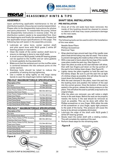
Figure A<br />
SHAFT SEAL<br />
Torque<br />
13.6 N•m (120 in-lbs)<br />
27.1 N•m (20 ft-lbs)<br />
108.5 N•m (80 ft-lbs)<br />
115.2 N•m (85 ft-lbs)<br />
74.6 N•m (55 ft-lbs)<br />
6.6 N•m (58 in-lbs)<br />
47.5 N•m (35 ft-lbs)<br />
47.5 N•m (35 ft-lbs)<br />
SHAFT SEAL INSTALLATION:<br />
PRE-INSTALLATION<br />
• Once all of the old seals have been removed, the<br />
inside of the bushing should be cleaned to ensure<br />
no debris is left that may cause premature damage<br />
to the new seals.<br />
INSTALLATION<br />
The following tools can be used to aid in the installation<br />
of the new seals:<br />
Needle Nose Pliers<br />
Phillips Screwdriver<br />
Electrical Tape<br />
• Wrap electrical tape around each leg of the needle nose<br />
pliers (heat shrink tubing may also be used). This is done<br />
to prevent damaging the inside surface of the new seal.<br />
• With a new seal in hand, place the two legs of the needle<br />
nose pliers inside the seal ring. (See Figure A.)<br />
• Open the pliers as wide as the seal diameter will allow,<br />
then with two fingers pull down on the top portion of<br />
the seal to form kidney bean shape. (See Figure B.)<br />
• Lightly clamp the pliers together to hold the seal into<br />
the kidney shape. Be sure to pull the seal into as tight<br />
of a kidney shape as possible, this will allow the seal to<br />
travel down the bushing bore easier.<br />
• With the seal clamped in the pliers, insert the seal into<br />
the bushing bore and position the bottom of the seal<br />
into the correct groove. Once the bottom of the seal is<br />
seated in the groove, release the clamp pressure on the<br />
pliers. This will allow the seal to partially snap back to its<br />
original shape.<br />
• After the pliers are removed, you will notice a slight<br />
bump in the seal shape. Before the seal can be properly<br />
resized, the bump in the seal should be removed as<br />
much as possible. This can be done with either the<br />
Phillips screwdriver or your finger. With either the side<br />
of the screwdriver or your finger, apply light pressure<br />
to the peak of the bump. This pressure will cause the<br />
bump to be almost <strong>com</strong>pletely eliminated.<br />
• Lubricate the edge of the shaft with NLGI grade 2<br />
white EP bearing grease.<br />
• Slowly insert the center shaft with a rotating motion.<br />
This will <strong>com</strong>plete the resizing of the seal.<br />
• Perform these steps for the remaining seals.<br />
Figure B<br />
NEEDLE NOSE<br />
PLIERS<br />
SHAFT SEAL<br />
TAPE<br />
TAPE<br />
WILDEN PUMP & ENGINEERING, LLC 20 WIL-10120-E-02