Concept study of radar sensors for near-field tsunami early warning
Concept study of radar sensors for near-field tsunami early warning
Concept study of radar sensors for near-field tsunami early warning

You also want an ePaper? Increase the reach of your titles
YUMPU automatically turns print PDFs into web optimized ePapers that Google loves.
1960 T. Börner et al.: <strong>Concept</strong> <strong>study</strong> <strong>of</strong> <strong>radar</strong> <strong>sensors</strong> <strong>for</strong> <strong>near</strong>-<strong>field</strong> <strong>tsunami</strong> <strong>early</strong> <strong>warning</strong><br />
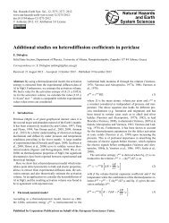
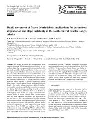
Fig. 1. Sketch <strong>of</strong> illumination geometry and spatial coverage.<br />
The <strong>for</strong>mulae above account <strong>for</strong> the geometric horizon (also<br />
called visual horizon). At microwave frequencies however,<br />
electromagnetic energy is bent slightly downwards. This<br />
phenomenon is such that the <strong>radar</strong> horizon is displaced farther<br />
away from the visual horizon. This effect can be taken<br />
into account by multiplying the earth radius by 4/3 (provided<br />
propagation occurs through a standard atmosphere) (Afullo<br />
et al., 2006). For a stratospheric airship located 20 km above<br />
ground, the <strong>radar</strong> horizon is thus located 575 km from the<br />
nadir point. So, considering the attitude change capabilities<br />
<strong>of</strong> the airship, the <strong>radar</strong> coverage <strong>for</strong> target detection is a<br />
disk <strong>of</strong> approximately 1000 km diameter. For the purpose <strong>of</strong><br />
<strong>tsunami</strong> detection however, we must be able to retrieve the<br />
RCS <strong>of</strong> the ocean itself, and not <strong>of</strong> a target on its surface.<br />
In the following section the per<strong>for</strong>mance prediction shows<br />
acceptable signal-to-noise ratio (SNR) even <strong>for</strong> −30 dB at<br />
incidence angles up to 85 ◦ (250 km ground range, 500 km diameter<br />
disk), but the variability <strong>of</strong> ocean surface <strong>radar</strong> cross<br />
section (RCS) at low grazing angles is such that the real monitoring<br />
capabilities <strong>of</strong> the system can only be ascertained by<br />
experimental measurements.<br />
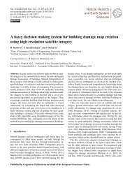
In the case <strong>of</strong> the Sunda trench (see Fig. 2), the length<br />
(3000 km) is such that an array <strong>of</strong> 4–5 airships is necessary<br />
to provide <strong>early</strong> <strong>warning</strong> to the entire Java and Sumatra coastline.<br />
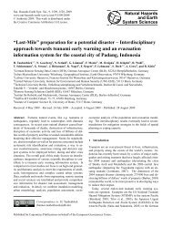
The same applies <strong>for</strong> the Mediterranean Sea (see Fig. 3),<br />
where almost every coastline lies in the <strong>near</strong>-<strong>field</strong>.<br />
There are however situations where fewer units could<br />
cover the whole <strong>tsunami</strong>genic areas <strong>of</strong> concern, providing<br />
<strong>near</strong>-<strong>field</strong> <strong>early</strong> <strong>warning</strong> to densely populated areas like<br />
Japan, the Cascadia Subduction Zone (CSZ) <strong>of</strong>f Oregon and<br />
British Columbia or the Philippines.<br />
3.2 RCS (<strong>radar</strong> cross section) mode<br />
For the RCS mode we present a per<strong>for</strong>mance prediction<br />
based on the single pulse <strong>radar</strong> equation, known in the literature<br />
as the SLAR <strong>radar</strong> equation (Henderson et al., 1998). In<br />
Fig. 2. Spatial coverage <strong>for</strong> Sunda trench and the Philippines.<br />
Fig. 3. Spatial coverage required <strong>for</strong> the Mediterranean Sea.<br />
remote sensing applications, in which the target is extended,<br />
it is appropriate to define σ 0 (normalized <strong>radar</strong> cross section)<br />
as the <strong>radar</strong> cross section per unit area <strong>of</strong> the scene as a random<br />
variable, with a mean σ 0, which in general varies from<br />
one resolution element to another. The following equation<br />
expresses the average SNR <strong>of</strong> a single <strong>radar</strong> pulse viewing an<br />
extended target with homogeneous mean specific backscatter<br />
coefficient σ 0.<br />
�<br />
PtG<br />
SNR=<br />
2λ2 (4π) 3R4 �� �<br />
1<br />
σ<br />
L<br />
0<br />
� �� �� �<br />
cτ λR 1<br />
(4)<br />
2sin(η) La kNTB<br />
where Pt is the transmitted power, G the antenna gain, R the<br />
range distance, La the antenna aperture, τ the pulse width,<br />
λ the <strong>radar</strong> signal wavelength, c the speed <strong>of</strong> light, N the<br />
noise figure, T the noise temperature, L the loss, and B is<br />
the Boltzmann constant.<br />
For oceanographic applications, the normalized <strong>radar</strong><br />
cross-section is strongly dependent on polarization (vertical<br />
VV or horizontal HH), angle <strong>of</strong> incidence, local wind speed<br />
and sea-state. For our per<strong>for</strong>mance prediction we will use<br />
indicative values. NESTRAD is meant to detect <strong>tsunami</strong>induced<br />
<strong>radar</strong> cross section modulations in the largest possible<br />
area. We will there<strong>for</strong>e consider incidence angles ranging<br />
Nat. Hazards Earth Syst. Sci., 10, 1957–1964, 2010 www.nat-hazards-earth-syst-sci.net/10/1957/2010/