Truck Troubleshooting Guide HALDEX MIDLAND CORPORATION ...
Truck Troubleshooting Guide HALDEX MIDLAND CORPORATION ...
Truck Troubleshooting Guide HALDEX MIDLAND CORPORATION ...

Create successful ePaper yourself
Turn your PDF publications into a flip-book with our unique Google optimized e-Paper software.
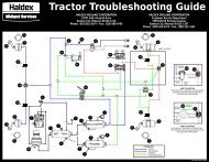
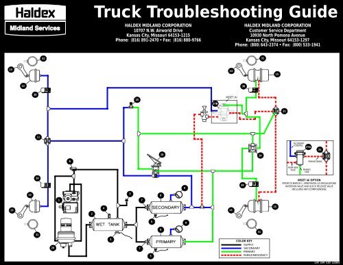
<strong>Truck</strong> <strong>Troubleshooting</strong> <strong>Guide</strong><br />
<strong>HALDEX</strong> <strong>MIDLAND</strong> <strong>CORPORATION</strong><br />
<strong>HALDEX</strong> <strong>MIDLAND</strong> <strong>CORPORATION</strong><br />
10707 N.W. Airworld Drive Customer Service Department<br />
Kansas City, Missouri 64153-1215<br />
10930 North Pomona Avenue<br />
Phone: (816) 891-2470 • Fax: (816) 880-9766 Kansas City, Missouri 64153-1297<br />
Phone: (800) 643-2374 • Fax: (800) 533-1941<br />
31<br />
31<br />
13<br />
13<br />
15<br />
12<br />
30<br />
30<br />
25<br />
27B<br />
INSET (A)<br />
21<br />
11<br />
SECONDARY<br />
CONTROL<br />
27A<br />
21<br />
10<br />
14<br />
6<br />
PARKING BRAKE<br />
FROM PARK<br />
VALVE<br />
PRIMARY<br />
TANK<br />
30<br />
9<br />
30<br />
INSET (A) OPTION<br />
PRIOR TO MARCH 1, 1998 FMVSS-121 REGULATIONS<br />
INVERSION VALVE AND QUICK RELEASE VALVE<br />
(INCLUDES ANTI-COMPOUNDING)<br />
12<br />
3<br />
8<br />
1<br />
7<br />
13<br />
2<br />
4<br />
13<br />
15<br />
5<br />
9<br />
31<br />
8<br />
31<br />
29<br />
5<br />
7<br />
5<br />
COLOR KEY<br />
SUPPLY<br />
SECONDARY<br />
PRIMARY<br />
PARK/EMERGENCY<br />
1/99 10M COV L20303
COMPLAINT/REMEDY COMPLAINT/REMEDY COMPLAINT/REMEDY COMPLAINT/REMEDY<br />
1<br />
2<br />
3<br />
4<br />
5<br />
5<br />
6<br />
COMPRESSOR<br />
PUMPS BEYOND “CUT-OUT”<br />
Check gauge.<br />
Check governor.<br />
Be certain it pressurizes unloader port when above “cut-out.”<br />
Check unloader/plungers. Lube, kit or change head.<br />
WON’T PUMP AIR<br />
Check gauge.<br />
Check compressor drive.<br />
Check inlet valves and plungers. If stuck, leak will be evident at intake<br />
when unloaded. Install unloader kit, head kit or head assembly.<br />
SLOW PRESSURE BUILD-UP<br />
Check gauge.<br />
Check compressor drive.<br />
Check intake for restriction.<br />
Check discharge line for restriction.<br />
Check unloader function. Lube or kit.<br />
Check inlet and exhaust valves. Leak will be evident at intake when unloaded.<br />
Kit or exchange head.<br />
PUMPS EXCESSIVE OIL<br />
Check oil return for restriction, kink or loop.<br />
Check for gasket sealant obstructing drain.<br />
Check for undersize return line (1/2” minimum).<br />
Check for fitting restricting drain.<br />
Check for intake vacuum (20” water maximum).<br />
Check for excessive engine crankcase pressure (poor engine ventilation).<br />
Check compressor ring wear. Exchange for service unit.<br />
WET TANK<br />
EXCESS OIL ACCUMULATION<br />
See PUMPS EXCESSIVE OIL (above).<br />
EXCESS WATER ACCUMULATION<br />
Drain daily. Install automatic drain on wet tank.<br />
DAMAGED WET TANK<br />
Replace.<br />
LOW PRESSURE INDICATOR SWITCH<br />
BUZZER OR LIGHT INOPERABLE<br />
Check ground and wiring on switch and buzzer/light.<br />
Replace switch or buzzer light.<br />
WON’T OPERATE AT PRESSURES BELOW 60 P.S.I.<br />
Check dash gauge for accuracy.<br />
Replace switch or buzzer light.<br />
SAFETY VALVE<br />
“POPS” OFF EXCESSIVELY<br />
Check system pressure.<br />
Valve operating properly in venting at 140/150 P.S.I.<br />
Check unloader/governor.<br />
“POPS” OFF AT LESS THAN 140 P.S.I.<br />
Replace.<br />
LEAKS<br />
Replace.<br />
WON’T FUNCTION<br />
Periodic Test: remove and test above 150 P.S.I. with shop air.<br />
Replace if non-functional.<br />
DRAIN VALVES - MANUAL<br />
LEAKS<br />
Replace.<br />
DRAIN VALVES - AUTOMATIC<br />
WON’T DRAIN<br />
Repair or replace.<br />
WON’T DRAIN IN COLD WEATHER<br />
Replace with heated unit.<br />
LEAKS - MALFUNCTIONS<br />
Repair or replace.<br />
Periodic Test: with system pressure stabilized (compressor unloaded) no<br />
leak evident at discharge port - make several foot brake applications to reduce<br />
wet tank pressure. Moisture should drain from discharge port.<br />
GOVERNOR<br />
FLUTTERS<br />
Check gauge.<br />
Check unloader line size (5/16” x 5’ maximum).<br />
Check air actuated accessory. Is the air volume requirement greater<br />
than governor capacity<br />
Check for plugged governor reservoir line.<br />
Repair, adjust or replace governor.<br />
WON’T PASS AIR TO UNLOADER TO “CUT-OUT”<br />
COMPRESSOR<br />
Check governor reservoir line..<br />
Repair or replace.<br />
7<br />
8<br />
9<br />
10<br />
11<br />
12<br />
13<br />
14<br />
SINGLE CHECK VALVE<br />
ALLOW BLEED BACK TO SUPPLY RESERVOIR<br />
Periodic Test: bleed supply reservoir and observe gauges. Check<br />
valves should maintain rear and front reservoir pressure.<br />
Replace if test results are negative.<br />
PRIMARY & SECONDARY RESERVOIR<br />
EXCESS OIL/WATER<br />
Drain as required.<br />
Check automatic drain valve on wet tank for proper operation (See #5).<br />
AIR GAUGE<br />
INCORRECT READING<br />
Calibrate or replace.<br />
DUAL SYSTEM FOOT BRAKE VALVE<br />
LEAKS AT EXHAUST WITH ALL BRAKES RELEASED<br />
Check anti-compound double check valve #21.<br />
Check #27a & 27b for back flow into service control line.<br />
CAUTION: CHOCK WHEELS - Repair and replace items as necessary.<br />
LEAKS AT EXHAUST WITH FOOT BRAKE APPLIED<br />
Foot valve defective. Repair or replace.<br />
LEAKS AT EXHAUST WITH ALL PARK BRAKES SET IN PARK POSITION AND<br />
FOOT BRAKE RELEASED<br />
Foot valve defective. Repair or replace.<br />
QUICK RELEASE VALVE<br />
LEAKS AT EXHAUST PORT WITH ALL BRAKES RELEASED<br />
Check and replace #27b if back flow occurs into service delivery line.<br />
LEAKS WHEN SERVICE BRAKES ARE APPLIED<br />
Repair or replace.<br />
SERVICE BRAKE CHAMBER<br />
LEAKS<br />
Replace diaphragm.<br />
Cage park brake.<br />
Reset clamps.<br />
Adjust brakes.<br />
WITH SERVICE BRAKES APPLIED<br />
STROKE IS AT OR BEYOND<br />
MAXIMUM LIMIT OF:<br />
Type 9 1 3/8”<br />
Type 12 1 3/8”<br />
Type 16 1 3/4”<br />
Type 20 1 3/4”<br />
Type 24 1 3/4”<br />
Type 30 2”<br />
SLUGGISH APPLICATION OR RELEASE<br />
Check basic brake.<br />
Check for air line restriction/leak.<br />
Align linkage.<br />
Check chamber return spring.<br />
Adjust brakes. Angle should approach 90° on application.<br />
Check for improper chamber or obstruction.<br />
90°<br />
Brake Released<br />
SLACK ADJUSTER<br />
SLEEVE WILL NOT DEPRESS<br />
Clean and lubricate or replace with unit dimensionally same.<br />
ADJUSTING SHAFT WILL NOT TURN<br />
Replace with unit dimensionally same.<br />
CRACKED HOUSING<br />
Check spring brake anti-compound system.<br />
Check air chamber size. Replace if larger than original size.<br />
Check direction of travel for proper position of hex nut (Shown Under #12).<br />
Hex nut must face away from chamber for uni-directional slack adjuster.<br />
WORN CLEVIS PIN BUSHING<br />
Replace bushing.<br />
RELAY VALVE<br />
LEAKS AT EXHAUST PORT WITH ALL BRAKES RELEASED<br />
Check seal in spring brake for back-flow of spring “hold-off” pressure<br />
through service port to open exhaust on valve. Replace #15 Spring Parking<br />
Brake.<br />
Check and replace #27b if back flow occurs into service delivery line.<br />
Check reservoir port for evidence of contamination, check supply lines for<br />
rusty fittings or carbon deposits. Repair or replace.<br />
LEAKS AT EXHAUST PORT WITH SERVICE BRAKES APPLIED<br />
Exhaust valve not seating properly. Repair or replace.<br />
15<br />
21<br />
25<br />
27a<br />
27b<br />
28<br />
29<br />
SPRING PARKING BRAKE (SERVICE ONLY<br />
SERVICE CHAMBER SIDE OF SPRING BRAKE)<br />
PARK BRAKE DRAGS OR WON’T RELEASE<br />
Check For: Improper adjustment, restriction or broken line. Diaphragm<br />
failure. System pressure too low. Improper manual release. Broken return<br />
spring (spring side). Quick release of relay malfunction. Broken power spring.<br />
Replace entire unit or piggy-back emergency section.<br />
SLUGGISH PARK APPLICATION<br />
Check For: Diaphragm failure. Improper manual release. Broken power spring.<br />
LEAKS WHEN PRESSURIZED FOR PARK BRAKE RELEASE<br />
Check For: Ruptured spring side diaphragm. Push rod seal leakage (may be<br />
evident at #14 relay valve).<br />
SERVICE CHAMBER MALFUNCTION<br />
See #12 service brake chamber.<br />
QUICK RELEASE AND DOUBLE CHECK VALVE<br />
COMBINATION<br />
FOOT VALVE EXHAUST LEAK PARK BRAKES RELEASED YELLOW DASH CONTROL V<br />
VALVE EXHAUST LEAK IN PARK POSITION AND SERVICE BRAKES APPLIED<br />
Check anti-compound double check valve portion for feedback to foot or dash<br />
control valve. Repair or replace.<br />
STOP LIGHT SWITCH<br />
LEAKS<br />
Replace.<br />
FAILS TO SIGNAL A GOOD BULB THROUGH SOUND WIRING AT 3-6 P.S.I.<br />
Replace.<br />
INVERSION RELAY VALVE WITH THE LOSS<br />
OF REAR SERVICE BRAKES, APPLICATION OF<br />
SPRING BRAKE BY USING THE EMERGENCY SEC-<br />
TION SHOULD BE AVAILABLE ALONG WITH FRONT<br />
SERVICE BRAKE BY APPLYING FOOT VALVE<br />
Periodically test by bleeding rear service tank and observing front brake and<br />
rear spring brake application upon depressing foot pedal. Repair or replace,<br />
if after checking piping is not functioning properly.<br />
LEAKS<br />
Repair or replace.<br />
BARRIER WHEEL OIL SEALS<br />
(NOT SHOWN IN SCHEMATIC)<br />
OIL LEAK<br />
Check for proper glazing of the sealing lip.<br />
Check serrations on O.D. and I.D. to see that sealing surfaces are dry.<br />
If wet, this could denote the leakage path.<br />
Check area between positioning pads. If wet, suspect seal leak.<br />
Check seal for possible damage incurred during installation.<br />
Check hub bore and spindle surfaces for imperfections or irregularities.<br />
Check to be sure that proper seal has been installed for the particular<br />
axle application.<br />
AIR DRYER<br />
AIR LEAKING CONSTANTLY FROM PURGE VALVE<br />
Purge valve seal damaged. Replace.<br />
Purge valve frozen.<br />
Inspect heater (see heater problems).<br />
HEATER INOPERATIVE<br />
Blown Fuse. Check fuse and replace with 8-10 amp fuse<br />
Broken wires or poor connections. Repair or replace wiring to heater.<br />
SLOW WET TANK BUILD-UP<br />
Filter and/or desiccant plugged. Service air dryer.<br />
30 ABS INLINE VALVES<br />
FOR COMPLETE TROUBLESHOOTING INFORMATION, REFER TO<br />
LITERATURE PIECES MODAL POWER TK-2 INSTALLATION & SERVICE MANUAL<br />
(L30022) AND/OR ABS DIAGNOSTIC TROUBLESHOOTING GUIDE (L20293)<br />
31 ABS SENSORS & EXCITER RINGS<br />
FOR COMPLETE TROUBLESHOOTING INFORMATION, REFER TO<br />
LITERATURE PIECES MODAL POWER TK-2 INSTALLATION & SERVICE MANUAL<br />
(L30022) AND/OR ABS DIAGNOSTIC TROUBLESHOOTING GUIDE (L20293)