
Create successful ePaper yourself
Turn your PDF publications into a flip-book with our unique Google optimized e-Paper software.
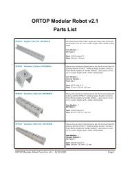
ORTOP Modular Robot v2.1<br />
Chassis <strong>Assembly</strong><br />
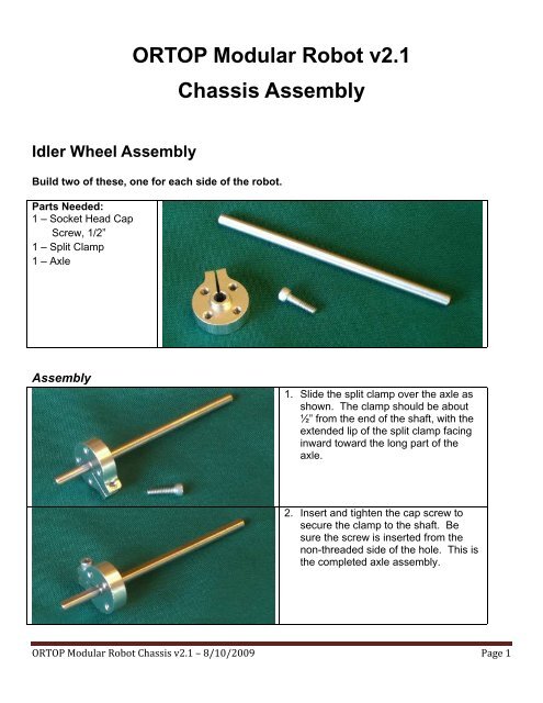
<strong>Idler</strong> <strong>Wheel</strong> <strong>Assembly</strong><br />
Build two of these, one for each side of the robot.<br />
Parts Needed:<br />
1 – Socket Head Cap<br />
Screw, 1/2”<br />
1 – Split Clamp<br />
1 – Axle<br />
<strong>Assembly</strong><br />
1. Slide the split clamp over the axle as<br />
shown. The clamp should be about<br />
½” from the end of the shaft, with the<br />
extended lip of the split clamp facing<br />
inward toward the long part of the<br />
axle.<br />
2. Insert and tighten the cap screw to<br />
secure the clamp to the shaft. Be<br />
sure the screw is inserted from the<br />
non-threaded side of the hole. This is<br />
the completed axle assembly.<br />
ORTOP Modular Robot Chassis v2.1 – 8/10/2009 Page 1
Parts Needed:<br />
4 – Socket Head Cap<br />
screw, 1/2”<br />
1 – 3” wheel<br />
1 – axle assembly<br />
<strong>Assembly</strong><br />
3. Slip the wheel over the axle assembly.<br />
4. Insert and tighten the four cap screws<br />
into the split clamp.<br />
ORTOP Modular Robot Chassis v2.1 – 8/10/2009 Page 2
Drive Motor <strong>Assembly</strong><br />
Build two of these, one for each side of the robot.<br />
Parts Needed:<br />
4 – Socket Head Cap<br />
Screw, 1/2”<br />
1 – 40 Tooth Gear<br />
1 – Motor Hub w/ Set<br />
Screw<br />
1 – DC Drive Motor<br />
<strong>Assembly</strong><br />
1. Insert the gear on to the motor hub<br />
with the flange on the hub facing into<br />
the gear.<br />
2. Attach with 4 cap screws.<br />
3. Slide the gear assembly onto the<br />
motor shaft abut 1/8” from the motor<br />
bushing.<br />
4. Tighten the motor hub set screw onto<br />
the flat part of the shaft.<br />
ORTOP Modular Robot Chassis v2.1 – 8/10/2009 Page 3
Drive <strong>Wheel</strong> <strong>Assembly</strong><br />
Build two of these, one for each side of the robot.<br />
Parts Needed:<br />
4 – Socket Head Cap Screw, 1-1/4”<br />
1 – 3” <strong>Wheel</strong><br />
1 – Gear Hub Spacer<br />
1 – 80 Tooth Gear<br />
1 – Split Clamp<br />
1 – Socket Head Cap Screw, 1/2”<br />
1 – Axle<br />
<strong>Assembly</strong><br />
1. Slide the split clamp over the axle as<br />
shown. The split clamp should be<br />
about 1-1/4” from the end of the<br />
shaft, with the extended lip of the split<br />
clamp facing outward towards the<br />
short end of the axle.<br />
2. Insert and tighten the screw to secure<br />
the split clamp to the shaft.<br />
ORTOP Modular Robot Chassis v2.1 – 8/10/2009 Page 4
3. Insert the 4 screws through the<br />
mounting holes on the wheel.<br />
4. Slide the gear hub spacer over the<br />
screws.<br />
5. Slide the 80-tooth gear over the<br />
screws.<br />
6. Slide the wheel assembly on the axle<br />
assembly.<br />
7. Tighten the 4 screws.<br />
ORTOP Modular Robot Chassis v2.1 – 8/10/2009 Page 5
Chassis Frame <strong>Assembly</strong><br />
Parts Needed:<br />
6 – Socket Head Cap Screws, 1/2”<br />
2 – Button Head Cap Screws, 3/8”<br />
8 – 6-32 Nuts<br />
2 – 288mm Channels<br />
2 – 288mm Flat Bars<br />
2 – 4” Lengths of Hook and Loop Fastener (Hook Part)<br />
<strong>Assembly</strong><br />
1. If the hook part of the hook and loop<br />
fasteners are not already attached to<br />
the channels, peel off the covering of<br />
the adhesive back of each strip and<br />
attach them to one end of each<br />
channel about 1-1/4 inch from the<br />
end. Do not cover the 8-hole rosette<br />
at the end of the channel.<br />
ORTOP Modular Robot Chassis v2.1 – 8/10/2009 Page 6
2. Attach the two flat bars to the top of<br />
the channel as shown. The two bars<br />
are exactly 8 large holes apart (5<br />
inches). The front bar will be<br />
centered on the front 8-hole rosette<br />
pattern.<br />
3. Use two screws at each intersection.<br />
4. Note that the left rear pair of screws<br />
are button head cap screws. The<br />
other six are socket head cap<br />
screws.<br />
5. Detail showing the left rear pair of<br />
screws.<br />
6. Finished chassis frame assembly<br />
showing which end is front.<br />
ORTOP Modular Robot Chassis v2.1 – 8/10/2009 Page 7
Mounting <strong>Idler</strong> <strong>Wheel</strong><br />
Mount two idler wheels, one on each side of the robot.<br />
Parts Needed:<br />
1 – <strong>Idler</strong> <strong>Wheel</strong> <strong>Assembly</strong><br />
1 – Bronze Bushing<br />
1 – Gear Hub Spacer<br />
1 – Axle Set Collar<br />
ORTOP Modular Robot Chassis v2.1 – 8/10/2009 Page 8
<strong>Assembly</strong><br />
1. Turn chassis upside down.<br />
2. Place the bushing in the inside of the<br />
side rail at the 5th hole from the rear<br />
of the chassis as shown<br />
3. Slide the wheel assembly through the<br />
hub spacer and then through the<br />
outside 5 th hole and through the<br />
bushing. Make sure the lip on the<br />
spacer goes into the big hole on the<br />
channel.<br />
4. Slide the collar over the end of the<br />
shaft.<br />
5. Tighten the set screw on the flat part<br />
of the shaft.<br />
ORTOP Modular Robot Chassis v2.1 – 8/10/2009 Page 9
Installing Drive <strong>Wheel</strong>s and Motor Mounts<br />
Install two of these sets, one for each side of the robot.<br />
Parts Needed:<br />
1 – Motor mount<br />
1 – Socket Head Cap<br />
Screw, 1-1/2”<br />
1 – Socket Head Cap<br />
Screw, 1-1/4”<br />
2 – 6-32 Nuts<br />
<strong>Assembly</strong><br />
1. Locate the two holes as indicated.<br />
The split end of each motor mount<br />
faces the front of the robot.<br />
2. Place the motor mount on the<br />
channel and insert the longer<br />
screw in the front (split) end of the<br />
mount and the shorter screw in the<br />
back.<br />
3. Attach nuts to each screw and<br />
securely tighten the back screw<br />
(the shorter one).<br />
4. Leave the nut on the front screw<br />
loose for now.<br />
ORTOP Modular Robot Chassis v2.1 – 8/10/2009 Page 10
Parts Needed:<br />
1 – Drive <strong>Wheel</strong><br />
<strong>Assembly</strong><br />
2 – Bushings<br />
1 – Axle Set Collar<br />
Chassis Frame <strong>Assembly</strong><br />
<strong>Assembly</strong><br />
1. Turn chassis upside down.<br />
2. Place the bushings in the channels at<br />
the 3rd hole from the front of the<br />
chassis (as indicated above). The<br />
bushings are inserted with the narrow<br />
end inside the channel.<br />
3. Insert the drive wheel assembly into<br />
the bushings from the outside. Make<br />
sure the bushings seat firmly against<br />
the channel sides.<br />
ORTOP Modular Robot Chassis v2.1 – 8/10/2009 Page 11
4. Slide the collar over the end of the axle<br />
from inside the robot.<br />
5. Tighten the set screw on the flat part of<br />
the axle.<br />
Final <strong>Assembly</strong><br />
Parts Needed:<br />
2 – Motor Assemblies<br />
1 – Chassis Frame<br />
<strong>Assembly</strong><br />
ORTOP Modular Robot Chassis v2.1 – 8/10/2009 Page 12
<strong>Assembly</strong><br />
1. Slide the motor, gear end first,<br />
through the motor mount from the<br />
inside and work the motor head<br />
into the mount. The motor mount<br />
screw at the split end must be<br />
loose for this to work.<br />
2. Push the motor through until the<br />
front of the motor is flush with the<br />
mount. You may need to loosen<br />
the set screw on the motor hub to<br />
move the small gear in or out to<br />
ensure that 100% of the thickness<br />
of the small gear meshes with the<br />
large gear. Retighten the set<br />
screw.<br />
3. Rotate the motor in motor mount<br />
so that the gears mesh. See<br />
diagram below for proper gear<br />
meshing technique.<br />
4. Tighten the screw in the split part<br />
of the motor mount to secure the<br />
motor.<br />
Proper Gear Meshing<br />
Too Loose Just Right Too Tight<br />
ORTOP Modular Robot Chassis v2.1 – 8/10/2009 Page 13
Completed Chassis <strong>Assembly</strong><br />
ORTOP Modular Robot Chassis v2.1 – 8/10/2009 Page 14