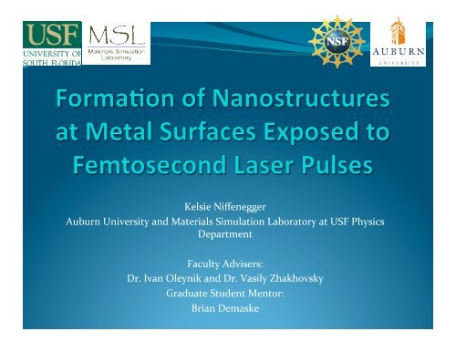
Kelsie Niffenegger, Brian Demaske, Vasily Zhakhovsky and Ivan ...
Kelsie Niffenegger, Brian Demaske, Vasily Zhakhovsky and Ivan ...
Kelsie Niffenegger, Brian Demaske, Vasily Zhakhovsky and Ivan ...

Create successful ePaper yourself
Turn your PDF publications into a flip-book with our unique Google optimized e-Paper software.
<strong>Kelsie</strong> <strong>Niffenegger</strong> <br />
Auburn University <strong>and</strong> Materials Simulation Laboratory at USF Physics <br />
Department <br />
Faculty Advisers: <br />
Dr. <strong>Ivan</strong> Oleynik <strong>and</strong> Dr. <strong>Vasily</strong> <strong>Zhakhovsky</strong> <br />
Graduate Student Mentor: <br />
<strong>Brian</strong> <strong>Demaske</strong>
Background Informa/on <br />
Femtosecond laser for formation of <br />
nanostructures <br />
<br />
<br />
Ultrashort heating of electrons (10 15 K/s) <br />
Heating depth very small (~100 nm) <br />
Response of metals to ultrafast energy <br />
deposition <br />
<br />
<br />
<br />
<br />
<br />
Build‐up of high pressure in surface layer <br />
Formation & propagation of ultrashort <br />
pressure waves <br />
Strong tensile wave results in cavitation <br />
Ablation & surface morphology <br />
Ultrafast cooling (10 12 K/s)
Pump Probe Technique <br />
Typical experimental set-up:<br />
Ti-Sapphire laser system<br />
• λ ~ 800 nm<br />
• center ~ 45°<br />
• t pulse ~ 100 fs<br />
• F incident < 1 J/cm 2<br />
Ablation threshold:<br />
F absorbed ≈ 100 - 200 mJ/cm 2<br />
pump pulse<br />
probe pulse<br />
sample<br />
Crater depth at threshold:<br />
d crater ≈ 110 - 130 nm<br />
probe
Experimental Analysis <br />
a<br />
.<br />
b.<br />
c.<br />
Cross sections of Al <br />
film after ultrashort <br />
laser irradiation show <br />
that there are bubbles <br />
frozen underneath the <br />
material next to the <br />
formed crater. <br />
Experiments done by S. Ashitkov at Institute for High Temperatures, RAS<br />
Images obtained by Y. Emirov at USF Nanoscience Research <strong>and</strong> Education Center
What are we trying to do <br />
Gain an atomic scale underst<strong>and</strong>ing of mechanisms that <br />
cause surface modification <br />
Want to show the formation <br />
of a crater with frozen <br />
bubbles under the surface <br />
of an irradiated gold film <br />
• Past simulations of ablation were done with 1D heating –<br />
didn’t allow for generation of 2D or 3D nanostructures, <br />
ours simulates a 2D energy distribution on the surface <br />
allowing us to make those structures <br />
• 2 parts of modeling: <br />
• 2 temperature (ions & electrons) for short time <br />
• Then, 1 temperature (ions) for long time
Two Temperature Model <br />
~10 nm<br />
1.Transmission of energy from <br />
laser pulse to conduction <br />
electrons within surface layer <br />
2.Transport of heat by electrons <br />
through Au target <br />
3.Exchange of energy between <br />
electron <strong>and</strong> ion subsystems <br />
until thermal equilibrium is <br />
established <br />
laser pulse <br />
conduction<br />
electrons<br />
Fit shape to functional form<br />
<strong>and</strong> use as initial profile for 1-<br />
temperature regime<br />
(MD simulation)
Molecular Dynamics (MD) method <br />
z <br />
periodic<br />
boundary<br />
conditions<br />
reflection y <br />
x <br />
pump pulse<br />
<br />
<br />
<br />
MD method is based on tracking of the atom motions by numerical solving <br />
of Newton’s equations. <br />
Periodical boundary conditions are imposed on the system along y,z – axes, <br />
with free boundary conditions on the x‐axis. <br />
Laser heating is non‐uniform in x‐y plane, <strong>and</strong> results in a given profile <br />
T 0 (x,y) = T 0 (x)* cos 8 ( ).
3 Main Processes: Mel/ng, JeJng <strong>and</strong> Cavia/on <br />
a. b. c.<br />
Laser induced melting is shown in image “a” with a <br />
small amount of energy put into the system <br />
Jetting of the material occurred when more energy was <br />
added, as in image “b” <br />
Cavitation under a cupola, image “c”, requires even <br />
more energy to cause significant expansion of the <br />
liquid surface
Abla/on of gold film by non‐uniform laser beam <br />
Parameters of movie simulation…<br />
5,000 K with material size 160 x 600 x 10 [nm]
Mechanisms of crater forma/on <br />
The combination of <br />
these three processes <br />
followed by recrystallization (cooling) <br />
results in the final <br />
morphology which <br />
includes the crater <strong>and</strong> <br />
frozen bubbles. <br />
density<br />
velocity
Conclusions <br />
The major processes leading to the formation of the <br />
surface morphology were investigated by MD <br />
Non‐uniform energy distribution in laser beam <br />
induce: <br />
<br />
<br />
<br />
<br />
<br />
Fast melting of thin surface layer <br />
Jetting of molten material <br />
Cavitation under a liquid shell <br />
Cupola formation followed by its breaking <br />
Slow recrystallization of liquid surface layer <br />
<br />
Qualitative agreement with experiment found
Acknowledgments <br />
This research is supported by <br />
<br />
NSF REU program in Computational Materials <br />
Science (grant # DMR‐0755256) <br />
<br />
NSF grant # DMR‐1008676