Gyrodometry: A New Method for Combining ... - Valentiniweb.com
Gyrodometry: A New Method for Combining ... - Valentiniweb.com
Gyrodometry: A New Method for Combining ... - Valentiniweb.com

You also want an ePaper? Increase the reach of your titles
YUMPU automatically turns print PDFs into web optimized ePapers that Google loves.
Proceedings of the 1996 IEEE International Conference on Robotics and Automation, Minneapolis, Apr. 22-28, 1996, pp. 423-428.<br />
<strong>Gyrodometry</strong>: A <strong>New</strong> <strong>Method</strong> <strong>for</strong> <strong>Combining</strong> Data<br />
from Gyros and Odometry in Mobile Robots<br />
by<br />
J. Borenstein and L. Feng<br />
The University of Michigan<br />
Advanced Technologies Lab, 1101 Beal Ave.<br />
Ann Arbor, MI 48109-2110<br />
Email: johannb@umich.edu and Feng@engin.umich.edu<br />
ABSTRACT<br />
This paper presents a very simple, yet very effective<br />
method <strong>for</strong> <strong>com</strong>bining measurements from a gyro<br />
with measurements from wheel encoders (odometry).<br />
Sensor-fusion of this kind has been done be<strong>for</strong>e, usually<br />
by means of a statistical model that describes the<br />
behavior of the gyro and the behavior of the odometry<br />
<strong>com</strong>ponent. However, because these systems are based<br />
on models, they cannot anticipate the unpredictable<br />
and potentially "catastrophic" effect of larger bumps or<br />
objects occasionally encountered on the floor.<br />
By contrast, our method, called <strong>Gyrodometry</strong>, has<br />
been developed based on a careful study of the physical<br />
interaction between the ground and the vehicle. We<br />
present experimental evidence that non-systematic<br />
odometry error sources (such as bumps) impact the<br />
vehicle only during very short periods; typically a<br />
fraction of a second <strong>for</strong> each encounter. During these<br />
short instances the readings from the gyro and from<br />
odometry differ significantly, while in the absence of<br />
large non-systematic errors the readings are very<br />
similar. <strong>Gyrodometry</strong> makes use of this observation by<br />
using odometry data only C most of the time, while<br />
substituting gyro data only during those brief instances<br />
during which gyro and odometry data differ substantially.<br />
This way the ill-effects of gyro drift are almost<br />
<strong>com</strong>pletely eliminated, and our method can thus make<br />
use of inexpensive gyros with large drift rates. Experimental<br />
data is presented that demonstrates the<br />
effectiveness of this approach.<br />
1. INTRODUCTION AND BACKGROUND<br />
In most mobile robot applications two basic position-estimation<br />
methods are employed together: absolute<br />
and relative positioning [Byrne et al., 1992;<br />
Chenavier and Crowley, 1992; Evans, 1994]. Absolute<br />
positioning methods usually rely on navigation beacons,<br />
active or passive landmarks, map matching, or<br />
satellite-based navigation signals. Each of these absolute<br />
positioning approaches can be implemented by a<br />
variety of methods and sensors. Yet, none of the currently<br />
existing systems is particularly elegant, and<br />
usually these systems are somewhat expensive. A<br />
<strong>com</strong>prehensive survey on mobile robot positioning<br />
methods is given in [Borenstein et al., 1995].<br />
Relative positioning is usually based on odometry.<br />
Odometry is simple, inexpensive, and easy to ac<strong>com</strong>plish<br />
in real-time. The disadvantage of odometry is its<br />
unbounded accumulation of errors.<br />
With the introduction of optical fiber gyros the use<br />
of gyros has be<strong>com</strong>e more attractive <strong>for</strong> mobile robot<br />
applications. However, gyros have relatively large drift<br />
rates, which cause unbounded growth in orientation<br />
errors.<br />
Because of their potential <strong>for</strong> unbounded growth of<br />
errors, odometry and gyros can only be used in conjunction<br />
with periodic absolute position updates.<br />
Nonetheless, improving odometry and gyro accuracy<br />
helps increase the travel distance in-between absolute<br />
position updates, and thus results in lower installation<br />
and operating costs <strong>for</strong> the whole system.<br />
D:\WP\PAPERS\P63b.doc, Thursday,June 27,1996
1.1 Properties of odometry errors<br />
In this section we discuss properties of odometry as<br />
they relate to differential-drive vehicles (i.e., vehicles<br />
that have two independently driven wheels). Optical<br />
encoders are typically mounted on the drive motors to<br />
count the wheel revolutions. Using simple geometric<br />
equations, it is straight-<strong>for</strong>ward to <strong>com</strong>pute the momentary<br />
position of the vehicle relative to a known<br />
starting position. This <strong>com</strong>putation is called odometry.<br />
It is important to note that when considering errors in<br />
odometry, orientation errors are the main source of<br />
concern. This is so because once incurred, orientation<br />
errors grow without bound into lateral position errors<br />
[Feng et al., 1993].<br />
Odometry is based on the assumption that wheel<br />
revolutions can be translated into linear displacement<br />
relative to the floor. This assumption is only of limited<br />
validity. One extreme example is wheel slippage: if<br />
one wheel was to slip on, say, an oil spill, then the<br />
associated encoder would register wheel revolutions<br />
even though these revolutions would not correspond to<br />
a linear displacement of the wheel.<br />
Besides this extreme case of total slippage, there<br />
are several other, more subtle reasons <strong>for</strong> inaccuracies<br />
in the translation of wheel encoder readings into linear<br />
motion. All of these error sources fit into one of two<br />
categories: (1) systematic errors and (2) nonsystematic<br />
errors.<br />
1. Systematic errors<br />
a. Unequal wheel diameters<br />
b. Average of both wheel diameters differs from<br />
nominal diameter<br />
c. Misalignment of wheels<br />
d. Uncertainty about the effective wheelbase (due to<br />
non-point wheel contact with the floor)<br />
e. Limited encoder resolution<br />
f. Limited encoder sampling rate<br />
2. Non-systematic errors<br />
a. Travel over uneven floors<br />
b. Travel over unexpected objects on the floor<br />
c. Wheel-slippage<br />
In recent work we introduced "UMBmark," a<br />
method <strong>for</strong> measuring and correcting systematic<br />
odometry errors in differential-drive mobile robots<br />
[Borenstein and Feng, 1995a; 1995b]. With this<br />
method we were able to reduce the systematic odometry<br />
error of an uncalibrated LabMate robot [TRC] by<br />
one order of magnitude. However, this measure alone<br />
cannot guarantee trouble-free odometry, because occasional<br />
bumps, cracks or other large disturbances can<br />
cause unpredictable "catastrophic" odometry errors<br />
that can easily lead to the <strong>com</strong>plete failure of the robot's<br />
mission. The method presented in this paper is<br />
designed to detect and correct such "catastrophic" nonsystematic<br />
odometry errors.<br />
1.2 The use of gyros in mobile robot applications<br />
An extensive study of the use of gyroscopes in mobile<br />
robots was conducted by [Barshan and Durrant-<br />
Whyte, 1995]. One of the tested instruments was the<br />
ENV-O5S Gyrostar from [MURATA] and the other<br />
was the Solid State Angular Rate Transducer (START)<br />
gyroscope manufactured by [GEC]. Barshan and Durrant-Whyte<br />
evaluated the per<strong>for</strong>mance of these two<br />
gyros and found that they suffered relatively large<br />
drift, on the order of 5 to 15E/min. The Ox<strong>for</strong>d researchers<br />
then developed a sophisticated error model<br />
<strong>for</strong> the gyros, which was subsequently used in an Extended<br />
Kalman Filter (EKF). At the end of a 5-minute<br />
experiment, the START had accumulated a heading<br />
error of -70.8E while the error of the Gyrostar was<br />
-59E. With the EKF, the accumulated errors were<br />
much smaller: 12E was the maximum heading error<br />
<strong>for</strong> the START gyro, while that of the Gyrostar was -<br />
3.8E. Overall, the results from applying the EKF show<br />
a 5 to 6-fold reduction in the angular measurement<br />
after a five-minute test period. However, even with the<br />
EKF, a drift rate of 1 to 3 o /min can still be expected.<br />
Komoriya and Oyama [1994] conducted a study of<br />
a system that used the OFG-3 [HITACHI] optical fiber<br />
gyroscope in conjunction with odometry in<strong>for</strong>mation.<br />
This fusion of in<strong>for</strong>mation from these two different<br />
sensor systems was realized through a Kalman Filter.<br />
Komoriya and Oyama tested their method in actual<br />
experiments with a mobile robot. In one set of experiments<br />
their robot was instructed to follow a triangular<br />
path of 5 m total length. The robot's maximum speed<br />
was 0.14 m/s and that speed was further reduced at the<br />
corners of the path. The results of this experiment indicate<br />
an average position error of about 5 mm. However,<br />
it is not immediately evident how this error was<br />
found. We interpret the quoted results as showing a<br />
position error that was <strong>com</strong>puted by the onboard <strong>com</strong>puter,<br />
but not measured absolutely.<br />
In both of the above studies a Kalman Filter approach<br />
was taken to reduce the drift and to fuse<br />
odometry and gyro data. Kalman filters require a detailed<br />
model of the sensors and the interaction between<br />
the wheels and the floor (i.e., odometry). To model<br />
2
odometry researchers typically define "error ellipsis"<br />
that describe the probability of the robot to be indeed<br />
at the location its odometry has determined. These<br />
models are usually based on the robot's systematic errors,<br />
but they cannot take into account non-systematic<br />
errors and especially "catastrophic" events like the<br />
encounter of a bump, crack, or other irregularity of the<br />
floor.<br />
To over<strong>com</strong>e this problem, we took a different approach.<br />
We studied the physical interaction between<br />
the floor and the wheels during "catastrophic" events.<br />
We present relevant results of this study in Section 2.<br />
Based on these results we developed <strong>Gyrodometry</strong>, a<br />
method <strong>for</strong> improving odometric accuracy with gyros<br />
regardless of the gyro's drift rate (see Section 3). Section<br />
4 presents initial experimental results from implementing<br />
<strong>Gyrodometry</strong> on a LabMate robot.<br />
In the experiments described in the following sections<br />
we used the Murata Gyrostar [Murata] model<br />
ENV-05H (see Fig. 1). The Gyrostar is a piezoelectric<br />
vibrating gyroscope with analog voltage output that<br />
varies linearly with the measured rate of rotation. connection<br />
to a <strong>com</strong>puter. The drift rate we measured in<br />
practice was 3 to 15E/min (similar to the drift observed<br />
by [Barshan and Durrant-Whyte, 1995] <strong>for</strong><br />
their Gyrostar sensor). We will assume an average<br />
drift rate of 10E/min = 0.166E/s. A detailed discussion<br />
of gyroscopes <strong>for</strong> mobile robot applications is given in<br />
[Borenstein et al., 1996].<br />
Figure 1: The Murata Gyrostar ENV-05H was used in<br />
the experiments in this paper.<br />
2. ANALYSIS<br />
When the left wheel (W L ) of a differential-drive robot<br />
like the LabMate travels over a bump (or crack, or<br />
other irregularity), then W L 's total travel distance<br />
would have to increase by an amount )D if the robot<br />
was to maintain straight-line motion. )D is a function<br />
of the wheel diameter and the height of the bump (see<br />
[Borenstein, 1995] <strong>for</strong> a detailed analysis). However,<br />
<strong>for</strong> straight-line motion the low-level controller of a<br />
conventional differential-drive mobile robot will try to<br />
keep the rotational velocities of both wheels equal.<br />
Thus, the horizontal distance traveled by W L will be<br />
)D less than that of W R , causing a curved motion into<br />
the direction of the bump. After traversing the bump,<br />
the vehicle will continue in straight-line motion, but<br />
with a constant orientation error )2 bump , given by<br />
)2 bump – )D/b, where b is the wheelbase of the robot.<br />
One further effect that is noticeable while traversing<br />
a bump is that the vehicle will first turn toward the<br />
bump, then away from it. This is so because the wheel<br />
that encounters the bump (W L ) slows down momentarily<br />
as some of the kinetic energy from the <strong>for</strong>ward motion<br />
is converted into potential energy associated with<br />
the higher elevation of the vehicle on top of the bump.<br />
Then, when the robot rolls off the bump, it regains its<br />
velocity and turns back (almost) to its original orientation.<br />
The wheel encoders are aware of the change in<br />
velocity and will provide correct data on the event.<br />
However, the wheel encoders are not aware that W L<br />
traveled the extra distance )D. Because of this, the<br />
robot does not turn back <strong>com</strong>pletely in the original<br />
direction of motion, thereby establishing the constant<br />
orientation error )2 bump described above.<br />
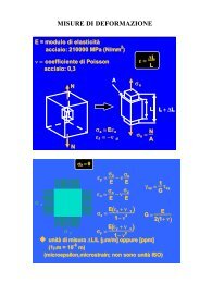
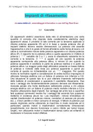
Figure 2 provides experimental data in support of<br />
the above model. In the experiment of Fig. 2 a Lab-<br />
Mate robot traveled at a slow speed of 10 cm/s on a<br />
smooth concrete floor. The custom-built motor controller<br />
that we installed on that vehicle uses a so-called<br />
cross-coupling control algorithm [Feng et al., 1993]<br />
that tries to maintain equal encoder pulses from both<br />
wheels at all times. The vehicle ran <strong>for</strong> 140 s (.14 m)<br />
and artificial bumps (see Table I) were introduced by<br />
placing pieces of different-diameter household extension<br />
cables under the right wheel at roughly 1-m intervals.<br />
The momentary orientation of the vehicle based on<br />
odometry is plotted and labeled 2 odo in Fig. 2. Since<br />
the odometry <strong>com</strong>putation is unaware of the error D,<br />
the bumps cause only a short swerve <strong>for</strong> each encounter,<br />
but the vehicle returns to it original orientation (at<br />
least, that's what the odometry algorithm "thinks").<br />
3
The momentary orientation<br />
of the robot as measured with<br />
the Gyrostar is plotted and labeled<br />
gyro in Fig. 2. The magnitude<br />
of the swerve as measured<br />
by the gyro is similar to<br />
that measured by odometry.<br />
However, the gyro-plot shows<br />
that after each swerve there is a<br />
clearly discernible residual increment<br />
in the orientation of<br />
the vehicle, on the order of 0.5 o<br />
- 0.8 o <strong>for</strong> the larger bumps.<br />
Since the odometry <strong>com</strong>putation<br />
is unaware of the error<br />
)D, the bumps cause only a<br />
short swerve <strong>for</strong> each encounter,<br />
but the vehicle returns to it<br />
original orientation (at least,<br />
that's what the odometry algorithm<br />
"thinks").<br />
The momentary orientation<br />
of the robot as measured with the Gyrostar is plotted<br />
and labeled 2 gyro in Fig. 2.<br />
While Fig. 2 explains some of the physical aspects<br />
of the robot's encounter with bumps, the figure does<br />
not provide in<strong>for</strong>mation on the accuracy of the gyro<br />
data. For example, we cannot tell the actual drift of the<br />
gyro from examining Fig. 2. An absolute measure of<br />
the robot's momentary orientation is needed, against<br />
which the gyro-data can be plotted. To obtain such an<br />
absolute measure we installed a simple wall-following<br />
system, based on two sideways facing Polaroid ultrasonic<br />
sensors. Then, when traveling along a continuous,<br />
straight wall, it is possible to measure the absolute<br />
orientation of the robot to within typically "0.25 o . The<br />
momentary orientation of the robot, according to the<br />
sonar wall-following sensor, is shown and labeled<br />
2 sonar in Fig. 2. According to the sonars, at the end of<br />
this run the accumulated orientation error is -9 o . One<br />
can also see now that the gyro readings were off by<br />
approximately 4.2 o at the end of the run. We attribute<br />
this discrepancy to the drift rate of the gyro; here about<br />
4.2 o /140 s = 0.03 o /s = 1.8 o /min.<br />
Measured orientation [deg]<br />
1<br />
0<br />
0<br />
-1<br />
10 20 30 40 50 60 70 80 90 100 110 120 130 140<br />
-2<br />
-3<br />
-4<br />
-5<br />
-6<br />
-7<br />
-8<br />
-9<br />
-10<br />
-11<br />
-12<br />
-13<br />
paper63.xls, paper63..ppt, gyro22.wmf<br />
Table 1: Objects used to create the bumps in Fig. 2<br />
Bumps 1-5 Bumps 6-10 Bumps 11-15<br />
time [sec]<br />
θ odo<br />
θ sonar<br />
θ gyro<br />
Figure 2: Momentary orientation of the robot as measured by odometry (θ odo),<br />
the Gyrostar (θ gyro), and the "<strong>com</strong>pletely accurate" wall-following sonars (θ sonar).<br />
During this 2:20-minute run at 10 cm/s, the robot encountered 15 bumps of different<br />
heights under its right wheel.<br />
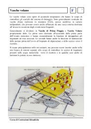
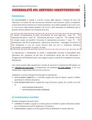
The effect of a single bump on the robot's sensors<br />
is shown in Fig. 3. The plot shows the change in orientation<br />
of the robot per sampling interval, as measured<br />
by odometry ()2 odo ) and by the gyro ()2 gyro ). The<br />
experiment is similar to that of Fig. 2, except that the<br />
data <strong>for</strong> Fig. 3 came from an earlier test with a different<br />
gyro and a single bump was encountered by the left<br />
wheel, at t = 73 s. The sampling interval in this experiment<br />
was T = 0.1 s.<br />
Figure 3 shows how the vehicle first turns toward<br />
the bump (ccw, positive portion of the curve) while the<br />
affected wheel climbs up the bump, then away from<br />
the bump (cw), while the affected wheel rolls off the<br />
bump. Since the robot controller is set up to maintain<br />
equal encoder pulse counts, the robot steers back to its<br />
"original" direction after traversing the bump. However,<br />
since odometry missed some of the initial turning,<br />
the robot does not <strong>com</strong>pletely turn back to its<br />
original orientation and thus retains a large residual<br />
orientation error.<br />
We interpret the gyro-measured change of orientation,<br />
)2 gyro, as an almost accurate representation of the<br />
actual rotation per<strong>for</strong>med by the vehicle. We do so<br />
because the typical drift rate of the Gyrostar (0.03 o /s)<br />
is negligible when <strong>com</strong>pared to the peak rate of rotation,<br />
which is reached at t = 72.9 s and which amounts<br />
to 0.7 o /0.1s = 7 o /s. Based on these values, the drift rate<br />
of the Gyrostar (we assumed an average drift of<br />
0.166E/s in Section 1) introduces an acceptable inaccuracy<br />
of 0.166/7 . 2.37% <strong>com</strong>pared to the peak rate.<br />
6-mm dia.<br />
cable<br />
9-mm dia.<br />
Cable<br />
12-mm dia<br />
cable<br />
4
3. GYRODOMETRY<br />
In this section we introduce <strong>Gyrodometry</strong> C a<br />
new method <strong>for</strong> fusing data from a gyro with data obtained<br />
from odometry. As we explained in Section 1,<br />
one of the most serious problems with odometry is the<br />
potential <strong>for</strong> "catastrophic" non-systematic errors, such<br />
as those caused by bumps or other large irregularities<br />
on the ground. We also argued that the robot cannot be<br />
calibrated to <strong>com</strong>pensate <strong>for</strong> non-systematic errors, nor<br />
that is it possible to predict the frequency or magnitude<br />
of these errors. Similarly, we recalled that the<br />
<strong>for</strong>emost problem with gyros is their inherent drift,<br />
which results in continuous and unbounded growth of<br />
the orientation error. <strong>Gyrodometry</strong> reduces the illeffects<br />
of these problems.<br />
The <strong>Gyrodometry</strong> method is based on the hypothesis<br />
that the discrepancy between the odometry curve<br />
and the gyro curve persists only over a very short<br />
amount of time. The experimental data in Fig. 3 lends<br />
credence to this hypothesis, as can be seen by investigating<br />
the line labeled )2 gyro - )2 odo in Fig. 3. This<br />
line shows the difference between the odometry and<br />
the gyro measurements, defined as<br />
) G-O = )2 gyro - )2 odo .<br />
The <strong>Gyrodometry</strong> method now simply <strong>com</strong>pares<br />
) G-O to a preset threshold, <strong>for</strong> example<br />
0.8<br />
0.7<br />
0.6<br />
0.5<br />
0.4<br />
0.3<br />
0.2<br />
0.1<br />
0.0<br />
-0.1<br />
-0.2<br />
-0.3<br />
-0.4<br />
-0.5<br />
-0.6<br />
-0.7<br />
-0.8<br />
Measured ∆θ/T (deg/0.1 s)<br />
∆θodo<br />
∆θgyro<br />
∆θ<br />
gyro<br />
- ∆θ<br />
odo<br />
72 73 74 75 76 77<br />
g950913a.xls, gyro30.cdr, gyro30.wmf, 9/17/95<br />
Figure 3: Effect of a single bump on the vehicle's<br />
change of orientation per sampling interval, as measured<br />
by odometry and by the gyro. The bump was a<br />
9-mm dia. cable placed under the left wheel.<br />
t (s)<br />
)2 thres = 0.125 o /T. Then, if |) G-O | > )2 thres , the<br />
robot's momentary orientation 2 i is <strong>com</strong>puted<br />
based on )2 gyro ; if |) G-O | < )2 thres , then 2 i is <strong>com</strong>puted<br />
based on )2 odo . The <strong>com</strong>plete implementation of the<br />
<strong>Gyrodometry</strong> method can thus be expressed by this<br />
simple pseudo-code statement:<br />
if (|) G-O,i | > )2 thres )<br />
then<br />
else<br />
2 i = 2 i-1 + )2 gyro,i T<br />
2 i = 2 i-1 + )2 odo,i T<br />
One can see in Fig. 3 that |θ G-O |> thres is true <strong>for</strong><br />
only three sampling intervals (=0.3 s). Yet, this short<br />
amount of time accounts <strong>for</strong> most of the difference<br />
between θ gyro and θ odo . Consequently, the robot's<br />
dead-reckoning systems relies on the gyro data only<br />
<strong>for</strong> a small fraction of the total travel time, keeping the<br />
system largely free of the drift associated with the gyroscope.<br />
On the other hand, the gyro data covers those<br />
intervals in which the odometry error would have been<br />
largest. The effectiveness of the <strong>Gyrodometry</strong> method<br />
is illustrated by experimental results presented in the<br />
next section.<br />
In this section we present experimental results that<br />
illustrate the effectiveness of the <strong>Gyrodometry</strong> method.<br />
For the sake of consistency, we have used the same set<br />
of experimental data that was used in Figure 2 <strong>for</strong> Figure<br />
4 in this section. One should note, though, that we<br />
have actually conducted many experimental runs C all<br />
with similarly good results as those shown here.<br />
Be<strong>for</strong>e we present the experimental results we have<br />
to define the following orientation errors (recall that<br />
we consider the sonar-based orientation measurements<br />
as "<strong>com</strong>pletely correct").<br />
, odo = 2 odo - 2 sonar (2a)<br />
, gyro = 2 gyro - 2 sonar (2b)<br />
, go = 2 go - 2 sonar (2c)<br />
where<br />
2 odo , 2 gyro , 2 sonar , 2 go C Momentary orientation as<br />
<strong>com</strong>puted by odometry, the gyro, the sonars, and the<br />
<strong>Gyrodometry</strong> method, respectively.<br />
, odo , , gyro , , go C Momentary orientation error as<br />
<strong>com</strong>puted by odometry, the gyro, and the <strong>Gyrodometry</strong><br />
method, respectively.<br />
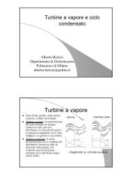
Although the experimental data used in Fig. 4 is<br />
identical to the data used <strong>for</strong> Fig. 2, Fig. 4 differs in<br />
that it shows a plot of the orientation errors , odo , , gyro ,<br />
and , go as defined above. Interestingly, it appears that<br />
5
the <strong>Gyrodometry</strong> error , go does not<br />
increase with either the odometry-only<br />
error nor with the gyro-only drift. The<br />
maximal error , go (during normal<br />
travel, i.e., not during a transient)<br />
stayed well under "0.5 o . Thus the <strong>Gyrodometry</strong><br />
error was about 18 times<br />
smaller than the odometry-only error<br />
and about eight times smaller than the<br />
gyro-only error at the end of the experiment<br />
(-4 o ). It is also evident from<br />
Fig. 4 that had we continued the experiment<br />
further, the per<strong>for</strong>mance of<br />
the <strong>Gyrodometry</strong> method relative to<br />
the gyro would have increased further.<br />
However, the length of travel was limited<br />
to the length of the largest uninterrupted<br />
wall we could find in our<br />
laboratory, <strong>for</strong> using the sonar wallfollowing<br />
sensor. Running at a lower<br />
speed than 10 cm/s is unfeasible with<br />
the LabMate robot.<br />
5. CONCLUSIONS<br />
This paper introduces a new method <strong>for</strong> <strong>com</strong>bining<br />
data from gyros and from odometry. This method,<br />
called <strong>Gyrodometry</strong>, is exceedingly easy to implement,<br />
yet it appears to be very effective in reducing odometry<br />
errors due to non-systematic "catastrophic" errors such<br />
as those caused by bumps or other large irregularities<br />
on the floor.<br />
Although our current set of experiments covers<br />
only straight line motion, we are optimistic that the<br />
method can be extended easily to turning motion as<br />
well. This is so because the <strong>Gyrodometry</strong> method acts<br />
upon the difference between momentary odometry and<br />
gyro readings. This difference should behave similarly<br />
during turning and straight-line motion. We will investigate<br />
this matter in the immediate future.<br />
Acknowledgment:<br />
This research was funded by Department of Energy<br />
Grant DE-FG02-86NE37969.<br />
6. REFERENCES<br />
1. Barshan, B. and Durrant-Whyte, H.F., 1995,<br />
"Inertial Navigation Systems <strong>for</strong> Mobile Robots."<br />
Orientation error [deg]<br />
10<br />
9<br />
8<br />
7<br />
6<br />
5<br />
4<br />
3<br />
2<br />
1<br />
0<br />
0<br />
-1<br />
10 20 30 40 50 60 70 80 90 100 110 120 130 140<br />
-2<br />
-3<br />
-4<br />
-5<br />
paper63.xls, paper63.ppt, gyro24.wmf<br />
time [sec]<br />
ε odo<br />
ε go<br />
ε gyro<br />
Figure 4: Same 2-minute run as in Fig. 2, but here showing orientation<br />
errors resulting from measurements based on odometry (θ odo), the gyro<br />
(θ gyro), and the <strong>Gyrodometry</strong> method (θ go).<br />
IEEE Transactions on Robotics and Automation,<br />
Vol. 11, No. 3, June 1995, pp. 328-342.<br />
2. Borenstein, J., 1995, "Internal Correction of Deadreckoning<br />
Errors With the Compliant Linkage Vehicle."<br />
Journal of Robotic Systems, Vol. 12, No. 4,<br />
April 1995, pp. 257-273.<br />
3. Borenstein, J. and Feng. L., 1995a, "Correction of<br />
Systematic Dead-reckoning Errors in Mobile Robots."<br />
Proceedings of the 1995 International Conference<br />
on Intelligent Robots and Systems (IROS<br />
'95), Pittsburgh, Pennsylvania, August 5-9, 1995,<br />
pp. 569-574.<br />
4. Borenstein, J. and Feng. L., 1995b, "UMBmark: A<br />
Benchmark Test <strong>for</strong> Measuring Dead-reckoning<br />
Errors in Mobile Robots." 1995 SPIE Conference<br />
on Mobile Robots, Philadelphia, October 22-26,<br />
1995.Borenstein, J., Everett, H.R. , and Feng, L.,<br />
1996, "Navigating Mobile Robots: Systems and<br />
Techniques" Publisher: AK Peters., Wellesley,<br />
MA, ISBN 1-56881-058-X, Projected Publication<br />
Date: 2/96.<br />
5. Byrne, R.H., KIarer, P.R., and Pletta, J.B., 1992,<br />
"Techniques <strong>for</strong> Autonomous Navigation," Sandia<br />
Report SAND92-0457, Sandia National Laboratories,<br />
Albuquerque, NM, March.<br />
6. Chenavier, F. and Crowley, J., 1992, "Position<br />
Estimation <strong>for</strong> a Mobile Robot Using Vision and<br />
Odometry." Proceedings of IEEE International<br />
Conference on Robotics and Automation, Nice,<br />
France, May 12-14, pp. 2588-2593. Evans, J. M.,<br />
6
1994, "HelpMate: An Autonomous Mobile Robot<br />
Courier <strong>for</strong> Hospitals." 1994 International Conference<br />
on Intelligent Robots and Systems (IROS '94).<br />
Mhnchen, Germany, September 12-16, 1994, pp.<br />
1695-1700.<br />
7. Everett, H.R., 1995, "Sensors <strong>for</strong> Mobile Robots,"<br />
A K Peters, Ltd., Wellesley, MA.<br />
8. Feng, L, Koren, Y., and Borenstein, J., 1993, "A<br />
Cross-Coupling Motion Controller <strong>for</strong> Mobile Robots."<br />
IEEE Journal of Control Systems. December,<br />
pp. 35-43.<br />
9. Komoriya, K. and Oyama, E., 1994, "Position<br />
Estimation of a mobile Robot Using Optical Fiber<br />
Gyroscope (OFG)." International Conference on<br />
Intelligent Robots and Systems (IROS '94). Munich,<br />
Germany, September 12-16, pp. 143-149.<br />
10. [GEC] Avionics, Kent, U.K.<br />
11. [HITACHI] - Hitachi Cable America, Inc., <strong>New</strong><br />
York Office, 50 Main Street, 12th floor, White<br />
Plains, NY 10606.<br />
12. [MURATA] - Murata Erie North America, 2200<br />
Lake Park Drive, Smyrna, GA 30080.<br />
13. [TRC] (Transition Research Corporation), Shelter<br />
Rock Lane, Danbury, CT, 06810-8159.<br />
7