InPro 7000-VP Series Instruction manual Bedienungsanleitung ...
InPro 7000-VP Series Instruction manual Bedienungsanleitung ...
InPro 7000-VP Series Instruction manual Bedienungsanleitung ...

You also want an ePaper? Increase the reach of your titles
YUMPU automatically turns print PDFs into web optimized ePapers that Google loves.
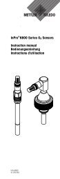
<strong>InPro</strong> <strong>7000</strong>-<strong>VP</strong> <strong>Series</strong><br />
2-electrode conductivity sensors<br />
2-Pol-Leitfähigkeits-Messzellen<br />
Sondes de conductivité à 2 électrodes<br />
<strong>Instruction</strong> <strong>manual</strong><br />
<strong>Bedienungsanleitung</strong><br />
Manuel d’utilisation<br />
<strong>InPro</strong> <strong>7000</strong>-<strong>VP</strong> <strong>Series</strong><br />
52 002 091
English Page 3<br />
Deutsch Seite 21<br />
Français Page 39
<strong>InPro</strong> <strong>7000</strong>-<strong>VP</strong> <strong>Series</strong> 3<br />
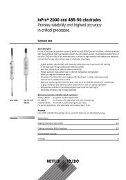
<strong>InPro</strong> <strong>7000</strong>-<strong>VP</strong> <strong>Series</strong><br />
2-electrode conductivity sensors<br />
<strong>Instruction</strong> <strong>manual</strong><br />
Subject to technical changes without prior notice.<br />
© It is strictly forbidden to reprint this instruction <strong>manual</strong> or any parts thereof without<br />
the written permission of Mettler-Toledo GmbH, Process Analytics, Industrie Nord,<br />
8902 Urdorf, Switzerland. No section or excerpt whatsoever may be reproduced or with<br />
the assistance of electronic systems be edited, duplicated or distributed, in particular in<br />
the form of photocopies, photographs, magnetic media or other recording methods. All<br />
rights reserved, especially the right of duplication and translation as well as in regard<br />
to patent and registration rights.<br />
Mettler-Toledo GmbH, 8606 Greifensee, Switzerland<br />
© 01 / 06 Mettler-Toledo GmbH, CH - 8606 Greifensee <strong>InPro</strong> <strong>7000</strong>-<strong>VP</strong> <strong>Series</strong><br />
Printed in USA 52 002 091
4 <strong>InPro</strong> <strong>7000</strong>-<strong>VP</strong> <strong>Series</strong><br />
Contents<br />
1 Product description 5<br />
1.1 Introduction 5<br />
1.2 Equipment and scope of delivery 5<br />
1.3 Technical data 6<br />
2 Safety 7<br />
2.1 Application compatibility 7<br />
2.2 Proper utilization 8<br />
2.3 Safety measures 8<br />
2.4 Use in Ex-zones 9<br />
3 Initial start-up 13<br />
3.1 Installation 13<br />
3.2 Electrical connections 14<br />
4 Maintenance and troubleshooting 16<br />
4.1 Conditions of warranty 16<br />
4.2 Maintenance 16<br />
4.3 Troubleshooting 17<br />
5 Removal from operation, storage, disposal 17<br />
5.1 Removal from operation 17<br />
5.2 Storage 18<br />
5.3 Disposal 18<br />
6 Dimensional drawings 18<br />
7 Accessories 20<br />
<strong>InPro</strong> <strong>7000</strong>-<strong>VP</strong> <strong>Series</strong><br />
© 01 / 06 Mettler-Toledo GmbH, CH - 8606 Greifensee<br />
52 002 091 Printed in USA
<strong>InPro</strong> <strong>7000</strong>-<strong>VP</strong> <strong>Series</strong> 5<br />
1 Product description<br />
1.1 Introduction<br />
Conformity<br />
<strong>InPro</strong> <strong>7000</strong>-<strong>VP</strong> <strong>Series</strong> 2-electrode sensors are in conformance with the<br />
following regulations (exceptions are described in section 1.3):<br />
Low voltage – EU Guidelines 73/23/EU<br />
guidelines: – Swiss Guidelines SR 734.26 NEV<br />
– Safety Guidelines EN61010-1<br />
– IP protection rating EN60529 IP68 (<strong>VP</strong> connector)<br />
EMC Guidelines:– EU Guidelines 89/336/EU<br />
– Swiss Guidelines SR 734.5 VEMV<br />
– Emission EN55022<br />
– Immunity EN50082-2<br />
Explosion protection<br />
– 94/9/EG<br />
– SNCH 04 ATEX 3637 X<br />
– L-5201 Sandweiler, SNCH 0499<br />
Certificates<br />
CE, Quality, Material Certificate following EN 10204 (3.1B) for sensor with<br />
316L SS electrodes, ATEX EU Guideline 94 / 9 / EWG.<br />
Markings<br />
The markings labeled on each sensor state the following information:<br />
METTLER TOLEDO<br />
CH-8902 Urdorf<br />
<strong>InPro</strong>700x-<strong>VP</strong><br />
II 1/2 G EEx ia IIC T3/T4/T5/T6<br />
Cell M: XXXXXX Temp. M: XXXXXX see instruction <strong>manual</strong><br />
Serial No: XXXXXXXXX Order No: XXXXXXXX SNCH 04 ATEX 3637 X<br />
1.2 Equipment and scope of delivery<br />
Scope of delivery<br />
The <strong>InPro</strong> <strong>7000</strong>-<strong>VP</strong> <strong>Series</strong> sensors are delivered ready for use. Each sensor<br />
is accompanied by this instruction <strong>manual</strong>, an individual «Certificate<br />
of Quality» and a Material Certificate following EN 10204 (exceptions:<br />
<strong>InPro</strong> <strong>7000</strong>-<strong>VP</strong> and <strong>InPro</strong> 7005-<strong>VP</strong>). Other Certificates may be included as<br />
0499<br />
© 01 / 06 Mettler-Toledo GmbH, CH - 8606 Greifensee <strong>InPro</strong> <strong>7000</strong>-<strong>VP</strong> <strong>Series</strong><br />
Printed in USA 52 002 091
6<br />
<strong>InPro</strong> <strong>7000</strong>-<strong>VP</strong> <strong>Series</strong><br />
specified for the individual product. Please check that the details given in<br />
the Certificate of Quality match the sensor label. For each sensor, the relevant<br />
cell constant has been determined individually in an ultrapure water<br />
system at 25 °C (77 °F) during the manufacturing process, and the value<br />
documented in the accompanying «Certificate of Quality».It is not necessary<br />
to re-calibrate the sensor before initial operation.<br />
Packaging<br />
The packaging consists of cardboard and plastic material.<br />
Keep the packaging for later use during storage or transportation of the sensor.<br />
Should you wish to dispose of the packaging material, please<br />
observe your local regulations as well as those data and instructions given<br />
in Chapter 5.3 of this <strong>manual</strong>.<br />
Unpacking and inspection<br />
Please check the sensors immediately during unpacking in order to determine<br />
possible damage or missing items. Any irregularities should immediately<br />
be reported to your carrier and to your supplier.<br />
1.3 Technical data<br />
Technical data <strong>InPro</strong> <strong>7000</strong>-<strong>VP</strong> <strong>InPro</strong> 7001-<strong>VP</strong> <strong>InPro</strong> 7002-<strong>VP</strong> <strong>InPro</strong> 7005-<strong>VP</strong><br />
Wetted Titanium, PEEK, 316L SS 316L SS, Titanium, PEEK,<br />
materials PVDF, Viton (1.4435), (1.4435), Viton, PTFE -<br />
PEEK, Viton PEEK coated 316 SS<br />
Temperature –10...100 °C –10...100 °C –10...120 °C –10...100 °C<br />
range (14...212 °F) (14...212 °F) (14...248 °F) (14...212 °F)<br />
Process adaption/ 3<br />
/4" NPT PG 13.5 Tri-Clamp 3<br />
/4" NPT<br />
connection 1" NPT conduit (1.5" & 2")<br />
Tuchenhagen<br />
Varivent<br />
(DN 40-DN 125)<br />
Max. pressure 34 bar 17 bar 31 bar 17 bar<br />
at 25 °C (77 °F) (500 psi) (250 psi) (450 psi) (250 psi)<br />
Sterilizability Non-sterilizable max. 131 °C max. 150 °C Non-sterilizable<br />
(max. 268 °F) (max. 312 °F)<br />
Protection class<br />
(<strong>VP</strong> connector)<br />
IP68 IP68 IP68 IP68<br />
(sensor: IP65)<br />
<strong>InPro</strong> <strong>7000</strong>-<strong>VP</strong> <strong>Series</strong><br />
© 01 / 06 Mettler-Toledo GmbH, CH - 8606 Greifensee<br />
52 002 091<br />
Printed in USA
<strong>InPro</strong> <strong>7000</strong>-<strong>VP</strong> <strong>Series</strong> 7<br />
Each <strong>InPro</strong> <strong>7000</strong>-<strong>VP</strong> <strong>Series</strong> sensor is equipped with an integral temperature<br />
probe Pt1000, IEC 751 Class A.<br />
The nominal cell constant is 0.1 cm -1 . The exact value is printed on the<br />
sensor label.<br />
For each sensor, the cell constant and temperature constant have been measured/established<br />
individually and the values documented in the accompanying<br />
Quality Certificate. All calibrations can be traced back to NIST and/or<br />
ASTM Standards.<br />
Both the measuring range and the system measurement accuracy strongly<br />
depend upon which type of transmitter is employed.<br />
Subject to technical changes<br />
Sensor<br />
Transmitter 7220 X M 700 Cond 7100 e Cond 7050 e<br />
<strong>InPro</strong> <strong>7000</strong>/7005 7 9 9 4<br />
<strong>InPro</strong> 7001 4 5 5 2<br />
<strong>InPro</strong> 7002 5 7 7 3<br />
1 0.01–120 µS/cm 4 0.02– 200 µS/cm 7 0.02–1.2000µ S/cm<br />
2 0.02– 50 µS/cm 5 0.02– 500 µS/cm 8 0.02–1.2500µ S/cm<br />
3 0.02–100 µS/cm 6 0.02–1000µ S/cm 9 0.02–10.000µ S/cm<br />
2 Safety<br />
2.1 Application compatibility<br />
The wetted material parts of the sensor (several different materials come<br />
into contact with the sample medium) can under some circumstance be<br />
incompatible with the particular composition of the process medium and/or<br />
of the operating conditions. Responsibility to verify application compatibility<br />
lies wholly with the user.<br />
The compatibility of different types of material are outlined on<br />
http://www.coleparmer.com/techinfo/chemcomp.asp.<br />
Mettler-Toledo GmbH, Process Analytics accepts no responsibility whatsoever<br />
for the correctness or accuracy of such details.<br />
© 01 / 06 Mettler-Toledo GmbH, CH - 8606 Greifensee <strong>InPro</strong> <strong>7000</strong>-<strong>VP</strong> <strong>Series</strong><br />
Printed in USA 52 002 091
8 <strong>InPro</strong> <strong>7000</strong>-<strong>VP</strong> <strong>Series</strong><br />
2.2 Proper utilization<br />
METTLER TOLEDO <strong>InPro</strong> <strong>7000</strong>-<strong>VP</strong> <strong>Series</strong> sensors are intended solely for the<br />
precise measurement of conductivity in aqueous and some limited nonaqueous<br />
solutions in industrial applications.<br />
Any other use, or any operation over and above that intended by the<br />
manufacturer, are not recommended and can lead to harm or injury to<br />
material/equipment and persons. This is also relevant for applications which<br />
do not comply with the technical data labeled on the sensor. For any<br />
damage arising from such misuse, the user assumes full and sole<br />
responsibility.<br />
2.3 Safety measures<br />
The <strong>InPro</strong> <strong>7000</strong>-<strong>VP</strong> <strong>Series</strong> sensors have been manufactured in line with<br />
state-of-the-art technology and in accordance with accepted technical<br />
safety regulations. Nevertheless, the sensors can still represent a source of<br />
risk and danger:<br />
– if the sensors are operated by insufficiently trained personnel,<br />
– if the sensors are employed incorrectly or not as intended by the<br />
manufacturer,<br />
– if the sensors are not regularly maintained or serviced.<br />
Local legislation and regulations must be observed at all times. Such<br />
stipulations do not form an integral part of this instruction <strong>manual</strong>.<br />
It is necessary to use protective gear, including gloves, for persons coming<br />
in contact with the fluid. It is recommended to use gloves when handling<br />
the electrodes of the sensor to limit contamination of the sensor.<br />
The user is responsible for the instruction and training of personnel. Additional<br />
copies of the instruction <strong>manual</strong> can be ordered from your supplier.<br />
This instruction <strong>manual</strong> is an essential element of the sensor equipment<br />
and must at all times be readily available to operators directly at the measurement<br />
site.<br />
Before the sensor is removed from the process/process adapter, it must be<br />
ensured that the process pressure has been reduced to a safe level and the<br />
process temperature lowered to a safe range. Any escape of hot process<br />
<strong>InPro</strong> <strong>7000</strong>-<strong>VP</strong> <strong>Series</strong><br />
© 01 / 06 Mettler-Toledo GmbH, CH - 8606 Greifensee<br />
52 002 091 Printed in USA
<strong>InPro</strong> <strong>7000</strong>-<strong>VP</strong> <strong>Series</strong><br />
9<br />
fluid under pressure can cause damage to material/equipment or injury to<br />
persons.<br />
No modification whatsoever may be carried out on the sensors. Any<br />
unauthorized modification or manipulation of the sensors results in immediate<br />
expiration of the full scope of warranty granted by the manufacturer.<br />
2.4 Use in Ex-zones<br />
Note!<br />
For intended installation in an Ex-classified area, please observe the following<br />
guidelines:<br />
Ex-classification:<br />
II 1/2 G EEx ia IIB T3/T4/T5/T6<br />
resp.<br />
II 1/2 G EEx ia IIC T3/T4/T5/T6<br />
steel or stainless steel coated with PTFE)<br />
(for sensors with polymer body)<br />
(for sensors made of stainless<br />
Marking and number of the test certificate:<br />
SNCH 04 ATEX 3637 X<br />
Ex-classification II 1/2 G EEx ia IIB T3 / T4 / T5 / T6<br />
resp. II 1/2 G EEx ia IIC T3 / T4 / T5 / T6 in accordance with EC Type<br />
Examination Certification SNCH 04 A TEX 3637 X<br />
Introduction<br />
The conductivity sensors with polymer body are in accordance with<br />
RL 94/9/EC (ATEX 95) Appendix 1 classified as plant equipment in the<br />
Equipment Group II Category 1/2G which in accordance with RL 99/92/EC<br />
(ATEX 137) may be employed in the Zones 0/1 or 0/2 or 1/2 as well as in<br />
Gas Groups IIA and IIB, areas in which there is potential risk of explosion<br />
of inflammable materials in the Temperature Classes T1 to T6.<br />
The conductivity sensors made of stainless steel or of stainless steel<br />
coated with PTFE coating are in accordance with RL 94/9/EC (ATEX 95)<br />
Appendix 1 classified as plant equipment in the Equipment Group II Category<br />
1/2G which in accordance with RL 99/92/EC (ATEX 137) may be<br />
© 01/06 Mettler-Toledo GmbH, CH - 8606 Greifensee <strong>InPro</strong> <strong>7000</strong>-<strong>VP</strong> <strong>Series</strong><br />
Printed in USA<br />
52 002 091
10 <strong>InPro</strong> <strong>7000</strong>-<strong>VP</strong> <strong>Series</strong><br />
employed in the Zones 0/1 or 0/2 or 1/2 as well as in Gas Groups IIA, IIB<br />
and IIC, areas in which there is potential risk of explosion of inflammable<br />
materials in the Temperature Classes T1 to T6.<br />
During installation and use of the equipment, the requirements of EN 60079-<br />
14 are to be fully complied with.<br />
Rated data<br />
Conductivity measuring circuit In fail-safe ignition protection class EEx ia IIC<br />
only for connection to a certified<br />
fail-safe circuit.<br />
Maximum values:<br />
U i ≤ 10 V<br />
I i ≤ 190 mA<br />
P i ≤ 175 mW<br />
The effective internal inductances and capacitances<br />
are negligibly small.<br />
Temperature measuring circuit In fail-safe ignition protection class EEx ia IIC<br />
only for connection to a certified<br />
fail-safe circuit.<br />
Maximum values:<br />
U i ≤ 10 V<br />
I i ≤ 10 mA<br />
P i ≤ 12 mW<br />
The effective internal inductances and<br />
capacitances are negligibly small.<br />
<strong>InPro</strong> <strong>7000</strong>-<strong>VP</strong> <strong>Series</strong><br />
© 01 / 06 Mettler-Toledo GmbH, CH - 8606 Greifensee<br />
52 002 091 Printed in USA
<strong>InPro</strong> <strong>7000</strong>-<strong>VP</strong> <strong>Series</strong> 11<br />
Special conditions X<br />
1. The maximum permissible (process) medium resp. ambient temperatures<br />
relative to the temperature class should be obtained from the<br />
following table:<br />
Temperature Class<br />
T6<br />
T5<br />
T4<br />
T3<br />
Max. medium resp. ambient<br />
temperature in Zone 0<br />
68 °C<br />
80 °C<br />
108 °C<br />
160 °C<br />
Max. medium resp. ambient<br />
temperature in Zone 1 and 2<br />
80 °C<br />
95 °C<br />
130 °C<br />
195 °C<br />
2. The measuring systems drawings must be followed for installation.<br />
3. The capacitance and inductance of the connecting cable must be taken<br />
into account for the layout.<br />
4. The metal body of the conductivity sensor or the safety weld-in sockets or<br />
the METTLER TOLEDO housing type InFit 76*-*** resp. InTrac 7**-***<br />
must be electrically connected to the main potential equalization system<br />
of the plant (grounded).<br />
5. The metal body of the conductivity sensor or the safety weld-in sockets or<br />
the METTLER TOLEDO housing type InFit 76*-*** resp. InTrac 7**-***<br />
are, if necessary, to be included into the recurring pressure test of the<br />
unit.<br />
© 01 / 06 Mettler-Toledo GmbH, CH - 8606 Greifensee <strong>InPro</strong> <strong>7000</strong>-<strong>VP</strong> <strong>Series</strong><br />
Printed in USA 52 002 091
12 <strong>InPro</strong> <strong>7000</strong>-<strong>VP</strong> <strong>Series</strong><br />
Declaration of conformity<br />
<strong>InPro</strong> <strong>7000</strong>-<strong>VP</strong> <strong>Series</strong><br />
© 01 / 06 Mettler-Toledo GmbH, CH - 8606 Greifensee<br />
52 002 091 Printed in USA
<strong>InPro</strong> <strong>7000</strong>-<strong>VP</strong> <strong>Series</strong> 13<br />
3 Initial start-up<br />
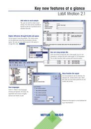
3.1 Installation<br />
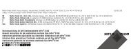
The sensors are to be mounted in such a way that the sample medium<br />
flows directly into the sensor through the orifice at the tip and re-emerges<br />
through the vent holes. Any other installation position of the sensors can<br />
create the risk of formation of airlocks, or of contamination through deposits<br />
of solid matter.<br />
Air bubbles can be trapped<br />
in the sensor cavity<br />
30º 30º<br />
Solids can be trapped<br />
in the sensor cavity<br />
Sensor orientation<br />
Flow<br />
direction<br />
Flow direction<br />
Vent hole<br />
T-piece<br />
Orientation in fluids<br />
with low velocity<br />
Sensor<br />
Flow of sample medium must be toward the face of the sensor. Air bubbles<br />
and solid matter deposits are to be avoided. A minimum clearance of 0.6<br />
cm ( 1 /4") between sensor and pipe wall must be maintained at the tip of<br />
the sensor.<br />
Vertical mounting (top entry) in a pipe is recommended only if the pipe is<br />
full and no air bubbles are able to develop in the flow.<br />
In the event of side mounting (side entry) of the sensor, vertical upward<br />
flow of sample process medium must be ensured.<br />
© 01 / 06 Mettler-Toledo GmbH, CH - 8606 Greifensee <strong>InPro</strong> <strong>7000</strong>-<strong>VP</strong> <strong>Series</strong><br />
Printed in USA 52 002 091
14 <strong>InPro</strong> <strong>7000</strong>-<strong>VP</strong> <strong>Series</strong><br />
3.2 Electrical connections<br />
All of the <strong>InPro</strong> <strong>7000</strong>-<strong>VP</strong> <strong>Series</strong> sensors can be connected to the associated<br />
transmitter using the appropriate multiwire cable from METTLER TOLEDO.<br />
Depending on which type of transmitter is employed, not all cable strands<br />
may have to be used.<br />
Colors and function of the cable strands (supplied separately)<br />
2-electrode sensor 4-electrode sensor Color<br />
Inner electrode Current electrode 1 white/blue<br />
Voltage electrode 1 white<br />
Voltage electrode 2 blue<br />
Outer electrode Current electrode 2 black<br />
Temperature probe T1 Temperature probe T1 green<br />
Temperature probe T2 Temperature probe T2 red<br />
Shielding Shielding transparent<br />
Connection to the relative transmitter must be followed according to the<br />
wiring diagram below.<br />
METTLER TOLEDO supplies the following cables<br />
Cable length<br />
Order No.<br />
11.5 m (5 ft) 58 080 201<br />
13.0 m (10 ft) 58 080 202<br />
14.6 m (15 ft) 58 080 203<br />
17.6 m (25 ft) 58 080 204<br />
15.2 m (50 ft) 58 080 205<br />
22.9 m (75 ft) 58 080 206<br />
30.5 m (100 ft) 58 080 207<br />
<strong>InPro</strong> <strong>7000</strong>-<strong>VP</strong> <strong>Series</strong><br />
© 01 / 06 Mettler-Toledo GmbH, CH - 8606 Greifensee<br />
52 002 091 Printed in USA
<strong>InPro</strong> <strong>7000</strong>-<strong>VP</strong> <strong>Series</strong> 15<br />
Wiring diagram<br />
Transmitter Cond 7050 e Cond 7050 e Cond 7100 e Cond 7100 e/2(X)H Cond 7100 PA<br />
model panel mount wall mount (4-wire unit) (2-wire unit) Cond 7100 e FF<br />
wire color<br />
white/blue 15 30 1 1 1<br />
transparent not used not used C 5 5<br />
white 16 31 2 2 2<br />
green 25 27 E 8 8<br />
red 24 26 D 7 7<br />
black 18 33 4 4 4<br />
blue 17 32 3 3 3<br />
shield 22 21 5 5 5<br />
Instrument Jumper Jumper<br />
Terminal 25–26 27–28<br />
jumper<br />
Transmitter model 7220 X (2-wire unit) M 700 (X) (4-wire unit)<br />
wire color<br />
white/blue 1 1<br />
transparent 5 16<br />
white 2 2<br />
green 8 18<br />
red 6 17<br />
black 4 4<br />
blue 3 3<br />
shield 5 5<br />
Instrument Jumper 7–8 Jumper 18–19<br />
Terminal<br />
jumper<br />
2-wire = two-wire, loop-powered transmitter<br />
4-wire = four-wire, mains-powered transmitter<br />
© 01 / 06 Mettler-Toledo GmbH, CH - 8606 Greifensee <strong>InPro</strong> <strong>7000</strong>-<strong>VP</strong> <strong>Series</strong><br />
Printed in USA 52 002 091
16 <strong>InPro</strong> <strong>7000</strong>-<strong>VP</strong> <strong>Series</strong><br />
4 Maintenance and troubleshooting<br />
4.1 Conditions of warranty<br />
METTLER TOLEDO guarantees the quality of materials and workmanship<br />
within a narrow range of manufacturing tolerances, so that the product<br />
purchased is free from any substantial deviations from material and<br />
manufacturing quality standards. The warranty is valid for a period of one<br />
year from date of delivery: If within this warranty period, any repair or<br />
replacement should become necessary, and such cause is not due to<br />
misuse or incorrect application, please return the sensor, freight pre-paid,<br />
to your appropriate METTLER TOLEDO supplier. Repair work will be carried<br />
out free of charge. Final decision on whether the defect is due to a manufacturing<br />
error or to incorrect operation of the sensor by the customer<br />
is made at the option of the Customer Service department of METTLER<br />
TOLEDO. After expiration of the warranty period, sensors will be repaired or<br />
replaced on an exchange basis against payment of the costs involved.<br />
4.2 Maintenance<br />
Dirty or contaminated sensors can deliver incorrect measurement values.<br />
If fouling is presumed, the sensor is to be removed from operation and the<br />
electrodes as well as the insulation between the electrodes cleaned with<br />
a soft cloth. Suitable cleaning solutions are mild detergents or diluted<br />
acids (< 0.5 % by wt.) such as hydrochloric or nitric acid. Never use cleaning<br />
agents that are not compatible with the material to be cleaned.<br />
When handling acids, precautionary measures are to be taken.<br />
The sensor must be thoroughly flushed with distilled or deionized water<br />
prior to re-installation.<br />
Following cleaning and re-installation into the process, it can take from<br />
several minutes up to several hours until the sensor delivers the originally<br />
measured value.<br />
<strong>InPro</strong> <strong>7000</strong>-<strong>VP</strong> <strong>Series</strong><br />
© 01 / 06 Mettler-Toledo GmbH, CH - 8606 Greifensee<br />
52 002 091 Printed in USA
<strong>InPro</strong> <strong>7000</strong>-<strong>VP</strong> <strong>Series</strong> 17<br />
4.3 Troubleshooting<br />
Error Possible cause Corrective action<br />
No signal on display Electrical connections Check all connections<br />
either missing or<br />
and associated cabling<br />
incorrectly in place.<br />
Sensor is not in contact<br />
Check installation<br />
with the sample medium<br />
for air pockets<br />
No temperature signal Temperature probe is Check all connections<br />
not connected<br />
and associated cabling<br />
Transmitter does not support Replacement of transmitter<br />
Pt1000 RTD<br />
or sensor necessary<br />
Incorrect or unstable Sensor is contaminated/ Clean the sensor<br />
measurement reading fouled (electrodes)<br />
Sensor is installed too<br />
Ensure minimum distance<br />
close to pipe wall<br />
of 0.6 cm ( 1 /4") between<br />
sensor tip and pipe wall<br />
is maintained<br />
5 Removal from operation, storage, disposal<br />
5.1 Removal from operation<br />
The sensor is only conditionally subject to aging. When used as intended<br />
and appropriately maintained and serviced, the lifetime of the sensor can<br />
extend to several years.<br />
Before removing the sensor from the process/process adapter, it must be<br />
ensured that the process pressure has been reduced to a safe level and<br />
the process temperature has lowered to a safe range. Any escape of hot<br />
process medium under pressure can cause damage to material/equipment<br />
or injury to persons.<br />
After removal from the process the sensor should first be flushed with<br />
distilled water.<br />
If the sensor incurs a defect, it can not be repaired and must be disposed<br />
under observance of prevailing local regulations.<br />
© 01 / 06 Mettler-Toledo GmbH, CH - 8606 Greifensee <strong>InPro</strong> <strong>7000</strong>-<strong>VP</strong> <strong>Series</strong><br />
Printed in USA 52 002 091
18 <strong>InPro</strong> <strong>7000</strong>-<strong>VP</strong> <strong>Series</strong><br />
5.2 Storage<br />
5.3 Disposal<br />
If the sensor is not use, it can be stored dry. However, it has to be reconditioned<br />
in the process fluid accordingly prior to renewed operation. This<br />
procedure may take several hours to complete.<br />
Disposal is to be carried out by the user in accordance with valid local<br />
regulations.<br />
The packaging consists of:<br />
– cardboard<br />
– plastic film<br />
The sensor is of:<br />
– medium-wetted materials according to the specifications of the sensor<br />
– electronics material (cable, components)<br />
– PEEK (plug)<br />
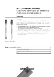
6 Dimensional drawings<br />
<strong>InPro</strong> <strong>7000</strong>-<strong>VP</strong><br />
<strong>InPro</strong> 7005-<strong>VP</strong><br />
635<br />
25.0<br />
457<br />
18.0<br />
153.2<br />
6.03<br />
82.3<br />
3.24<br />
29.2<br />
1.15<br />
34.0<br />
1.35<br />
75<br />
2.97<br />
cm<br />
inch<br />
12.7<br />
.500<br />
12.7<br />
.500<br />
<strong>InPro</strong> <strong>7000</strong>-<strong>VP</strong> <strong>Series</strong><br />
© 01 / 06 Mettler-Toledo GmbH, CH - 8606 Greifensee<br />
52 002 091 Printed in USA
<strong>InPro</strong> <strong>7000</strong>-<strong>VP</strong> <strong>Series</strong> 19<br />
<strong>InPro</strong> 7001-<strong>VP</strong> 3.1B<br />
74.09<br />
2.917<br />
a = Length<br />
<strong>InPro</strong> 7001/120-<strong>VP</strong> 120 (4.73)<br />
<strong>InPro</strong> 7001/225-<strong>VP</strong> 225 (8.86)<br />
10.41<br />
.410<br />
<strong>InPro</strong> 7002-TC-<strong>VP</strong> 3.1B <strong>InPro</strong> 7002-VAR-<strong>VP</strong> 3.1B<br />
2.55<br />
64.85<br />
3.31<br />
83.99<br />
52002857<br />
64.5<br />
2.54<br />
4.43<br />
112.59<br />
6.35<br />
.250<br />
R.25 [R6.35]<br />
1.40<br />
35.44<br />
.62<br />
15.75<br />
15.9<br />
.625<br />
a = Length<br />
<strong>InPro</strong> 7002/1.5" TC-<strong>VP</strong> 85.1 (3.35)<br />
<strong>InPro</strong> 7002/2" TC-<strong>VP</strong> 104.1 (4.10)<br />
<strong>InPro</strong> 7002-VAR-<strong>VP</strong> 35.44 (1.40)<br />
© 01 / 06 Mettler-Toledo GmbH, CH - 8606 Greifensee <strong>InPro</strong> <strong>7000</strong>-<strong>VP</strong> <strong>Series</strong><br />
Printed in USA 52 002 091
20 <strong>InPro</strong> <strong>7000</strong>-<strong>VP</strong> <strong>Series</strong><br />
7 Accessories<br />
O-rings<br />
Sensor Standard O-ring Complementary O-rings Order No.<br />
<strong>InPro</strong> 7001/120-<strong>VP</strong> 3.1B Viton FDA 20 302 1000<br />
<strong>InPro</strong> 7001/225-<strong>VP</strong> 3.1B (10.77 x 2.62)<br />
Silicon FDA (10.77 x 2.62) 20 301 1136<br />
Kalrez (10.78 x 2.62) 20 304 1000<br />
Kalrez FDA (10.78 x 2.62) 20 304 1034<br />
EPDM FDA (10.77 x 2.62) 20 303 1206<br />
Cable<br />
Cable length<br />
Order No.<br />
11.5 m (5 ft) 58 080 201<br />
13.0 m (10 ft) 58 080 202<br />
14.6 m (15 ft) 58 080 203<br />
17.6 m (25 ft) 58 080 204<br />
15.2 m (50 ft) 58 080 205<br />
22.9 m (75 ft) 58 080 206<br />
30.5 m (100 ft) 58 080 207<br />
The max. cable length recommended is 60 m.<br />
Cable adapter from <strong>VP</strong> (male) to Conxal (female)<br />
Designation Cable length Order No.<br />
<strong>VP</strong> cable adapter 0.9 m (3 ft) 58 080 101<br />
Housings for <strong>InPro</strong> <strong>7000</strong>-<strong>VP</strong> <strong>Series</strong><br />
Designation Applied as Suitable sensor<br />
InFit 761 e Stationary housing <strong>InPro</strong> 7001/120 and 225-<strong>VP</strong><br />
InFit 762 e Stationary housing <strong>InPro</strong> 7001/120-<strong>VP</strong><br />
InFit 777 e Rectractable housing <strong>InPro</strong> 7001/225-<strong>VP</strong><br />
InFit 787 e Rectractable housing <strong>InPro</strong> 7001/120-<strong>VP</strong><br />
InFit 798 e Rectractable housing <strong>InPro</strong> 7001/120-<strong>VP</strong><br />
InDip 550 Immersion housing <strong>InPro</strong> <strong>7000</strong>-<strong>VP</strong>/<strong>InPro</strong> 7005-<strong>VP</strong><br />
<strong>InPro</strong> <strong>7000</strong>-<strong>VP</strong> <strong>Series</strong><br />
© 01 / 06 Mettler-Toledo GmbH, CH - 8606 Greifensee<br />
52 002 091 Printed in USA
<strong>InPro</strong> <strong>7000</strong>-<strong>VP</strong> <strong>Series</strong> 21<br />
<strong>InPro</strong> <strong>7000</strong>-<strong>VP</strong> Serie<br />
2-Pol-Leitfähigkeits-Messzellen<br />
<strong>Bedienungsanleitung</strong><br />
Technische Änderungen ohne vorherige Anzeige sind vorbehalten.<br />
© Der Nachdruck dieser <strong>Bedienungsanleitung</strong>, auch auszugsweise, ist verboten.<br />
Ohne schriftliche Bewilligung der Firma Mettler-Toledo GmbH, Process Analytics, Industrie<br />
Nord, CH - 8902 Urdorf, dürfen keine Teile davon in irgendeiner Form reproduziert<br />
oder unter Anwendung elektronischer Systeme, insbesondere in Form von Fotokopien,<br />
Magnetverfahren oder anderen Aufzeichnungsarten, verarbeitet, vervielfältigt oder<br />
verbreitet werden. Alle Rechte, insbesondere das Recht der Vervielfältigung und Übersetzung<br />
sowie Patent- oder Registrierungsrechte, sind vorbehalten.<br />
Mettler-Toledo GmbH, CH - 8606 Greifensee<br />
© 01 / 06 Mettler-Toledo GmbH, CH - 8606 Greifensee <strong>InPro</strong> <strong>7000</strong>-<strong>VP</strong> <strong>Series</strong><br />
Printed in USA 52 002 091
22 <strong>InPro</strong> <strong>7000</strong>-<strong>VP</strong> <strong>Series</strong><br />
Inhaltsverzeichnis<br />
1 Produktebeschreibung 23<br />
1.1 Einleitung 23<br />
1.2 Ausstattung und Lieferumfang 23<br />
1.3 Technische Daten 24<br />
2 Sicherheit 25<br />
2.1 Anwendungskompatibilität 25<br />
2.2 Bestimmungsgemässe Verwendung 26<br />
2.3 Sicherheitsmassnahmen 26<br />
2.4 Einsatz im Ex-Bereich 27<br />
3 Inbetriebnahme 31<br />
3.1 Montage 31<br />
3.2 Elektrische Anschlüsse 32<br />
4 Wartung und Störungsbehebung 34<br />
4.1 Garantiebestimmungen 34<br />
4.2 Wartung 34<br />
4.3 Störungsbehebung 35<br />
5 Ausserbetriebsetzung, Lagerung, Entsorgung 35<br />
5.1 Ausserbetriebsetzung 35<br />
5.2 Lagerung 35<br />
5.3 Entsorgung 36<br />
6 Masszeichnungen 36<br />
7 Zubehör 38<br />
<strong>InPro</strong> <strong>7000</strong>-<strong>VP</strong> <strong>Series</strong><br />
© 01 / 06 Mettler-Toledo GmbH, CH - 8606 Greifensee<br />
52 002 091 Printed in USA
<strong>InPro</strong> <strong>7000</strong>-<strong>VP</strong> <strong>Series</strong> 23<br />
1 Produktebeschreibung<br />
1.1 Einleitung<br />
Konformität<br />
2-Pol-Messzellen der <strong>InPro</strong> <strong>7000</strong>-<strong>VP</strong> Serie entsprechen folgenden Bestimmungen<br />
(Ausnahme siehe 1.3):<br />
Niederspannungs- – EU Richtlinie 73/23/EU<br />
richtlinien: – Schweizer Richtlinie SR 734.26 NEV<br />
– Sicherheitsrichtlinien EN61010-1<br />
– IP-Schutzgrad EN60529 IP68 (<strong>VP</strong>-Stecker)<br />
EMV Richtlinien: – EU Richtlinie 89/336/EU<br />
– Schweizer Richtlinie SR 734.5 VEMV<br />
– Emission EN55022<br />
– Immunität EN50082-2<br />
Explosionsschutzrichtlinie<br />
– 94/9/EG<br />
– SNCH 04 ATEX 3637 X<br />
– L-5201 Sandweiler, SNCH 0499<br />
Zertifikate<br />
CE, Qualität, Materialzertifikat nach EN 10204 (3.1B) für Messzellen mit<br />
Elektroden aus rostfreiem Stahl, ATEX EU Guideline 94 / 9 / EWG.<br />
Kennzeichnung<br />
Der Aufdruck auf jeder Messzelle enthält folgende Informationen:<br />
METTLER TOLEDO<br />
CH-8902 Urdorf<br />
<strong>InPro</strong>700x-<strong>VP</strong><br />
II 1/2 G EEx ia IIC T3/T4/T5/T6<br />
Cell M: XXXXXX Temp. M: XXXXXX see instruction <strong>manual</strong><br />
Serial No: XXXXXXXXX Order No: XXXXXXXX SNCH 04 ATEX 3637 X<br />
0499<br />
1.2 Ausstattung und Lieferumfang<br />
Lieferumfang<br />
Die Messzellen der <strong>InPro</strong> <strong>7000</strong>-<strong>VP</strong> Serie werden gebrauchsfertig geliefert.<br />
Jeder Messzelle ist diese <strong>Bedienungsanleitung</strong>, ein individuelles «Certificate<br />
of Quality» sowie ein Materialzertifikat nach EN 10204 beigelegt (Aus-<br />
© 01 / 06 Mettler-Toledo GmbH, CH - 8606 Greifensee <strong>InPro</strong> <strong>7000</strong>-<strong>VP</strong> <strong>Series</strong><br />
Printed in USA 52 002 091
24<br />
<strong>InPro</strong> <strong>7000</strong>-<strong>VP</strong> <strong>Series</strong><br />
nahme: <strong>InPro</strong> <strong>7000</strong>-<strong>VP</strong> und <strong>InPro</strong> 7005-<strong>VP</strong>). Weitere Zertifikate können der<br />
Packung beiliegen. Überprüfen sie die Angaben des Zertifikates mit dem Aufdruck<br />
auf der Messzelle. Bei jeder Messzelle wird die Zellkonstante bei der<br />
Herstellung in einem Reinstwasserkreislauf bei 25 °C individuell bestimmt<br />
und im beigelegten «Certificate of Quality» dokumentiert. Eine erneute<br />
Kalibrierung der Messzelle vor der Inbetriebnahme wird nicht empfohlen.<br />
Verpackung<br />
Die Verpackung besteht aus Karton und Plastik<br />
Bewahren Sie die Verpackung, für eine spätere Lagerung oder einen Transport<br />
der Messzelle, auf. Falls Sie die Verpackung entsorgen wollen, beachten<br />
Sie die lokalen Vorschriften sowie Abschnitt 5.3.<br />
Kontrolle der Lieferung<br />
Bitte prüfen Sie die Messzelle beim Auspacken auf eventuelle Beschädigungen.<br />
Falls Sie solche feststellen, melden Sie dies umgehend dem Transporteur<br />
und ihrem Lieferanten.<br />
1.3 Technische Daten<br />
Technische Daten <strong>InPro</strong> <strong>7000</strong>-<strong>VP</strong> <strong>InPro</strong> 7001-<strong>VP</strong> <strong>InPro</strong> 7002-<strong>VP</strong> <strong>InPro</strong> 7005-<strong>VP</strong><br />
Benetzte Titan, PEEK, 316L rostfreier 316L rostfreier Titan, PEEK,<br />
Werk- PVDF, Viton Stahl (1.4435), Stahl (1.4435), PTFE beschichter<br />
stoffe PEEK, Viton PEEK Stahl 316, Viton<br />
Temperaturbereich –10...100 °C –10...100 °C –10...120 °C –10...100 °C<br />
Prozess- 3<br />
/4" NPT PG 13.5 Tri-Clamp 3<br />
/4" NPT<br />
anschluss 1" NPT conduit (1.5" & 2")<br />
Tuchenhagen<br />
Varivent<br />
(DN 40-DN 125)<br />
Max. Druck 34 bar 17 bar 31 bar 17 bar<br />
bei 25 °C<br />
Sterilisierbarkeit Nicht max. 131 °C max. 150 °C Nicht<br />
sterilisierbar<br />
sterilisierbar<br />
Schutzart<br />
(<strong>VP</strong>-Stecker)<br />
IP68 IP68 IP68 IP68<br />
(Sensor: IP65)<br />
<strong>InPro</strong> <strong>7000</strong>-<strong>VP</strong> <strong>Series</strong><br />
© 01 / 06 Mettler-Toledo GmbH, CH - 8606 Greifensee<br />
52 002 091<br />
Printed in USA
<strong>InPro</strong> <strong>7000</strong>-<strong>VP</strong> <strong>Series</strong> 25<br />
Alle Messzellen der <strong>InPro</strong> <strong>7000</strong>-<strong>VP</strong> Serie haben einen eingebauten Temperaturfühler<br />
Pt1000, IEC 751 Klasse A.<br />
Die nominelle Zellkonstante ist 0.1 cm -1 . Der exakte Wert ist auf dem Etikett<br />
aufgedruckt.<br />
Bei jeder Messzelle wird die Zellkonstante und die Temperaturkonstante<br />
individuell ausgemessen und im beigelegten Qualitätszertifikat dokumentiert.<br />
Alle Kalibrierungen lassen sich auf NIST- und/oder ASTM-Standards<br />
zurückführen.<br />
Messbereich und Systemmessgenauigkeit hängen stark vom eingesetzten<br />
Transmitter ab.<br />
Technische Änderungen vorbehalten<br />
Sensor<br />
Transmitter 7220 X M 700 Cond 7100 e Cond 7050 e<br />
<strong>InPro</strong> <strong>7000</strong>/7005 7 9 9 4<br />
<strong>InPro</strong> 7001 4 5 5 2<br />
<strong>InPro</strong> 7002 5 7 7 3<br />
1 0.01–120 µS/cm 4 0.02– 200 µS/cm 7 0.02–1.2000µ S/cm<br />
2 0.02– 50 µS/cm 5 0.02– 500 µS/cm 8 0.02–1.2500µ S/cm<br />
3 0.02–100 µS/cm 6 0.02–1000µ S/cm 9 0.02–10.000µ S/cm<br />
2 Sicherheit<br />
2.1 Anwendungskompatibilität<br />
Das benetzte Sensormaterial (mehrere Materialien im Kontakt mit dem<br />
Prozessmedium) ist u.U. nicht mit der Prozesszusammensetzung und den<br />
Betriebsbedingungen kompatibel. Die Anwendungskompatibilität liegt ganz<br />
in der Verantwortung des Bedieners.<br />
Unter http://www.coleparmer.com/techinfo/chemcomp.asp können verschiedene<br />
Materialkompatibiltäten nachgeschaut werden. Für die Richtigkeit<br />
der gemachten Angaben kann Mettler-Toledo GmbH, Process Analytics<br />
keine Verantwortung übernehmen.<br />
© 01 / 06 Mettler-Toledo GmbH, CH - 8606 Greifensee <strong>InPro</strong> <strong>7000</strong>-<strong>VP</strong> <strong>Series</strong><br />
Printed in USA 52 002 091
26 <strong>InPro</strong> <strong>7000</strong>-<strong>VP</strong> <strong>Series</strong><br />
2.2 Bestimmungsgemässe Verwendung<br />
Die METTLER TOLEDO <strong>InPro</strong> <strong>7000</strong>-<strong>VP</strong> Serie Messzellen sind für die präzise<br />
Leitfähigkeitsmessungen in wässrigen oder teilweise wässrigen Lösungen<br />
in industriellen Anwendungen bestimmt.<br />
Jede andere oder darüber hinausgehende Verwendung gilt als nicht bestimmungsgemäss<br />
missbräuchlich und kann zur Gefährdung von Personen<br />
oder zu Materialschäden führen. Dies gilt auch für Anwendungen, die<br />
nicht den technischen Daten entsprechen. Für allfällige Schäden, die auf<br />
einen solche Verwendung zurückzuführen sind, trägt der Anwender das<br />
alleinige Risiko.<br />
2.3 Sicherheitsmassnahmen<br />
Die Messzellen <strong>InPro</strong> <strong>7000</strong>-<strong>VP</strong> Serie sind nach dem Stand der Technik und<br />
den anerkannten sicherheitstechnischen Regeln gebaut. Dennoch können<br />
von den Messzellen Risiken und Gefahren ausgehen:<br />
– wenn die Messzellen von ungenügend ausgebildeten Personen bedient<br />
werden,<br />
– wenn die Messzellen nicht bestimmungsgemäss verwendet werden,<br />
– wenn die Messzellen nicht regelmässig gewartet werden.<br />
Die lokalen Gesetze und Vorschriften müssen immer beachtet werden. Sie<br />
sind nicht Bestandteil dieser <strong>Bedienungsanleitung</strong>.<br />
Das Tragen von persönlicher Schutzausrüstung wie Schutzbrille und Schutzkleidung<br />
ist grundsätzlich dann erforderlich, wenn das Risiko besteht, mit<br />
der Prozessflüssigkeit in Berührung zu geraten. Zur Verhinderung von Verschmutzungen<br />
der Elektrodenoberfläche wird empfohlen, Handschuhe zu<br />
tragen.<br />
Der Betreiber ist für die Instruktion des Personals verantwortlich. Dazu kann<br />
diese Betriebsanleitung auch nachbestellt werden. Diese Betriebsanleitung<br />
muss als Bestandteil der Messzellen jederzeit dem Bedienungspersonal am<br />
Einsatzort der Messzelle zur Verfügung stehen.<br />
Vor dem Entfernen der Messzelle muss sichergestellt sein, dass der Prozessdruck<br />
reduziert und die Prozesstemperatur auf einen sicheren Bereich<br />
abgesenkt ist. Heisse, unter Druck austretende Prozessflüssigkeit kann zu<br />
Schäden an Material und zur Gefährdung von Personen führen.<br />
<strong>InPro</strong> <strong>7000</strong>-<strong>VP</strong> <strong>Series</strong><br />
© 01 / 06 Mettler-Toledo GmbH, CH - 8606 Greifensee<br />
52 002 091 Printed in USA
<strong>InPro</strong> <strong>7000</strong>-<strong>VP</strong> <strong>Series</strong> 27<br />
An der Messzelle dürfen keine Modifikationen vorgenommen werden. Durch<br />
nichtautorisierte Modifikationen erlischt jegliche Gewährleistung.<br />
2.4 Einsatz im Ex-Bereich<br />
Hinweis!<br />
Für die Installation im Ex-Bereich beachten Sie bitte die nachfolgenden Richtlinien:<br />
Ex-Klassifikation:<br />
II 1/2 G EEx ia IIB T3 / T4 / T5 / T6 (Für Sensoren aus Kunststoff)<br />
bzw.<br />
II 1/2 G EEx ia IIC T3 / T4 / T5 / T6 (Für Sensoren aus Metall bzw.<br />
für Sensoren aus Metall mit Kunststoff beschichtet)<br />
Kennzeichnung und Nummer der Bescheinigung:<br />
SNCH 04 ATEX 3637 X<br />
Ex-Klassifikation II 1/2 G EEx ia IIB T3 / T4 / T5 / T6<br />
bzw. II 1/2 G EEx ia IIC T3 / T4 / T5 / T6 laut EG-Baumusterprüfbescheinigung<br />
SNCH 04 ATEX 3637 X<br />
Einleitung<br />
Die Leitfähigkeitssensoren aus Kunststoff sind nach RL 94/9/EG (ATEX 95)<br />
Anhang I Geräte der Gerätegruppe II Kategorie 1/2G die nach RL 99/92/EG<br />
(ATEX 137) in den Zonen 0/1 oder 0/2 oder 1/2 sowie den Gasgruppen<br />
IIA und IIB, die durch brennbare Stoffe im Bereich der Temperaturklassen<br />
T1 bis T6 explosionsgefährdet sind, eingesetzt werden dürfen.<br />
Die Leitfähigkeitssensoren aus Metall bzw. aus Metall mit Kunststoff<br />
beschichtet sind nach RL 94/9/EG (ATEX 95) Anhang I Geräte der Gerätegruppe<br />
II Kategorie 1/2G die nach RL 99/92/EG (ATEX 137) in den Zonen<br />
0/1 oder 0/2 oder 1/2 sowie den Gasgruppen IIA, IIB und IIC, die durch<br />
brennbare Stoffe im Bereich der Temperaturklassen T1 bis T6 explosionsgefährdet<br />
sind, eingesetzt werden dürfen.<br />
© 01 / 06 Mettler-Toledo GmbH, CH - 8606 Greifensee <strong>InPro</strong> <strong>7000</strong>-<strong>VP</strong> <strong>Series</strong><br />
Printed in USA 52 002 091
28 <strong>InPro</strong> <strong>7000</strong>-<strong>VP</strong> <strong>Series</strong><br />
Bei der Verwendung/Installation sind die Anforderungen nach EN 60079-<br />
14 einzuhalten.<br />
Nenndaten<br />
Leitfähigkeits-Messstromkreis In Zündschutzart Eigensicherheit EEx ia IIC<br />
nur zum Anschluss an einen zertifizierten<br />
eigensicheren Stromkreis mit<br />
linearer Kennlinie.<br />
Höchstwerte:<br />
U i ≤ 10 V<br />
I i ≤ 190 mA<br />
P i ≤ 175 mW<br />
Die wirksamen inneren Induktivitäten und<br />
Kapazitäten sind vernachlässigbar klein.<br />
Temperatur-Messstromkreis In Zündschutzart Eigensicherheit EEx ia IIC<br />
nur zum Anschluss an einen zertifizierten<br />
eigensicheren Stromkreis mit<br />
linearer Kennlinie.<br />
Höchstwerte:<br />
U i ≤ 10 V<br />
I i ≤ 10 mA<br />
P i ≤ 12 mW<br />
Die wirksamen inneren Induktivitäten und<br />
Kapazitäten sind vernachlässigbar klein.<br />
<strong>InPro</strong> <strong>7000</strong>-<strong>VP</strong> <strong>Series</strong><br />
© 01 / 06 Mettler-Toledo GmbH, CH - 8606 Greifensee<br />
52 002 091 Printed in USA
<strong>InPro</strong> <strong>7000</strong>-<strong>VP</strong> <strong>Series</strong> 29<br />
Besondere Bedingungen X<br />
1. Die maximal zulässigen Mediums- bzw. Umgebungstemperaturen sind<br />
entsprechend der Temperaturklasse der folgenden Tabelle zu entnehmen:<br />
Temperaturklasse<br />
T6<br />
T5<br />
T4<br />
T3<br />
Max. Mediums- bzw. Umgebungstemperatur<br />
in Zone 0<br />
68 °C<br />
80 °C<br />
108 °C<br />
160 °C<br />
Max. Mediums- bzw. Umgebungstemperatur<br />
in Zone 1 und 2<br />
80 °C<br />
95 °C<br />
130 °C<br />
195 °C<br />
2. Für die Installation sind die Systemzeichnungen / Anschlussbilder der<br />
Messsysteme zu beachten.<br />
3. Die Kapazität und Induktivität des Verbindungskabels ist bei der Auslegung<br />
zu berücksichtigen.<br />
4. Der Metallkörper des Leitfähigkeitssensors bzw. der Sicherheits-Einschweissstutzen<br />
bzw. die Armaturen METTLER TOLEDO InFit 76*-***<br />
oder InTrac 7**-*** müssen mit dem Potentialausgleichsystem der<br />
Anlage leitend verbunden sein.<br />
5. Der Metallkörper des Leitfähigkeitssensors bzw. der Sicherheits-Einschweissstutzen<br />
bzw. die Armaturen METTLER TOLEDO InFit 76*-***<br />
oder InTrac 7**-*** sind gegebenenfalls in die wiederkehrende Druckprüfung<br />
der Anlage einzubeziehen.<br />
© 01 / 06 Mettler-Toledo GmbH, CH - 8606 Greifensee <strong>InPro</strong> <strong>7000</strong>-<strong>VP</strong> <strong>Series</strong><br />
Printed in USA 52 002 091
30 <strong>InPro</strong> <strong>7000</strong>-<strong>VP</strong> <strong>Series</strong><br />
Konformitätserklärung<br />
<strong>InPro</strong> <strong>7000</strong>-<strong>VP</strong> <strong>Series</strong><br />
© 01 / 06 Mettler-Toledo GmbH, CH - 8606 Greifensee<br />
52 002 091 Printed in USA
<strong>InPro</strong> <strong>7000</strong>-<strong>VP</strong> <strong>Series</strong> 31<br />
3 Inbetriebnahme<br />
3.1 Montage<br />
Die Messzellen werden so installiert, dass das Medium direkt in die Messzellenöffnung<br />
strömt und durch die Entlüftungsöffnungen wieder austritt. Bei<br />
anderen Installationen besteht die Gefahr von Lufteinschlüssen oder der<br />
Ablagerung von festen Verunreinigungen.<br />
Luft wird im Sensor eingeschlossen<br />
30º 30º<br />
Schlamm wird im<br />
Sensor eingeschlossen<br />
Sensororientierung<br />
Flussrichtung<br />
Flussrichtung<br />
Entlüftungsöffnung<br />
T-Stück<br />
Orientierung in Proben<br />
mit niedriger Geschwindigkeit<br />
Sensor<br />
Die Messzelle sollte von vorne angeströmt werden. Luftblasen und Ablagerungen<br />
von festen Partikeln sollten vermieden werden. Ein Abstand von<br />
0.6 cm zwischen dem vorderen Ende der Messzelle und der Rohrleitung<br />
muss eingehalten werden.<br />
Vertikaler Einbau ist nur möglich, falls die Rohrleitung gefüllt ist und keine<br />
Luftblasen entstehen können.<br />
Bei seitlichem Einbau sollte die Flussrichtung aufwärts sein.<br />
© 01 / 06 Mettler-Toledo GmbH, CH - 8606 Greifensee <strong>InPro</strong> <strong>7000</strong>-<strong>VP</strong> <strong>Series</strong><br />
Printed in USA 52 002 091
32 <strong>InPro</strong> <strong>7000</strong>-<strong>VP</strong> <strong>Series</strong><br />
3.2 Elektrische Anschlüsse<br />
Alle Messzellen der <strong>InPro</strong> <strong>7000</strong>-<strong>VP</strong> Serie lassen sich über ein Mehrlitzenkabel<br />
von METTLER TOLEDO an die entsprechenden Transmitter<br />
anschliessen. Je nach Transmitter werden nicht alle Litzen benötigt.<br />
Farben und Funktionen des Kabels (separat geliefert)<br />
2-Pol-Messzelle 4-Pol-Messzelle Farbe<br />
Innere Elektrode Stromelektrode 1 Weiss/Blau<br />
Spannungselektrode 1 Weiss<br />
Spannungselektrode 2 Blau<br />
Äussere Elektrode Stromelektrode 2 Schwarz<br />
Temperaturfühler T1 Temperaturfühler T1 Grün<br />
Temperaturfühler T2 Temperaturfühler T2 Rot<br />
Abschirmung Abschirmung Transparent<br />
Der Anschluss an den entsprechenden Transmitter muss dem untenstehenden<br />
Anschlussschema entnommen werden.<br />
METTLER TOLEDO liefert folgende Kabel<br />
Kabellänge<br />
Artikel-Nr.<br />
11.5 m 58 080 201<br />
13.0 m 58 080 202<br />
14.6 m 58 080 203<br />
17.6 m 58 080 204<br />
15.2 m 58 080 205<br />
22.9 m 58 080 206<br />
30.5 m 58 080 207<br />
<strong>InPro</strong> <strong>7000</strong>-<strong>VP</strong> <strong>Series</strong><br />
© 01 / 06 Mettler-Toledo GmbH, CH - 8606 Greifensee<br />
52 002 091 Printed in USA
<strong>InPro</strong> <strong>7000</strong>-<strong>VP</strong> <strong>Series</strong> 33<br />
Anschlussschema<br />
Transmitter Cond 7050 e Cond 7050 e Cond 7100 e Cond 7100 e/2(X)H Cond 7100 PA<br />
Modell Schalttafel- Wand- (4-Leiter- (2-Leiter- Cond 7100 e FF<br />
montage montage Gerät) Gerät)<br />
Litzenfarbe<br />
Weiss/Blau 15 30 1 1 1<br />
Transparent unbeschaltet unbeschaltet C 5 5<br />
Weiss 16 31 2 2 2<br />
Grün 25 27 E 8 8<br />
Rot 24 26 D 7 7<br />
Schwarz 18 33 4 4 4<br />
Blau 17 32 3 3 3<br />
Schirm 22 21 5 5 5<br />
Verwendung Brücke Brücke<br />
von zwischen zwischen<br />
Brücken 25–26 27–28<br />
Transmitter Modell 7220 X (2-Leiter-Gerät) M700(X) (4-Leiter-Gerät)<br />
Litzenfarbe<br />
Weiss/Blau 1 1<br />
Transparent 5 16<br />
Weiss 2 2<br />
Grün 8 18<br />
Rot 6 17<br />
Schwarz 4 4<br />
Blau 3 3<br />
Schirm 5 5<br />
Verwendung von Brücke 7–8 Brücke 18–19<br />
Brücken<br />
© 01 / 06 Mettler-Toledo GmbH, CH - 8606 Greifensee <strong>InPro</strong> <strong>7000</strong>-<strong>VP</strong> <strong>Series</strong><br />
Printed in USA 52 002 091
34 <strong>InPro</strong> <strong>7000</strong>-<strong>VP</strong> <strong>Series</strong><br />
4 Wartung und Störungsbehebung<br />
4.1 Garantiebestimmungen<br />
METTLER TOLEDO garantiert, dass dieses Produkt frei ist von wesentlichen<br />
Abweichungen in der Material- und Verarbeitungsqualität. Die Garantiezeit<br />
beträgt ein Jahr vom Datum der Auslieferung an gerechnet. Wenn sich innerhalb<br />
der Garantiezeit eine Reparatur oder ein Ersatz als notwendig erweist,<br />
welcher nicht auf Missbrauch oder falschen Einsatz zurückzuführen<br />
ist, senden Sie die Messzelle bitte frei Haus an die zuständige Vertretung<br />
von METTLER TOLEDO zurück. Die Instandstellung erfolgt für Sie kostenlos.<br />
Die Entscheidung, ob der Defekt auf einen Produktefehler oder auf unsachgemässe<br />
Bedienung der Messzelle durch den Kunden zurückzuführen<br />
ist, liegt beim Kundendienst von METTLER TOLEDO. Nach Ablauf der<br />
Garantiefrist werden mangelhafte Messzellen auf Austauschbasis gegen<br />
Erstattung der Kosten repariert oder ausgetauscht.<br />
4.2 Wartung<br />
Verschmutzte Messzellen können falsche Werte anzeigen. Wird eine<br />
Verschmutzung vermutet, ist die Messzelle auszubauen und die Elektroden<br />
sowie die Isolation zwischen den Elektroden mit einem weichen Tuch zu<br />
reinigen. Als Reinigungslösungen eignen sich milde Detergenzien oder verdünnte<br />
Säuren (< 0.5 Gew. %) Säuren wie z. B. Salzsäure oder Salpetersäure.<br />
Beim Umgang mit Säuren ist Vorsicht geboten.<br />
Die Messzelle ist vor dem Einbau gründlich mit destilliertem oder deinonisiertem<br />
Wasser zu spülen.<br />
Nach einer Reinigung und dem Wiedereinbau in den Prozess kann es<br />
unter Umständen mehrere Minuten bis Stunden dauern, bis die Messzelle<br />
den ursprünglichen Wert anzeigt.<br />
<strong>InPro</strong> <strong>7000</strong>-<strong>VP</strong> <strong>Series</strong><br />
© 01 / 06 Mettler-Toledo GmbH, CH - 8606 Greifensee<br />
52 002 091 Printed in USA
<strong>InPro</strong> <strong>7000</strong>-<strong>VP</strong> <strong>Series</strong> 35<br />
4.3 Störungsbehebung<br />
Störung Mögliche Ursache Behebung<br />
Kein Signal auf dem Elektrische Anschlüsse nicht Alle Anschlüsse und<br />
Anzeigegerät oder fehlerhaft angeschlossen Kabelverbindungen prüfen<br />
Messzelle ist nicht<br />
Installation auf Luftmediumberührt<br />
einschlüsse überprüfen<br />
Kein Temperatursignal Temperatursensor ist nicht Alle Anschlüsse und<br />
angeschlossen<br />
Kabelverbindungen prüfen<br />
Gerät unterstützt Pt1000 RTD Gerät oder Messzelle<br />
nicht<br />
müssen ersetzt werden<br />
Falsches oder instabiles Messzelle verunreinigt Messzelle reinigen<br />
Messsignal<br />
Messzelle zu nahe an<br />
Rohrleitung montiert<br />
Ein Abstand von 0.6 cm<br />
( 1 /4") zwischen Messzelle<br />
und Rohrleitung einhalten<br />
5 Ausserbetriebsetzung, Lagerung, Entsorgung<br />
5.1 Ausserbetriebsetzung<br />
Die Messzellen unterliegen nur bedingt einer Alterung. Beim bestimmungsgemässen<br />
Einsatz und entsprechende Wartung vorausgesetzt, beträgt<br />
die Lebensdauer der Messzelle u. U. mehrere Jahre.<br />
Vor dem Entfernen der Messzelle muss sichergestellt sein, dass der Prozessdruck<br />
reduziert und die Prozesstemperatur auf einen sicheren Bereich<br />
abgesenkt ist. Heisse, unter Druck austretende Prozessflüssigkeit kann zu<br />
Schäden an Material und Personen führen.<br />
Nach dem Ausbau sollte die Messzelle zuerst mit destilliertem Wasser<br />
abgespült werden.<br />
Sollte die Messzelle einen Defekt erleiden, kann sie in der Regel nicht<br />
repariert werden und muss entsprechend entsorgt werden.<br />
5.2 Lagerung<br />
Wird die Messzelle nicht gebraucht, kann sie trocken gelagert werden. Vor<br />
einem erneuten Einsatz muss sie aber entsprechend in der Prozessflüssigkeit<br />
konditioniert werden. Dies kann u. U. mehrere Stunden dauern.<br />
© 01 / 06 Mettler-Toledo GmbH, CH - 8606 Greifensee <strong>InPro</strong> <strong>7000</strong>-<strong>VP</strong> <strong>Series</strong><br />
Printed in USA 52 002 091
36 <strong>InPro</strong> <strong>7000</strong>-<strong>VP</strong> <strong>Series</strong><br />
5.3 Entsorgung<br />
Die Entsorgung ist durch den Betreiber gemäss den lokal geltenden Vorschriften<br />
zu vollziehen.<br />
Der Betreiber muss die Messzelle entweder einem konzessionierten privaten<br />
oder öffentlichen Sammelunternehmen übergeben oder selbst vorschriftsmässig<br />
beseitigen.<br />
Die Verpackung enthält die Stoffe:<br />
– Karton<br />
– Plastikfolie<br />
Die Messzelle enthält die Stoffe:<br />
– Mediumsberührende Materialien gemäss Spezifikationen<br />
– Elektronikmaterial (Kabel, Komponenten)<br />
– PEEK (Stecker)<br />
6 Masszeichnungen<br />
<strong>InPro</strong> <strong>7000</strong>-<strong>VP</strong><br />
<strong>InPro</strong> 7005-<strong>VP</strong><br />
635<br />
25.0<br />
457<br />
18.0<br />
153.2<br />
6.03<br />
82.3<br />
3.24<br />
29.2<br />
1.15<br />
34.0<br />
1.35<br />
75<br />
2.97<br />
cm<br />
inch<br />
12.7<br />
.500<br />
12.7<br />
.500<br />
<strong>InPro</strong> <strong>7000</strong>-<strong>VP</strong> <strong>Series</strong><br />
© 01 / 06 Mettler-Toledo GmbH, CH - 8606 Greifensee<br />
52 002 091 Printed in USA
<strong>InPro</strong> <strong>7000</strong>-<strong>VP</strong> <strong>Series</strong> 37<br />
<strong>InPro</strong> 7001-<strong>VP</strong> 3.1B<br />
74.09<br />
2.917<br />
a = Länge<br />
<strong>InPro</strong> 7001/120-<strong>VP</strong> 120 (4.73)<br />
<strong>InPro</strong> 7001/225-<strong>VP</strong> 225 (8.86)<br />
10.41<br />
.410<br />
<strong>InPro</strong> 7002-TC-<strong>VP</strong> 3.1B <strong>InPro</strong> 7002-VAR-<strong>VP</strong> 3.1B<br />
2.55<br />
64.85<br />
3.31<br />
83.99<br />
52002857<br />
64.5<br />
2.54<br />
4.43<br />
112.59<br />
6.35<br />
.250<br />
R.25 [R6.35]<br />
1.40<br />
35.44<br />
.62<br />
15.75<br />
15.9<br />
.625<br />
a = Länge<br />
<strong>InPro</strong> 7002/1.5" TC-<strong>VP</strong> 85.1 (3.35)<br />
<strong>InPro</strong> 7002/2" TC-<strong>VP</strong> 104.1 (4.10)<br />
<strong>InPro</strong> 7002-VAR-<strong>VP</strong> 35.44 (1.40)<br />
© 01 / 06 Mettler-Toledo GmbH, CH - 8606 Greifensee <strong>InPro</strong> <strong>7000</strong>-<strong>VP</strong> <strong>Series</strong><br />
Printed in USA 52 002 091
38 <strong>InPro</strong> <strong>7000</strong>-<strong>VP</strong> <strong>Series</strong><br />
7 Zubehör<br />
O-Ringe<br />
Sensor Standard O-Ring Zusätzliche O-Ringe Artikel-Nr.<br />
<strong>InPro</strong> 7001/120-<strong>VP</strong> 3.1B Viton FDA 20 302 1000<br />
<strong>InPro</strong> 7001/225-<strong>VP</strong> 3.1B (10.77 x 2.62)<br />
Silicon FDA (10.77 x 2.62) 20 301 1136<br />
Kalrez (10.78 x 2.62) 20 304 1000<br />
Kalrez FDA (10.78 x 2.62) 20 304 1034<br />
EPDM FDA (10.77 x 2.62) 20 303 1206<br />
Kabel<br />
Kabellänge<br />
Artikel-Nr.<br />
11.5 m 58 080 201<br />
13.0 m 58 080 202<br />
14.6 m 58 080 203<br />
17.6 m 58 080 204<br />
15.2 m 58 080 205<br />
22.9 m 58 080 206<br />
30.5 m 58 080 207<br />
Die maximal empfohlene Kabellänge beträgt 60 m.<br />
Kabel-Adapter von <strong>VP</strong> (male) zu Conxal (female)<br />
Beschreibung Kabellänge Artikel-Nr.<br />
<strong>VP</strong> Kabeladapter 0.9 m 58 080 101<br />
Armaturen für <strong>InPro</strong> <strong>7000</strong>-<strong>VP</strong> Serie<br />
Bezeichnung Anwendung Passender Sensor<br />
InFit 761 e Statische Armatur <strong>InPro</strong> 7001/120 und 225-<strong>VP</strong><br />
InFit 762 e Statische Armatur <strong>InPro</strong> 7001/120-<strong>VP</strong><br />
InFit 777 e Wechselarmatur <strong>InPro</strong> 7001/225-<strong>VP</strong><br />
InFit 787 e Wechselarmatur <strong>InPro</strong> 7001/120-<strong>VP</strong><br />
InFit 798 e Wechselarmatur <strong>InPro</strong> 7001/120-<strong>VP</strong><br />
InDip 550 Eintaucharmatur <strong>InPro</strong> <strong>7000</strong>-<strong>VP</strong>/<strong>InPro</strong> 7005-<strong>VP</strong><br />
<strong>InPro</strong> <strong>7000</strong>-<strong>VP</strong> <strong>Series</strong><br />
© 01 / 06 Mettler-Toledo GmbH, CH - 8606 Greifensee<br />
52 002 091 Printed in USA
<strong>InPro</strong> <strong>7000</strong>-<strong>VP</strong> <strong>Series</strong> 39<br />
Série <strong>InPro</strong> <strong>7000</strong>-<strong>VP</strong><br />
Sondes de conductivité à 2 électrodes<br />
Manuel d’utilisation<br />
Sous réserve de modifications techniques sans préavis.<br />
© La reproduction du manuel d’utilisation est interdite, y compris sous forme d’extraits.<br />
Sans l’autorisation écrite de la société Mettler-Toledo GmbH, Process Analytics, Industrie<br />
Nord, CH - 8902 Urdorf, aucune de ses parties ne devra être reproduite sous une forme<br />
quelconque, ou traité, copié ou diffusé par le recours à des systèmes électroniques, en<br />
particulier sous la forme de photocopies, de procédés magnétiques ou d’autres modes<br />
d’enregistrement. Tous droits réservés, en particulier le droit de reproduction et de traduction,<br />
ainsi que les droits de brevet et d’enregistrement.<br />
Mettler-Toledo GmbH, CH - 8606 Greifensee<br />
© 01 / 06 Mettler-Toledo GmbH, CH - 8606 Greifensee <strong>InPro</strong> <strong>7000</strong>-<strong>VP</strong> <strong>Series</strong><br />
Printed in USA 52 002 091
40 <strong>InPro</strong> <strong>7000</strong>-<strong>VP</strong> <strong>Series</strong><br />
Sommaire<br />
1 Description du produit 41<br />
1.1 Introduction 41<br />
1.2 Equipement et étendu de livraison 41<br />
1.3 Caractéristiques techniques 42<br />
2 Sécurité 43<br />
2.1 Compatibilité avec l’application 43<br />
2.2 Utilisation conforme à l’usage prévu 44<br />
2.3 Mesures de sécurité 44<br />
2.4 Utilisation dans les zones Ex 45<br />
3 Mise en service 49<br />
3.1 Montage 49<br />
3.2 Raccordements électriques 50<br />
4 Entretien et actions correctives suite aux dysfonctionnement 52<br />
4.1 Dispositions en matière de garantie 52<br />
4.2 Entretien 52<br />
4.3 Actions correctives suite aux dysfonctionnement 53<br />
5 Mise hors service, conservation, mise au rebut 53<br />
5.1 Mise hors service 53<br />
5.2 Conservation 54<br />
5.3 Mise au rebut 54<br />
6 Plans cotés 54<br />
7 Accessoires 56<br />
<strong>InPro</strong> <strong>7000</strong>-<strong>VP</strong> <strong>Series</strong><br />
© 01 / 06 Mettler-Toledo GmbH, CH - 8606 Greifensee<br />
52 002 091 Printed in USA
<strong>InPro</strong> <strong>7000</strong>-<strong>VP</strong> <strong>Series</strong> 41<br />
1 Description du produit<br />
1.1 Introduction<br />
Conformité<br />
Les sondes de conductivité à deux électrodes Série <strong>InPro</strong> <strong>7000</strong>-<strong>VP</strong> – sont<br />
conformes aux dispositions suivantes:<br />
Directives – Directive de l’UE 73/23/CEE<br />
basse tension: – Directive suisse SR 734.26 NEV<br />
– Directives sur la sécurité EN61010-1<br />
– Degré de protection IP EN60529 IP68 (connecteur <strong>VP</strong>)<br />
Directive CEM: – Directive de l’UE 89/336/CEE<br />
– Directive suisse SR 734.5 NEV<br />
– Emissions EN55022<br />
– Immunité EN50082-2<br />
Prot. contre les explosions:<br />
– 94/9/EG<br />
– SNCH 04 ATEX 3637 X<br />
– L-5201 Sandweiler, SNCH 0499<br />
Certificats<br />
CE, qualité, certificat matière EN 10204 (3.1B) pour sondes avec<br />
cellulles en acier inoxydable, ATEX EU Guideline 94 / 9 / EWG.<br />
Identification<br />
L’autocollant figurant sur chaque sonde de conductivité fournit les informations<br />
suivantes:<br />
METTLER TOLEDO<br />
CH-8902 Urdorf<br />
<strong>InPro</strong>700x-<strong>VP</strong><br />
II 1/2 G EEx ia IIC T3/T4/T5/T6<br />
Cell M: XXXXXX Temp. M: XXXXXX see instruction <strong>manual</strong><br />
Serial No: XXXXXXXXX Order No: XXXXXXXX SNCH 04 ATEX 3637 X<br />
1.2 Equipement et étendu de livraison<br />
Etendu de livraison<br />
Les sondes de conductivité de la Série <strong>InPro</strong> <strong>7000</strong>-<strong>VP</strong> sont livrées prêtes<br />
à l’emploi. A chaque sonde de conductivité est joint un manuel d’utilisa-<br />
0499<br />
© 01 / 06 Mettler-Toledo GmbH, CH - 8606 Greifensee <strong>InPro</strong> <strong>7000</strong>-<strong>VP</strong> <strong>Series</strong><br />
Printed in USA 52 002 091
42<br />
<strong>InPro</strong> <strong>7000</strong>-<strong>VP</strong> <strong>Series</strong><br />
tion, un certificat qualité individuel et un certificat matière selon EN 10204<br />
3.1B (sauf: <strong>InPro</strong> <strong>7000</strong>-<strong>VP</strong> et <strong>InPro</strong> 7005-<strong>VP</strong>). D’autre certificats peuvent<br />
être inclus si ils sont spécifiés dans les descriptions individuelles des<br />
produits. Pour chaque sonde de conductivité, la constante de cellule est<br />
déterminée individuellement dans un circuit d’eau ultrapure à 25 °C, et<br />
documentée dans le certificat qualité ci-joint. Un nouvel étalonnage de la<br />
sonde de conductivité avant la mise en service n’est pas recommandé.<br />
Emballage<br />
L’emballage se compose de carton et de matière plastique.<br />
Il est conseillé de conserver cet emballage. Si vous voulez le jeter, respectez<br />
les consignes locales, ainsi que le paragraphe 5.3.<br />
Contrôle de la livraison<br />
Au moment du déballage, veuillez vérifier que la sonde de conductivité n’a<br />
pas été endommagée. Si vous constatez des dégâts, signalez-les immédiatement<br />
au transporteur et à votre fournisseur.<br />
1.3 Caractéristiques techniques<br />
Caractéristiques <strong>InPro</strong> <strong>7000</strong>-<strong>VP</strong> <strong>InPro</strong> 7001-<strong>VP</strong> <strong>InPro</strong> 7002-<strong>VP</strong> <strong>InPro</strong> 7005-<strong>VP</strong><br />
techniques<br />
Matériaux Titane, PEEK, Acier inoxidable Acier inoxidable Titan, PEEK, Viton,<br />
en contact PVDF, Viton 316L (1.4435), 316L (1.4435), Acier inoxydable<br />
avec le milieu PEEK, Viton PEEK 316 revêtu de PTFE<br />
Domaine de –10...100 °C –10...100 °C –10...120 °C –10...100 °C<br />
températures<br />
Raccord 3<br />
/4" NPT PG 13.5 Tri-Clamp 3<br />
/4" NPT<br />
1" NPT conduit (1.5" & 2")<br />
Tuchenhagen<br />
Varivent<br />
(DN 40-DN 125)<br />
Press. maxi. 34 bars 17 bars 31 bars 17 bars<br />
à 25 °C<br />
Stérilisabilité Non maxi. 131 °C maxi. 150 °C Non<br />
stérilisable<br />
stérilisable<br />
Indice de IP68 IP68 IP68 IP68<br />
pr otection<br />
(Connecteur <strong>VP</strong>)<br />
(sonde: IP65)<br />
<strong>InPro</strong> <strong>7000</strong>-<strong>VP</strong> <strong>Series</strong><br />
© 01 / 06 Mettler-Toledo GmbH, CH - 8606 Greifensee<br />
52 002 091<br />
Printed in USA
<strong>InPro</strong> <strong>7000</strong>-<strong>VP</strong> <strong>Series</strong> 43<br />
Toutes les sondes de conductivité de la Série <strong>InPro</strong> <strong>7000</strong>-<strong>VP</strong> ont une<br />
sonde de température intégrée Pt1000, classe IEC 751 A.<br />
La constante de cellule nominale est 0,1 cm -1 . La valeur exacte est indiquée<br />
sur l’étiquette.<br />
Pour chaque sonde de conductivité, la constante de cellule et la constante<br />
de température sont mesurées individuellement et documentées dans le<br />
certificat joint (étalonnages avec traçabilité NIST et/ou en accord avec les<br />
normes ASTM). Le domaine de mesure et la précision du système dépendent<br />
étroitement du transmetteur utilisé.<br />
Sous réserve de modifications techniques<br />
Sensor<br />
Transmitter 7220 X M 700 Cond 7100 e Cond 7050 e<br />
<strong>InPro</strong> <strong>7000</strong>/7005 7 9 9 4<br />
<strong>InPro</strong> 7001 4 5 5 2<br />
<strong>InPro</strong> 7002 5 7 7 3<br />
1 0.01–120 µS/cm 4 0.02– 200 µS/cm 7 0.02–1.2000µ S/cm<br />
2 0.02– 50 µS/cm 5 0.02– 500 µS/cm 8 0.02–1.2500µ S/cm<br />
3 0.02–100 µS/cm 6 0.02–1000µ S/cm 9 0.02–10.000µ S/cm<br />
2 Sécurité<br />
2.1 Compatibilité avec l’application<br />
Les matériaux en contact avec le milieu (plusieurs matériaux possibles) ne<br />
sont pas toujours compatibles avec la composition du processus et avec<br />
les conditions d’exploitation. La responsabilité de s’assurer de la compatibilité<br />
de l’application incombe totalement à l’utilisateur.<br />
Vous pouvez consulter le site<br />
http://www.coleparmer.com/techinfo/chemcomp.asp pour la compatibilité<br />
des matériaux. Mettler-Toledo GmbH, Process Analytics ne garantit en<br />
aucun cas l’exactitude des informations fournies.<br />
© 01 / 06 Mettler-Toledo GmbH, CH - 8606 Greifensee <strong>InPro</strong> <strong>7000</strong>-<strong>VP</strong> <strong>Series</strong><br />
Printed in USA 52 002 091
44 <strong>InPro</strong> <strong>7000</strong>-<strong>VP</strong> <strong>Series</strong><br />
2.2 Utilisation conforme à l’usage prévu<br />
Les sondes de conductivité METTLER TOLEDO Série <strong>InPro</strong> <strong>7000</strong>-<strong>VP</strong> sont<br />
conçues pour des mesures précises de la conductivité dans des solutions<br />
aqueuses dans des applications industrielles.<br />
Toute autre utilisation, ou toute utilisation hors spécifications, est considérée<br />
comme une utilisation abusive, non conforme à l’usage prévu, et peut<br />
faire courir des dangers au matériel et aux personnes. L’utilisateur assumera<br />
tout seul le risque des dommages éventuels qui résultent de telles<br />
utilisations.<br />
2.3 Mesures de sécurité<br />
Les sondes de conductivité Série <strong>InPro</strong> <strong>7000</strong>-<strong>VP</strong> sont construites selon l’état<br />
de la technique et les règles applicables en matière de sécurité. Malgré tout,<br />
les sondes de conductivité peuvent faire courir des risques et des dangers:<br />
– lorsque ces sondes sont utilisées par des personnes qui n’ont pas<br />
suivi une formation adéquate,<br />
– lorsque ces sondes ne sont pas utilisées conformément à l’usage prévu,<br />
– lorsque ces sondes ne sont pas régulièrement entretenues.<br />
Il faudra scrupuleusement respecter les lois et les prescriptions locales.<br />
Celles-ci ne figurent pas partie dans ce manuel.<br />
Il est recommandé de porter des équipements de protection individuels tels<br />
que des lunettes et des vêtements de protection, pour personnes risquent<br />
d’être en contact avec le milieu. Il est recommandé de porter des gants de<br />
protections pour elimines des contaminations des cellulles.<br />
L’exploitant assume la responsabilité de la formation du personnel. Des<br />
exemplaires supplémentaires du manuel d’utilisation peuvent être commandés<br />
auprès de votre représentant local METTLER TOLEDO. Ce manuel<br />
d’utilisation doit être à tout moment à la disposition du personnel<br />
d’exploitation sur le lieu d’utilisation, et font partie des sondes de conductivité.<br />
Avant de démonter la sonde de conductivité, il faut s’assurer que la pression<br />
et que la température du processus aient été abaissée à un niveau ne<br />
faisant courir aucun danger. Les liquides chauds et envoyés sous pression<br />
<strong>InPro</strong> <strong>7000</strong>-<strong>VP</strong> <strong>Series</strong><br />
© 01 / 06 Mettler-Toledo GmbH, CH - 8606 Greifensee<br />
52 002 091 Printed in USA
<strong>InPro</strong> <strong>7000</strong>-<strong>VP</strong> <strong>Series</strong> 45<br />
vers l’extérieur peuvent provoquer des dommages matériels et des blessures<br />
corporelles.<br />
Il est interdit d’apporter des modifications aux sondes de conductivité. En<br />
cas de modifications non autorisées, la garantie constructeur est annulée.<br />
2.4 Utilisation dans les zones Ex<br />
Note!<br />
Pour une installation dans les zones Ex veuillez-vous référer aux indications<br />
suivantes:<br />
Classification Ex:<br />
II 1/2 G EEx ia IIB T3 / T4 / T5 / T6 (pour des capteurs en plastique)<br />
resp.<br />
II 1/2 G EEx ia IIC T3 / T4 / T5 / T6 (pour des capteurs en métal resp.<br />
en métal recouverts de plastique)<br />
Marqué et numéro:<br />
SNCH 04 ATEX 3637 X<br />
Classification Ex II 1/2 G EEx ia IIB T3 / T4 / T5 / T6<br />
resp. II 1/2 G EEx ia IIC T3 / T4 / T5 / T6 selon<br />
l’attestation d’essai type CE SNCH 04 ATEX 3637 X<br />
Introduction<br />
Les capteurs de conductivité en plastique sont selon RL 94/9/CE (ATEX 95)<br />
Appendix 1 des appareils du groupe II catégorie 1/2G qui peuvent être utilisés<br />
selon RL 99/92/CE (ATEX 137), dans les zones 0/1 ou 0/2 ou 1/2<br />
ainsi que dans les groupes de gaz IIA et IIB, qui sont exposés à des risques<br />
d’explosion par des substances combustibles dans le domaine des<br />
classes de température T1 à T6.<br />
Les capteurs de conductivité en métal resp. en métal recouverts de plastique<br />
sont selon RL 94/9/CE (ATEX 95) Appendix 1 des appareils du groupe<br />
II catégorie 1/2G qui peuvent être utilisés selon RL 99/92/CE (ATEX 137),<br />
dans les zones 0/1 ou 0/2 ou 1/2 ainsi que dans les groupes de gaz IIA<br />
© 01 / 06 Mettler-Toledo GmbH, CH - 8606 Greifensee <strong>InPro</strong> <strong>7000</strong>-<strong>VP</strong> <strong>Series</strong><br />
Printed in USA 52 002 091
46 <strong>InPro</strong> <strong>7000</strong>-<strong>VP</strong> <strong>Series</strong><br />
et IIB, qui sont exposés à des risques d’explosion par des substances combustibles<br />
dans le domaine des classes de température T1 à T6.<br />
Lors de l’usage/installation, les dispositions selon EN 60079-14 sont<br />
à respecter.<br />
Caractéristiques nominales<br />
Circuit de mesure<br />
En mode de protection contre l’allumage<br />
de conductibilité à sécurité intrinsèque EEx ia IIC<br />
seulement pour connexion à un circuit de<br />
sécurité à sécurité intrinsèque certifié<br />
Valeurs maximales:<br />
U i ≤ 10 V<br />
I i ≤ 190 mA<br />
P i ≤ 175 mW<br />
Les inductances et capacités internes<br />
effectives sont négligeables.<br />
Circuit de mesure<br />
En mode de protection contre l’allumage<br />
de température à sécurité intrinsèque EEx ia IIC<br />
seulement pour connexion à un circuit de<br />
sécurité à sécurité intrinsèque certifié<br />
Valeurs maximales:<br />
U i ≤ 10 V<br />
I i ≤ 10 mA<br />
P i ≤ 12 mW<br />
Les inductances et capacités internes<br />
effectives sont négligeables.<br />
<strong>InPro</strong> <strong>7000</strong>-<strong>VP</strong> <strong>Series</strong><br />
© 01 / 06 Mettler-Toledo GmbH, CH - 8606 Greifensee<br />
52 002 091 Printed in USA
<strong>InPro</strong> <strong>7000</strong>-<strong>VP</strong> <strong>Series</strong> 47<br />
Conditions particulières X<br />
1. Les températures ambiantes resp. du millieu (de processus) maximales<br />
admissibles sont indiquées en fonction de la classe de température<br />
dans le tableau suivant:<br />
Classe de température<br />
T6<br />
T5<br />
T4<br />
T3<br />
Température ambiant resp. du<br />
milieu max. en Zone 0<br />
68 °C<br />
80 °C<br />
108 °C<br />
160 °C<br />
Température ambiant resp. du<br />
milieu max. en Zone 1 et 2<br />
80 °C<br />
95 °C<br />
130 °C<br />
195 °C<br />
2. Pour l’installation, il y a lieu d’observer les dessins des systèmes<br />
de mesure.<br />
3. Il faut prendre en considération la capacité et l’inductance du câble de<br />
connexion lors du dimensionnement.<br />
4. Le corps en métal des capteurs de conductivité ou le manchon à<br />
soudre de sécurité ou le support METTLER TOLEDO InFit type 76*-***<br />
resp. InTrac type 7**-*** doit être relié de manière conductrice avec le<br />
système d’equilibrage de potentiel.<br />
5. Le corps en métal des capteurs de conductivité ou le manchon à<br />
soudre de sécurité ou le support METTLER TOLEDO InFit type 76*-***<br />
resp. InTrac type 7**-*** doivent, si nécessaire, être inclus dans le test<br />
récurrent de pression de l’unité.<br />
© 01 / 06 Mettler-Toledo GmbH, CH - 8606 Greifensee <strong>InPro</strong> <strong>7000</strong>-<strong>VP</strong> <strong>Series</strong><br />
Printed in USA 52 002 091
48 <strong>InPro</strong> <strong>7000</strong>-<strong>VP</strong> <strong>Series</strong><br />
Déclaration de conformité<br />
<strong>InPro</strong> <strong>7000</strong>-<strong>VP</strong> <strong>Series</strong><br />
© 01 / 06 Mettler-Toledo GmbH, CH - 8606 Greifensee<br />
52 002 091 Printed in USA
<strong>InPro</strong> <strong>7000</strong>-<strong>VP</strong> <strong>Series</strong> 49<br />
3 Mise en service<br />
3.1 Montage<br />
Les sondes de conductivité doivent être installées de telle façon que le liquide<br />
s’écoule directement dans l’ouverture de la sonde et s’en échappe par les<br />
orifices de purge d’air. En cas d’installation différente, il y a risque de formation<br />
de bulles d’air ou de dépôt d’impuretés solides.<br />
Des bulles d'air peuvent être retenues<br />
dans les cavités de la sonde<br />
30º<br />
Des particules<br />
peuvent être retenues<br />
30º<br />
dans les cavités de la sonde<br />
Orientation de la sonde<br />
Direction<br />
du flux<br />
Direction du flux<br />
Ouverture<br />
de purge d’air<br />
Sonde<br />
Raccord en T<br />
Orientation dans le cas<br />
d’une vitesse plus lente<br />
Le fluide doit pénétrer face à la sonde de conductivité par l’avant. Les bulles<br />
d’air et les dépôts de particules solides doivent être évités. Il faut respecter<br />
une distance de 0,6 cm entre l’extrémité de la sonde de conductivité et la<br />
conduite.<br />
Un montage vertical est uniquement possible si la conduite est remplie et<br />
si aucune bulle d’air ne peut se créer.<br />
En cas de pose latérale, la direction du flux doit aller vers le haut.<br />
© 01 / 06 Mettler-Toledo GmbH, CH - 8606 Greifensee <strong>InPro</strong> <strong>7000</strong>-<strong>VP</strong> <strong>Series</strong><br />
Printed in USA 52 002 091
50 <strong>InPro</strong> <strong>7000</strong>-<strong>VP</strong> <strong>Series</strong><br />
3.2 Raccordements électriques<br />
Toutes les sondes de conductivité de la Série <strong>InPro</strong> <strong>7000</strong>-<strong>VP</strong> peuvent être<br />
raccordées par un câble <strong>VP</strong> de METTLER TOLEDO sur le transmetteur correspondant.<br />
En fonction du transmetteur, tous les fils ne sont pas nécessaires.<br />
Couleurs et correspondances des fils du câble (livré séparément)<br />
Sonde de conductivité Sonde de conductivité Couleur<br />
à 2 électrodes<br />
à 4 électrodes<br />
Electrode intérieure Electrode de courant 1 Blanc/bleu<br />
Electrode de tension 1 Blanc<br />
Electrode de tension 2 Bleu<br />
Electrode extérieure Electrode de courant 2 Noir<br />
Sonde de température T1 Sonde de température T1 Vert<br />
Sonde de température T2 Sonde de température T2 Rouge<br />
Blindage Blindage Transparent<br />
Le raccordement au transmetteur approprié doit être effectué conformément<br />
au schéma de raccordement ci-dessous.<br />
METTLER TOLEDO fournit les câbles suivants<br />
Longueur du câble No d’article<br />
11.5 m 58 080 201<br />
13.0 m 58 080 202<br />
14.6 m 58 080 203<br />
17.6 m 58 080 204<br />
15.2 m 58 080 205<br />
22.9 m 58 080 206<br />
30.5 m 58 080 207<br />
<strong>InPro</strong> <strong>7000</strong>-<strong>VP</strong> <strong>Series</strong><br />
© 01 / 06 Mettler-Toledo GmbH, CH - 8606 Greifensee<br />
52 002 091 Printed in USA
<strong>InPro</strong> <strong>7000</strong>-<strong>VP</strong> <strong>Series</strong> 51<br />
Schéma de raccordement<br />
Type Cond 7050 e Cond 7050 e Cond 7100 e Cond 7100 e/2(X)H Cond 7100 PA<br />
de trans- montage montage (4 fils) (2 fils) Cond 7100 e FF<br />
metteur encastrable mural<br />
Couleur de<br />
fils<br />
Blanc/bleu 15 30 1 1 1<br />
Transp. – – C 5 5<br />
Blanc 16 31 2 2 2<br />
Vert 25 27 E 8 8<br />
Rouge 24 26 D 7 7<br />
Noir 18 33 4 4 4<br />
Bleu 17 32 3 3 3<br />
Blindage 22 21 5 5 5<br />
Utilisation Pont Pont<br />
de 25–26 27–28<br />
ponts<br />
Type de transmetteur 7220 X (2 fils) M 700 (X) (4 fils)<br />
Couleur de torons<br />
Blanc/bleu 1 1<br />
Transparent 5 16<br />
Blanc 2 2<br />
Vert 8 18<br />
Rouge 6 17<br />
Noir 4 4<br />
Bleu 3 3<br />
Blindage 5 5<br />
Utilisation de ponts Pont 7–8 Pont 18–19<br />
© 01 / 06 Mettler-Toledo GmbH, CH - 8606 Greifensee <strong>InPro</strong> <strong>7000</strong>-<strong>VP</strong> <strong>Series</strong><br />
Printed in USA 52 002 091
52 <strong>InPro</strong> <strong>7000</strong>-<strong>VP</strong> <strong>Series</strong><br />
4 Entretien et actions correctives suite<br />
aux dysfonctionnement<br />
4.1 Dispositions en matière de garantie<br />
METTLER TOLEDO garantit des tolérances de fabrication très étroites pour<br />
la qualité du matériel et de la main-d’œuvre, et affirme que le produit acheté<br />
est dépourvu de divergences majeures par rapport à la qualité du matériau<br />
et de la main-d’œuvre susmentionnée. La période de garantie est d’un an<br />
à partir de la date de livraison. Si pendant la période de garantie, une réparation<br />
ou le remplacement d’une pièce s’avère nécessaire, sans qu’ils soient<br />
imputables à un usage abusif ou à une utilisation incorrecte, veuillez envoyer<br />
la sonde de conductivité au distributeur METTLER TOLEDO compétent. La<br />
réparation sera faite gratuitement. La décision quant au fait que le défaut<br />
est imputable à un défaut du produit ou à une utilisation non conforme<br />
de la sonde de conductivité par le client incombera au Service clients de<br />
METTLER TOLEDO. Après la fin de la période de garantie, les sondes de<br />
conductivité seront réparées à titre payant, sur la base d’un échange, ou<br />
directement remplacées.<br />
4.2 Entretien<br />
Des sondes de conductivité encrassées risquent d’entraîner des mesures<br />
erronées. En cas de soupçon d’encrassement, il faudra démonter la sonde<br />
de conductivité et nettoyer avec un chiffon doux les électrodes, ainsi que<br />
l’isolant. Nous recommandons comme solutions de nettoyage des détergents<br />
doux ou des acides dilués (< 0,5 %), comme par exemple de<br />
l’Acide Chlorhydrique ou l’Acide Nitrique. Seuls devront être utilisés des<br />
produits nettoyants qui sont compatibles avec les matériaux à nettoyer.<br />
En cas de nettoyage avec des acides, veiller à prendre les précautions<br />
d’usage.<br />
La sonde de conductivité doit être rincée abondamment avec de l’eau<br />
distillée ou l’eau d’ionisée avant sa mise en place.<br />
Après le nettoyage et la remise en place dans le processus, il faut parfois<br />
attendre quelques minutes ou quelques heures jusqu’à ce que la sonde de<br />
conductivité affiche la valeur initiale.<br />
<strong>InPro</strong> <strong>7000</strong>-<strong>VP</strong> <strong>Series</strong><br />
© 01 / 06 Mettler-Toledo GmbH, CH - 8606 Greifensee<br />
52 002 091 Printed in USA
<strong>InPro</strong> <strong>7000</strong>-<strong>VP</strong> <strong>Series</strong> 53<br />
4.3 Actions correctives suite aux dysfonctionnement<br />
Dysfonctionnement Cause possible Action corrective<br />
Aucun signal Les raccordements électriques Vérifier l’ensemble des<br />
de mesure ne sont pas effectués, ou sont câblages<br />
incorrects<br />
La sonde de conductivité n’est Vérifier l’absence de bulle<br />
pas en contact avec le liquide d’air<br />
Pas de signal La sonde de température Vérifier l’ensemble des<br />
de température n’est pas raccordée câblages<br />
L’appareil ne reconnaît pas L’appareil ou la sonde<br />
la sonde Pt1000 RTD<br />
de conductivité doit être<br />
remplacé<br />
Signal de mesure erroné Sonde de conductivité encrassée Nettoyer la sonde<br />
ou instable<br />
de conductivité<br />
Espace insuffisant autour de la Il faut respecter une<br />
sonde conductivité<br />
distance de 0,6 cm<br />
entre l’extrémité de la<br />
sonde de conductivité et<br />
la conduite<br />
5 Mise hors service, conservation, mise au rebut<br />
5.1 Mise hors service<br />
Les sondes de conductivité sont très peu sensibles au vieillissement. En<br />
cas d’utilisation conforme à l’usage prévu et avec un entretien approprié,<br />
la durée de vie de la sonde de conductivité peut atteindre plusieurs années.<br />
Avant de démonter la sonde de conductivité, il faut s’assurer que la pression<br />
et que la température du processus aient été abaissée à un niveau ne<br />
faisant courir aucun danger. Les liquides chauds et envoyés sous pression<br />
vers l’extérieur peuvent provoquer des dommages matériels et des<br />
blessures corporelles.<br />
Après le démontage, la sonde de conductivité doit d’abord être rincée avec<br />
de l’eau distillée.<br />
Si jamais la sonde de conductivité devait être endommagée, en principe<br />
elle ne peut pas être réparée et doit être mise au rebut de manière conforme<br />
aux prescriptions.<br />
© 01 / 06 Mettler-Toledo GmbH, CH - 8606 Greifensee <strong>InPro</strong> <strong>7000</strong>-<strong>VP</strong> <strong>Series</strong><br />
Printed in USA 52 002 091
54 <strong>InPro</strong> <strong>7000</strong>-<strong>VP</strong> <strong>Series</strong><br />
5.2 Conservation<br />
Quand la sonde de conductivité n’est pas utilisée, elle peut être conservée à sec.<br />
Mais avant une nouvelle utilisation, elle doit être conditionnée en liquide<br />
prossesus en conséquence. Cette opération peut parfois durer plusieurs heures.<br />
5.3 Mise au rebut<br />
L’exploitant doit procéder à la mise au rebut conformément aux prescriptions<br />
en vigueur.<br />
L’exploitant doit remettre la sonde de conductivité à une entreprise de collecte<br />
privée ou publique bénéficiant d’une concession, ou bien la mettre<br />
au rebut lui-même conformément aux prescriptions.<br />
L’emballage contient les matériaux suivants:<br />
– Carton – Film plastique<br />
La sonde de conductivité comporte les matériaux suivants:<br />
– Matériaux en contact avec le liquide, conformément aux spécifications<br />
– Matériaux électroniques (câbles, composants)<br />
– PEEK (connecteurs)<br />
6 Plans cotés<br />
<strong>InPro</strong> <strong>7000</strong>-<strong>VP</strong><br />
<strong>InPro</strong> 7005-<strong>VP</strong><br />
635<br />
25.0<br />
457<br />
18.0<br />
153.2<br />
6.03<br />
82.3<br />
3.24<br />
29.2<br />
1.15<br />
34.0<br />
1.35<br />
75<br />
2.97<br />
cm<br />
inch<br />
12.7<br />
.500<br />
12.7<br />
.500<br />
<strong>InPro</strong> <strong>7000</strong>-<strong>VP</strong> <strong>Series</strong><br />
© 01 / 06 Mettler-Toledo GmbH, CH - 8606 Greifensee<br />
52 002 091 Printed in USA
<strong>InPro</strong> <strong>7000</strong>-<strong>VP</strong> <strong>Series</strong> 55<br />
<strong>InPro</strong> 7001-<strong>VP</strong> 3.1B<br />
74.09<br />
2.917<br />
10.41<br />
.410<br />
a = Longueur<br />
<strong>InPro</strong> 7001/120-<strong>VP</strong> 120 (4.73)<br />
<strong>InPro</strong> 7001/225-<strong>VP</strong> 225 (8.86)<br />
<strong>InPro</strong> 7002-TC-<strong>VP</strong> 3.1B <strong>InPro</strong> 7002-VAR-<strong>VP</strong> 3.1B<br />
2.55<br />
64.85<br />
3.31<br />
83.99<br />
52002857<br />
64.5<br />
2.54<br />
4.43<br />
112.59<br />
6.35<br />
.250<br />
R.25 [R6.35]<br />
1.40<br />
35.44<br />
.62<br />
15.75<br />
15.9<br />
.625<br />
a = Longueur<br />
<strong>InPro</strong> 7002/1.5" TC-<strong>VP</strong> 85.1 (3.35)<br />
<strong>InPro</strong> 7002/2" TC-<strong>VP</strong> 104.1 (4.10)<br />
<strong>InPro</strong> 7002-VAR-<strong>VP</strong> 35.44 (1.40)<br />
© 01 / 06 Mettler-Toledo GmbH, CH - 8606 Greifensee <strong>InPro</strong> <strong>7000</strong>-<strong>VP</strong> <strong>Series</strong><br />
Printed in USA 52 002 091
56 <strong>InPro</strong> <strong>7000</strong>-<strong>VP</strong> <strong>Series</strong><br />
7 Accessoires<br />
Joint toriques<br />
Sonde Joint torique Joints toriques No d’article<br />
standard supplémentaires<br />
<strong>InPro</strong> 7001/120-<strong>VP</strong> 3.1B Viton FDA 20 302 1000<br />
<strong>InPro</strong> 7001/225-<strong>VP</strong> 3.1B (10.77x2.62)<br />
Silicone FDA (10.77x2.62) 20 301 1136<br />
Kalrez (10.78x2.62) 20 304 1000<br />
Kalrez FDA (10.78x2.62) 20 304 1034<br />
EPDM FDA (10.77x2.62) 20 303 1206<br />
Câbles<br />
Longueur du câble<br />
No d’article<br />
11.5 m 58 080 201<br />
13.0 m 58 080 202<br />
14.6 m 58 080 203<br />
17.6 m 58 080 204<br />
15.2 m 58 080 205<br />
22.9 m 58 080 206<br />
30.5 m 58 080 207<br />
Longueur du câble max. recommandé 60 m.<br />
Adaptateur de câble de <strong>VP</strong> (mâle) vers Conxal (femelle)<br />
Description Longueur du câble No d’article<br />
Adapteur de câble <strong>VP</strong> 0.9 m 58 080 101<br />
Supports pour <strong>InPro</strong> <strong>7000</strong>-<strong>VP</strong> <strong>Series</strong><br />
Descriptioon Application Sonde correspondante<br />
InFit 761 e Support fixe <strong>InPro</strong> 7001/120 et 225-<strong>VP</strong><br />
InFit 762 e Support fixe <strong>InPro</strong> 7001/120-<strong>VP</strong><br />
InFit 777 e Support rétractable <strong>InPro</strong> 7001/225-<strong>VP</strong><br />
InFit 787 e Support rétractable <strong>InPro</strong> 7001/120-<strong>VP</strong><br />
InFit 798 e Support rétractable <strong>InPro</strong> 7001/120-<strong>VP</strong><br />
InDip 550 Support à immersion <strong>InPro</strong> <strong>7000</strong>-<strong>VP</strong>/<strong>InPro</strong> 7005-<strong>VP</strong><br />
<strong>InPro</strong> <strong>7000</strong>-<strong>VP</strong> <strong>Series</strong><br />
© 01 / 06 Mettler-Toledo GmbH, CH - 8606 Greifensee<br />
52 002 091 Printed in USA
<strong>InPro</strong> <strong>7000</strong>-<strong>VP</strong> <strong>Series</strong> 57<br />
© 01 / 06 Mettler-Toledo GmbH, CH - 8606 Greifensee <strong>InPro</strong> <strong>7000</strong>-<strong>VP</strong> <strong>Series</strong><br />
Printed in USA 52 002 091
BR<br />
CH<br />
D<br />
F<br />
USA<br />
Mettler-Toledo Ind. e Com. Ltda., Alameda Araguaia, 451 - Alphaville, BR - 06455-000 Barueri / SP, Brazil<br />
Phone +55 11 4166 74 00, Fax +55 11 4166 74 01<br />
Mettler-Toledo (Schweiz) AG, Im Langacher, CH - 8606 Greifensee, Switzerland<br />
Phone +41 44 944 45 45, Fax +41 44 944 45 10<br />
Mettler-Toledo GmbH, Prozeßanalytik, Ockerweg 3, D - 35396 Gießen, Germany<br />
Phone +49 641 507-333, Fax +49 641 507-397<br />
Mettler-Toledo Analyse Industrielle Sàrl, 30 Bld. de Douaumont, BP 949, F - 75829 Paris Cedex 17, France<br />
Phone +33 1 47 37 0600, Fax +33 1 47 37 4626<br />
Mettler-Toledo Ingold, Inc., 36 Middlesex Turnpike, Bedford, MA 01730 USA<br />
Phone +1 781 301 8800, Toll free +1 800 352 8763, Fax +1 781 271 0681<br />
Mettler-Toledo GmbH, Process Analytics, Industrie Nord, CH - 8902 Urdorf, Phone +41 44 729 62 11, Fax +41 44 729 66 36<br />
Subject to technical changes. 01 / 06. © Mettler-Toledo GmbH. Printed in USA. 52 002 091