Analysis and design of microstrip patch antenna loaded with ...
Analysis and design of microstrip patch antenna loaded with ...
Analysis and design of microstrip patch antenna loaded with ...

You also want an ePaper? Increase the reach of your titles
YUMPU automatically turns print PDFs into web optimized ePapers that Google loves.
Research Journal <strong>of</strong> Physical <strong>and</strong> Applied Science Vol. 1(1), pp. 013 - 019, August 2012<br />
Available online at http://www.wudpeckerresearchjournals.org<br />
2012 Wudpecker Research Journals<br />
Full Length Research Paper<br />
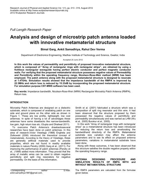
<strong>Analysis</strong> <strong>and</strong> <strong>design</strong> <strong>of</strong> <strong>microstrip</strong> <strong>patch</strong> <strong>antenna</strong> <strong>loaded</strong><br />
<strong>with</strong> innovative metamaterial structure<br />
Bimal Garg, Ankit Samadhiya, Rahul Dev Verma<br />
Department <strong>of</strong> Electronics Engineering, Madhav Institute <strong>of</strong> Technology <strong>and</strong> Science, Gwalior, India<br />
Accepted 20 June 2012<br />
In this work the values <strong>of</strong> permeability <strong>and</strong> permittivity <strong>of</strong> proposed innovative metamaterial structure,<br />
which is composed <strong>of</strong> “Array <strong>of</strong> rectangular rings <strong>with</strong> rectangular strips”, are obtained by using a<br />
fictitious rectangular waveguide having perfect electric conductor <strong>and</strong> perfect magnetic conductor<br />
walls. For verifying that the proposed metamaterial structure possesses negative values <strong>of</strong> Permeability<br />
<strong>and</strong> Permittivity <strong>with</strong>in the operating frequency range, Nicolson-Ross-Weir method (NRW) has been<br />
employed. The <strong>patch</strong> <strong>antenna</strong> along <strong>with</strong> the proposed metamaterial structure is <strong>design</strong>ed to resonate<br />
at 1.47GHz. Simulation results showed that the impedance b<strong>and</strong>width <strong>of</strong> the RMPA is improved by<br />
22.3MHz <strong>and</strong> return loss is reduced by 15.33dB by incorporating the proposed metamaterial structure.<br />
For simulation purpose CST-MWS s<strong>of</strong>tware has been used.<br />
Key words: Impedance b<strong>and</strong>width, Nicolson-Ross-Weir (NRW) Rectangular Microstrip Patch Antenna (RMPA),<br />
Return loss.<br />
INTRODUCTION<br />
Microstrip Patch Antennas are <strong>design</strong>ed on a dielectric<br />
substrate, which is composed <strong>of</strong> aradiating <strong>patch</strong> on one<br />
side <strong>and</strong> ground plane on the other side as shown in<br />
Figure 1. These are low pr<strong>of</strong>ile, lightweight, low cost<br />
<strong>antenna</strong>s. In spite <strong>of</strong> having a lot <strong>of</strong> advantages these<br />
<strong>antenna</strong>s have some drawbacks like narrow-b<strong>and</strong>width,<br />
low gain, high return loss etc. (Gupta <strong>and</strong> Dhaliwal 2011).<br />
To overcome Patch Antenna’s drawbacksseveral<br />
researches have been done on <strong>patch</strong> <strong>antenna</strong>s. In this<br />
area <strong>of</strong> research,Victor Veselago (1968) Engheta <strong>and</strong><br />
Ziolkowski (2006) introduced the theoretical concept <strong>of</strong><br />
metamaterials. According to the theory <strong>of</strong> Veselago, these<br />
are generally artificial materials used to provide<br />
properties, which are not found in readily available<br />
materials in nature Pendry (2000) Garg et al., (2011). For<br />
improving the performance <strong>of</strong> <strong>patch</strong> <strong>antenna</strong>s (Pendry et<br />
al., (1999) added more information. They proved that the<br />
array <strong>of</strong> metallic wires can be used to obtain negative<br />
permittivity <strong>and</strong> split ring resonators for negative<br />
permeability. On the basis <strong>of</strong> this information,<br />
*Corresponding author E-mail:<br />
ankit.samadhiya1987@gmail.com.<br />
Smith et al. (2001) fabricated a structure which was a<br />
composition <strong>of</strong> split ring resonator <strong>and</strong> thin wire. It had<br />
been observed that the structure proposed by them<br />
possessed the negative values <strong>of</strong> permittivity <strong>and</strong><br />
permeability simultaneously <strong>and</strong> was named as LHM (Wu<br />
et al., 2005) Burokur et al., 2005).<br />
In this work “Array <strong>of</strong> rectangular rings <strong>with</strong> rectangular<br />
strips” as a metamaterial structure has been introduced<br />
for reducing the return loss <strong>and</strong> ameliorating the<br />
b<strong>and</strong>width<strong>and</strong> directivity <strong>of</strong> the RMPA. Metamaterial<br />
substrate size variation may affect the <strong>antenna</strong><br />
parameters <strong>and</strong> to see its effect on proposed <strong>antenna</strong><br />
parameters, variations in metamaterial substrate have<br />
been done.<br />
Along <strong>with</strong> these outcomes, it has been observed that<br />
this structure satisfies the double negative property <strong>with</strong>in<br />
the operating frequency range.<br />
ANTENNA DESIGNING PROCEDURE AND<br />
SIMULATION RESULTS OF RMPA WITH <strong>and</strong><br />
WITHOUT METAMATERIAL STRUCTURE<br />
The RMPA parameters are calculated from the formulae<br />
given below.
Garg et al. 014<br />
Figure 1. Microstrip Patch <strong>antenna</strong>.<br />
values have been chosen to obtain the resonating<br />
frequency <strong>of</strong> the proposed <strong>antenna</strong> at 1.47 GHz. These<br />
values can be varied to change the resonating<br />
frequency.The parameter specifications <strong>of</strong> rectangular<br />
<strong>microstrip</strong> <strong>patch</strong> <strong>antenna</strong> are mentioned in Table 1.<br />
Return loss S <strong>and</strong> Impedance B<strong>and</strong>width <strong>of</strong><br />
Rectangular Microstrip Patch Antenna is shown in Figure<br />
3. According to this figure return loss <strong>and</strong> b<strong>and</strong>widthare -<br />
10.447dB <strong>and</strong> 10MHz respectively.<br />
In this paper the proposed metamaterial structure is<br />
introduced to form the superstate <strong>of</strong> a rectangular<br />
<strong>microstrip</strong> <strong>patch</strong> <strong>antenna</strong> (Figure 2). The required<br />
specifications <strong>of</strong> this <strong>design</strong> are shown in the Figure 4.<br />
Desired parametric analysis (Balanis, 1997;Stutzman<br />
<strong>and</strong> Thiele, 1998)<br />
Calculation <strong>of</strong> Width (W)<br />
w =<br />
<br />
<br />
= <br />
<br />
<br />
Where;<br />
c = free space velocity <strong>of</strong> light<br />
ε r = Dielectric constant <strong>of</strong> substrate<br />
……….. (1)<br />
Theeffective dielectric constant <strong>of</strong> the rectangular<br />
<strong>microstrip</strong><strong>patch</strong> <strong>antenna</strong>.<br />
ε = <br />
<br />
+ <br />
<br />
<br />
<br />
The actual length <strong>of</strong> the Patch (L)<br />
…………...(2)<br />
L =L eff - 2ΔL ………………………………… (3)<br />
Where<br />
Leff =<br />
<br />
<br />
…………………………… (4)<br />
Calculation <strong>of</strong> Length Extension<br />
∆<br />
= 0.412 . .<br />
. .<br />
……… …(5)<br />
The Rectangular Microstrip Patch Antenna is <strong>design</strong>ed<br />
onFR-4 lossy substrate <strong>with</strong> ε r = 4.3 <strong>and</strong> height from the<br />
ground plane d= 1.6mm.The Length <strong>and</strong> width <strong>of</strong> RMPA<br />
are L=47.9563mm, W=61.4295mm respectively, which<br />
are calculated from the formulae discussed in parametric<br />
analysis section. For cut width, cut depth, length <strong>of</strong><br />
transmission line <strong>and</strong> width <strong>of</strong> the feed, some specific<br />
Nicolson-Ross-Weir (NRW) approach<br />
The values <strong>of</strong> permittivity <strong>and</strong> permeability affect the<br />
potential parameters like return loss <strong>and</strong> radiation pattern<br />
<strong>of</strong> an <strong>antenna</strong>, this is the reason why these values are<br />
calculated. For obtaining the values <strong>of</strong> permeability <strong>and</strong><br />
permittivity different methods can be used, some <strong>of</strong> them<br />
are Nicolson-Ross-Weir (NRW), NISTiterative, Noniterative<br />
<strong>and</strong> Short circuit techniques. In this work<br />
Nicolson-Ross-Weir (NRW) technique (Mazid et al.,<br />
2008; Ziolkowski, 2003) has been used to obtain the<br />
values <strong>of</strong> permittivity <strong>and</strong> permeability as this is a very<br />
popular technique to convert S-parameters due to the<br />
fact that this technique provides easy as well as effective<br />
formulation <strong>and</strong> calculation. All these methods discussed<br />
above required S-parameters for obtaining the values <strong>of</strong><br />
permeability <strong>and</strong> permittivity.<br />
Here in this work for extracting the S-Parameters,<br />
proposed metamaterial structure is placed between the<br />
two waveguide ports (Hrabar <strong>and</strong> Bartolic, 2003) Hrabar<br />
et al., 2005) at the left <strong>and</strong> right h<strong>and</strong> side <strong>of</strong> the X axis<br />
as shown in Figure 5. In Figure 5, Y-Plane is defined as<br />
Perfect Electric Boundary (PEB) <strong>and</strong> Z-Plane is defined<br />
as the Perfect Magnetic Boundary (PMB), which creates<br />
internal environment <strong>of</strong> waveguide. The simulated S-<br />
Parameters are then exported to Micros<strong>of</strong>t Excel<br />
Program for verifying the Double-Negative properties <strong>of</strong><br />
the proposed metamaterial structure (Garg et al., 2012).<br />
Equations used for calculating permittivity <strong>and</strong><br />
permeability using NRW approach (Garg et al., 2012;<br />
Majid et al., 2009; Samadhiya <strong>and</strong> Verma, 2012)<br />
μ = .( )<br />
…………………………….…… (6)<br />
..( )<br />
Ɛ = .( )<br />
....…………………………….. (7)<br />
..( )<br />
V = S + S …………………………. (8)<br />
V = S − S …………………………. (9)
015 Res. J. Phy. <strong>and</strong> Appl. Sci.<br />
Table 1. RMPA specifications.<br />
Dimensions Unit<br />
Dielectric Constant (ԑr) 4.3 -<br />
Loss Tangent (tan ∂) 0.02 -<br />
Thickness (h) 1.6 mm<br />
Operating Frequency 1.9275 GHz<br />
Length (L) 35.4413 mm<br />
Width (W) 45.6435 mm<br />
Cut Width 5.0 mm<br />
Cut Depth 10.0 mm<br />
Path Length 33.82175 mm<br />
Width Of Feed 3.009 mm<br />
Figure 4. Design <strong>of</strong> proposed metamaterial structure.<br />
Figure 2. Rectangular Patch Antenna at 1.47 GHz.<br />
Figure 5. Proposed metamaterial structure between the two<br />
waveguide ports.<br />
Figure 3. Simulation <strong>of</strong> Return loss S <strong>and</strong> impedance<br />
b<strong>and</strong>width <strong>of</strong> Rectangular Microstrip Patch Antenna.<br />
Where;<br />
εr= Permittivity<br />
μr= Permeability<br />
c= Speed <strong>of</strong> Light<br />
ω = Frequency in Radian<br />
d = Thickness <strong>of</strong> the Substrate<br />
i = Imaginary coefficient<br />
V = Voltage Maxima<br />
V = Voltage Minima<br />
For satisfying Double Negative property, the values <strong>of</strong><br />
permeability <strong>and</strong> permittivity should be negative <strong>with</strong>in<br />
the operating frequency range. The obtained values <strong>of</strong><br />
these two quantities from the MS-Excel Program are<br />
given in Table 2 <strong>and</strong> 3, whereas Figure 6 <strong>and</strong> Figure 7<br />
shows the graph between permeability <strong>and</strong> frequency<br />
<strong>and</strong> permittivity <strong>and</strong> frequency respectively.<br />
Rectangular Microstrip Patch Antenna <strong>with</strong> Proposed<br />
metamaterial is given below in Figure 8.<br />
Return loss S <strong>and</strong> Impedance B<strong>and</strong>width <strong>of</strong> Rectangular<br />
<strong>microstrip</strong> Patch Antenna <strong>with</strong> proposed metamaterial<br />
structure is shown in Figure 9. According to this figure<br />
return loss <strong>and</strong> b<strong>and</strong>width are -25.772dB <strong>and</strong> 32.3MHz<br />
respectively.<br />
From Figure 3 <strong>and</strong> 9 it has been observed that the<br />
return loss has significantly reduced by 15.33 dB <strong>and</strong><br />
b<strong>and</strong>width has increased by 22.3 MHz by incorporating<br />
proposed metamterial structure <strong>with</strong> RMPA.<br />
The radiation pattern <strong>of</strong> an <strong>antenna</strong> is generally its<br />
most basic requirement because it determines the<br />
distribution <strong>of</strong> radiated energy in to the space.Gain<br />
depends on directivity <strong>and</strong> directivity is totally depends on<br />
the shape <strong>of</strong> the radiation patterns <strong>of</strong> an <strong>antenna</strong>. The<br />
Radiation Pattern <strong>of</strong> the RMPA operating at 1.47GHz is<br />
shown in Figure 10. This shows that the directivity is
Garg et al. 016<br />
Table 2.Obtained values for Permeability versus Frequency from the MS-Excel program.<br />
Frequency(GHz) Permeability [µr] Re [µr]<br />
1.4699998 -374.607339659479+3.45618384526422i -374.607<br />
1.472 -366.919300540636+2.86948228882631i -366.919<br />
1.474 -360.018040176235+0.731096575437185i -360.018<br />
1.476 -354.394182884314-2.51093557285303i -354.394<br />
1.4779998 -350.339037560325-6.30143536916735i -350.339<br />
1.4799998 -347.928829930846-10.0203032019875i -347.929<br />
Table 3. Obtained values for Permittivity versus Frequency from the MS-Excel program.<br />
Frequency (GHz) Permittivity [Ɛr] Re [Ɛr]<br />
1.4699998 -29.0168213445691-0.0961040378037559i -29.0168<br />
1.472 -28.3655580620901-0.0176464610117287i -28.3656<br />
1.474 -27.6834397492795+0.0364691431149244i -27.6834<br />
1.476 -26.9840623306393+0.0534416269108215i -26.9841<br />
1.4779998 -26.284494584046+0.0279434158733502i -26.2845<br />
1.4799998 -25.6015651919585-0.0379574358370813i -25.6016<br />
Figure 6. Permeability versus Frequency graph.<br />
Figure 8. Rectangular Microstrip Patch Antenna <strong>with</strong><br />
proposed metamaterial structure.<br />
Figure 7. Permittivity versus frequency graph.<br />
6.575dBi, whereas Figure 11 shows that the directivity <strong>of</strong><br />
the RMPA <strong>with</strong> the proposed metamaterial structure<br />
which is 6.604. These results are showing that there is<br />
amelioration in directivity <strong>of</strong> RMPA by incorporating<br />
proposed metamaterial structure.<br />
Figure 9. Simulation <strong>of</strong> Return Loss S <strong>and</strong><br />
impedance b<strong>and</strong>width <strong>of</strong> RMPA <strong>with</strong> proposed<br />
metamaterial structure.<br />
Smith et al., (2000) charts play a very important role for<br />
an <strong>antenna</strong> as it provides valuable information about
017 Res. J. Phy. <strong>and</strong> Appl. Sci.<br />
Figure 10. Radiation pattern <strong>of</strong> a Rectangular Microstrip Patch<br />
Antenna.<br />
Figure 14. Fabricated rectangular <strong>microstrip</strong> <strong>patch</strong> <strong>antenna</strong> on<br />
PCB.<br />
Figure 11. Radiation pattern <strong>of</strong> RMPA <strong>with</strong> proposed metamaterial<br />
structure.<br />
Figure 15. Fabricated metamaterial structure on PCB.<br />
Figure16. Setup for measurement <strong>of</strong> <strong>antenna</strong> parameters.<br />
Figure 12. Smith chart <strong>of</strong> Rectangular Microstrip Patch Antenna.<br />
Figure17. Combined simulated <strong>and</strong> measured result <strong>of</strong> proposed<br />
<strong>antenna</strong>.<br />
Figure 13. Smith chart <strong>of</strong> RMPA <strong>with</strong> proposed metamaterial<br />
structure.<br />
impedances at different frequency point so that decision<br />
about the impedance matching can be taken. From<br />
Figure 12 <strong>and</strong> 13, it is clear that the RMPA <strong>with</strong> the<br />
proposed metamaterial structure provides better
Garg et al. 018<br />
Table 4. Variation in metamaterial substrate size.<br />
Metamaterial substrate Return B<strong>and</strong>width<br />
size (mm×mm)<br />
Loss (dB) (MHz)<br />
Directivity (dBi)<br />
122.85 ×95.91 -23.923 29 6.806<br />
120 ×94 -31.935 30.5 6.726<br />
118 ×92 -22.041 32.9 6.429<br />
116 ×93.4 -25.923 32.2 6.613<br />
116×93.2 (Proposed size) -25.772 32.3 6.604<br />
124×96 -23.489 28.9 6.809<br />
126 ×98 -22.122 28.5 6.822<br />
impedance matching at 1.47GHz, when compared to<br />
RMPA alone.<br />
In this work metamaterial substrate size has been<br />
varied to see its effect on <strong>patch</strong> <strong>antenna</strong> parameters like<br />
return loss, b<strong>and</strong>width <strong>and</strong> directivity. These variations in<br />
metamaterial substrate size along <strong>with</strong> the values <strong>of</strong><br />
<strong>patch</strong> <strong>antenna</strong> parameters are shown in table 4. Initially<br />
the dimension <strong>of</strong> the metamaterial substrate was<br />
122.85mm ×95.91mm, which is equal to the substrate<br />
size on which <strong>patch</strong> has been <strong>design</strong>ed.It is clear from<br />
the table 4 that, if the metamaterial substrate size is<br />
varied then due to this variation <strong>patch</strong> <strong>antenna</strong><br />
parameters are also varied.<br />
FABRICATION, TESTING AND EXPERIMENTAL<br />
RESULTS<br />
Return loss pattern<strong>of</strong> RMPA <strong>with</strong> the proposed<br />
metamaterial structure <strong>with</strong>in the simulated frequency<br />
range given in Figure9 has been obtained from CST-<br />
MWS s<strong>of</strong>tware, for verifying this result,hardware had<br />
been fabricated on PCB. RMPA <strong>and</strong> proposed<br />
metamaterial structure after fabrication on PCB have<br />
been given in Figure 14 <strong>and</strong> 15.After the fabrication <strong>of</strong><br />
<strong>antenna</strong> the <strong>antenna</strong> parameters like return loss <strong>and</strong><br />
b<strong>and</strong>width are measured on the spectrum analyzer. The<br />
setup which is used for <strong>antenna</strong> parameters<br />
measurement is shown in Figure16.<br />
Figure17 shows the Simulated <strong>and</strong> Measured result <strong>of</strong><br />
proposed <strong>antenna</strong>.According to this graph the return loss<br />
<strong>and</strong> b<strong>and</strong>width at 1.47 GHz are -24.4dB <strong>and</strong> 29.835MHz<br />
(approximately) for fabricated <strong>antenna</strong>. This shows that<br />
there are very less variations in practically measured<br />
results <strong>and</strong> simulated results <strong>of</strong> RMPA incorporated <strong>with</strong><br />
proposed metamaterial structure.<br />
Conclusion<br />
On the basis <strong>of</strong> the simulation results it is observed that<br />
the minimum return loss obtained at the <strong>design</strong> frequency<br />
for the RMPA <strong>with</strong> proposed metamaterial structure is -<br />
25.77 dB <strong>and</strong> b<strong>and</strong>width is 32.3 MHz this is remarkable<br />
improvement in L-b<strong>and</strong> (1-2GHz), when compared to the<br />
results <strong>of</strong> RMPA alone. It is clearly observed that the<br />
return lossb<strong>and</strong>width <strong>and</strong> directivity has improved<br />
significantly by incorporating the proposed metamaterial<br />
structure at 3.2 mm layer from the ground plane <strong>of</strong> the<br />
<strong>antenna</strong>. Along <strong>with</strong> these improvements this<br />
structuresatisfies Double Negative property <strong>with</strong>in the<br />
simulated frequency range.<br />
REFERENCES<br />
Gupta V, Dhaliwal BS (2011). Performance Enhancement <strong>of</strong><br />
RecangularMicrostrip Patch Antenna by Loading Complementary<br />
Split Ring Resonator in the Patch, Inter. J. <strong>of</strong> Elec. Engg. 3 (1):141–<br />
143.<br />
Veselago VG (1968).The electrodynamics <strong>of</strong> substances <strong>with</strong><br />
simultaneously negative values <strong>of</strong> μ <strong>and</strong> ε.Sov. Phys. Uspekhi. 10<br />
(4):509 – 514.<br />
Engheta N, Ziolkowski RW (2006).Metamaterial Physics <strong>and</strong><br />
Engineering Explorations.Wiley-IEEE Press.<br />
Pendry JB (2000). Negative refraction makes a prefect lens.Phys Rev<br />
Lett.85:3966–3969.<br />
Garg B, Tiwari R, Kumar A, Chitransh T (2011). Design <strong>of</strong> factored X<br />
shaped metamaterial structure for enhancement <strong>of</strong> <strong>patch</strong> <strong>antenna</strong><br />
gain.C.S.N.T. 232-235.<br />
Pendry JB, Holden AJ, Robbins DJ, Stewart WJ (1999). Magnetism<br />
from conductors <strong>and</strong> enhanced nonlinear phenomena.IEEE Trans.<br />
Micro Tech. 47(11)2075-2081.<br />
Smith DR, Padilla WJ,Vier DC, Nasser SCN, Schultz S (2000).<br />
Composite medium <strong>with</strong> simultaneously negative permeability <strong>and</strong><br />
permittivity.PhysRev Lett. 84:4184–4187.<br />
Wu BI, Wang W, Pacheco J, Chen X, Grzegorczyk T, Kong JA (2005).A<br />
study <strong>of</strong> using metamaterials as <strong>antenna</strong> substrate to enhance<br />
gain.PIER. 51, 295-328.<br />
Burokur SN, Latrach M, Toutain S (2005).Theoretical Investigation <strong>of</strong> a<br />
Circular Patch Antenna in the Presence <strong>of</strong> a Left-H<strong>and</strong>ed Mematerial.<br />
IEEE Antennas <strong>and</strong> Wireless Propagation Letters. 4:183-186.<br />
Balanis CA (1997).Antenna Theory <strong>and</strong> Design. John Wiley <strong>and</strong> Sons.<br />
Inc.<br />
Stutzman WL, Thiele GA (1998).Antenna Theory <strong>and</strong> Design. John<br />
Wiley <strong>and</strong> Sons, 2nd Ed.<br />
Mazid HA, Rahim MKA, Masri T (2008). Left-h<strong>and</strong>ed metamaterial<br />
<strong>design</strong> for <strong>microstrip</strong> <strong>antenna</strong> application. R.F.M. 218-221.<br />
Ziolkowski RW (2003). Design, fabrication <strong>and</strong> testing <strong>of</strong> double<br />
negative metamaterials. IEEE Transactions on Antennas<br />
<strong>and</strong>Propagation, 51(7): 1516-1529.<br />
Hrabar S, Bartolic J (2003). Backward Wave Propagation in Waveguide<br />
filled <strong>with</strong> Negative Permeability Meta Material.<br />
Antennas<strong>and</strong>Propagation Society International Symposium, 1: 110 –<br />
113.<br />
Hrabar S, Jankovic G, Zivkovic B,Sipus Z(2005). Numerical <strong>and</strong><br />
Experimental Investigation <strong>of</strong> Field Distribution in Waveguide filled<br />
<strong>with</strong> Anisotropic Single Negative Metamaterial.ICEcom.1- 4.<br />
Hrabar S, Bartolic J, Sipus Z (2005). Waveguide miniaturization using
019 Res. J. Phy. <strong>and</strong> Appl. Sci.<br />
uniaxial negative permeability metamaterial. IEEE Transaction on<br />
AntennasPropagation, 53: 110-119.<br />
Garg B, Samadhiya A, Verma RD (2012). Design <strong>of</strong> Double-F<br />
Metamaterial Structure for Enhancing B<strong>and</strong>width <strong>of</strong> Patch Antenna<br />
<strong>with</strong> Negative µ And ε. C.S.N.T, 35-39.<br />
Majid HA, Rahim MKA, Marsi T (2009).Microstrip Antenna gain<br />
enhancement using left-h<strong>and</strong>ed metamaterial structure. P.I.E.R. 8:<br />
235-247.<br />
SamadhiyaA, Verma RD (2012). Design <strong>of</strong> SSRR based Metamaterial<br />
Structure for Amelioration in Patch Antenna Parameters <strong>with</strong><br />
Negative µ <strong>and</strong> ε. International Conference on Electronic<br />
Communication <strong>and</strong> Instrumentation.