Single Side Stitching, an innovative textile ... - Mechanical Engineering
Single Side Stitching, an innovative textile ... - Mechanical Engineering
Single Side Stitching, an innovative textile ... - Mechanical Engineering

Create successful ePaper yourself
Turn your PDF publications into a flip-book with our unique Google optimized e-Paper software.
Computer Controlled, Automated M<strong>an</strong>ufacture of 3D-Braids for Composites.<br />
H. L<strong>an</strong>ger, DaimlerChrysler AG, Research & Technology, Ottobrunn, (D); A. Pickett, <strong>Engineering</strong><br />
Systems International GmbH, Eschborn, (D); B. Obolenski, FEG Textiltechnik Forschungs- und<br />
Entwicklungsgesellschaft mbH, Aachen, (D); H. Schneider, Herzog Flechtmaschinen GmbH & Co.<br />
KG, Oldenburg (D); M. Schneider, Institut für Textiltechnik der RWTH Aachen, Aachen (D); E.<br />
Jacobs, F.A. Kümpers GmbH & Co. KG Rheine (D) (Speaker)<br />
Introduction<br />
3D-Rotary braiding is a further development of the traditional 2D-braiding technique that allows far<br />
greater flexibility in yarn placing <strong>an</strong>d interlacing by moving the bobbins independently <strong>an</strong>d selectively<br />
in a flat array of horngears. In this way this technique allows the production of near netshaped<br />
3D-<strong>textile</strong> preforms with a yarn architecture specifically designed to satisfy required design<br />
criteria.<br />
Today, a pneumatic/electrical driven prototype machine is available that c<strong>an</strong> produce braids in labscale.<br />
A great deal of practical experience has been gained with this machine which was used to<br />
design a new industrial st<strong>an</strong>dard machine.<br />
This paper presents the main results of a consortium of research <strong>an</strong>d industrial partners developing<br />
this technology in the frame of the MaTech project 3D-BRAIDING (03N3036A/0).<br />
This includes the description of the new machine- <strong>an</strong>d machine control concept, of a new CAE<br />
(Computer Aided <strong>Engineering</strong>) platform for braid development inclusively the FEM braiding<br />
simulation <strong>an</strong>d the presentation of specific mech<strong>an</strong>ical properties of 3D-braid reinforced composites<br />
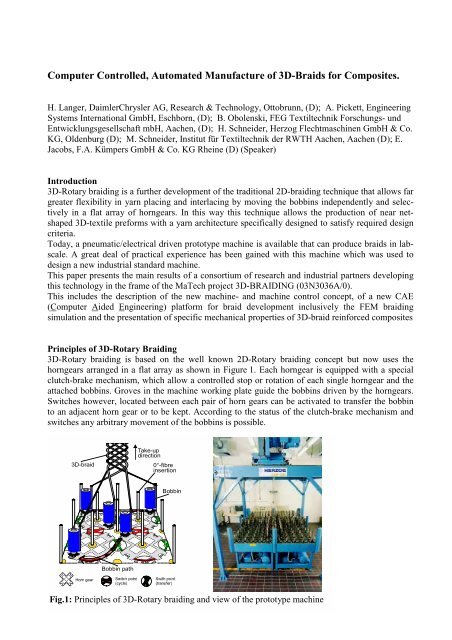
Principles of 3D-Rotary Braiding<br />
3D-Rotary braiding is based on the well known 2D-Rotary braiding concept but now uses the<br />
horngears arr<strong>an</strong>ged in a flat array as shown in Figure 1. Each horngear is equipped with a special<br />
clutch-brake mech<strong>an</strong>ism, which allow a controlled stop or rotation of each single horngear <strong>an</strong>d the<br />
attached bobbins. Groves in the machine working plate guide the bobbins driven by the horngears.<br />
Switches however, located between each pair of horn gears c<strong>an</strong> be activated to tr<strong>an</strong>sfer the bobbin<br />
to <strong>an</strong> adjacent horn gear or to be kept. According to the status of the clutch-brake mech<strong>an</strong>ism <strong>an</strong>d<br />
switches <strong>an</strong>y arbitrary movement of the bobbins is possible.<br />
3D-braid<br />
Bobbin path<br />
Take-up<br />
direction<br />
0°-fibre<br />
insertion<br />
Bobbin<br />
Fig.1: Principles of 3D-Rotary braiding <strong>an</strong>d view of the prototype machine
For the insertion of st<strong>an</strong>ding ends into the braid, those yarns are led through input tubes positioned<br />
between the horngears or through the horngear axles (see Fig.1). In this way it is possible with this<br />
technique to produce braids with almost <strong>an</strong>y fibre orientations <strong>an</strong>d cross-section geometry in near<br />
net-shape with minimum waste. Due to the possibility to ch<strong>an</strong>ge the number of "active" bobbins the<br />
cross-section area <strong>an</strong>d with that the geometry of the braid c<strong>an</strong> be varied online.<br />
CAE Tools for Braid Development Experience has shown that producing a good 3D-braid is such<br />
a complex process that it must be supported by numerical tools. Consequently, four linked software<br />
tools (modules) have been developed to optimise the bobbins movements, visualise <strong>an</strong>d check a<br />
chosen scheme, simulate the braiding process, <strong>an</strong>d finally, <strong>an</strong>alyse the mech<strong>an</strong>ical perform<strong>an</strong>ce of<br />
the composite part. Using these tools the design engineer is able to ‘virtually’ design the braid <strong>an</strong>d<br />
generate <strong>an</strong> output file to control the 3D-Rotary braider. This approach to design allows the design<br />
engineer to optimise ‘virtually’ both the m<strong>an</strong>ufacturing process <strong>an</strong>d final part without resort to<br />
difficult <strong>an</strong>d time consuming testing methods.<br />
The CAE concept with the interaction <strong>an</strong>d the function of the different software tools is explained in<br />
the diagram of Fig.2.<br />
ROUTE<br />
Automatic enumeration of<br />
possible bobbin movements<br />
under defined conditions<br />
CAB<br />
Visualisation of the bobbin<br />
movements (e.g. paths). General<br />
control by the user prints of bobbin<br />
setups etc.<br />
Unsatisfactory design - redesign<br />
PAM-SOLID<br />
1. Dynamic Finite element<br />
simulation of the braiding<br />
process<br />
2. Static <strong>an</strong>d failure <strong>an</strong>alysis of<br />
the <strong>textile</strong> braided composite<br />
Satisfactory design<br />
MANUFACTURE<br />
Generation of output file for the<br />
3D-rotary braider<br />
Fig.2: Interactions of the different software tools <strong>an</strong>d schematic representation of<br />
the process to design virtually 3D-braids<br />
The software tool ROUTE helps to select the best combination of bobbins movements <strong>an</strong>d to activate<br />
as m<strong>an</strong>y bobbins as possible <strong>an</strong>d in this way to maximise the machine efficiency. After the<br />
enumeration of all possible paths for each bobbins under the defined boundary conditions it produces<br />
<strong>an</strong> overall solution based on the compatibility of all paths. The solution c<strong>an</strong> be visualised by<br />
the machine internal Computer Aided Braiding (CAB) simulation software, which acts m<strong>an</strong>ifold.<br />
On the one h<strong>an</strong>d it allows the user to specify the boundary conditions (e.g. bobbin set-up, braid<br />
cross-section geometry, etc.) of the bobbin movement <strong>an</strong>d to create <strong>an</strong>d visualise the bobbin tracks<br />
interactively. On the other h<strong>an</strong>d it creates the machine control files <strong>an</strong>d it generates the informations<br />
about bobbin set-up <strong>an</strong>d movement, which are necessary for the FEM simulation. The tool used<br />
therefore is the commercial FEM software PAM-SOLID, that has been adapted to simulate the<br />
braiding process. A dynamic simulation of the braiding process give a detailed prediction of the<br />
yarn architecture in the braid which then is used as a basis for a meso-mech<strong>an</strong>ical stiffness <strong>an</strong>alysis.<br />
2
FEM-Simulation of the 3D-Braiding Process<br />
Simulation of the braiding process is a difficult application for finite element <strong>an</strong>alysis. The calculation<br />
must permit very large displacements <strong>an</strong>d a highly efficient contact algorithm is essential to<br />
treat the enormous amount of yarn interaction. Some special features are also needed such as <strong>an</strong><br />
element to model the ‘feed-in’ <strong>an</strong>d ‘feed-out’ of yarn from the bobbin as it tr<strong>an</strong>sverses the base<br />
plate. The key features of a braiding FE model are shown in Figure 3. The yarns are represented as<br />
a fine mesh of bar (or membr<strong>an</strong>e) elements with a typical length of 2 mm so that fine details of the<br />
braid may be captured. All nodes at the braid point are moved vertically with a const<strong>an</strong>t ‘take-up’<br />
velocity <strong>an</strong>d each node at the lower end is assigned a velocity time history to describe the motion of<br />
the bobbin it represents. Stationary yarns are similarly modelled except that their lower nodes are<br />
held fixed. The yarns are given typical material properties <strong>an</strong>d the special elements at the base,<br />
which represent the bobbins, are given a force-deflection behaviour that corresponds to the ‘feedout’<br />
<strong>an</strong>d ‘feed-in’ of yarn from the bobbin. Finally, potential contact, with friction, is defined for all<br />
yarns so that this may be identified <strong>an</strong>d treated.<br />
take-up<br />
velocity<br />
bobbin path<br />
braiding point<br />
(110 mm, 220 mm, 700 mm)<br />
stationary thread<br />
braiding thread<br />
220 mm<br />
bobbin element<br />
bar elements<br />
node j+1<br />
node j+2, j+3<br />
horn gear<br />
velocity<br />
node j<br />
bar n+1<br />
bar n<br />
bar n-1<br />
membr<strong>an</strong>e elements<br />
node j+1, j<br />
membr<strong>an</strong>e n+1<br />
membr<strong>an</strong>e n<br />
membr<strong>an</strong>e n-1<br />
Fig.3: Key features for the finite element<br />
modelling of 3D-braiding using bar <strong>an</strong>d<br />
membr<strong>an</strong>e elements<br />
Braiding<br />
needles<br />
Fig.4: Simulation of a rect<strong>an</strong>gular braid using<br />
membr<strong>an</strong>e elements<br />
The simulation result using membr<strong>an</strong>e elements is shown in Figure 4 for a rect<strong>an</strong>gular braid. A generally<br />
good interaction of the yarns is obtained <strong>an</strong>d the contact between the yarns is seen to function<br />
well. These results allow the motion of yarns <strong>an</strong>d their final positions to be studied <strong>an</strong>d other valuable<br />
information, such as the total feed-out of yarn from each bobbin, to be predicted. Variations in<br />
bobbin tensile force, braid take-up velocity <strong>an</strong>d alternative braiding schemes may be easily simulated<br />
<strong>an</strong>d assessed.<br />
Mech<strong>an</strong>ical <strong>an</strong>alysis of braided composites<br />
From the braiding simulation a detailed model of yarn architecture is obtained which could provide<br />
a basis for a mech<strong>an</strong>ical <strong>an</strong>alysis of the <strong>textile</strong> reinforced composite. The approach being investigated<br />
is to extract a representative section of the braid from the virtual model which is then overlaid<br />
with a mesh of solid elements to approximate the matrix resin. These two independent finite element<br />
meshes are modified <strong>an</strong>d coupled via constraint equations.<br />
This level of modelling is at the ‘meso-’ scale which c<strong>an</strong> give a good local prediction of stress <strong>an</strong>d<br />
strain distribution within each constituent material. The model will correctly capture the effects of<br />
the <strong>an</strong>isotropic yarn reinforcement <strong>an</strong>d, furthermore, should provide a sound basis for failure pre-<br />
3
diction if appropriate failure criteria c<strong>an</strong> be identified for the fibre <strong>an</strong>d matrix parts. Indeed m<strong>an</strong>y of<br />
the inherent difficulties of composite macro-failure models, which try to characterise different<br />
failure modes of the combined constituents under different loading conditions, could be overcome<br />
using this level of modelling. That is, each constituent has a me<strong>an</strong>ingful measure of stress <strong>an</strong>d strain<br />
distribution that c<strong>an</strong> be used in its own failure law.<br />
The following Figure 5 shows typical results for the tensile loading to failure of the model .<br />
Location where<br />
critical fibres<br />
break internally<br />
Location of<br />
final fibre <strong>an</strong>d<br />
matrix rupture<br />
Fig.: 5 Meso-mech<strong>an</strong>ical model for stiffness <strong>an</strong>d failure prediction<br />
Internal fibre breakage<br />
(maximum load)<br />
Subsequent<br />
Matrix<br />
failure<br />
Adv<strong>an</strong>ced Machine Concept<br />
The new 3D-braiding machine, developed during this project, still is based on the main principles of<br />
3D-braiding as realised in the available prototype machine. Of course it was tried to eliminate all<br />
technical deficits recognised during the operation of the prototype machine <strong>an</strong>d to improve its functionality.<br />
The main innovations are:<br />
- vertical orientation of the machine working surface <strong>an</strong>d resulting horizontal alignment of the<br />
carriers <strong>an</strong>d yarn bobbins axis<br />
- the machine body consists out of 9 segments, each build up of 16 so called horngear modules,<br />
i.e.: 144 horngear modules in total.<br />
- each horngear is driven by its own servo gearmotor which allows a ch<strong>an</strong>ge of the direction of<br />
rotation of each single horngear <strong>an</strong>d a max speed up to. 60 rpm.<br />
- all horngear modules are fitted with new developed double-torque-clutches which prevent <strong>an</strong>y<br />
damage of the gearmotor in case of a carrier crash.<br />
- if necessary the 9 segments of the machine body easily c<strong>an</strong> be arr<strong>an</strong>ged according to the<br />
geometric shapes of the braids to be produced, e.g. L-, T- etc. or O-shape for overbraiding of<br />
simple m<strong>an</strong>drels or cores<br />
- the horizontal take-off of the braid is realised by a winch system with integrated pl<strong>an</strong>etary gear<br />
to vary the speed.<br />
- updated CAB software package for development of machine control files <strong>an</strong>d visualisation of<br />
bobbin movement <strong>an</strong>d track; additional function for generation of basic bobbin set-ups for free<br />
selectable braid cross sections.<br />
For large scale braid production the bobbin carriers must work perfect. Beside the prevention of<br />
fibre damage, which especially occurs if braiding brittle multifilament carbon rovings, easy <strong>an</strong>d<br />
time saving set-up, bobbin ch<strong>an</strong>ge <strong>an</strong>d threading has to be possible. The most import<strong>an</strong>t innovations<br />
realised to fulfil this requirements are:<br />
4
- optimised thread guides minimise fibre damage<br />
- easy to h<strong>an</strong>dle 4 step yarn tension regulation (250, 400, 550 <strong>an</strong>d 800g)<br />
- integrated carrier guide shoes for rapid carrier feed in during set-up<br />
- time saving bobbin ch<strong>an</strong>ge <strong>an</strong>d easy threading of fibres<br />
- yarn breakage <strong>an</strong>d bobbin run out control by integrated optical sensor<br />
In the following figure 6 the design drawing of the complete new "horizontal" machine is shown.<br />
Fig. 6: Adv<strong>an</strong>ced machine concept<br />
Braiding-Die- Take-Off-<br />
Braiding machine Braiding-Die-Unit Take-Off Unit<br />
Multi-Sensoric Control System<br />
For efficient automatic operation of the 3D-braiding machine a suitable control system is necessary.<br />
Under this aspect a control system was developed for the supervision of the carrier position, for<br />
detection of breakage of all yarns -st<strong>an</strong>ding ends as well as all moving yarns <strong>an</strong>d the control for run<br />
out bobbin at each carrier. The special challenge regarding the development of this new control<br />
system was the large number of elements to be controlled. Furthermore the modular machine concept<br />
should not be restricted in <strong>an</strong>y kind.<br />
An <strong>an</strong>alysis of various control techniques soon showed the adv<strong>an</strong>tages of <strong>an</strong> intelligent solution on<br />
optical basis. Figure 7 shows the basic principles <strong>an</strong>d the realised hardware components of the new,<br />
non-contact multi-sensoric control system.<br />
frame of the<br />
3D-braider<br />
FEG<br />
Camera<br />
Framegrabber<br />
PC<br />
CANcontroller<br />
nominal data<br />
error message<br />
horn gears resp.<br />
st<strong>an</strong>ding- <strong>an</strong>d braiding threads<br />
96 light guides<br />
per machine segment<br />
picture recording<br />
image <strong>an</strong>alysis; comparison of<br />
nominal / actual data<br />
FEG-Camera<br />
<strong>an</strong>d optical<br />
system<br />
Fig. 7: Principle <strong>an</strong>d components of the developed multi-sensoric control system<br />
Compact IPC with<br />
integrated integrated CAN-Bus<br />
Light<br />
Guides<br />
5
For each machine segment compact units were developed with 96 flexible light guides which are<br />
led to the predestinied positions in the machine frame. If the carriers move over this stationary<br />
measuring points they cast shadow upon the open ends of the optical guides. This signals are used<br />
to control the carrier positions. Information about the actual condition of the yarn (ok or broken<br />
respectively. run out) on each moving carrier are tr<strong>an</strong>sferred in the same way from the new developed<br />
carrier with integrated light guides to the stationary measuring points.<br />
All 96 single sensors are joined in a specially developed adapter <strong>an</strong>d brought on the high-resolution<br />
matrix-chip of <strong>an</strong> asynchronous CCD-camera via <strong>an</strong> optical input element. With the aid of a frame<br />
grabber this picture is digitised <strong>an</strong>d evaluated in a compact industry PC. With a special learning<br />
program the position of each sensor c<strong>an</strong> be detected fully automatically, so that <strong>an</strong> assignment of<br />
the single sensors resp. light guide ends is not necessary. The interface to the machine control has<br />
been realised by CAN-Bus. The nominal data of each single machine segment are tr<strong>an</strong>sferred to the<br />
control system via CAN-Bus. After the internal comparison of nominal/actual data in the multi-sensoric<br />
system only the error message with detailed information of kind <strong>an</strong>d position of error is<br />
returned to the machine control.<br />
Examples of realised 3D-braids<br />
After a phase of intensive work to solve basic problems (fibre damage, occurrence of pre-braids)<br />
recognised during braiding technical fibres as carbon or glass, braids were realised for different<br />
applications. The most serious restriction in the selection of the application examples were based on<br />
the limited cross-section areas to be realised with the available prototype machine. Areas of 200 to<br />
300 mm² are in general are to low for aeronautic or automotive structural structures .<br />
Two examples of 3D-braided fibre preforms are shown in figure 8.<br />
87 mm<br />
40 mm<br />
Fig.8: 3D-braided axle with varying cross-section for a compressor stator v<strong>an</strong>e<br />
<strong>an</strong>d T-profile for application in stiffened p<strong>an</strong>el<br />
In the braided fibre preform for <strong>an</strong> axle of a compressor stator v<strong>an</strong>e two tr<strong>an</strong>sition zones of the<br />
cross-section geometry were realised. This was done by taking out part of the braiding yarns of the<br />
process <strong>an</strong>d ch<strong>an</strong>ging the geometry online from round to rect<strong>an</strong>gular. The unused fibres have to be<br />
removed before impregnation. In this way a better coupling of the aerodynamic blade to the axle is<br />
guar<strong>an</strong>teed. Furthermore different T-profiles were m<strong>an</strong>ufactured for reinforcement for p<strong>an</strong>els as<br />
they are used in aeropl<strong>an</strong>e structures. An example too is shown in fig 8. The profile was realised<br />
with a set-up of 111 braiding yarns (24K carbon fibre roving) <strong>an</strong>d 50 st<strong>an</strong>ding yarns (2x24K carbon<br />
fibre rovings) yarns. For the actual prototype machine bobbin set-ups of this r<strong>an</strong>ge at the moment<br />
are the limit with respect to profile dimension.<br />
6
Impregnation<br />
For cost saving production of composites efficient impregnation process are as import<strong>an</strong>t as the<br />
development of efficient <strong>textile</strong> processes. For the impregnation of complex structures costly tools<br />
are necessary if using st<strong>an</strong>dard techniques as e.g. RTM impregnation. Especially during the early<br />
phase of structure development with a lot of geometric ch<strong>an</strong>ges, impregnation techniques without<br />
expensive tool costs are adv<strong>an</strong>tageous. Under this aspects a new membr<strong>an</strong>e assisted impregnation<br />
technique was developed. In the following figure 9 the principles of the new technique are shown<br />
schematically.<br />
resin flow promotor<br />
resin conduit<br />
microporous membr<strong>an</strong>e<br />
evacuation chamber<br />
infiltration/reaction chamber<br />
vacuum resin<br />
Fig. 9 Principles of Membr<strong>an</strong>e Assisted Resin Infusion<br />
Mech<strong>an</strong>ical properties of 3D-braids<br />
The great complexity <strong>an</strong>d variety of possible moving pattern in 3D-braiding makes it almost impossible<br />
to describe the mech<strong>an</strong>ical properties of the composites reinforced with such braids homogeneous<br />
<strong>an</strong>d complete. In general 3D-braid reinforced composites show minor stiffness <strong>an</strong>d strength<br />
120<br />
100<br />
80<br />
60<br />
40<br />
20<br />
0<br />
25 33<br />
83<br />
103 100 102<br />
85 96<br />
87<br />
89<br />
90<br />
84<br />
80<br />
82<br />
62 70<br />
56<br />
37<br />
67<br />
66<br />
61<br />
62<br />
57<br />
46<br />
65<br />
67<br />
55<br />
57<br />
59<br />
21 20 20 32<br />
Weight specific Energy Absorption [kJ/kg]<br />
of 10x10 mm2 Profiles<br />
56<br />
59<br />
53<br />
50 61<br />
58 65<br />
65<br />
20 24<br />
Non crimp fabric, stitched (65kJ/kg)<br />
3D-braid, aramid / carbon, 34° (63kJ/kg)<br />
Prepreg, unidirectional (58 kJ/kg)<br />
Non crimp fabric, unstitched (25 kJ/kg)<br />
3D-braid, carbon / carbon, 48° (97kJ/kg)<br />
3D-braid, aramid / micro rods, 30° (84 kJ/kg)<br />
3D-braid<br />
Non crimp fabric (2,5D)<br />
stitched<br />
UD-Prepreg (1D)<br />
Non crimp fabric (2D)<br />
unstitched<br />
Fig. 10: Weight specific energy absorption of 3D-braid reinforced composites<br />
<strong>an</strong>d comparison with non 3D-fibre structures<br />
7
properties compared with unidirectional prepreg or non crimp-fabric constructions. This depends of<br />
course on the differences in the structure of the fibre reinforcement, the perfectly straight oriented<br />
fibres in prepregs or non-crimp fabrics <strong>an</strong>d the interlaced fibre structure of the 3D-braids. Due to<br />
the process even the st<strong>an</strong>ding threads are inserted in the braid with more or less waviness <strong>an</strong>d not<br />
straight as expected. Exactly this fibre orientation on the other h<strong>an</strong>d is responsible for a high damage<br />
toler<strong>an</strong>ce <strong>an</strong>d <strong>an</strong> excellent energy absorption behaviour of such composite structures.<br />
In the above figure 10 values of the specific energy absorption, measured in crash tests, are listed<br />
for different 3D-braided fibre structures <strong>an</strong>d compared with fibre reinforced materials out of prepregs<br />
<strong>an</strong>d non-crimp fabrics (with <strong>an</strong>d without stitching). Maximum energy absorption values up to<br />
about 100J/g are reached with carbon fibre 3D-braids (braiding <strong>an</strong>gle 48°, Tenax HTA 5331, 12K).<br />
A comparison with metals, which reach values in the r<strong>an</strong>ge of 10 to 30 J/g, demonstrate impressively<br />
the potential of 3D-braid reinforced composites in the field of crash absorbing structures.<br />
Costs of 3D-braids<br />
To evaluate <strong>an</strong>d <strong>an</strong>alyse the costs of 3D-Rotary braiding structures, a lot of investigations have been<br />
done. The whole production process, including time for preparation, was <strong>an</strong>alysed for inst<strong>an</strong>ce by<br />
REFA-methods. Weak spots regarding the stability of the process, the sequence of the different<br />
production steps <strong>an</strong>d the h<strong>an</strong>dling in general were shown <strong>an</strong>d because of this the consortium was<br />
able to find solutions for optimisation with respect to control systems, automation <strong>an</strong>d simplifying<br />
the h<strong>an</strong>dling. So the efficiency for example of the production of a T-profile could be increased from<br />
40% to 65% <strong>an</strong>d the productivity for about 50%. Due to this, the price of such a profile could be<br />
less th<strong>an</strong> 1/3 of the price when starting this project.<br />
Conclusion<br />
The deficits of 3D-rotary braiding concerning fibre damage <strong>an</strong>d pre-braiding at the beginning of the<br />
project were largely solved by machine <strong>an</strong>d bobbin carrier modifications <strong>an</strong>d the integration of<br />
braiding needles. For the very complex task to develop optimised bobbin set-ups <strong>an</strong>d moving patterns<br />
a CAE concept inclusively the suitable software tools was developed. In this way a virtual<br />
design of braids is possible. The whole evaluation concept for 3D-braids was completed by <strong>an</strong> FEM<br />
simulation tool. In this way the braiding process which delivers results on the generated fibre<br />
structures (orientation <strong>an</strong>d position of each single yarn in 3D-space) c<strong>an</strong> be simulated <strong>an</strong>d the prediction<br />
of the mech<strong>an</strong>ical properties of the final composites is possible.<br />
For the impregnation of the fibre preforms a membr<strong>an</strong>e assisted resin infusion process with a high<br />
potential for saving tool costs was developed <strong>an</strong>d tested. The mech<strong>an</strong>ical properties of the 3D-braid<br />
reinforced composites suffer from reduced strength <strong>an</strong>d stiffness properties compared with conventional<br />
straight fibre reinforcements, but guar<strong>an</strong>tee on the other h<strong>an</strong>d high damage toler<strong>an</strong>ce, structural<br />
integrity <strong>an</strong>d <strong>an</strong> excellent specific energy absorption behaviour. Measured values of up to 100<br />
J/g demonstrate the potential of this property compared with metals, which are in the r<strong>an</strong>ge of 10 -<br />
30 J/g. The application of 3D-braiding at the moment limited by the small cross-section areas which<br />
are realisable with the actual prototype machine.<br />
Based on the experience with this machine a new industrial st<strong>an</strong>dard 3D-braiding machine was<br />
designed <strong>an</strong>d m<strong>an</strong>ufactured during this project. With <strong>an</strong> increased number of horngears (144 instead<br />
of 100), each single motor driven <strong>an</strong>d <strong>an</strong> integrated multi-sensoric control system the productivity<br />
of the process should clearly be increased <strong>an</strong>d the field of applications extended. However further<br />
developments are necessary, especially in the automation of still time consuming processes as bobbin<br />
set-up <strong>an</strong>d -ch<strong>an</strong>ge should be realised in the near future to establish this powerful <strong>textile</strong> technique<br />
in the field of composites.<br />
8