Single Side Stitching, an innovative textile ... - Mechanical Engineering
Single Side Stitching, an innovative textile ... - Mechanical Engineering
Single Side Stitching, an innovative textile ... - Mechanical Engineering

You also want an ePaper? Increase the reach of your titles
YUMPU automatically turns print PDFs into web optimized ePapers that Google loves.
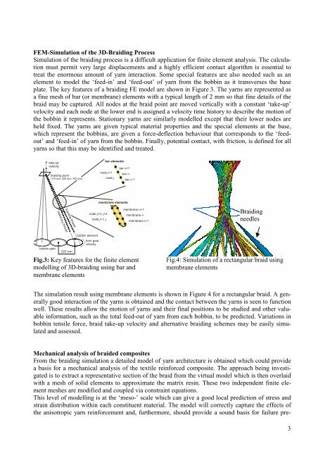
FEM-Simulation of the 3D-Braiding Process<br />
Simulation of the braiding process is a difficult application for finite element <strong>an</strong>alysis. The calculation<br />
must permit very large displacements <strong>an</strong>d a highly efficient contact algorithm is essential to<br />
treat the enormous amount of yarn interaction. Some special features are also needed such as <strong>an</strong><br />
element to model the ‘feed-in’ <strong>an</strong>d ‘feed-out’ of yarn from the bobbin as it tr<strong>an</strong>sverses the base<br />
plate. The key features of a braiding FE model are shown in Figure 3. The yarns are represented as<br />
a fine mesh of bar (or membr<strong>an</strong>e) elements with a typical length of 2 mm so that fine details of the<br />
braid may be captured. All nodes at the braid point are moved vertically with a const<strong>an</strong>t ‘take-up’<br />
velocity <strong>an</strong>d each node at the lower end is assigned a velocity time history to describe the motion of<br />
the bobbin it represents. Stationary yarns are similarly modelled except that their lower nodes are<br />
held fixed. The yarns are given typical material properties <strong>an</strong>d the special elements at the base,<br />
which represent the bobbins, are given a force-deflection behaviour that corresponds to the ‘feedout’<br />
<strong>an</strong>d ‘feed-in’ of yarn from the bobbin. Finally, potential contact, with friction, is defined for all<br />
yarns so that this may be identified <strong>an</strong>d treated.<br />
take-up<br />
velocity<br />
bobbin path<br />
braiding point<br />
(110 mm, 220 mm, 700 mm)<br />
stationary thread<br />
braiding thread<br />
220 mm<br />
bobbin element<br />
bar elements<br />
node j+1<br />
node j+2, j+3<br />
horn gear<br />
velocity<br />
node j<br />
bar n+1<br />
bar n<br />
bar n-1<br />
membr<strong>an</strong>e elements<br />
node j+1, j<br />
membr<strong>an</strong>e n+1<br />
membr<strong>an</strong>e n<br />
membr<strong>an</strong>e n-1<br />
Fig.3: Key features for the finite element<br />
modelling of 3D-braiding using bar <strong>an</strong>d<br />
membr<strong>an</strong>e elements<br />
Braiding<br />
needles<br />
Fig.4: Simulation of a rect<strong>an</strong>gular braid using<br />
membr<strong>an</strong>e elements<br />
The simulation result using membr<strong>an</strong>e elements is shown in Figure 4 for a rect<strong>an</strong>gular braid. A generally<br />
good interaction of the yarns is obtained <strong>an</strong>d the contact between the yarns is seen to function<br />
well. These results allow the motion of yarns <strong>an</strong>d their final positions to be studied <strong>an</strong>d other valuable<br />
information, such as the total feed-out of yarn from each bobbin, to be predicted. Variations in<br />
bobbin tensile force, braid take-up velocity <strong>an</strong>d alternative braiding schemes may be easily simulated<br />
<strong>an</strong>d assessed.<br />
Mech<strong>an</strong>ical <strong>an</strong>alysis of braided composites<br />
From the braiding simulation a detailed model of yarn architecture is obtained which could provide<br />
a basis for a mech<strong>an</strong>ical <strong>an</strong>alysis of the <strong>textile</strong> reinforced composite. The approach being investigated<br />
is to extract a representative section of the braid from the virtual model which is then overlaid<br />
with a mesh of solid elements to approximate the matrix resin. These two independent finite element<br />
meshes are modified <strong>an</strong>d coupled via constraint equations.<br />
This level of modelling is at the ‘meso-’ scale which c<strong>an</strong> give a good local prediction of stress <strong>an</strong>d<br />
strain distribution within each constituent material. The model will correctly capture the effects of<br />
the <strong>an</strong>isotropic yarn reinforcement <strong>an</strong>d, furthermore, should provide a sound basis for failure pre-<br />
3