PGP/PGM300 Series PGP/PGM400 Series - Siebert Hydraulik ...
PGP/PGM300 Series PGP/PGM400 Series - Siebert Hydraulik ...
PGP/PGM300 Series PGP/PGM400 Series - Siebert Hydraulik ...

You also want an ePaper? Increase the reach of your titles
YUMPU automatically turns print PDFs into web optimized ePapers that Google loves.
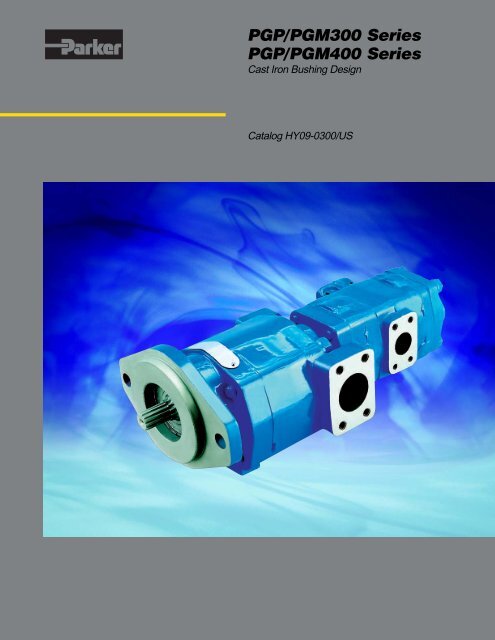
<strong>PGP</strong>/<strong>PGM300</strong> <strong>Series</strong><br />
<strong>PGP</strong>/<strong>PGM400</strong> <strong>Series</strong><br />
Cast Iron Bushing Design<br />
Catalog HY09-0300/US
Catalog HY09-0300/US<br />
General Information<br />
The Parker Hannifin<br />
Gear Pump Division<br />
Assures:<br />
! Consistent quality<br />
! Technical innovation<br />
! Premier customer service<br />
Worldwide Sales<br />
and Service<br />
Parker operates sales and service<br />
centers in major industrial areas<br />
worldwide. Call 1-800-C-PARKER for<br />
more information, or for a synopsis<br />
of the Gear Pump Division, contact a<br />
Parker representative.<br />
<strong>PGP</strong>/<strong>PGM300</strong> <strong>Series</strong>, <strong>PGP</strong>/<strong>PGM400</strong> <strong>Series</strong><br />
Cast Iron Bushing Design<br />
The Gear Pump Division’s ability to<br />
engineer specialty products for unique<br />
applications has kept us at the forefront<br />
of technology, and ensured our position<br />
as the industry leader. Our success has<br />
come from providing a quality product<br />
with excellent sales and service support.<br />
We manufacture hydraulic components<br />
for a wide range of industries including:<br />
• Material Handling<br />
• Construction<br />
• Turf Care<br />
• Forestry<br />
• Agriculture<br />
• Industrial<br />
!<br />
WARNING<br />
FAILURE OR IMPROPER SELECTION OR IMPROPER USE OF THE PRODUCTS AND/OR SYSTEMS DESCRIBED HEREIN OR RELATED ITEMS CAN CAUSE DEATH, PERSONAL<br />
INJURY AND PROPERTY DAMAGE.<br />
This document and other information from Parker Hannifin Corporation, its subsidiaries and authorized distributors provide product and/or system options for further investigation by users<br />
having technical expertise. It is important that you analyze all aspects of your application and review the information concerning the product or system in the current product catalog. Due<br />
to the variety of operating conditions and applications for these products or systems, the user, through its own analysis and testing, is solely responsible for making the final selection of<br />
the products and systems and assuring that all performance, safety and warning requirements of the application are met.<br />
The products described herein, including without limitation, product features, specifications, designs, availability and pricing, are subject to change by Parker Hannifin Corporation and its<br />
subsidiaries at any time without notice.<br />
Offer of Sale<br />
The items described in this document are hereby offered for sale by Parker Hannifin Corporation, its subsidiaries or its authorized distributors. This offer and its acceptance are governed<br />
by the provisions stated in the “Offer of Sale”.<br />
© Copyright 2003, Parker Hannifin Corporation, All Rights Reserved.<br />
2<br />
Parker Hannifin Corporation<br />
Gear Pump Division<br />
Youngstown, Ohio USA
Catalog HY09-0300/US<br />
Table of Contents<br />
<strong>PGP</strong>/<strong>PGM300</strong> <strong>Series</strong>, <strong>PGP</strong>/<strong>PGM400</strong> <strong>Series</strong><br />
Cast Iron Bushing Design<br />
<strong>PGP</strong>/<strong>PGM300</strong> <strong>Series</strong><br />
Ordering Information ............................................. 4<br />
General Information ............................................ 12<br />
PL Factor ........................................................... 13<br />
General Data ...................................................... 14<br />
Porting ............................................................... 15<br />
Drive Shaft ......................................................... 15<br />
Performance Curves ........................................... 16<br />
Dimensional Data ............................................... 17<br />
<strong>PGP</strong>/PGM315 <strong>Series</strong> Pump Performance Data ... 18<br />
<strong>PGP</strong>/PGM330 <strong>Series</strong> Pump Performance Data ... 19<br />
<strong>PGP</strong>/PGM350 <strong>Series</strong> Pump Performance Data ... 20<br />
<strong>PGP</strong>/PGM365 <strong>Series</strong> Pump Performance Data ... 21<br />
<strong>PGP</strong>/<strong>PGM400</strong> <strong>Series</strong><br />
Dimensional Data ............................................... 22<br />
Special Assemblies ............................................. 24<br />
Offer of Sale ....................................................... 26<br />
3<br />
Parker Hannifin Corporation<br />
Gear Pump Division<br />
Youngstown, Ohio USA
Catalog HY09-0300/US<br />
<strong>PGP</strong>/PGM315 <strong>Series</strong> - Coding<br />
<strong>PGP</strong>/PGM315 <strong>Series</strong> Coding<br />
(1)<br />
(2) (3) (4) (5) (6) (7) (8)<br />
<strong>PGP</strong>/<strong>PGM300</strong> <strong>Series</strong>, <strong>PGP</strong>/<strong>PGM400</strong> <strong>Series</strong><br />
Cast Iron Bushing Design<br />
Tandem: Repeat if Necessary<br />
(9) (6) (7) (10)<br />
P<br />
G<br />
3 1 5<br />
Pump/Motor (1)<br />
P Pump (PE for<br />
fluorocarbon seals)<br />
M Motor (no tandem<br />
motors available)<br />
Port End Cover (5)<br />
Unit (2)<br />
A Single Unit<br />
B Tandem Unit (flush studs)<br />
L Unit with Extended Studs<br />
Shaft End Cover (3)<br />
1 Pump, cw w/o<br />
O.B. bearing<br />
2 Pump, ccw w/o<br />
O.B. bearing<br />
4 Pump, cw with O.B.<br />
bearing (Code 490 Only)<br />
5 Pump, ccw with O.B.<br />
bearing (Code 590 Only)<br />
9 Motor, bi-rot w/o O.B.<br />
bearing + 1/4" ODT drain<br />
Shaft End Cover (4)<br />
89 SAE 2 bolt for clutch<br />
90 4 bolt 72x100mm<br />
80mm pilot<br />
93 SAE “A" 2 bolt<br />
95 Pad Mount for Clutch<br />
96 SAE “B" 2 bolt<br />
Gear Housing (6)<br />
AB Pump<br />
EB Motor<br />
(Side Ported)<br />
IN OUT CW CCW<br />
• • • •<br />
SAE Split Flange (pump)<br />
1" 3/4" EJ JE<br />
1" 1/2" EK KE<br />
3/4" 3/4" EL LE<br />
3/4" 1/2" EM ME<br />
1" - OE EO<br />
3/4" - OF FO<br />
- 3/4" OJ JO<br />
- 1/2" OL LO<br />
SAE Split Flange (motor)<br />
1" 1" DR-Double<br />
3/4" 3/4" DS-Double<br />
National Pipe Thread (pump)<br />
1-1/4" 1" AJ JA<br />
1-1/4" 3/4" AK KA<br />
1" 1" AL LA<br />
1" 3/4" AM MA<br />
3/4" 3/4" AR RA<br />
National Pipe Thread (motor)<br />
1" 1" DM-Double<br />
3/4" 3/4" DN-Double<br />
1/2" 1/2" DQ-Double<br />
Unported (pump)<br />
BI Unported<br />
OD Tube Porting (pump)<br />
1-1/4" 1" FB BF<br />
1-1/4" 7/8" FC CF<br />
1-1/4" 3/4" FG GF<br />
1-1/4" 5/8" FJ JF<br />
1" 1" FL LF<br />
1" 7/8" FV VF<br />
1" 3/4" FW WF<br />
1" 5/8" FX XF<br />
7/8" 7/8" FY YF<br />
7/8" 3/4" FZ ZF<br />
7/8" 5/8" BC CB<br />
7/8" 1/2" BG GB<br />
3/4" 3/4" BJ JB<br />
3/4" 5/8" BL LB<br />
3/4" 1/2" BN NB<br />
1 1/4" - BV VB<br />
1" - BW WB<br />
7/8" - BX XB<br />
3/4" - BY YB<br />
- 1" BZ ZB<br />
- 7/8" PD DP<br />
- 3/4" PE EP<br />
- 5/8" PM MP<br />
- 1/2" PN NP<br />
(Side Ported) (cont.)<br />
IN OUT CW CCW<br />
• • • •<br />
OD Tube Porting (motor)<br />
1" 1" VN-Double<br />
3/4" 3/4" VR-Double<br />
1/2" 1/2" VQ-Double<br />
BSPP Porting (pump)<br />
1-1/4" 1" FN NF<br />
1-1/4" 7/8" FP PF<br />
1-1/4" 3/4" FR RF<br />
1" 1" FS SF<br />
1" 7/8" FT TF<br />
1" 3/4" BP PB<br />
7/8" 7/8" BQ QB<br />
7/8" 3/4" BR RB<br />
7/8" 1/2" BT TB<br />
3/4" 3/4" BU UB<br />
3/4" 1/2" PQ QP<br />
1-1/4" - PR RP<br />
1" - PS SP<br />
7/8" - PT TP<br />
3/4" - PV VP<br />
- 1" PW WP<br />
- 7/8" PX XP<br />
- 3/4" PY YP<br />
- 1/2" PZ ZP<br />
BSPP Porting (motor)<br />
1" 1" VY-Double<br />
3/4" 3/4" VZ-Double<br />
1/2" 1/2" VV-Double<br />
Metric Split Flange (pump)<br />
1" 3/4" EV VE<br />
1" 1/2" EW WE<br />
3/4" 3/4" EX XE<br />
3/4" 1/2" EY YE<br />
1" 0" OP PO<br />
3/4" 0" OR RO<br />
0" 3/4" OT TO<br />
0" 1/2" OV VO<br />
Metric Split Flange (motor)<br />
1" 1" DV-Double<br />
3/4" 3/4" DW-Double<br />
(Rear Ported)<br />
IN OUT CW CCW<br />
• • • •<br />
OD Tube Porting (pump)<br />
1-1/4" 1" UC CU<br />
1-1/4" 7/8" UF FU<br />
1-1/4" 3/4" UN NU<br />
1" 1" UD DU<br />
1" 7/8" UP PU<br />
1" 3/4" UQ QU<br />
1" 5/8" UR RU<br />
7/8" 7/8" LN NL<br />
7/8" 3/4" LP PL<br />
7/8" 5/8" LQ QL<br />
3/4" 3/4" LR RL<br />
3/4" 5/8" LS SL<br />
3/4" 1/2" LT TL<br />
OD Tube Porting (motor)<br />
1" 1" RN-Double<br />
3/4" 3/4" RQ-Double<br />
1/2" 1/2" RS-Double<br />
BSPP Porting (pump)<br />
1-1/4" 1" US SU<br />
1-1/4" 7/8" UT TU<br />
1-1/4" 3/4" UV VU<br />
1" 1" UW WU<br />
1" 7/8" UX XU<br />
1" 3/4" UY YU<br />
7/8" 7/8" LU UL<br />
7/8" 3/4" LV VL<br />
3/4 3/4 LX XL<br />
3/4 1/2" LZ ZL<br />
BSPP Porting (motor)<br />
1" 1" RT-Double<br />
3/4" 3/4" RV-Double<br />
1/2" 1/2" RW-Double<br />
National Pipe Thread (motor)<br />
1" 1" RX-Double<br />
3/4" 3/4" RY-Double<br />
1/2" 1/2" RZ-Double<br />
4<br />
Parker Hannifin Corporation<br />
Gear Pump Division<br />
Youngstown, Ohio USA
Catalog HY09-0300/US<br />
<strong>PGP</strong>/PGM315 <strong>Series</strong> - Coding<br />
Gear Width (7)<br />
Gear Width in. 3 /rev. cm 3 /rev. Max Pressure<br />
03 3/8" .47 7.6 3500psi (241 bar)<br />
05 1/2" .62 10.2 3500psi (241 bar)<br />
06 5/8" .78 12.7 3500psi (241 bar)<br />
07 3/4" .93 15.2 3500psi (241 bar)<br />
08 7/8" 1.09 17.8 3500psi (241 bar)<br />
10 1" 1.24 20.3 3500psi (241 bar)<br />
11 1-1/8" 1.40 22.9 3500psi (241 bar)<br />
12 1-1/4" 1.55 25.4 3500psi (241 bar)<br />
13 1-3/8" 1.71 27.9 3500psi (241 bar)<br />
15 1-1/2" 1.86 30.5 3300psi (228 bar)<br />
16 1-5/8" 2.02 33.0 3100psi (214 bar)<br />
17 1-3/4" 2.17 35.6 2900psi (200 bar)<br />
18 1-7/8" 2.33 38.1 2700psi (186 bar)<br />
20 2" 2.48 40.6 2500psi (172 bar)<br />
<strong>PGP</strong>/<strong>PGM300</strong> <strong>Series</strong>, <strong>PGP</strong>/<strong>PGM400</strong> <strong>Series</strong><br />
Cast Iron Bushing Design<br />
Shaft Type (8)<br />
(For Single or Tandem Units -unless noted)<br />
97 SAE “A"Keyed<br />
96 SAE “A" Splined<br />
66 SAE “B" Keyed<br />
65 SAE “B" Splined<br />
60 Tapered, M12 x 1.5 thd. 3x5 mm Keyed; 1:5 taper<br />
(90 SEC Only)<br />
56 Clutch Pump Tapered, 5/16 - 24 thd. (internal),<br />
#6 Woodruff Keyed (single unit only); 1:4 taper<br />
Bearing Carriers (9)<br />
(Dual Outlet - Pump Only)<br />
Outlets: for clockwise porting<br />
the top port number comes first;<br />
for counter-clockwise porting the<br />
bottom port number comes first.<br />
IN OUT CW CCW<br />
• • • •<br />
SAE Split Flange<br />
1-1/4" 3/4" 3/4" CA AC<br />
1-1/4" 3/4" 1/2" DA AD<br />
1-1/4" 1/2" 1/2" EA AE<br />
1" 3/4" 3/4" FA AF<br />
1" 3/4" 1/2" GA AG<br />
1" 1/2" 1/2" HA AH<br />
(Dual Outlet - Pump Only)<br />
Outlets: for clockwise porting<br />
the top port number comes first;<br />
for counter-clockwise porting the<br />
bottom port number comes first.<br />
IN OUT CW CCW<br />
• • • •<br />
Metric Split Flange<br />
1-1/4" 3/4" 3/4" BD DB<br />
1-1/4" 3/4" 1/2" CD DC<br />
1-1/4" 1/2" 1/2" ED DE<br />
1" 3/4" 3/4" FD DF<br />
1" 3/4" 1/2" GD DG<br />
1" 1/2" 1/2" HD DH<br />
(Single Outlet - Pump Only)<br />
Outlet for front section.<br />
IN OUT CW CCW<br />
• • • •<br />
SAE Split Flange<br />
1-1/4" 1-1/4" CJ JC<br />
1-1/4" 1" CL LC<br />
1-1/4" 3/4" CM MC<br />
1-1/4" 1/2" HB BH<br />
1" 1" HC CH<br />
1" 3/4" HF FH<br />
1" 1/2" HL LH<br />
3/4" 3/4" HM MH<br />
3/4" 1/2" HN NH<br />
(Single Outlet - Pump Only)<br />
Outlet for front section.<br />
IN OUT CW CCW<br />
• • • •<br />
Metric Split Flange<br />
1-1/4" 1-1/4" CN NC<br />
1-1/4" 1" CP PC<br />
1-1/4" 3/4" CQ QC<br />
1-1/4" 1/2" HR RH<br />
1" 1" HS SH<br />
1" 3/4" HT TH<br />
1" 1/2" HU UH<br />
3/4" 3/4" HV VH<br />
3/4" 1/2" HW WH<br />
OD Tube Porting<br />
1-1/2" 1" 1" JG GJ<br />
1-1/2" 1" 7/8" KG GK<br />
1-1/2" 7/8" 7/8" LG GL<br />
1-1/2" 1" 3/4" MG GM<br />
1-1/2" 3/4" 3/4" NG GN<br />
1-1/4" 1" 1" PG GP<br />
1-1/4" 1" 7/8" QG GQ<br />
1-1/4" 7/8" 7/8" RG GR<br />
1-1/4" 1" 3/4" SG GS<br />
1-1/4" 3/4" 3/4" TG GT<br />
1-1/4" 3/4" 5/8" UG GU<br />
1-1/4" 3/4" 1/2" VG GV<br />
1-1/4" 5/8" 5/8" WG GW<br />
1-1/4" 1/2" 1/2" XG GX<br />
1" 1" 1" YG GY<br />
1" 1" 7/8" ZG GZ<br />
1" 7/8" 7/8" RC CR<br />
1" 1" 3/4" SC CS<br />
1" 3/4" 3/4" TC CT<br />
1" 3/4" 5/8" VC CV<br />
1" 3/4" 1/2" WC CW<br />
1" 5/8" 5/8" XC CX<br />
1" 1/2" 1/2" YC CY<br />
BSPP Porting<br />
1-1/2" 1" 1" HJ JH<br />
1-1/2" 1" 7/8" KJ JK<br />
1-1/2" 7/8" 7/8" LJ JL<br />
1-1/2" 1" 3/4" MJ JM<br />
1-1/2" 3/4" 3/4" NJ JN<br />
1-1/4" 1" 1" PJ JP<br />
1 1/4" 1" 7/8" QJ JQ<br />
1-1/4" 7/8" 7/8" RJ JR<br />
1-1/4" 1" 3/4" SJ JS<br />
1-1/4" 3/4" 3/4" TJ JT<br />
1-1/4" 3/4" 1/2" UJ JU<br />
1-1/4" 1/2" 1/2" VJ JV<br />
1" 1" 1" WJ JW<br />
1" 1" 7/8" XJ JX<br />
1" 7/8" 7/8" YJ JY<br />
1" 1" 3/4" ZJ JZ<br />
1" 3/4" 3/4" JD DJ<br />
1" 3/4" 1/2" KD DK<br />
1" 1/2" 1/2" LD DL<br />
OD Tube Porting<br />
1-1/2" 1-1/2" KB BK<br />
1-1/2" 1-1/4" KC CK<br />
1-1/2" 1" KF FK<br />
1-1/2" 7/8" KL LK<br />
1-1/2" 3/4" KM MK<br />
1-1/4" 1-1/4" KN NK<br />
1-1/4" 1" KO OK<br />
1-1/4" 7/8" KP PK<br />
1-1/4" 3/4" KQ QK<br />
1-1/4" 5/8" MB BM<br />
1-1/4" 1/2" ML LM<br />
1" 1" MN NM<br />
1" 7/8" MQ QM<br />
1" 3/4" MR RM<br />
1" 5/8" MS SM<br />
1" 1/2" MT TM<br />
3/4" 3/4" MU UM<br />
3/4" 5/8" MV VM<br />
3/4" 1/2" MW WM<br />
BSPP Porting<br />
1-1/2" 1-1/2" KR RK<br />
1-1/2" 1-1/4" KS SK<br />
1-1/2" 1" KT TK<br />
1 1/2" 7/8" KU UK<br />
1-1/2" 3/4" KV VK<br />
1-1/4" 1-1/4" KW WK<br />
1-1/4" 1" KX XK<br />
1-1/4" 7/8" KY YK<br />
1-1/4" 3/4" KZ ZK<br />
1-1/4" 1/2" HO OH<br />
1" 1" HP PH<br />
1" 7/8" HQ QH<br />
1" 3/4" HX XH<br />
1" 1/2" HY YH<br />
3/4" 3/4" HZ ZH<br />
3/4" 1/2" MX XM<br />
Common Inlet Passage<br />
No Ports C D<br />
Connecting Shaft (10)<br />
For connecting tandem units.<br />
1 Connecting Shaft<br />
5<br />
Parker Hannifin Corporation<br />
Gear Pump Division<br />
Youngstown, Ohio USA
Catalog HY09-0300/US<br />
<strong>PGP</strong>/PGM330 <strong>Series</strong> - Coding<br />
<strong>PGP</strong>/PGM330 <strong>Series</strong> Coding<br />
(1)<br />
(2) (3) (4) (5) (6) (7) (8)<br />
<strong>PGP</strong>/<strong>PGM300</strong> <strong>Series</strong>, <strong>PGP</strong>/<strong>PGM400</strong> <strong>Series</strong><br />
Cast Iron Bushing Design<br />
Tandem: Repeat if Necessary<br />
(9) (6) (7) (10)<br />
P<br />
G<br />
3 3 0<br />
Pump/Motor (1)<br />
P Pump<br />
M Motor<br />
Unit (2)<br />
A<br />
B<br />
C<br />
L<br />
Single Unit<br />
Tandem Unit (flush studs)<br />
Single or Tandem with<br />
two-piece shaft<br />
(O.B. bearing required)<br />
Unit with Extended Studs<br />
Shaft End Cover (3)<br />
1 Pump, cw w/o<br />
O.B. bearing<br />
2 Pump, ccw w/o<br />
O.B. bearing<br />
4 Pump, cw with<br />
O.B. bearing<br />
5 Pump, ccw with<br />
O.B. bearing<br />
8 Motor, bi-rot w/ O.B.<br />
bearing + 1/4" ODT drain<br />
9 Motor, bi-rot w/o O.B.<br />
bearing + 1/4" ODT drain<br />
18 Motor, bi-rot w/ O.B.<br />
bearing + 1/4" BSPP<br />
drain (78 only)<br />
19 Motor, bi-rot w/o O.B.<br />
bearing + 1/4" BSPP<br />
drain (42 & 78 only)<br />
Port End Cover (5)<br />
(Side Ported)<br />
IN OUT CW CCW<br />
• • • •<br />
SAE Split Flange (pump)<br />
1-1/2"1-1/4" EJ JE<br />
1-1/2" 1" EK KE<br />
1-1/4"1-1/4" EL LE<br />
1-1/4" 1" EM ME<br />
1" 1" EN NE<br />
1-1/2" - OF FO<br />
1-1/4" - OG GO<br />
1" - OJ JO<br />
- 1-1/4" OM MO<br />
- 1" ON NO<br />
SAE Split Flange (motor)<br />
1-1/4"1-1/4" CS-Double<br />
1" 1" CT-Double<br />
3/4" 3/4" CV-Double<br />
OD Tube Porting (pump)<br />
1-1/4" 1" FJ JF<br />
1" 1" FL LF<br />
1-1/4" - BG GB<br />
1" - BJ JB<br />
- 1" BN NB<br />
OD Tube Porting (motor)<br />
1 1/4"1 1/4" VC-Double<br />
1" 1" VN-Double<br />
3/4" 3/4" VR-Double<br />
(Side Ported)<br />
IN OUT CW CCW<br />
• • • •<br />
Unported (pump)<br />
BI Unported<br />
Unported (motor)<br />
BA Unported<br />
Metric Split Flange (motor)<br />
1-1/4"1-1/4" CX-Double<br />
1" 1" CY-Double<br />
3/4" 3/4" CZ-Double<br />
Metric Straight Thread (motor)<br />
1-1/4"1-1/4" VS-Double<br />
1" 1" VT-Double<br />
3/4" 3/4" VW-Double<br />
BSPP Porting (pump)<br />
1-1/4" 1" FS SF<br />
1" 1" FT TF<br />
1-1/4" - BQ QB<br />
1" - BR RB<br />
- 1" BU UB<br />
BSPP Porting (motor)<br />
1-1/4"1-1/4" VX-Double<br />
1" 1" VY-Double<br />
3/4" 3/4" VZ-Double<br />
Gear Housing (6)<br />
AB Pump<br />
EB Motor<br />
Shaft End Cover (4)<br />
42 SAE “B" 4 bolt<br />
78 SAE “C" 4 bolt<br />
97 SAE “B" 2 bolt<br />
Metric Split Flange (pump)<br />
1-1/2"1-1/4" EV VE<br />
1-1/2" 1" EW WE<br />
1-1/4"1-1/4" EX XE<br />
1 1/4" 1" EY YE<br />
1" 1" EZ ZE<br />
1-1/2" - OR RO<br />
1 -1/4" - OS SO<br />
1" - OT TO<br />
- 1-1/4" OW WO<br />
- 1" OX XO<br />
6<br />
Parker Hannifin Corporation<br />
Gear Pump Division<br />
Youngstown, Ohio USA
Catalog HY09-0300/US<br />
<strong>PGP</strong>/PGM330 <strong>Series</strong> - Coding<br />
Gear Width (7)<br />
Gear Width in. 3 /rev. cm 3 /rev. Max Pressure<br />
05 1/2" .99 16.1 3500psi (241 bar)<br />
07 3/4" 1.48 24.2 3500psi (241 bar)<br />
10 1" 1.97 32.3 3500psi (241 bar)<br />
12 1-1/4" 2.46 40.4 3500psi (241 bar)<br />
15 1-1/2" 2.96 48.4 3500psi (241 bar)<br />
17 1-3/4" 3.45 56.5 3250psi (224 bar)<br />
20 2" 3.94 64.6 3000psi (207 bar)<br />
<strong>PGP</strong>/<strong>PGM300</strong> <strong>Series</strong>, <strong>PGP</strong>/<strong>PGM400</strong> <strong>Series</strong><br />
Cast Iron Bushing Design<br />
Shaft Type (8)<br />
(For Single or Tandem Units -unless noted)<br />
7 SAE “C" Spline (two-piece only)<br />
25 SAE “B" Spline<br />
30 SAE “B" Keyed<br />
98 SAE “BB" Splined<br />
43 SAE “BB" Keyed<br />
Bearing Carriers (9)<br />
(Dual Outlet - Pump Only)<br />
Outlets: for clockwise porting<br />
the top port number comes first;<br />
for counter-clockwise porting the<br />
bottom port number comes first.<br />
IN OUT CW CCW<br />
• • • •<br />
SAE Split Flange<br />
2" 1-1/4" 1-1/4" AM MA<br />
2" 1-1/4" 1" AN NA<br />
2" 1" 1" AP PA<br />
1-1/2" 1-1/4" 1-1/4" AT TA<br />
1-1/2" 1-1/4" 1" AU UA<br />
1-1/2" 1" 1" AV VA<br />
1-1/4" 1-1/4" 1-1/4"AW WA<br />
1-1/4" 1-1/4" 1" AX XA<br />
*1-1/4" 1" 1" AY YA<br />
1" 1" 1" AZ ZA<br />
Metric Split Flange<br />
2" 1-1/4" 1-1/4" DM MD<br />
2" 1-1/4" 1" DN ND<br />
2" 1" 1" DP PD<br />
1-1/2" 1-1/4" 1-1/4" DT TD<br />
1-1/2" 1-1/4" 1" DU UD<br />
1-1/2" 1" 1" DV VD<br />
1-1/4" 1-1/4" 1-1/4"DW WD<br />
1-1/4" 1-1/4" 1" DX XD<br />
1" 1" 1" DZ ZD<br />
OD Tube Porting<br />
1-1/2" 1" 1" GV VG<br />
1-1/4" 1" 1" GY YG<br />
1" 1" 1" GZ ZG<br />
(Single Outlet - Pump Only)<br />
Outlet for front section.<br />
IN OUT CW CCW<br />
• • • •<br />
SAE Split Flange<br />
2" 1-1/2" HB BH<br />
2" 1-1/4" HC CH<br />
2" 1" HF FH<br />
1-1/2" 1-1/2" HL LH<br />
1-1/2" 1-1/4" HM MH<br />
1-1/2" 1" HN NH<br />
1-1/4" 1-1/4" HO OH<br />
1-1/4" 1" HP PH<br />
1" 1" HQ QH<br />
1-1/4" 1" RS SR<br />
OD Tube Porting<br />
1 1/2" 1 1/4" - KM MK<br />
1 1/2" 1" - KN NK<br />
1 1/4" 1 1/4" - KO OK<br />
1 1/4" 1" - KP PK<br />
1" 1" - KQ QK<br />
Metric Split Flange<br />
2" 1-1/2" HR RH<br />
2" 1-1/4" HS SH<br />
2" 1" HT TH<br />
1-1/2" 1-1/2" HU UH<br />
1-1/2" 1-1/4" HV VH<br />
1-1/2" 1" HW WH<br />
1-1/4" 1-1/4" HX XH<br />
1-1/4" 1" HY YH<br />
1" 1" HZ ZH<br />
(Combined Outlet)<br />
Outlet for front section.<br />
IN OUT CW CCW<br />
• • • •<br />
SAE Split Flange (pump)<br />
2" 1-1/2" UN NU<br />
2" 1-1/4" UO OU<br />
1-1/2" 1-1/2" UP PU<br />
1-1/2" 1-1/4" UQ QU<br />
1-1/4" 1-1/4" UR RU<br />
SAE Split Flange (motor)<br />
1-1/2"1-1/2" BB-Double<br />
1-1/4"1-1/4" CC-Double<br />
1" 1" EE-Double<br />
3/4" 3/4" FF-Double<br />
OD Tube Porting (pump)<br />
1-1/2" 1-1/4" PQ QP<br />
1-1/4" 1-1/4" PR RP<br />
OD Tube Porting (motor)<br />
1-1/4"1-1/4" NN-Double<br />
1" 1" QQ-Double<br />
3/4" 3/4" RR-Double<br />
Common Inlet Passage<br />
(pump)<br />
No Ports C D<br />
(Combined Outlet)<br />
Outlet for front section.<br />
IN OUT CW CCW<br />
• • • •<br />
Metric Split Flange (motor)<br />
1-1/2" 1-1/2" HH-Double<br />
1-1/4" 1-1/4" JJ-Double<br />
1" 1" KK-Double<br />
3/4" 3/4" LL-Double<br />
BSPP Porting (motor)<br />
1-1/4" 1-1/4" XX-Double<br />
1" 1" YY-Double<br />
3/4" 3/4" ZZ-Double<br />
Metric Straight Thread (motor)<br />
1-1/4" 1-1/4" TT-Double<br />
1" 1" UU-Double<br />
3/4" 3/4" VV-Double<br />
Connecting Shaft (10)<br />
* Outlet port for rear section.<br />
For connecting tandem units.<br />
1 Connecting Shaft<br />
7<br />
Parker Hannifin Corporation<br />
Gear Pump Division<br />
Youngstown, Ohio USA
Catalog HY09-0300/US<br />
<strong>PGP</strong>/PGM360 <strong>Series</strong> - Coding<br />
<strong>PGP</strong>/PGM350 <strong>Series</strong> Coding<br />
(1)<br />
(2) (3) (4) (5) (6) (7) (8)<br />
<strong>PGP</strong>/<strong>PGM300</strong> <strong>Series</strong>, <strong>PGP</strong>/<strong>PGM400</strong> <strong>Series</strong><br />
Cast Iron Bushing Design<br />
Tandem: Repeat if Necessary<br />
(9) (6) (7) (10)<br />
P<br />
G<br />
3 5 0<br />
Pump/Motor (1)<br />
P Pump<br />
M Motor<br />
Unit (2)<br />
A Single Unit<br />
B Tandem Unit (flush studs)<br />
C Single or Tandem with<br />
two-piece shaft<br />
(O.B. bearing required)<br />
L Unit with Extended Studs<br />
Shaft End Cover (3)<br />
1 Pump, cw w/o<br />
O.B. bearing<br />
2 Pump, ccw w/o<br />
O.B. bearing<br />
4 Pump, cw with<br />
O.B. bearing<br />
5 Pump, ccw with<br />
O.B. bearing<br />
8 Motor, bi-rot w/ O.B.<br />
bearing + 1/4" ODT drain<br />
9 Motor, bi-rot w/o O.B.<br />
bearing + 1/4" ODT drain<br />
18 Motor, bi-rot w/ O.B.<br />
bearing + 1/4" BSPP<br />
drain (78 only)<br />
19 Motor, bi-rot w/o O.B.<br />
bearing + 1/4" BSPP<br />
drain (42 & 78 only)<br />
Shaft End Cover (4)<br />
42 SAE “B" 4 bolt<br />
46 SAE “B" 2/4 bolt<br />
62 “ZF" 4 bolt (462 only) -<br />
80 mm pilot, 80x80 mm<br />
78 SAE “C" 4 bolt<br />
97 SAE “B" 2 bolt<br />
98 SAE “C" 2 bolt<br />
Port End Cover (5) Gear Housing (6)<br />
(Side Ported)<br />
(Side Ported)<br />
AB Pump<br />
IN OUT CW CCW<br />
IN OUT CW CCW<br />
EB Motor<br />
• • • •<br />
• • • •<br />
SAE Split Flange (pump) Metric Split Flange (pump)<br />
2" 1-1/2" EC CE<br />
2" 1-1/2" ER RE<br />
2" 1-1/4" EF FE<br />
2" 1-1/4" ES SE<br />
2" 1" EG GE<br />
2" 1" ET TE<br />
1-1/2"1-1/2" EH HE<br />
1-1/2"1-1/2" EU UE<br />
1-1/2"1-1/4" EJ JE<br />
1-1/2"1-1/4" EV VE<br />
1-1/2" 1" EK KE<br />
1-1/2" 1" EW WE<br />
1-1/4"1-1/4" EL LE<br />
1-1/4"1-1/4" EX XE<br />
1-1/4" 1" EM ME<br />
1-1/4" 1" EY YE<br />
1" 1" EN NE<br />
1" 1" EZ ZE<br />
2" - OE EO<br />
2" - OP PO<br />
1-1/2" - OF FO<br />
1-1/2" - OR RO<br />
1-1/4" - OG GO<br />
1-1/4" - OS SO<br />
1" - OJ JO<br />
1" - OT TO<br />
- 1-1/2" OL LO<br />
- 1-1/2" OV VO<br />
- 1-1/4" OM MO<br />
- 1-1/4" OW WO<br />
- 1" ON NO<br />
- 1" OX XO<br />
SAE Split Flange (motor)<br />
1-1/2"1-1/2" CR-Double<br />
1-1/4"1-1/4" CS-Double<br />
1" 1" CT-Double<br />
3/4" 3/4" CV-Double<br />
OD Tube Porting (pump)<br />
1-1/2"1-1/4" FB BF<br />
1-1/2" 1" FC CF<br />
1-1/4"1-1/4" FG GF<br />
1-1/4" 1" FJ JF<br />
1" 1" FL LF<br />
1-1/2" - BC CB<br />
1-1/4" - BG GB<br />
1" - BJ JB<br />
- 1-1/4" BL LB<br />
- 1" BN NB<br />
OD Tube Porting (motor)<br />
1-1/4"1-1/4" VC-Double<br />
1" 1" VN-Double<br />
3/4" 3/4" VR-Double<br />
Metric Split Flange (motor)<br />
1-1/2"1-1/2" CW-Double<br />
1-1/4"1-1/4" CX-Double<br />
1" 1" CY-Double<br />
3/4" 3/4" CZ-Double<br />
Metric Straight Thread (motor)<br />
1-1/4"1-1/4" VS-Double<br />
1" 1" VT-Double<br />
3/4" 3/4" VW-Double<br />
BSPP Porting (pump)<br />
1-1/2"1-1/4" FN NF<br />
1-1/2" 1" FP PF<br />
1-1/4"1-1/4" FR RF<br />
1-1/4" 1" FS SF<br />
1" 1" FT TF<br />
1-1/2" - BP PB<br />
1-1/4" - BQ QB<br />
1" - BR RB<br />
- 1-1/4" BT TB<br />
- 1" BU UB<br />
Unported (pump)<br />
Unported BI IB<br />
Unported (motor)<br />
BA Unported<br />
BSPP Porting (motor)<br />
1-1/4"1-1/4" VX-Double<br />
1" 1" VY-Double<br />
3/4" 3/4" VZ-Double<br />
8<br />
Parker Hannifin Corporation<br />
Gear Pump Division<br />
Youngstown, Ohio USA
Catalog HY09-0300/US<br />
<strong>PGP</strong>/PGM350 <strong>Series</strong> - Coding<br />
Gear Width (7)<br />
Gear Width in. 3 /rev. cm 3 /rev. Max Pressure<br />
05 1/2" 1.28 20.9 3500psi (241 bar)<br />
07 3/4" 1.91 31.3 3500psi (241 bar)<br />
10 1" 2.55 41.8 3500psi (241 bar)<br />
12 1-1/4" 3.19 52.2 3500psi (241 bar)<br />
15 1-1/2" 3.83 62.7 3500psi (241 bar)<br />
17 1-3/4" 4.46 73.1 3250psi (224 bar)<br />
20 2" 5.10 83.6 3000psi (207 bar)<br />
22 2-1/4" 5.74 94.0 2750psi (190 bar)<br />
25 2-1/2" 6.38 104.5 2500psi (172 bar)<br />
<strong>PGP</strong>/<strong>PGM300</strong> <strong>Series</strong>, <strong>PGP</strong>/<strong>PGM400</strong> <strong>Series</strong><br />
Cast Iron Bushing Design<br />
Shaft Type (8)<br />
(For Single, Tandem or Two-piece Shaft -unless noted)<br />
6 88X32X36 DIN 5462 Spline (two-piece only)<br />
7 SAE “C" Spline<br />
11 SAE “C" Keyed<br />
25 SAE “B" Spline<br />
43 SAE “BB" Keyed<br />
73 SAE “C" Keyed Long (single and two-piece only)<br />
98 SAE “BB" Splined (tandem only)<br />
Bearing Carriers (9)<br />
(Dual Outlet - Pump Only)<br />
Outlets: for clockwise porting<br />
the top port number comes first;<br />
for counter-clockwise porting the<br />
bottom port number comes first.<br />
IN OUT CW CCW<br />
• • • •<br />
SAE Split Flange<br />
2-1/2" 1-1/4" 1-1/4" AF FA<br />
2-1/2" 1-1/4" 1" AG GA<br />
2-1/2" 1" 1" AH HA<br />
2" 1-1/4" 1-1/4" AM MA<br />
2" 1-1/4" 1" AN NA<br />
2" 1" 1" AP PA<br />
1-1/2" 1-1/4" 1-1/4" AT TA<br />
1-1/2" 1-1/4" 1" AU UA<br />
1-1/2" 1" 1" AV VA<br />
1-1/4" 1-1/4" 1-1/4"AW WA<br />
1-1/4" 1-1/4" 1" AX XA<br />
1-1/4" 1" 1" AY YA<br />
1" 1" 1" AZ ZA<br />
Metric Split Flange<br />
2" 1-1/4" 1-1/4" DM MD<br />
2" 1-1/4" 1" DN ND<br />
2" 1" 1" DP PD<br />
1-1/2" 1-1/4" 1-1/4" DT TD<br />
1-1/2" 1-1/4" 1" DU UD<br />
1-1/2" 1" 1" DV VD<br />
1-1/4" 1-1/4" 1-1/4"DW WD<br />
1-1/4" 1-1/4" 1" DX XD<br />
1-1/4" 1" 1" DY YD<br />
1" 1" 1" DZ ZD<br />
OD Tube Porting<br />
2" 1-1/4" 1-1/4"GM MG<br />
2" 1-1/4" 1" GN NG<br />
2" 1" 1" GP PG<br />
1-1/2" 1-1/4" 1-1/4" GT TG<br />
1-1/2" 1-1/4" 1" GU UG<br />
1-1/2" 1" 1" GV VG<br />
1-1/4" 1-1/4" 1-1/4"GW WG<br />
1-1/4" 1-1/4" 1" GX XG<br />
1-1/4" 1" 1" GY YG<br />
1" 1" 1" GZ ZG<br />
(Single Outlet - Pump Only)<br />
Outlet for front section.<br />
IN OUT CW CCW<br />
• • • •<br />
SAE Split Flange<br />
2" 1-1/2" HB BH<br />
2" 1-1/4" HC CH<br />
2" 1" HF FH<br />
1-1/2" 1-1/2" HL LH<br />
1-1/2" 1-1/4" HM MH<br />
1-1/2" 1" HN NH<br />
1-1/4" 1-1/4" HO OH<br />
1-1/4" 1" HP PH<br />
*1" 1" HQ QH<br />
1-1/4" 1" RS SR<br />
OD Tube Porting<br />
2" 1-1/2" KB BK<br />
2" 1-1/4" KC CK<br />
2" 1" KF FK<br />
1-1/2" 1-1/2" KL LK<br />
1-1/2" 1-1/4" KM MK<br />
1-1/2" 1" KN NK<br />
1-1/4" 1-1/4" KO OK<br />
1-1/4" 1" KP PK<br />
1" 1" KQ QK<br />
BSPP Porting<br />
2" 1-1/2" KR RK<br />
2" 1-1/4" KS SK<br />
2" 1" KT TK<br />
1-1/2" 1-1/2" KU UK<br />
1-1/2" 1-1/4" KV VK<br />
1-1/2" 1" KW WK<br />
1-1/4" 1-1/4" KX XK<br />
1-1/4" 1" KY YK<br />
1" 1" KZ ZK<br />
(Combined Outlet)<br />
Outlet for front section.<br />
IN OUT CW CCW<br />
• • • •<br />
SAE Split Flange (pump)<br />
2" 1-1/2" UN NU<br />
2" 1-1/4" UO OU<br />
1-1/2" 1-1/2" UP PU<br />
1-1/2" 1-1/4" UQ QU<br />
1-1/4" 1-1/4" UR RU<br />
SAE Split Flange (motor)<br />
2" 2" AA-Double<br />
1-1/2"1-1/2" BB-Double<br />
1-1/4"1-1/4" CC-Double<br />
1" 1" EE-Double<br />
3/4" 3/4" FF-Double<br />
OD Tube Porting (pump)<br />
2" 1-1/2" PE EP<br />
2" 1-1/4" PM MP<br />
1-1/2" 1-1/2" PN NP<br />
1-1/2" 1-1/4" PQ QP<br />
1-1/4" 1-1/4" PR RP<br />
OD Tube Porting (motor)<br />
1-1/2"1-1/2" MM-Double<br />
1-1/4"1-1/4" NN-Double<br />
1" 1" QQ-Double<br />
3/4" 3/4" RR-Double<br />
Common Inlet Passage<br />
No Ports C D<br />
Metric Split Flange (motor)<br />
2" 2" GG-Double<br />
1-1/2" 1-1/2" HH-Double<br />
1-1/4" 1-1/4" JJ-Double<br />
1" 1" KK-Double<br />
3/4" 3/4" LL-Double<br />
(Combined Outlet)<br />
Outlet for front section.<br />
IN OUT CW CCW<br />
• • • •<br />
BSPP Porting (motor)<br />
1-1/2" 1-1/2" WW-Double<br />
1-1/4" 1-1/4" XX-Double<br />
1" 1" YY-Double<br />
3/4" 3/4" ZZ-Double<br />
Metric Straight Thread (motor)<br />
1-1/2" 1-1/2" SS-Double<br />
1-1/4" 1-1/4" TT-Double<br />
1" 1" UU-Double<br />
3/4" 3/4" VV-Double<br />
* Outlet port for rear section.<br />
Connecting Shaft (10)<br />
For connecting tandem units.<br />
1 Connecting Shaft<br />
9<br />
Parker Hannifin Corporation<br />
Gear Pump Division<br />
Youngstown, Ohio USA
Catalog HY09-0300/US<br />
<strong>PGP</strong>/PGM365 <strong>Series</strong> - Coding<br />
<strong>PGP</strong>/PGM365 <strong>Series</strong> Coding<br />
(1)<br />
(2) (3) (4) (5) (6) (7) (8)<br />
<strong>PGP</strong>/<strong>PGM300</strong> <strong>Series</strong>, <strong>PGP</strong>/<strong>PGM400</strong> <strong>Series</strong><br />
Cast Iron Bushing Design<br />
Tandem: Repeat if Necessary<br />
(9) (6) (7) (10)<br />
P<br />
G<br />
3 6 5<br />
Pump/Motor (1)<br />
P Pump<br />
M Motor<br />
Port End Cover (5)<br />
(Side Ported)<br />
IN OUT CW CCW<br />
• • • •<br />
SAE Split Flange (pump)<br />
2" 1-1/2" EC CE<br />
2" 1-1/4" EF FE<br />
2" 1" EG GE<br />
1-1/2"1-1/2" EH HE<br />
1-1/2"1-1/4" EJ JE<br />
1-1/2" 1" EK KE<br />
1-1/4"1-1/4" EL LE<br />
1-1/4" 1" EM ME<br />
1" 1" EN NE<br />
2" - OE EO<br />
1-1/2" - OF FO<br />
1-1/4" - OG GO<br />
1" - OJ JO<br />
- 1-1/2" OL LO<br />
- 1-1/4" OM MO<br />
- 1" ON NO<br />
SAE Split Flange (motor)<br />
1-1/2"1-1/2" CR-Double<br />
1-1/4"1-1/4" CS-Double<br />
1" 1" CT-Double<br />
3/4" 3/4" CV-Double<br />
OD Tube Porting (pump)<br />
1-1/2"1-1/4" FB BF<br />
1-1/2" 1" FC CF<br />
1-1/4"1-1/4" FG GF<br />
1-1/4" 1" FJ JF<br />
1" 1" FL LF<br />
1-1/2" - BC CB<br />
1-1/4" - BG GB<br />
1" - BJ JB<br />
- 1-1/4" BL LB<br />
- 1" BN NB<br />
Unit (2)<br />
A Single Unit<br />
B Tandem Unit (flush studs)<br />
C Single or Tandem with<br />
two-piece shaft<br />
(O.B. bearing required)<br />
L Unit with Extended Studs<br />
Shaft End Cover (3)<br />
1 Pump, cw w/o<br />
O.B. bearing<br />
2 Pump, ccw w/o<br />
O.B. bearing<br />
4 Pump, cw with<br />
O.B. bearing<br />
5 Pump, ccw with<br />
O.B. bearing<br />
8 Motor, bi-rot w/ O.B.<br />
bearing + 1/4" ODT drain<br />
9 Motor, bi-rot w/o O.B.<br />
bearing + 1/4" ODT drain<br />
Shaft End Cover (4)<br />
42 SAE “B" 4 bolt<br />
78 SAE “C" 4 bolt<br />
97 SAE “B" 2 bolt<br />
98 SAE “C" 2 bolt<br />
(Side Ported)<br />
IN OUT CW CCW<br />
• • • •<br />
OD Tube Porting (motor)<br />
1-1/4"1-1/4" VC-Double<br />
1" 1" VN-Double<br />
3/4" 3/4" VR-Double<br />
Unported (pump)<br />
Unported BI IB<br />
Unported (motor)<br />
BA Unported<br />
Metric Split Flange (pump)<br />
2" 1-1/2" ER RE<br />
2" 1-1/4" ES SE<br />
2" 1" ET TE<br />
1-1/2"1-1/2" EU UE<br />
1-1/2"1-1/4" EV VE<br />
1-1/2" 1" EW WE<br />
1-1/4"1-1/4" EX XE<br />
1-1/4" 1" EY YE<br />
1" 1" EZ ZE<br />
2" - OP PO<br />
1-1/2" - OR RO<br />
1-1/4" - OS SO<br />
1" - OT TO<br />
- 1-1/2" OV VO<br />
- 1-1/4" OW WO<br />
- 1" OX XO<br />
Metric Split Flange (motor)<br />
1-1/2"1-1/2" CW-Double<br />
1-1/4"1-1/4" CX-Double<br />
1" 1" CY-Double<br />
3/4" 3/4" CZ-Double<br />
(Side Ported)<br />
IN OUT CW CCW<br />
• • • •<br />
Metric Straight Thread (motor)<br />
1-1/4"1-1/4" VS-Double<br />
1" 1" VT-Double<br />
3/4" 3/4" VW-Double<br />
BSPP Porting (pump)<br />
1-1/2"1-1/4" FN NF<br />
1-1/2" 1" FP PF<br />
1-1/4"1-1/4" FR RF<br />
1-1/4" 1" FS SF<br />
1" 1" FT TF<br />
1-1/2" - BP PB<br />
1-1/4" - BQ QB<br />
1" - BR RB<br />
- 1-1/4" BT TB<br />
- 1" BU UB<br />
BSPP Porting (motor)<br />
1-1/4"1-1/4" VX-Double<br />
1" 1" VY-Double<br />
3/4" 3/4" VZ-Double<br />
Gear Housing (6)<br />
AB Pump<br />
EB Motor<br />
Gear Width (7)<br />
Gear Width in. 3 /rev. cm 3 /rev. Max Pressure<br />
07 3/4" 2.70 44.3 3500psi (241 bar)<br />
10 1" 3.60 59.0 3500psi (241 bar)<br />
12 1-1/4" 4.50 73.8 3500psi (241 bar)<br />
15 1-1/2" 5.40 88.5 3500psi (241 bar)<br />
17 1-3/4" 6.30 103.3 3500psi (241 bar)<br />
20 2" 7.20 118.0 3500psi (241 bar)<br />
22 2-1/4" 8.10 132.8 3250psi (224 bar)<br />
25 2-1/2" 9.00 147.5 3000psi (207 bar)<br />
Shaft Type (8)<br />
(For Single, Tandem or Two-piece Units -unless noted)<br />
7 SAE “C" Spline (single and tandem only)<br />
11 SAE “C" Keyed<br />
25 SAE “B" Spline (single only)<br />
10<br />
Parker Hannifin Corporation<br />
Gear Pump Division<br />
Youngstown, Ohio USA
Catalog HY09-0300/US<br />
<strong>PGP</strong>/PGM365 <strong>Series</strong> - Coding<br />
<strong>PGP</strong>/<strong>PGM300</strong> <strong>Series</strong>, <strong>PGP</strong>/<strong>PGM400</strong> <strong>Series</strong><br />
Cast Iron Bushing Design<br />
Bearing Carriers (9)<br />
(Dual Outlet - Pump Only)<br />
Outlets: for clockwise porting<br />
the top port number comes first;<br />
for counter-clockwise porting the<br />
bottom port number comes first.<br />
IN OUT CW CCW<br />
• • • •<br />
SAE Split Flange<br />
2-1/2" 1-1/2" 1-1/2" AC CA<br />
2-1/2" 1-1/2" 1-1/4" AD DA<br />
2-1/2" 1-1/2" 1" AE EA<br />
2-1/2" 1-1/4" 1-1/4" AF FA<br />
2-1/2" 1-1/4" 1" AG GA<br />
2-1/2" 1" 1" AH HA<br />
2" 1-1/2" 1-1/2" AJ JA<br />
2" 1-1/2" 1-1/4" AK KA<br />
2" 1-1/2" 1" AL LA<br />
2" 1-1/4" 1-1/4" AM MA<br />
2" 1-1/4" 1" AN NA<br />
2" 1" 1" AP PA<br />
1-1/2" 1-1/2" 1-1/2" AQ QA<br />
1-1/2" 1-1/2" 1-1/4" AR RA<br />
1-1/2" 1-1/2" 1" AS SA<br />
1-1/2" 1-1/4" 1-1/4" AT TA<br />
1-1/2" 1-1/4" 1" AU UA<br />
1-1/2" 1" 1" AV VA<br />
1-1/4" 1-1/4" 1-1/4"AW WA<br />
1-1/4" 1-1/4" 1" AX XA<br />
1-1/4" 1" 1" AY YA<br />
1" 1" 1" AZ ZA<br />
OD Tube Porting<br />
2" 1-1/2" 1 1/2" GJ JG<br />
2" 1-1/2" 1 1/4" GK KG<br />
2" 1-1/2" 1" GL LG<br />
2" 1-1/4" 1 1/4" GM MG<br />
2" 1-1/4" 1" GN NG<br />
2" 1" 1" GP PG<br />
1-1/2" 1-1/2" 1 1/2" GQ QG<br />
1-1/2" 1-1/2" 1 1/4" GR RG<br />
1-1/2" 1-1/2" 1" GS SG<br />
1-1/2" 1-1/4" 1 1/4" GT TG<br />
1-1/2" 1-1/4" 1" GU UG<br />
1-1/2" 1" 1" GV VG<br />
1-1/4" 1-1/4" 1 1/4"GW WG<br />
1-1/4" 1-1/4" 1" GX XG<br />
1-1/4" 1" 1" GY YG<br />
1" 1" 1" GZ ZG<br />
(Dual Outlet - Pump Only)<br />
Outlets: for clockwise porting<br />
the top port number comes first;<br />
for counter-clockwise porting the<br />
bottom port number comes first.<br />
IN OUT CW CCW<br />
• • • •<br />
Metric Split Flange<br />
2-1/2" 1-1/2" 1-1/2" DB BD<br />
2-1/2" 1-1/2" 1-1/4" DC CD<br />
2-1/2" 1-1/2" 1" DE ED<br />
2-1/2" 1-1/4" 1-1/4" DF FD<br />
2-1/2" 1-1/4" 1" DG GD<br />
2-1/2" 1" 1" DH HD<br />
2" 1-1/2" 1-1/2" DJ JD<br />
2" 1-1/2" 1-1/4" DK KD<br />
2" 1-1/2" 1" DL LD<br />
2" 1-1/4" 1-1/4" DM MD<br />
2" 1-1/4" 1" DN ND<br />
2" 1" 1" DP PD<br />
1-1/2" 1-1/2" 1-1/2" DQ QD<br />
1-1/2" 1-1/2" 1-1/4" DR RD<br />
1-1/2" 1-1/2" 1" DS SD<br />
1-1/2" 1-1/4" 1-1/4" DT TD<br />
1-1/2" 1-1/4" 1" DU UD<br />
1-1/2" 1" 1" DV VD<br />
1-1/4" 1-1/4" 1-1/4"DW WD<br />
1-1/4" 1-1/4" 1" DX XD<br />
1-1/4" 1" 1" DY YD<br />
1" 1" 1" DZ ZD<br />
BSPP Porting<br />
2" 1-1/2" 1-1/2" JH HJ<br />
2" 1-1/2" 1-1/4" JK KJ<br />
2" 1-1/2" 1" JL LJ<br />
2" 1-1/4" 1-1/4" JM MJ<br />
2" 1-1/4" 1" JN NJ<br />
2" 1" 1" JP PJ<br />
1 1/2" 1-1/2" 1-1/2" JQ QJ<br />
1 1/2" 1-1/2" 1-1/4" JR RJ<br />
1 1/2" 1-1/2" 1" JS SJ<br />
1 1/2" 1-1/4" 1-1/4" JT TJ<br />
1 1/2" 1-1/4" 1" JU UJ<br />
1 1/2" 1" 1" JV VJ<br />
1 1/4" 1-1/4" 1-1/4" JW WJ<br />
1 1/4" 1-1/4" 1" JX XJ<br />
1 1/4" 1" 1" JY YJ<br />
1" 1" 1" JZ ZJ<br />
(Single Outlet - Pump Only)<br />
Outlet for front section.<br />
IN OUT CW CCW<br />
• • • •<br />
Metric Split Flange<br />
2-1/2" 1-1/2" CN NC<br />
2-1/2" 1-1/4" CP PC<br />
2-1/2" 1" CQ QC<br />
2" 1-1/2" HR RH<br />
2" 1-1/4" HS SH<br />
2" 1" HT TH<br />
1-1/2" 1-1/2" HU UH<br />
1-1/2" 1-1/4" HV VH<br />
1-1/2" 1" HW WH<br />
1-1/4" - 1/4" HX XH<br />
1-1/4" 1" HY YH<br />
1" 1" HZ ZH<br />
SAE Split Flange<br />
2-1/2" 1-1/2" CJ JC<br />
2-1/2" 1-1/4" CL LC<br />
2-1/2" 1" CM MC<br />
2" 1-1/2" HB BH<br />
2" 1-1/4" HC CH<br />
SAE Split Flange (continued)<br />
2" 1" HF FH<br />
1-1/2" 1-1/2" HL LH<br />
1-1/2" 1-1/4" HM MH<br />
1-1/2" 1" HN NH<br />
1-1/4" 1-1/4" HO OH<br />
1-1/4" 1" HP PH<br />
1" 1" HQ QH<br />
2-1/2" 1-1/2" NR RN<br />
1-1/4" 1" RS SR<br />
OD Tube Porting<br />
2" 1-1/2" KB BK<br />
2" 1-1/4" KC CK<br />
2" 1" KF FK<br />
1-1/2" 1-1/2" KL LK<br />
1-1/2" 1-1/4" KM MK<br />
1-1/2" 1" KN NK<br />
1-1/4" 1-1/4" KO OK<br />
1-1/4" 1" KP PK<br />
1" 1" KQ QK<br />
(Combined Outlet)<br />
Outlet for front section.<br />
IN OUT CW CCW<br />
• • • •<br />
SAE Split Flange (pump)<br />
2-1/2" 1-1/2" UC CU<br />
2-1/2" 1-1/4" UF FU<br />
2" 1-1/2" UN NU<br />
2" 1-1/4" UO OU<br />
1-1/2" 1-1/2" UP PU<br />
1-1/2" 1-1/4" UQ QU<br />
1-1/4" 1-1/4" UR RU<br />
SAE Split Flange (motor)<br />
2" 2" AA-Double<br />
1-1/2"1-1/2" BB-Double<br />
1-1/4"1-1/4" CC-Double<br />
1" 1" EE-Double<br />
3/4" 3/4" FF-Double<br />
OD Tube Porting (pump)<br />
2" 1-1/2" PE EP<br />
2" 1-1/4" PM MP<br />
1-1/2" 1-1/2" PN NP<br />
1-1/2" 1-1/4" PQ QP<br />
1-1/4" 1-1/4" PR RP<br />
OD Tube Porting (motor)<br />
1-1/2"1-1/2" MM-Double<br />
1-1/4"1-1/4" NN-Double<br />
1" 1" QQ-Double<br />
3/4" 3/4" RR-Double<br />
Metric Split Flange (motor)<br />
2" 2" GG-Double<br />
1-1/2" 1-1/2" HH-Double<br />
1-1/4" 1-1/4" JJ-Double<br />
1" 1" KK-Double<br />
3/4" 3/4" LL-Double<br />
BSPP Porting (motor)<br />
1-1/2" 1-1/2" WW-Double<br />
1-1/4" 1-1/4" XX-Double<br />
1" 1" YY-Double<br />
3/4" 3/4" ZZ-Double<br />
Metric Straight Thread (motor)<br />
1-1/2" 1-1/2" SS-Double<br />
1-1/4" 1-1/4" TT-Double<br />
1" 1" UU-Double<br />
3/4" 3/4" VV-Double<br />
Common Inlet Passage<br />
No Ports C D<br />
Connecting Shaft (10)<br />
* Outlet port for rear section.<br />
For connecting tandem units.<br />
1 Connecting Shaft<br />
11<br />
Parker Hannifin Corporation<br />
Gear Pump Division<br />
Youngstown, Ohio USA
Catalog HY09-0300/US<br />
<strong>PGP</strong>/<strong>PGM300</strong> <strong>Series</strong> - General Information<br />
General Information<br />
<strong>PGP</strong>/<strong>PGM300</strong> <strong>Series</strong><br />
Pumps & Motors<br />
• Three-piece cast iron construction<br />
• Low friction bushing design<br />
• Heavy-duty application<br />
• Single, multiple, piggyback<br />
and thru-drive assemblies<br />
The <strong>PGP</strong>/<strong>PGM300</strong> <strong>Series</strong> pumps and motors set the<br />
standard for superior performance and reliability in<br />
heavy-duty hydraulic application. The three-piece<br />
cast iron construction with large area, low-friction<br />
bushings provide strength, high efficiency, and long<br />
life in severe operating environments. The design<br />
includes an advanced thrust plate and seal configuration,<br />
which optimizes performance even in high<br />
temperature and low viscosity conditions.<br />
The <strong>PGP</strong>300 <strong>Series</strong> pumps are available in single,<br />
multiple, piggyback, and thru-drive assemblies.<br />
Multiple pumps reduce mounting costs, allow for a<br />
small package size and common inlet capabilities.<br />
Assemblies up to six pumping sections are available.<br />
Piggyback pumps allow the combination of pump<br />
sections of different frame size to use a common<br />
inlet in tandem configuration. The thru-drive feature<br />
allows an independent piston or gear pump to be<br />
mounted to a rear SAE drive pad. Multiple section<br />
motors are also available providing enhanced torque<br />
and speed control as well as smooth torque ripple.<br />
Relief valve, priority valve, load-sense unloading,<br />
and other integrated or bolt-on valve options are<br />
also available.<br />
<strong>PGP</strong>/<strong>PGM300</strong> <strong>Series</strong>, <strong>PGP</strong>/<strong>PGM400</strong> <strong>Series</strong><br />
Cast Iron Bushing Design<br />
Model<br />
P = Pump<br />
M = Motor<br />
Options<br />
D = Stealth<br />
Gear<br />
Width<br />
Theoretical<br />
Displacement<br />
in 3 /r - cm 3 /r<br />
Mineral Oil<br />
Maximum Pressure<br />
Continuous<br />
psi - bar<br />
Intermittent<br />
psi - bar<br />
<strong>PGP</strong>315 .620 10.2 3500 245 4000 275<br />
PGM315 .775 12.7 3500 245 4000 275<br />
.930 15.2 3500 245 4000 275<br />
1.09 17.8 3500 245 4000 275<br />
1.24 20.3 3500 245 4000 275<br />
1.40 22.9 3500 245 4000 275<br />
1.55 25.9 3500 245 3850 265<br />
1.71 27.9 3500 245 3700 255<br />
1.86 30.5 3300 225 3500 245<br />
2.02 33.0 3100 215 3350 230<br />
2.17 35.6 2900 200 3100 215<br />
2.33 38.1 2700 190 2950 205<br />
2.48 40.6 2500 175 2750 190<br />
<strong>PGP</strong>330 0.5 .985 16.1 3500 245 4000 275<br />
PGM330 0.75 1.47 24.2 3500 245 4000 275<br />
1.0 1.97 32.3 3500 245 4000 275<br />
1.25 2.46 40.4 3500 245 4000 275<br />
1.5 2.95 48.4 3500 245 3850 265<br />
1.75 3.44 56.5 3250 225 3500 245<br />
2.0 3.94 64.6 3000 210 3300 225<br />
<strong>PGP</strong>350 1.28 20.9 3500 245 4000 275<br />
PGM350 1.91 31.3 3500 245 4000 275<br />
2.55 41.8 3500 245 4000 275<br />
3.19 52.2 3500 245 4000 275<br />
3.82 62.7 3500 245 3850 265<br />
4.46 73.1 3250 225 3500 245<br />
5.10 83.6 3000 210 3300 225<br />
5.73 94.0 2750 190 3000 210<br />
2.5 6.38 104.5 2500 175 2750 190<br />
<strong>PGP</strong>365 0.75 2.70 44.3 3500 245 4000 275<br />
PGM365 1.0 3.60 59.0 3500 245 4000 275<br />
1.25 4.50 73.8 3500 245 4000 275<br />
1.5 5.40 88.5 3500 245 4000 275<br />
1.75 6.30 103.3 3500 245 4000 275<br />
2.0 7.20 118.0 3500 245 3850 265<br />
2.25 8.10 132.8 3250 225 3500 245<br />
2.5 9.00 147.5 3000 210 3300 225<br />
12<br />
Parker Hannifin Corporation<br />
Gear Pump Division<br />
Youngstown, Ohio USA
Catalog HY09-0300/US<br />
<strong>PGP</strong>/<strong>PGM300</strong> <strong>Series</strong> - PL Factor<br />
PL Factor<br />
Each section of a multiple pump or motor should be<br />
regarded as a single unit with corresponding delivery<br />
and power input requirements. Since the entire input<br />
horsepower is fed through a common drive shaft, the<br />
power delivered to or from the unit is limited by the<br />
physical strength of the shaft. This limit is defined as<br />
a “PL" factor; “P" being the operating pressure and<br />
“L" the summation of gear widths.<br />
In multiple units the “PL" must be calculated for the<br />
first connecting shaft as well as the drive shaft. Each<br />
style or type of shaft has a unique “PL" factor as<br />
noted in the table to the right.<br />
Pressure X Total Gear Width = PL<br />
PL MUST NOT EXCEED NUMBER SHOWN IN<br />
CHART FOR APPROPRIATE SHAFT.<br />
Cast Iron<br />
Housings<br />
Case Hardened Gears<br />
SAE 2- or 4-Bolt<br />
Mountings<br />
<strong>PGP</strong>/<strong>PGM300</strong> <strong>Series</strong>, <strong>PGP</strong>/<strong>PGM400</strong> <strong>Series</strong><br />
Cast Iron Bushing Design<br />
PL Chart<br />
Shaft Style Integral Two-Piece<br />
Shaft & Gear Style<br />
<strong>PGP</strong>/PGM315<br />
SAE “A" Spline 4,450 --<br />
(up to 1.25" GW)<br />
SAE “A" Key 3,600 --<br />
SAE “B" Spline 13,400 --<br />
SAE “B" Key 9,900 --<br />
Connecting Shaft -- 5,550<br />
<strong>PGP</strong>/PGM330<br />
SAE “B" Spline 8,450 6,250<br />
SAE “B" Key 6,250 6,250<br />
SAE “B-B" Spline 13,000 6,250<br />
SAE “B-B" Key 9,300 6,250<br />
SAE “C" Spline -- 6,250<br />
SAE “C" Key -- 6,250<br />
Connecting Shaft -- 6,250<br />
<strong>PGP</strong>/PGM350<br />
SAE “B" Spline 6,450 6,450<br />
SAE “B" Key 4,750 4,750<br />
SAE “B-B" Spline 9,900 9,000<br />
SAE “B-B" Key 7,100 7,100<br />
SAE “C" Spline 19,100 9,000<br />
SAE “C" Key 13,900 9,000<br />
Connecting Shaft -- 9,000<br />
<strong>PGP</strong>/PGM365<br />
SAE “B" Spline 5,050 5,050<br />
SAE “B" Key 3,700 3,700<br />
SAE “B-B" Spline 7,750 5,350<br />
SAE “B-B" Key 5,550 5,550<br />
SAE “C" Spline 14,900 11,950<br />
SAE “C" Key 10,800 10,800<br />
Connecting Shaft -- 11,950<br />
Split-flange or ODT<br />
Ports<br />
High Temperature<br />
Seals<br />
Low-friction<br />
Bushing Coating<br />
One-piece Drive<br />
Shaft & Gear<br />
Long Shaft Journals Provide<br />
Superior Bearing Surface<br />
Internal Passage Constantly<br />
Lubricates Bushings<br />
Balanced Thrust Plates<br />
Minimize Friction and Leakage<br />
Large Passages for<br />
Better Pump Feed<br />
Extended Studs<br />
Available for Mounting<br />
Support<br />
13<br />
Parker Hannifin Corporation<br />
Gear Pump Division<br />
Youngstown, Ohio USA
Catalog HY09-0300/US<br />
<strong>PGP</strong>/<strong>PGM300</strong> <strong>Series</strong> - General Data<br />
General Data<br />
Pump Type<br />
Heavy duty, cast iron, external gear pump<br />
Mounting<br />
SAE standard flanges, ZF, others<br />
Porting<br />
SAE split flanges and other types of threaded ports<br />
(see table page 7)<br />
Shaft Style<br />
SAE splined, keyed, and others (see table page 7)<br />
Drive<br />
Clockwise, counterclockwise, double. Direct drive<br />
with flexible coupling is recommended. Pumps<br />
subject to radial loads must be specified with an<br />
outboard bearing. Axial loading is not allowed.<br />
Speed<br />
From 400 to 3000 rpm.<br />
Theoretical Displacements<br />
(See table page 4)<br />
Maximum radial loads with<br />
outboard bearing<br />
<strong>PGP</strong>/PGM315 (only SEC - 90) 720 lb.<br />
<strong>PGP</strong>/PGM330<br />
785 lb.<br />
<strong>PGP</strong>/PGM350<br />
1125 lb.<br />
<strong>PGP</strong>/PGM365<br />
1460 lb.<br />
Pump Inlet Pressure<br />
30 psia (15psig) maximum pressure/5 in. Hg<br />
maximum vacuum at operating temperature<br />
Outlet Pressure<br />
(See table page 4)<br />
Hydraulic Fluids<br />
Mineral oil, fire resistant fluids:<br />
• water-oil emulsions 60/40, HFB<br />
• water-glycol, HFC<br />
• phosphate-esters, HFD (FPM seals required)<br />
Fluid temperature<br />
Mineral oil with standard seals:<br />
0 o to 180 o F (-20 o C to +80 o C)<br />
Fire resistant fluids HFB, HFC<br />
0 o to 150 o F (-20 o C to +65 o C)<br />
Fluid velocity<br />
From 7.5 to 1600 cSt (50 to 7500 sus)<br />
Recommended 15 to 75 cSt<br />
<strong>PGP</strong>/<strong>PGM300</strong> <strong>Series</strong>, <strong>PGP</strong>/<strong>PGM400</strong> <strong>Series</strong><br />
Cast Iron Bushing Design<br />
Filtration<br />
ISO 4406 code:<br />
• 19/16 at 2000 psi/ 140 bar<br />
• 17/14 at 3000 psi/ 210 bar<br />
• 15/12 at 4000 psi/ 275 bar<br />
Flow Viscosity<br />
Mineral oil and HFD:<br />
• Inlet up to 8 fps/ 2.5 m/s<br />
• Outlet up to 18 fps/ 6,0 m/s<br />
Fire resistant fluids HFB, HFC<br />
• Inlet up to 5 fps/ 1.5 m/s<br />
• Outlet up to 13 fps/ 4.0 m/s<br />
Multiple Pump Assemblies<br />
Up to 6 gear sections of the same model,<br />
even with different gear widths<br />
Piggyback Assemblies<br />
Several models can be mounted together, one at the<br />
rear of the other. Fluids will intermix even with<br />
separate reservoirs: <strong>PGP</strong>/PGM330/315,<br />
<strong>PGP</strong>/PGM350/315, <strong>PGP</strong>/PGM365/330,<br />
<strong>PGP</strong>/PGM365/330/315<br />
Add-a-pump assemblies<br />
Similar to piggyback, but fluids are not intermixed.<br />
<strong>PGP</strong>330/Al (Al: aluminum pumps)<br />
<strong>PGP</strong>350/Al, <strong>PGP</strong>350/315, <strong>PGP</strong>350/330,<br />
<strong>PGP</strong>350/350, <strong>PGP</strong>365/Al, <strong>PGP</strong>365/315,<br />
<strong>PGP</strong>365/330, <strong>PGP</strong>365/350<br />
Pumps With Priority Outlet<br />
Load Sensing Availability<br />
Available for models <strong>PGP</strong>315, <strong>PGP</strong>330, <strong>PGP</strong>350<br />
• For operation outside given parameters, please<br />
consult the representative in your area.<br />
• The smallest gear width of each model is not<br />
recommended for single units at the maximum<br />
rated pressure<br />
• Theoretical displacement is equal to the theoretical<br />
flow at 1000 rpm.<br />
14<br />
Parker Hannifin Corporation<br />
Gear Pump Division<br />
Youngstown, Ohio USA
Catalog HY09-0300/US<br />
<strong>PGP</strong>/<strong>PGM300</strong> <strong>Series</strong> - Porting/Drive Shaft<br />
Porting<br />
SAE Flanged Ports Metric Thread (SSM)<br />
Port Size A B C D<br />
inch mm mm mm mm mm<br />
0.50 12.7 17.5 38.1 M 8x1.25 23.9<br />
0.75 19.1 22.2 47.6 M 10x1.50 22.4<br />
1.00 25.4 26.2 52.2 M 10x1.50 22.4<br />
1.25 31.8 30.2 58.7 M 10x1.50 28.4<br />
1.50 36.1 35.7 69.9 M 12x1.75 26.9<br />
2.00 50.8 42.9 77.8 M 12x1.75 26.9<br />
2.50 63.5 50.8 88.9 M 12x1.75 30.2<br />
SAE Flanged Ports UNC Thread (SSS)<br />
Port Size<br />
A B C D<br />
inch mm mm mm mm mm<br />
0.50 12.7 17.5 38.1 5/16"-18 23.9<br />
0.75 19.1 22.2 47.6 3/8"-16 22.4<br />
1.00 25.4 26.2 52.2 3/8"-16 22.4<br />
1.25 31.8 30.2 58.7 7/16"-14 28.4<br />
1.50 36.1 35.7 69.9 1/2"-13 26.9<br />
2.00 50.8 42.9 77.8 1/2"-13 26.9<br />
2.50 63.5 50.8 88.9 1/2"-13 30.2<br />
British Standard Pipe Parallel (BSPP)<br />
BSPP A<br />
mm<br />
B<br />
mm<br />
C<br />
mm<br />
D<br />
mm<br />
0.50"-14 19.00 34.0 2.5 14.0<br />
0.75"-14 24.50 40.0 2.5 16.0<br />
1.00"-11 30.75 50.0 2.5 18.0<br />
1.25"-11 39.50 58.0 2.5 20.0<br />
1.50"-11 45.25 64.0 2.5 22.0<br />
2.00"-11 56.25 78.0 3.0 24.0<br />
SAE Straight Thread (ODT)<br />
ODT A<br />
UNF<br />
B<br />
mm<br />
C<br />
mm<br />
D<br />
mm<br />
E<br />
mm<br />
1/2" 3/4"-16 14.3 30.2 2.4 2.55<br />
5/8" 7/8"-14 16.7 34.1 2.4 2.55<br />
3/4" 1-1/16"-12 19.1 41.3 2.4 3.30<br />
7/8" 1-3/16"-12 19.1 44.8 2.4 3.30<br />
1" 1-5/16"-12 19.1 48.5 2.4 3.30<br />
1-1/4" 1-5/8"-12 19.1 57.7 2.4 3.35<br />
1-1/2" 1-7/8"-12 19.1 65.0 2.4 3.35<br />
2" 2-1/2"-12 19.1 88.4 2.4 3.35<br />
<strong>PGP</strong>/<strong>PGM300</strong> <strong>Series</strong>, <strong>PGP</strong>/<strong>PGM400</strong> <strong>Series</strong><br />
Cast Iron Bushing Design<br />
Drive Shaft<br />
Maximum Input Torque<br />
Shaft Style<br />
• integral: 1 315 330 350 365<br />
• 2 pieces: 2 lb-ft Nm lb-ft Nm lb-ft Nm lb-ft Nm<br />
splined -<br />
1 80 109 - - -<br />
9 teeth 2 - - - -<br />
SAE A<br />
1 62 84 - - -<br />
5/8” keyed<br />
2 - - - -<br />
splined -<br />
1 242 328 242 328 242 328 242 328<br />
13 teeth 2 - 159 215 242 328 242 328<br />
SAE B<br />
1 167 226 167 226 167 226 167 226<br />
7/8” keyed<br />
2 - 159 215 167 226 167 226<br />
splined -<br />
1 - 371 503 371 503 371 503<br />
15 teeth 2 - 159 215 300 407 371 503<br />
SAE BB<br />
1 - 250 339 250 339 250 339<br />
1” keyed<br />
2 - 159 215 250 339 250 339<br />
splined -<br />
1 - - 708 960 708 960<br />
14 teeth 2 - 159 215 300 407 533 723<br />
SAE C<br />
1 - - 500 678 500 678<br />
1.25” keyed<br />
2 - 159 215 300 407 500 678<br />
DIN 5462 B8 x 32 x 36 2<br />
-<br />
-<br />
-<br />
159 215 300 407<br />
-<br />
-<br />
DIN 254 taper 1:5 1 55 74 -<br />
-<br />
Connecting Shaft<br />
90 122<br />
British Standards<br />
SAE Straight<br />
159 215<br />
300 407<br />
533 723<br />
SAE Flange<br />
15<br />
Parker Hannifin Corporation<br />
Gear Pump Division<br />
Youngstown, Ohio USA
Catalog HY09-0300/US<br />
<strong>PGP</strong>/<strong>PGM300</strong> <strong>Series</strong> - Performance Curves<br />
<strong>PGP</strong>/<strong>PGM300</strong> <strong>Series</strong>, <strong>PGP</strong>/<strong>PGM400</strong> <strong>Series</strong><br />
Cast Iron Bushing Design<br />
<strong>PGP</strong>/PGM315, <strong>PGP</strong>/PGM330, <strong>PGP</strong>/PGM350, <strong>PGP</strong>/PGM365 Performance Curves<br />
16<br />
Parker Hannifin Corporation<br />
Gear Pump Division<br />
Youngstown, Ohio USA
Catalog HY09-0300/US<br />
<strong>PGP</strong>/<strong>PGM300</strong> <strong>Series</strong> - Dimensional Data<br />
<strong>PGP</strong>/<strong>PGM300</strong> <strong>Series</strong>, <strong>PGP</strong>/<strong>PGM400</strong> <strong>Series</strong><br />
Cast Iron Bushing Design<br />
Dimensional Data<br />
Single Pumps & Motors<br />
Dimensions Inches/mm<br />
Model A B C** D* E F G H J(P) J(M)<br />
<strong>PGP</strong>/PGM315<br />
<strong>PGP</strong>/PGM330<br />
<strong>PGP</strong>/PGM350<br />
<strong>PGP</strong>/PGM365<br />
4.27+GW 4.75 4.25 1.62 1.88 2.00 .75 3.27+GW 4.0 4.19<br />
108.5+GW 120.7 108.0 41.1 47.8 50.8 19.1 83.1+GW 101.6 106.4<br />
6.19+GW 5.88 6.88 1.62 3.12 2.56 .88 4.94+GW 4.81 5.00<br />
157.2+GW 149.4 174.8 41.1 79.2 65.0 22.2 125.5+GW 122.2 127.0<br />
7.06+GW 6.00 7.12 2.19 3.50 3.06 1.00 5.56+GW 5.75 5.75<br />
179.3+GW 152.4 108.8 55.6 88.9 77.7 25.4 141.2+GW 146.1 146.1<br />
7.31+GW 7.25 7.38 2.19 3.75 3.06 1.12 5.81+GW 6.25 6.25<br />
185.7+GW 184.2 187.5 55.6 95.3 77.7 28.6 147.6+GW 158.8 158.8<br />
A<br />
D E .50<br />
+ GW<br />
F<br />
Shaft CL<br />
<strong>PGP</strong>315 is 0.40 + GW.<br />
G<br />
J<br />
C<br />
B<br />
H<br />
Port C L<br />
Tandem Pumps & Motors<br />
Model<br />
<strong>PGP</strong>/PGM<br />
315<br />
<strong>PGP</strong>/PGM<br />
330<br />
<strong>PGP</strong>/PGM<br />
350<br />
<strong>PGP</strong>/PGM<br />
365<br />
Front View Side View Top View<br />
Dimensions Inches/mm<br />
A B C** D* E F G H I J K L** M** N(P) N(M)<br />
7.05+T.GW 4.75 5.00 1.62 1.88 1.75 2.62 1.84 .34 .75 3.59+GW 2.25 2.75 4.0 4.19<br />
179.1+T.GW 120.7 127.0 41.1 47.8 44.5 66.5 46.7 8.6 19.1 91.2+GW 57.2 69.9 101.6 106.4<br />
9.88+T.GW 5.88 6.78 1.62 3.12 2.25 3.50 2.38 .62 .88 5.38+GW 3.09 3.69 4.81 5.00<br />
250.9+T.GW 149.4 172.2 41.1 79.2 57.2 88.9 60.5 15.7 22.2 136.7+GW 78.5 93.7 122.2 127.0<br />
10.25+T.GW 6.00 7.69 2.19 3.50 2.25 3.50 2.50 .50 1.00 5.75+GW 3.56 4.12 5.75 5.75<br />
260.4+T.GW 152.4 195.3 55.6 88.9 57.2 88.9 63.5 12.7 25.4 146.1+GW 90.4 104.6 146.1 146.1<br />
11.38+T.GW 7.25 8.38 2.19 3.75 2.62 4.00 2.88 .62 1.12 6.25+GW 3.69 4.69 6.25 6.25<br />
289.1+T.GW 184.2 212.9 55.6 95.3 66.5 101.6 73.3 15.7 28.6 158.8+GW 93.7 119.1 158.8 158.8<br />
D E .50<br />
+ GW<br />
A<br />
G<br />
.50<br />
+ GW<br />
F<br />
Port C L<br />
Shaft C L<br />
<strong>PGP</strong>315 is 0.40 + GW.<br />
I<br />
L<br />
J<br />
H<br />
N<br />
C<br />
B<br />
M<br />
K<br />
Inlet Port C L Port C L<br />
Front View Side View Top View<br />
* This dimension will vary with type of drive shaft. ** This dimension will vary with type of ports. T=Total.<br />
Weights<br />
The following are the approximate weights of a single<br />
1" gear section in each frame size:<br />
<strong>PGP</strong>/PGM315 ... 18 lbs. <strong>PGP</strong>/PGM330 ......36 lbs.<br />
<strong>PGP</strong>/PGM350 ... 51 lbs. <strong>PGP</strong>/PGM365 ..... 56 lbs.<br />
For each additional 1/4" of gear width add:<br />
<strong>PGP</strong>/PGM315 ....... 1 lb. <strong>PGP</strong>/PGM330 ... 1- 1/4 lbs.<br />
<strong>PGP</strong>/PGM350 ... 1-1/2 lbs. <strong>PGP</strong>/PGM365 ...... 2-1/2 lbs.<br />
To find the approximate weight of a multiple section<br />
assembly, add the weight of each section as a single.<br />
For the <strong>PGP</strong>/PGM330 frame size subtract 10% from<br />
this figure.<br />
17<br />
Parker Hannifin Corporation<br />
Gear Pump Division<br />
Youngstown, Ohio USA
Catalog HY09-0300/US<br />
<strong>PGP</strong>/PGM315 <strong>Series</strong> - Pump Performance Data<br />
<strong>PGP</strong>/<strong>PGM300</strong> <strong>Series</strong>, <strong>PGP</strong>/<strong>PGM400</strong> <strong>Series</strong><br />
Cast Iron Bushing Design<br />
<strong>PGP</strong>315 Pump Performance Data<br />
speed output flow<br />
Gear Widths<br />
rpm input power 1/2" 3/4" 1" 1-1/4" 1-1/2" 1-3/4" 2"<br />
GPM 2.0 3.2 4.4 5.5 6.7 7.9 9.0<br />
900 LPM 8 12 17 21 26 30 34<br />
HP 5 8 11 13 15 15 15<br />
kW 4 6 8 10 11 11 11<br />
GPM 2.8 4.4 6.0 7.6 9.2 10.7 12.2<br />
1200 LPM 11 17 23 29 35 40 46<br />
HP 7 11 14 18 20 21 20<br />
kW 5 8 11 13 15 15 15<br />
GPM 3.6 5.6 7.7 9.6 11.6 13.5 15.4<br />
1500<br />
LPM 14 21 29 36 44 51 58<br />
HP 9 13 18 22 25 26 25<br />
kW 7 10 13 16 19 19 19<br />
GPM 4.4 6.8 9.3 11.6 14.0 16.3 18.6<br />
1800<br />
LPM 17 26 35 44 53 62 70<br />
HP 11 16 21 27 30 31 30<br />
kW 8 12 16 20 22 23 23<br />
GPM 5.2 8.1 10.9 13.6 16.4 19.1 21.8<br />
2100<br />
LPM 20 30 41 51 62 72 83<br />
HP 12 19 25 31 35 36 35<br />
kW 9 14 18 23 26 27 26<br />
GPM 6.0 9.3 12.5 15.6 18.8 21.9 25.1<br />
2400<br />
LPM 23 35 47 59 71 83 95<br />
HP 14 21 28 35 40 41 40<br />
kW 11 16 21 26 30 31 30<br />
GPM 7.7 11.7 15.7 19.6 23.7 27.6 31.5<br />
3000<br />
LPM 29 44 59 74 90 104 119<br />
HP 18 27 35 44 50 51 51<br />
kW 13 20 26 33 37 38 38<br />
PGM315 Motor Performance Data<br />
Gear Widths<br />
Performance data shown are the<br />
average results based on a series of<br />
laboratory tests of production units and<br />
are not necessarily representative of<br />
any one unit. Tests were run with the oil<br />
reservoir temperature at 120°F and<br />
viscosity 150 SUS at 100°F.<br />
Speed Output 1" 1-1/4" 1-1/2" 1-3/4" 2"<br />
RPM Torque 3500 psi 3500 psi 3300 psi 2900 psi 2500 psi<br />
900<br />
1200<br />
1500<br />
1800<br />
2100<br />
2400<br />
3000<br />
in/lbs<br />
Nm<br />
in/lbs<br />
Nm<br />
in/lbs<br />
Nm<br />
in/lbs<br />
Nm<br />
in/lbs<br />
Nm<br />
in/lbs<br />
Nm<br />
in/lbs<br />
Nm<br />
A: Input Flow GPM/LPM; B: Output Torque IN/LBS/Nm<br />
Note: In accordance with our policy of continuing product development, we reserve the right to change specifications shown in this catalog without notice.<br />
Note: Pump output flow is at the<br />
maximum rated pressure (see page 15).<br />
A B A B A B A B A B<br />
7.1 665 8.3 830 9.6 940 10.9 965 12.2 950<br />
27 75.1 32 93.8 37 106.2 41 109.0 46 107.3<br />
8.8 665 10.5 830 12.2 940 13.8 965 15.5 950<br />
33 75.1 40 93.8 46 106.2 52 109.0 59 107.3<br />
10.6 660 12.6 825 14.7 935 16.7 955 18.8 945<br />
40 74.6 48 93.2 56 105.6 63 107.9 71 106.8<br />
12.3 655 14.7 820 17.2 930 19.6 950 22.1 940<br />
46 74.0 56 92.6 65 105.1 74 107.3 84 106.2<br />
14.0 655 16.8 820 19.7 930 22.5 950 25.4 940<br />
53 74.0 64 92.6 75 105.1 85 107.3 96 106.2<br />
15.7 640 18.9 800 22.2 910 25.4 930 28.8 920<br />
59 72.3 72 90.4 84 102.8 96 105.1 109 103.9<br />
19.0 640 23.0 800 27.2 905 31.2 925 35.3 915<br />
72 72.3 87 90.4 103 102.3 118 104.5 134 103.4<br />
18<br />
Parker Hannifin Corporation<br />
Gear Pump Division<br />
Youngstown, Ohio USA
Catalog HY09-0300/US<br />
<strong>PGP</strong>/PGM330 <strong>Series</strong> - Pump Performance Data<br />
<strong>PGP</strong>330 Pump Performance Data<br />
speed output flow<br />
Gear Widths<br />
rpm input power 1/2" 3/4" 1" 1-1/4" 1-1/2" 1-3/4" 2"<br />
GPM 3.2 5.1 7.0 8.8 10.6 12.4 14.3<br />
900 LPM 12 19 26 33 40 47 54<br />
HP 9 13 17 21 26 28 29<br />
kW 6 10 13 16 19 21 22<br />
GPM 4.5 7.0 9.5 12.0 14.5 16.9 19.4<br />
1200 LPM 17 26 36 45 55 64 73<br />
HP 11 17 23 28 34 37 39<br />
kW 8 13 17 21 25 28 29<br />
GPM 5.8 8.9 12.1 15.2 18.3 21.4 24.5<br />
1500<br />
LPM 22 34 46 57 69 81 93<br />
HP 14 21 28 35 43 46 49<br />
kW 11 16 21 26 32 34 36<br />
GPM 7.1 10.8 14.7 18.4 22.1 25.9 29.6<br />
1800<br />
LPM 27 41 55 70 84 98 112<br />
HP 17 26 34 43 51 55 58<br />
kW 13 19 25 32 38 41 44<br />
GPM 8.4 12.7 17.2 21.6 26.0 30.3 34.7<br />
2100<br />
LPM 32 48 65 82 98 115 131<br />
HP 20 30 40 50 60 65 68<br />
kW 15 22 30 37 44 48 51<br />
GPM 9.6 14.7 19.8 24.8 29.8 34.8 39.8<br />
2400<br />
LPM 36 55 75 94 113 132 151<br />
HP 23 34 45 57 68 74 78<br />
kW 17 25 34 42 51 55 58<br />
GPM 12.2 18.5 24.9 31.2 37.5 43.8 50.1<br />
3000<br />
LPM 46 70 94 118 142 166 190<br />
HP 28 43 57 71 85 92 97<br />
kW 21 32 42 53 64 69 73<br />
PGM330 Motor Performance Data<br />
Gear Widths<br />
Speed Output 1" 1-1/4" 1-1/2" 1-3/4" 2"<br />
RPM Torque 3500 psi 3500 psi 3500 psi 3250 psi 3000 psi<br />
900<br />
1200<br />
1500<br />
1800<br />
2100<br />
2400<br />
3000<br />
in/lbs<br />
Nm<br />
in/lbs<br />
Nm<br />
in/lbs<br />
Nm<br />
in/lbs<br />
Nm<br />
in/lbs<br />
Nm<br />
in/lbs<br />
Nm<br />
in/lbs<br />
Nm<br />
A: Input Flow GPM/LPM; B: Output Torque IN-LBS/Nm<br />
<strong>PGP</strong>/<strong>PGM300</strong> <strong>Series</strong>, <strong>PGP</strong>/<strong>PGM400</strong> <strong>Series</strong><br />
Cast Iron Bushing Design<br />
A B A B A B A B A B<br />
10.1 1010 12.3 1270 14.5 1530 16.7 1665 19.0 1770<br />
38 114.1 47 143.5 55 172.9 63 188.1 72 200.0<br />
12.8 1005 15.7 1265 18.6 1525 21.4 1660 24.3 1760<br />
49 113.6 59 142.9 70 172.3 81 187.6 92 198.9<br />
15.6 1000 19.1 1255 22.6 1515 26.1 1650 29.6 1750<br />
59 113.0 72 141.8 85 171.2 99 186.4 112 197.7<br />
18.4 995 22.5 1250 26.6 1505 30.8 1640 34.9 1740<br />
69 112.4 85 141.2 101 170.0 116 185.3 132 196.6<br />
21.1 990 25.9 1240 30.7 1495 35.4 1625 40.2 1720<br />
80 111.9 98 140.1 116 168.9 134 183.6 152 194.3<br />
23.9 985 29.3 1235 34.7 1480 40.1 1605 45.5 1695<br />
90 111.3 111 139.5 131 167.2 152 181.3 172 191.5<br />
29.2 980 35.9 1230 42.6 1475 49.3 1595 56.0 1685<br />
110 110.7 136 139.0 161 166.7 186 180.2 212 190.4<br />
Note: In accordance with our policy of continuing product development, we reserve the right to change specifications shown in this catalog without notice.<br />
Performance data shown are the<br />
average results based on a series of<br />
laboratory tests of production units and<br />
are not necessarily representative of<br />
any one unit. Tests were run with the oil<br />
reservoir temperature at 120°F and<br />
viscosity 150 SUS at 100°F.<br />
Note: Pump output flow is at the<br />
maximum rated pressure (see page 16).<br />
19<br />
Parker Hannifin Corporation<br />
Gear Pump Division<br />
Youngstown, Ohio USA
Catalog HY09-0300/US<br />
<strong>PGP</strong>/PGM350 <strong>Series</strong> - Pump Performance Data<br />
<strong>PGP</strong>/<strong>PGM300</strong> <strong>Series</strong>, <strong>PGP</strong>/<strong>PGM400</strong> <strong>Series</strong><br />
Cast Iron Bushing Design<br />
<strong>PGP</strong>350 Pump Performance Data<br />
speed output flow<br />
Gear Widths<br />
rpm input power 1/2" 3/4" 1" 1-1/4" 1-1/2" 1-3/4" 2" 2-1/4" 2-1/2"<br />
GPM 4.0 6.4 8.8 11.2 13.7 16.1 18.6 21.0 23.4<br />
900 LPM 15 24 33 42 52 61 70 79 89<br />
HP 11 17 22 28 33 36 38 39 40<br />
kW 8 12 17 21 25 27 28 29 30<br />
GPM 5.6 8.8 12.1 15.4 18.7 21.9 25.2 28.4 31.7<br />
1200 LPM 21 33 46 58 71 83 95 108 120<br />
HP 15 22 30 37 44 48 51 52 53<br />
kW 11 17 22 28 33 36 38 39 39<br />
GPM 7.3 11.3 15.5 19.5 23.6 27.7 31.8 35.9 40.0<br />
1500<br />
LPM 28 43 59 74 89 105 120 136 151<br />
HP 18 28 37 46 55 60 63 65 66<br />
kW 14 21 28 34 41 45 47 49 49<br />
GPM 8.9 13.8 18.8 23.6 28.6 33.5 38.4 43.3 48.3<br />
1800<br />
LPM 34 52 71 89 108 127 145 164 183<br />
HP 22 33 44 55 67 72 76 78 79<br />
kW 17 25 33 41 50 54 57 58 59<br />
GPM 10.6 16.3 22.1 27.8 33.6 39.3 45.1 50.8 56.6<br />
2100<br />
LPM 40 62 84 105 127 149 171 192 214<br />
HP 26 39 52 65 78 84 89 91 92<br />
kW 19 29 39 48 58 63 66 68 69<br />
GPM 12.2 18.8 25.4 31.9 38.5 45.1 51.7 58.2 64.8<br />
2400<br />
LPM 46 71 96 121 146 171 196 220 245<br />
HP 30 44 59 74 89 96 101 105 106<br />
kW 22 33 44 55 66 72 76 78 79<br />
Performance data shown<br />
are the average results<br />
based on a series of<br />
laboratory tests of<br />
production units and are<br />
not necessarily representative<br />
of any one unit.<br />
Tests were run with the<br />
oil reservoir temperature<br />
at 120°F and viscosity<br />
150 SUS at 100°F.<br />
Note: Pump output flow<br />
is at the maximum rated<br />
pressure (see page 18).<br />
PGM350 Motor Performance Data<br />
Gear Widths<br />
Speed Input 1" 1-1/4" 1-1/2" 1-3/4" 2" 2-1/4" 2-1/2"<br />
RPM Torque 3500 psi 3500 psi 3500 psi 3250 psi 3000 psi 2750 psi 2500 psi<br />
900<br />
1200<br />
1500<br />
1800<br />
2100<br />
2400<br />
in/lbs<br />
Nm<br />
in/lbs<br />
Nm<br />
in/lbs<br />
Nm<br />
in/lbs<br />
Nm<br />
in/lbs<br />
Nm<br />
in/lbs<br />
Nm<br />
A B A B A B A B A B A B A B<br />
13.4 1320 16.0 1670 18.6 2025 21.2 2225 23.8 2350 26.4 2425 28.9 2450<br />
51 149.1 61 188.7 70 228.8 80 251.4 90 265.5 100 274.0 110 276.8<br />
16.9 1315 20.4 1660 23.8 2015 27.2 2215 30.6 2340 34.0 2410 37.4 2435<br />
64 148.6 77 187.6 90 227.7 103 250.3 116 264.4 129 272.3 142 275.1<br />
20.5 1300 24.7 1640 28.9 1990 33.2 2195 37.4 2315 41.7 2385 45.9 2410<br />
77 146.9 93 185.3 110 224.8 126 248.0 142 261.6 158 269.5 174 272.3<br />
24.0 1295 29.0 1635 34.1 1980 39.2 2180 44.2 2300 49.3 2375 54.4 2395<br />
91 146.3 110 184.7 129 223.7 148 246.3 167 259.9 187 268.3 206 270.6<br />
27.5 1285 33.4 1620 39.3 1965 45.2 2165 51.1 2285 57.0 2355 62.9 2380<br />
104 145.2 126 183.0 149 222.0 171 244.6 193 258.2 216 266.1 238 268.9<br />
31.0 1265 37.7 1600 44.4 1940 51.2 2135 57.9 2255 64.6 2325 71.3 2350<br />
117 142.9 143 180.8 168 219.2 194 241.2 219 254.8 245 262.7 270 265.5<br />
A: Input Flow GPM/LPM; B: Output Torque IN/LBS/Nm<br />
Note: In accordance with our policy of continuing product development, we reserve the right to change specifications shown in this catalog without notice.<br />
20<br />
Parker Hannifin Corporation<br />
Gear Pump Division<br />
Youngstown, Ohio USA
Catalog HY09-0300/US<br />
<strong>PGP</strong>/PGM365 <strong>Series</strong> - Pump Performance Data<br />
<strong>PGP</strong>/<strong>PGM300</strong> <strong>Series</strong>, <strong>PGP</strong>/<strong>PGM400</strong> <strong>Series</strong><br />
Cast Iron Bushing Design<br />
<strong>PGP</strong>365 Pump Performance Data<br />
speed output<br />
Gear Widths<br />
rpm input 3/4" 1" 1-1/4" 1-1/2" 1-3/4" 2" 2-1/4" 2-1/2"<br />
GPM 8.0 11.5 14.9 18.4 21.8 25.4 28.8 32.3<br />
900<br />
LPM 30 44 57 70 83 96 109 122<br />
HP 24 31 39 47 55 63 66 67<br />
kW 18 23 29 35 41 47 49 50<br />
GPM 11.5 16.2 20.8 25.5 30.0 34.7 39.3 44.0<br />
1200<br />
LPM 44 61 79 96 114 131 149 166<br />
HP 31 42 52 63 73 84 88 90<br />
kW 23 31 39 47 55 63 65 67<br />
GPM 15.0 20.9 26.6 32.5 38.2 44.1 49.8 55.6<br />
1500<br />
LPM 57 79 101 123 145 167 188 211<br />
HP 39 52 66 79 92 105 110 112<br />
kW 29 39 49 59 68 78 82 84<br />
GPM 18.5 25.6 32.5 39.5 46.4 53.4 60.3 67.3<br />
1800<br />
LPM 70 97 123 149 176 202 228 255<br />
HP 47 63 79 94 110 126 131 135<br />
kW 35 47 59 70 82 94 98 101<br />
GPM 22.0 30.2 38.3 46.5 54.6 62.8 70.8 79.0<br />
2100<br />
LPM 83 114 145 176 207 238 268 299<br />
HP 55 73 92 110 128 147 153 157<br />
kW 41 55 68 82 96 110 114 117<br />
GPM 25.6 34.9 44.2 53.5 62.8 72.1 81.4 90.7<br />
2400<br />
LPM 97 132 167 203 238 273 308 343<br />
HP 63 84 105 126 147 168 175 180<br />
kW 47 63 78 94 110 125 131 134<br />
Performance data shown are<br />
the average results based on<br />
a series of laboratory tests of<br />
production units and are not<br />
necessarily representative of<br />
any one unit. Tests were run<br />
with the oil reservoir temperature<br />
at 120°F and viscosity<br />
150 SUS at 100°F.<br />
Note: Pump output flow is at<br />
the maximum rated pressure<br />
(see page 20).<br />
PGM365 Motor Performance Data<br />
Gear Widths<br />
Speed Input 1" 1-1/4" 1-1/2" 1-3/4" 2" 2-1/4" 2-1/2"<br />
RPM Torque 3500 psi 3500 psi 3500 psi 3500 psi 3500 psi 3250 psi 3000 psi<br />
900<br />
1200<br />
1500<br />
1800<br />
2100<br />
2400<br />
in/lbs<br />
Nm<br />
in/lbs<br />
Nm<br />
in/lbs<br />
Nm<br />
in/lbs<br />
Nm<br />
in/lbs<br />
Nm<br />
in/lbs<br />
Nm<br />
A B A B A B A B A B A B A B<br />
18.4 1865 22.0 2355 25.6 2860 29.2 3370 32.9 3850 36.5 4020 40.1 4125<br />
70 210.7 83 266.1 97 323.1 111 380.8 124 435.0 138 454.2 152 466.1<br />
23.3 1845 28.1 2330 32.9 2830 37.6 3335 42.4 3810 47.2 3980 52.0 4080<br />
88 208.5 106 263.3 124 319.7 142 376.8 160 430.5 179 449.7 197 461.0<br />
28.2 1815 34.1 2295 40.1 2780 46.0 3280 52.0 3750 57.9 3915 63.8 4020<br />
107 205.1 129 259.3 152 314.1 174 370.6 197 423.7 219 442.3 242 454.2<br />
33.1 1805 40.2 2280 47.3 2765 54.4 3265 61.5 3730 68.6 3895 75.7 3995<br />
125 203.9 152 257.6 179 312.4 206 368.9 233 421.4 260 440.1 287 451.4<br />
37.9 1755 46.2 2220 54.4 2690 62.8 3160 71.1 3610 79.3 3770 87.6 3865<br />
144 198.3 175 250.8 206 303.9 238 357.0 269 407.9 300 426.0 332 436.7<br />
42.8 1705 52.3 2155 61.7 2615 71.2 3055 80.6 3490 90.1 3645 99.5 3740<br />
162 192.6 198 243.5 234 295.5 269 345.2 305 394.3 341 411.8 377 422.6<br />
A: Input Flow GPM/LPM; B: Output Torque IN/LBS/Nm<br />
Note: In accordance with our policy of continuing product development, we reserve the right to change specifications shown in this catalog without notice.<br />
21<br />
Parker Hannifin Corporation<br />
Gear Pump Division<br />
Youngstown, Ohio USA
Catalog HY09-0300/US<br />
<strong>PGP</strong>400 <strong>Series</strong> - Dimensional Data<br />
<strong>PGP</strong>/<strong>PGM300</strong> <strong>Series</strong>, <strong>PGP</strong>/<strong>PGM400</strong> <strong>Series</strong><br />
Cast Iron Bushing Design<br />
<strong>PGP</strong>400 <strong>Series</strong> Pumps<br />
The <strong>PGP</strong>400 series of high pressure, fixed displacement<br />
gear pumps are available in single and multiple<br />
assemblies. These units are rated for service up to<br />
4500 psi. They’re available in three models offering<br />
you a displacement range from 1.5 to 5.5 CIR.<br />
These units are cast from high-strength iron which<br />
provides the structural integrity needed at high<br />
pressures. Gear widths have been selected to keep<br />
shaft deflections and bearing loads within acceptable<br />
design limits. Body seals have been strengthened<br />
and the fastener pre-load increased to assure<br />
reliability under high pressure conditions.<br />
A wide variety of SAE B and C mounting flanges and<br />
drive shaft configurations are available. Porting is<br />
through SAE split flange or “O" ring fitting. Special<br />
hardened steel alloy gears with integral drive shaft<br />
run between pressure-balanced, bronze wear plates<br />
to make these rugged pumps highly efficient. Long<br />
shaft journals provide superior bearing surfaces and<br />
add to long service life.<br />
Pumps can be assembled for rotation<br />
in either direction.<br />
Displacement per inch of gear<br />
<strong>PGP</strong>430 1.97 CIR<br />
<strong>PGP</strong>450 2.55 CIR<br />
<strong>PGP</strong>465 3.60 CIR<br />
Performance Data<br />
The performance data shown on the adjacent page<br />
are the average results based on a series of laboratory<br />
tests of production units and are not necessarily<br />
representative of any one unit. Tests were run at<br />
4500 psi with the oil reservoir temperature at 180° F<br />
and viscosity of 150 SUS @ 100.<br />
Oil Recommendations<br />
The pumps work well on most good hydraulic oils as<br />
well as synthetic and fire resistant fluids. Please<br />
check with our Product Support Department before<br />
using any fire resistant or non-petroleum based fluid.<br />
Some of these products require special seals.<br />
Viscosity – 50 SUS min. @ operating temperature<br />
7500 SUS max. @ starting temperature<br />
Viscosity index – 90 minimum<br />
Analine point – 175 minimum<br />
Additives – Foam depressant<br />
Rust inhibitors<br />
Maximum recommended system operating<br />
temperature with standard buna-N seals is<br />
180° F or 83° C.<br />
Dimensional Data<br />
Single Units<br />
Model A B C D<br />
<strong>PGP</strong><br />
430<br />
<strong>PGP</strong><br />
450<br />
<strong>PGP</strong><br />
465<br />
Multiple Units<br />
Model A B C D<br />
<strong>PGP</strong><br />
430<br />
<strong>PGP</strong><br />
450<br />
<strong>PGP</strong><br />
465<br />
6.88 5.88 4.94 + GW 6.19 + GW<br />
174.7 149.3 125.5 + GW 157.2 + GW<br />
7.12 6.00 5.56 + GW 7.06 + GW<br />
108.8 152.4 141.2 + GW 179.3 + GW<br />
7.38 7.25 5.81 + GW 7.31 + GW<br />
187.4 184.1 147.6 + GW 185.7 + GW<br />
6.78 5.88 5.38 + GW 9.88 + GW<br />
172.2 149.3 136.7 + GW 250.9 + GW<br />
7.68 6.00 5.75 + GW 10.25 + GW<br />
195.1 152.4 146.8 + GW 254.6 + GW<br />
8.38 7.25 6.25 + GW 11.38 + GW<br />
212.8 184.1 158.7 + GW 289.0 + GW<br />
Inches<br />
MM<br />
Inches<br />
MM<br />
Inches<br />
MM<br />
Inches<br />
MM<br />
Inches<br />
MM<br />
Inches<br />
MM<br />
22<br />
Parker Hannifin Corporation<br />
Gear Pump Division<br />
Youngstown, Ohio USA
Catalog HY09-0300/US<br />
<strong>PGP</strong>400 <strong>Series</strong> - Dimensional Data<br />
<strong>PGP</strong>/<strong>PGM300</strong> <strong>Series</strong>, <strong>PGP</strong>/<strong>PGM400</strong> <strong>Series</strong><br />
Cast Iron Bushing Design<br />
80<br />
<strong>PGP</strong>430 Pumps<br />
INPUT HORSE POWER<br />
1¼"<br />
OUTPUT FLOW (gpm)<br />
60<br />
1"<br />
30<br />
1¼"<br />
40<br />
¾"<br />
20<br />
1"<br />
¾"<br />
20<br />
10<br />
0<br />
0 500 1000 1500 2000 2500<br />
Speed (RPM)<br />
100<br />
<strong>PGP</strong>450 Pumps INPUT HORSE POWER<br />
1¼"<br />
0<br />
0 500 1000 1500 2000 2500<br />
Speed (RPM)<br />
OUTPUT FLOW (gpm)<br />
40<br />
75<br />
1"<br />
30<br />
1¼"<br />
¾"<br />
1"<br />
50<br />
20<br />
¾"<br />
25<br />
10<br />
0<br />
0 500 1000 1500 2000 2500<br />
Speed (RPM)<br />
0<br />
0 500 1000 1500 2000 2500<br />
Speed (RPM)<br />
180<br />
<strong>PGP</strong>465 Pumps<br />
INPUT HORSE POWER<br />
1½"<br />
OUTPUT FLOW (gpm)<br />
135<br />
1¼"<br />
60<br />
1½"<br />
1"<br />
90<br />
¾"<br />
40<br />
1¼"<br />
1"<br />
45<br />
20<br />
¾"<br />
0<br />
0 500 1000 1500 2000 2500<br />
Speed (RPM)<br />
0<br />
0 500 1000 1500 2000 2500<br />
Speed (RPM)<br />
23<br />
Parker Hannifin Corporation<br />
Gear Pump Division<br />
Youngstown, Ohio USA
Catalog HY09-0300/US<br />
<strong>PGP</strong>/<strong>PGM400</strong> <strong>Series</strong> - Special Assemblies<br />
<strong>PGP</strong>/<strong>PGM300</strong> <strong>Series</strong>, <strong>PGP</strong>/<strong>PGM400</strong> <strong>Series</strong><br />
Cast Iron Bushing Design<br />
Special Assemblies for Gear Pumps and Motors<br />
Contact Product Support for more information.<br />
We became the market leading manufacturer of hydraulic gear pumps for mobile equipment by anticipating<br />
customer needs and developing engineered solutions to meet them. While we offer a broad range of standard<br />
gear pumps and motors for most applications, we recognize that standard equipment may not always be the<br />
best solution. We are always ready and able to discuss special applications and provide practical, cost-effective,<br />
well-engineered solutions to your special hydraulic system needs. Here are a few examples of our engineering<br />
and manufacturing skills.<br />
<strong>PGP</strong>/PGM315 <strong>Series</strong> - Special Assemblies<br />
• <strong>PGP</strong>/PGM315 gears with various drive shafts<br />
• <strong>PGP</strong>315 port end cover with built-in relief valve<br />
Tandem use only - no inlet port available<br />
• <strong>PGP</strong>315 port end cover with side ports<br />
up to 1-1/2" S.F. inlet<br />
• <strong>PGP</strong>315 port end cover with integral priority valve<br />
Built-in relief valve on primary circuit<br />
• Clutch pump mount model available<br />
<strong>PGP</strong>/PGM330 <strong>Series</strong> - Special Assemblies<br />
• <strong>PGP</strong>330 dual outlet pump bearing carrier that will<br />
accept a 2-1/2" S.F. inlet port<br />
• <strong>PGP</strong>/PGM330 gears with optional number of gear<br />
teeth (10 tooth gears are standard; 13 tooth gears<br />
are optional)<br />
• <strong>PGP</strong>/PGM330 gears with various drive<br />
shafts and gear widths<br />
• <strong>PGP</strong>330/<strong>PGP</strong>315 piggyback<br />
• <strong>PGP</strong>330 port end cover with side ports<br />
up to 2" S.F. inlet<br />
• Narrow <strong>PGP</strong>330 dual rotation port end cover that<br />
accepts side and/or rear ports<br />
• Narrow <strong>PGP</strong>330 port end cover that accepts side<br />
and/or rear ports<br />
• <strong>PGP</strong>330 port end cover that accepts rear<br />
threaded ports<br />
• <strong>PGP</strong>330 port end cover with integral priority valve<br />
No relief valve on primary circuit<br />
• <strong>PGP</strong>330 pad mount shaft end cover<br />
with two drive shafts<br />
• <strong>PGP</strong>330 SAE "B" 2 bolt short shaft end cover<br />
• FD330 flow divider assemblies<br />
<strong>PGP</strong>/PGM350 <strong>Series</strong> - Special Assemblies<br />
• <strong>PGP</strong>/PGM350 gears with optional number of gear<br />
teeth (10 tooth gears are standard; 13 tooth<br />
gears are optional)<br />
• <strong>PGP</strong>/PGM350 gears with various drive<br />
shafts and gear widths<br />
• <strong>PGP</strong>350/<strong>PGP</strong>315 piggyback<br />
• <strong>PGP</strong>350 add-a-pump port end cover with the ability to<br />
mount any pump that has an SAE "A" or "B" 2 bolt<br />
mounting flange and SAE "A" or "B" splined drive shaft<br />
• <strong>PGP</strong>350 port end cover that is shorter and narrower<br />
than standard P350 PEC. Accepts 1-1/2" diameter<br />
beaded inlet tube<br />
• <strong>PGP</strong>/PGM350 SAE "C" 4 bolt, ductile iron<br />
shaft end cover<br />
• <strong>PGP</strong>/PGM350 SAE "B" 2 bolt short shaft end cover<br />
• FD350 flow divider assemblies<br />
• Double tapered bearing<br />
• Pad mount<br />
<strong>PGP</strong>/PGM365 <strong>Series</strong> - Special Assemblies<br />
• P365 bearing carriers with special porting<br />
arrangements accept 3" S.F. inlet ports<br />
• <strong>PGP</strong>/PGM365 gears with various drive<br />
shafts and gear widths<br />
• <strong>PGP</strong>365/<strong>PGP</strong>330 piggyback<br />
• <strong>PGP</strong>365 add-a-pump port end cover with the ability to<br />
mount any pump that has an SAE "A" or "B" 2 bolt<br />
mounting flange and SAE "A" or "B" splined drive shaft<br />
• PGM365 SAE "C" 4 bolt, compacted graphite shaft<br />
end cover<br />
• FD365 flow divider assemblies<br />
24<br />
Parker Hannifin Corporation<br />
Gear Pump Division<br />
Youngstown, Ohio USA
Catalog HY09-0300/US<br />
<strong>PGP</strong>/<strong>PGM400</strong> <strong>Series</strong> - Special Assemblies<br />
<strong>PGP</strong>/<strong>PGM300</strong> <strong>Series</strong>, <strong>PGP</strong>/<strong>PGM400</strong> <strong>Series</strong><br />
Cast Iron Bushing Design<br />
<strong>PGP</strong>315 Tandem Pump with<br />
Integral Port End Priority Valve<br />
By incorporating the priority flow<br />
valve and relief valve in the port<br />
end housing, this design puts the<br />
added flow of a tandem to good<br />
use without requiring excessive<br />
mounting space for a bolt-on<br />
valve. The integral priority flow<br />
valve provides primary and<br />
secondary flow ports. Flow in<br />
excess of that required by the<br />
priority circuit may be routed to a<br />
power beyond function. These<br />
units may be used to provide<br />
power steering or braking<br />
requirements.<br />
Load-sense Unloaders<br />
These valves may be bolted to any<br />
standard pump outlet or used<br />
in-line between the pump and a<br />
load-sense control valve. Two sizes<br />
handle flows from 0-30 gpm and<br />
30-60 gpm at pressures to 3500<br />
psi. The unloader effectively<br />
modulates pump output relative to<br />
function pressure and flow<br />
requirements.<br />
Charge/Lube Pump<br />
Through Shaft Pump<br />
The design of this unit takes<br />
advantage of relatively low<br />
pressure operating requirements<br />
(450 psi.) to reduce the number of<br />
cast iron components required for<br />
its two pump sections from five<br />
pieces to three. Relief valves for<br />
both sections are built into the<br />
pump body. The common journal<br />
carrier, one-piece steel drive shaft,<br />
and powdered metal driven<br />
gears contribute to the overall<br />
compactness of the design while<br />
providing charge and transmission<br />
lubrication flows.<br />
An innovative design, this<br />
piggyback unit is driven by a<br />
common shaft that is actually the<br />
drive shaft of the machine to which<br />
it supplies two separate flows.<br />
The through shaft eliminates the<br />
need for a PTO, reduces the<br />
number of component parts and<br />
contributes to a lighter more<br />
compact machine design.<br />
Pump with Shaft End<br />
Cover Ports<br />
This unusually-shaped shaft<br />
end housing allows it to fit tight<br />
mounting spaces while maintaining<br />
smooth hydraulic line functions.<br />
The housing features integral port<br />
lobes that allow straight hydraulic<br />
line connections without line<br />
kinks or space robbing line loops.<br />
Overall length of the pump is<br />
reduced by eliminating typical<br />
gear housing ports.<br />
Add-A-Pump<br />
This special port end housing for<br />
350 and 365 pumps allows a<br />
separate pump to be mounted to<br />
the rear of the unit as needed for<br />
optional machine functions or to<br />
provide flow from a separate<br />
reservoir. With bearing, lip seal and<br />
drain already in place, this special<br />
port end housing can accommodate<br />
any add-on pump with SAE A<br />
or B two-bolt mounting pattern<br />
and splined drive shaft.<br />
25<br />
Parker Hannifin Corporation<br />
Gear Pump Division<br />
Youngstown, Ohio USA
Catalog HY09-0300/US<br />
Offer of Sale<br />
<strong>PGP</strong>/<strong>PGM300</strong> <strong>Series</strong>, <strong>PGP</strong>/<strong>PGM400</strong> <strong>Series</strong><br />
Cast Iron Bushing Design<br />
The items described in this document and other documents or descriptions provided by Parker Hannifin Corporation, its subsidiaries and its<br />
authorized distributors are hereby offered for sale at prices to be established by Parker Hannifin Corporation, its subsidiaries and its authorized<br />
distributors. This offer and its acceptance by any customer (“Buyer”) shall be governed by all of the following Terms and Conditions. Buyer’s order<br />
for any such items, when communicated to Parker Hannifin Corporation, its subsidiary or an authorized distributor (“Seller”) verbally or in writing,<br />
shall constitute acceptance of this offer.<br />
1. Terms and Conditions of Sale: All descriptions, quotations,<br />
proposals, offers, acknowledgments, acceptances and sales of Seller’s<br />
products are subject to and shall be governed exclusively by the terms<br />
and conditions stated herein. Buyer’s acceptance of any offer to sell is<br />
limited to these terms and conditions. Any terms or conditions in<br />
addition to, or inconsistent with those stated herein, proposed by Buyer<br />
in any acceptance of an offer by Seller, are hereby objected to. No such<br />
additional, different or inconsistent terms and conditions shall become<br />
part of the contract between Buyer and Seller unless expressly<br />
accepted in writing by Seller. Seller’s acceptance of any offer to<br />
purchase by Buyer is expressly conditional upon Buyer’s assent to all<br />
the terms and conditions stated herein, including any terms in addition<br />
to, or inconsistent with those contained in Buyer’s offer, Acceptance of<br />
Seller’s products shall in all events constitute such assent.<br />
2. Payment: Payment shall be made by Buyer net 30 days from the<br />
date of delivery of the items purchased hereunder. Amounts not timely<br />
paid shall bear interest at the maximum rate permitted by law for each<br />
month or portion thereof that the Buyer is late in making payment. Any<br />
claims by Buyer for omissions or shortages in a shipment shall be<br />
waived unless Seller receives notice thereof within 30 days after<br />
Buyer’s receipt of the shipment.<br />
3. Delivery: Unless otherwise provided on the face hereof, delivery<br />
shall be made F.O.B. Seller’s plant. Regardless of the method of<br />
delivery, however, risk of loss shall pass to Buyer upon Seller’s delivery<br />
to a carrier. Any delivery dates shown are approximate only and Seller<br />
shall have no liability for any delays in delivery.<br />
4. Warranty: Seller warrants that the items sold hereunder shall be free<br />
from defects in material or workmanship for a period of 18 months from<br />
date of shipment from Parker Hannifin Corporation. THIS WARRANTY<br />
COMPRISES THE SOLE AND ENTIRE WARRANTY PERTAINING TO<br />
ITEMS PROVIDED HEREUNDER. SELLER MAKES NO OTHER<br />
WARRANTY, GUARANTEE, OR REPRESENTATION OF ANY KIND<br />
WHATSOEVER. ALL OTHER WARRANTIES, INCLUDING BUT NOT<br />
LIMITED TO, MERCHANTABILITY AND FITNESS FOR PURPOSE,<br />
WHETHER EXPRESS, IMPLIED, OR ARISING BY OPERATION OF<br />
LAW, TRADE USAGE, OR COURSE OF DEALING ARE HEREBY<br />
DISCLAIMED. NOTWITHSTANDING THE FOREGOING, THERE ARE<br />
NO WARRANTIES WHATSOEVER ON ITEMS BUILT OR ACQUIRED<br />
WHOLLY OR PARTIALLY, TO BUYER’S DESIGNS OR<br />
SPECIFICATIONS.<br />
5. Limitation Of Remedy: SELLER’S LIABILITY ARISING FROM OR<br />
IN ANY WAY CONNECTED WITH THE ITEMS SOLD OR THIS<br />
CONTRACT SHALL BE LIMITED EXCLUSIVELY TO REPAIR OR<br />
REPLACEMENT OF THE ITEMS SOLD OR REFUND OF THE<br />
PURCHASE PRICE PAID BY BUYER, AT SELLER’S SOLE OPTION.<br />
IN NO EVENT SHALL SELLER BE LIABLE FOR ANY INCIDENTAL,<br />
CONSEQUENTIAL OR SPECIAL DAMAGES OF ANY KIND OR<br />
NATURE WHATSOEVER, INCLUDING BUT NOT LIMITED TO LOST<br />
PROFITS ARISING FROM OR IN ANY WAY CONNECTED WITH THIS<br />
AGREEMENT OR ITEMS SOLD HEREUNDER, WHETHER ALLEGED<br />
TO ARISE FROM BREACH OF CONTRACT, EXPRESS OR IMPLIED<br />
WARRANTY, OR IN TORT, INCLUDING WITHOUT LIMITATION,<br />
NEGLIGENCE, FAILURE TO WARN OR STRICT LIABILITY.<br />
6. Changes, Reschedules and Cancellations: Buyer may request to<br />
modify the designs or specifications for the items sold hereunder as<br />
well as the quantities and delivery dates thereof, or may request to<br />
cancel all or part of this order, however, no such requested modification<br />
or cancellation shall become part of the contract between Buyer and<br />
Seller unless accepted by Seller in a written amendment to this<br />
Agreement. Acceptance of any such requested modification or<br />
cancellation shall be at Seller’s discretion, and shall be upon such<br />
terms and conditions as Seller may require.<br />
7. Special Tooling: A tooling charge may be imposed for any special<br />
tooling, including without limitation, dies, fixtures, molds and patterns,<br />
acquired to manufacture items sold pursuant to this contract. Such<br />
special tooling shall be and remain Seller’s property notwithstanding<br />
payment of any charges by Buyer. In no event will Buyer acquire any<br />
interest in apparatus belonging to Seller which is utilized in the<br />
notwithstanding any charges paid by Buyer. Unless otherwise agreed,<br />
Seller shall have the right to alter, discard or otherwise dispose of any<br />
special tooling or other property in its sole discretion at any time.<br />
8. Buyer’s Property: Any designs, tools, patterns, materials, drawings,<br />
confidential information or equipment furnished by Buyer or any other<br />
items which become Buyer’s property, may be considered obsolete<br />
and may be destroyed by Seller after two (2) consecutive years have<br />
elapsed without Buyer placing an order for the items which are<br />
manufactured using such property, Seller shall not be responsible<br />
for any loss or damage to such property while it is in Seller’s<br />
possession or control.<br />
9. Taxes: Unless otherwise indicated on the face hereof, all prices and<br />
charges are exclusive of excise, sales, use, property, occupational or<br />
like taxes which may be imposed by any taxing authority upon the<br />
manufacture, sale or delivery of the items sold hereunder. If any such<br />
taxes must be paid by Seller or if Seller is liable for the collection of<br />
such tax, the amount thereof shall be in addition to the amounts for the<br />
items sold. Buyer agrees to pay all such taxes or to reimburse Seller<br />
therefore upon receipt of its invoice. If Buyer claims exemption from any<br />
sales, use or other tax imposed by any taxing authority, Buyer shall<br />
save Seller harmless from and against any such tax, together with any<br />
interest or penalties thereon which may be assessed if the items are<br />
held to be taxable.<br />
10. Indemnity For Infringement of Intellectual Property Rights:<br />
Seller shall have no liability for infringement of any patents, trademarks,<br />
copyrights, trade dress, trade secrets or similar rights except as<br />
provided in this Part 10. Seller will defend and indemnify Buyer against<br />
allegations of infringement of U.S. Patents, U.S. Trademarks,<br />
copyrights, trade dress and trade secrets (hereinafter ‘Intellectual<br />
Property Rights’). Seller will defend at its expense and will pay the cost<br />
of any settlement or damages awarded in an action brought against<br />
Buyer based on an allegation that an item sold pursuant to this contract<br />
infringes the Intellectual Property Rights of a third party. Seller’s<br />
obligation to defend and indemnify Buyer is contingent on Buyer<br />
notifying Seller within ten (10) days after Buyer becomes aware of such<br />
allegations of infringement, and Seller having sole control over the<br />
defense of any allegations or actions including all negotiations for<br />
settlement or compromise. If an item sold hereunder is subject to a<br />
claim that it infringes the Intellectual Property Rights of a third party,<br />
Seller may, at its sole expense and option, procure for Buyer the right<br />
to continue using said item, replace or modify said item so as to make<br />
it noninfringing, or offer to accept return of said item and return the<br />
purchase price less a reasonable allowance for depreciation.<br />
Notwithstanding the foregoing, Seller shall have no liability for claims of<br />
infringement based on information provided by Buyer, or directed to<br />
items delivered hereunder for which the designs are specified in whole<br />
or part by Buyer, or infringements resulting from the modification,<br />
combination or use in a system of any item sold hereunder. The<br />
foregoing provisions of this Part 10 shall constitute Seller’s sole and<br />
exclusive liability and Buyer’s sole and exclusive remedy for<br />
infringement of Intellectual Property Rights.<br />
If a claim is based on information provided by Buyer or if the design for<br />
an item delivered hereunder is specified in whole or in part by Buyer,<br />
Buyer shall defend and indemnify Seller for all costs, expenses or<br />
judgments resulting from any claim that such item infringes any patent,<br />
trademark, copyright, trade dress, trade secret or any similar right.<br />
11. Force Majeure: Seller does not assume the risk of and shall not be<br />
liable for delay or failure to perform any of Seller’s obligations by reason<br />
of circumstances beyond the reasonable control of Seller (hereinafter<br />
‘Events of Force Majeure’). Events of Force Majeure shall include<br />
without limitation, accidents, acts of God, strikes or labor disputes,<br />
acts, laws, rules or regulations of any government or government<br />
agency, fires, floods, delays or failures in delivery of carriers or<br />
suppliers, shortages of materials and any other cause beyond<br />
Seller’s control.<br />
12. Entire Agreement/Governing Law: The terms and conditions set<br />
forth herein, together with any amendments, modifications and any<br />
different terms or conditions expressly accepted by Seller in writing,<br />
shall constitute the entire Agreement concerning the items sold, and<br />
there are no oral or other representations or agreements which pertain<br />
thereto. This Agreement shall be governed in all respects by the law of<br />
the State of Ohio. No actions arising out of the sale of the items sold<br />
hereunder or this Agreement may be brought by either party more than<br />
two (2) years after the cause of action accrues. 9/91P<br />
26<br />
Parker Hannifin Corporation<br />
Gear Pump Division<br />
Youngstown, Ohio USA
Catalog HY09-0300/US<br />
Table of Contents<br />
Parker Hannifin Corporation<br />
6035 Parkland Blvd.<br />
Cleveland, Ohio 44124-4141<br />
Telephone: (216) 896-3000<br />
Fax: (216) 896-4000<br />
Web site: www.parker.com<br />
Parker Hannifin Corporation<br />
About Parker Hannifin Corporation<br />
Parker Hannifin is a leading global motion-control<br />
company dedicated to delivering premier customer<br />
service. A Fortune 500 corporation listed on the<br />
New York Stock Exchange (PH), our components<br />
and systems comprise over 1,400 product lines that<br />
control motion in some 1,000 industrial and aerospace<br />
markets. Parker is the only manufacturer to offer its<br />
customers a choice of hydraulic, pneumatic, and<br />
electromechanical motion-control solutions. Our<br />
Company has the largest distribution network in its<br />
field, with over 7,500 distributors serving more than<br />
350,000 customers worldwide.<br />
Parker’s Charter<br />
To be a leading worldwide manufacturer of components<br />
and systems for the builders and users of durable<br />
goods. More specifically, we will design, market and<br />
manufacture products controlling motion, flow and<br />
pressure. We will achieve profitable growth through<br />
premier customer service.<br />
Product Information<br />
North American customers seeking product information,<br />
the location of a nearby distributor, or repair services<br />
will receive prompt attention by calling the Parker<br />
Product Information Center at our toll-free number:<br />
1-800-C-PARKER (1-800-272-7537). In the UK, a similar<br />
service is available by calling 0500-103-203.<br />
The Aerospace Group<br />
is a leader in the development,<br />
design, manufacture and<br />
servicing of control systems<br />
and components for aerospace<br />
and related high-technology<br />
markets, while achieving<br />
growth through premier<br />
customer service.<br />
The Climate & Industrial<br />
Controls Group<br />
designs, manufactures and<br />
markets system-control and<br />
fluid-handling components<br />
and systems to refrigeration,<br />
air-conditioning and industrial<br />
customers worldwide.<br />
The Fluid Connectors<br />
Group designs, manufactures<br />
and markets rigid and flexible<br />
connectors, and associated<br />
products used in pneumatic<br />
and fluid systems.<br />
The Seal Group designs,<br />
manufactures and distributes<br />
industrial and commercial<br />
sealing devices and related<br />
products by providing<br />
superior quality and<br />
total customer satisfaction.<br />
The Hydraulics Group<br />
designs, produces and<br />
markets a full spectrum<br />
of hydraulic compnents<br />
and systems to builders<br />
and users of industrial<br />
and mobile machinery<br />
and equipment.<br />
The Filtration Group<br />
designs, manufactures and<br />
markets quality filtration<br />
and clarification products,<br />
providing customers with<br />
the best value, quality,<br />
technical support, and<br />
global availability.<br />
The Automation Group<br />
is a leading supplier of<br />
pneu-matic and electromechanical<br />
components<br />
and systems to automation<br />
customers worldwide.<br />
The Instrumentation<br />
Group is a global leader<br />
in the design, manufacture<br />
and distribution of highquality<br />
critical flow<br />
components for worldwide<br />
processinstrumentation,<br />
ultra-high-purity, medical<br />
and analytical applications.<br />
27<br />
Parker Hannifin Corporation<br />
Gear Pump Division<br />
Youngstown, Ohio USA
Parker Hannifin Corporation<br />
Gear Pump Division<br />
1775 Logan Avenue<br />
Youngstown, OH 44501 USA<br />
Tel: (330) 746-8011<br />
Fax: (330) 746-1148<br />
http://www.parker.com/gearpump<br />
Catalog HY09-0300/US<br />
2/04, T&M, 5M