Technical Information Air Flow Sensor (MAF) - ToleranceData.com
Technical Information Air Flow Sensor (MAF) - ToleranceData.com
Technical Information Air Flow Sensor (MAF) - ToleranceData.com

Create successful ePaper yourself
Turn your PDF publications into a flip-book with our unique Google optimized e-Paper software.
1<br />
<strong>Technical</strong> <strong>Information</strong><br />
© Hella KG Hueck & Co., Lippstadt 24. August 2000 <strong>Air</strong> <strong>Flow</strong> <strong>Sensor</strong> (<strong>MAF</strong>) 1-2<br />
<strong>Air</strong> <strong>Flow</strong> <strong>Sensor</strong> (<strong>MAF</strong>)<br />
General<br />
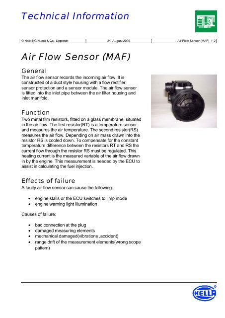
The air flow sensor records the in<strong>com</strong>ing air flow. It is<br />
constructed of a duct style housing with a flow rectifier,<br />
sensor protection and a sensor module. The air flow sensor<br />
is fitted into the inlet pipe between the air filter housing and<br />
inlet manifold.<br />
Function<br />
Two metal film resistors, fitted on a glass membrane, situated<br />
in the air flow. The first resistor(RT) is a temperature sensor<br />
and measures the air temperature. The second resistor(RS)<br />
measures the air flow. Depending on air mass drawn into the<br />
resistor RS is cooled down. To <strong>com</strong>pensate for the constant<br />
temperature difference between the resistors RT and RS the<br />
current flow through the resistor RS must be regulated. This<br />
heating current is the measured variable of the air flow drawn<br />
in by the engine. This measurement is needed by the ECU to<br />
assist in calculating the fuel injection.<br />
Effects of failure<br />
A faulty air flow sensor can cause the following:<br />
• engine stalls or the ECU switches to limp mode<br />
• engine warning light illumination<br />
Causes of failure:<br />
• bad connection at the plug<br />
• damaged measuring elements<br />
• mechanical damaged(vibrations ,accident)<br />
• range drift of the measurement elements(wrong scope<br />
pattern)
2<br />
<strong>Technical</strong> <strong>Information</strong><br />
© Hella KG Hueck & Co., Lippstadt 24. August 2000 <strong>Air</strong> <strong>Flow</strong> <strong>Sensor</strong> (<strong>MAF</strong>) 2-2<br />
Diagnostics<br />
For fault recognition consider the following system tests:<br />
1. Check electrical lead for correct fitting and contact<br />
2. Check air flow sensor for damage<br />
3. Check measurement elements for damage<br />
4. Measurement of the operation voltage, ignition on<br />
(wiring diagram needed for pin definition), measured<br />
value: 7.5…14 V<br />
5. Measurement of the output voltage, engine runs(wiring<br />
diagram needed for pin definition), measured value:<br />
0…. 5 V<br />
6. Check the wiring harness between the sensor plug<br />
and the removed ECU plug for short circuit to earth<br />
and continuity, measurement with an ohmmeter<br />
between sensor plug and vehicle ground, measured<br />
value: >30 Mohm, measurement between sensor and<br />
ECU plug, measured value: < 1 ohm<br />
7. Electronic check of the air flow sensor by the ECU. If<br />
there is a failure the ECU stores a fault/trouble code<br />
and the engine warning light is illuminated. The<br />
fault/trouble code can be read out with a code reader<br />
or a diagnostic test equipment.