IDH MAX® & ELECTROMECHANICAL LOCKS - Best Access Systems
IDH MAX® & ELECTROMECHANICAL LOCKS - Best Access Systems
IDH MAX® & ELECTROMECHANICAL LOCKS - Best Access Systems

You also want an ePaper? Increase the reach of your titles
YUMPU automatically turns print PDFs into web optimized ePapers that Google loves.
ELECTRIC SWITCH LOCK – INTRODUCTION<br />
ELECTRIC SWITCH LOCK – INTRODUCTION<br />
Stanley Security Solutions offers a line of electric switch locks available in various “on-off” and “momentary” keyed switch functions.<br />
Circuitry variations are available in single, double and triple pole with varied voltage and amperage ratings. Units may be keyed<br />
into any BEST system. The BEST interchangeable core offers versatility and adaptability for new and existing electrical controls,<br />
panels, machines, etc.<br />
Features<br />
• Double D lock cylinder prevents slipping and turning<br />
• Screw terminals on all switch locks (except the 1W7A1) provides ease of installation<br />
• All switches are UL recognized or listed<br />
Note on functionality: Switch lock keys can only be removed in the 12 o’clock position.<br />
How to select a switch lock<br />
1. Determine the electrical requirements for the device being controlled:<br />
A. Voltage (for example: 115 VAC or 24 VDC)<br />
B. Current or horsepower (for example: 6 amps or 1 /2 horsepower)<br />
C. Type of load<br />
• Resistive (for example, heater elements)<br />
• Inductive (for example, motors, large transformers)<br />
• Lamp (for example, incandescent lights)<br />
2. Determine the switch configuration (poles and throws) and key removal condition:<br />
A. Poles To determine the number of poles, find how many wires from the power source need to be switched on and off by the<br />
switch lock.<br />
B. Throws To determine the number of throws, find how many wires to the device the switch needs to control. For example, if a<br />
switch needs two different “on” conditions (low and high speed), two throws are needed. Or if the device is simply an “on-off”<br />
type (only one wire), you need one throw.<br />
Note: A switch throw may be left unwired and used as an “off” condition.<br />
C. Key removal To determine the key removal condition, ask the question, “When the key is removed, should the switch be<br />
“off”, or could the switch be either “on” or “off” ” Although the key can only be removed in the 12 o’clock position, the switch<br />
itself may be left in two or three positions. Check each switch lock for key removal switch positions.<br />
3. Use the information collected and find the switch lock that best meets the requirements. Refer to the following catalog<br />
pages for a description of each switch lock. If environmental conditions make it necessary that the switch lock be housed in an<br />
electrical box, see the Optional boxes (above) for the box that best suits the switch lock and your application.<br />
OPTIONAL BOXES<br />
OPTIONAL BOXES<br />
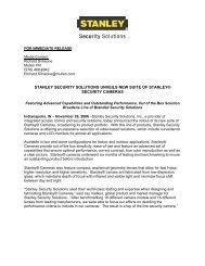
OC1<br />
Standard octagon<br />
center mount<br />
3 1 /2" x 3 1 /2" x 1 5 /8"<br />
OC2<br />
Deep octagon<br />
offset mount<br />
3 1 /2" x 3 1 /2" x 3 1 /4"<br />
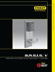
INT<br />
Interior box<br />
4" x 2 1 /8" x 1 7 /8"<br />
SWR<br />
Standard weather<br />
resistant box<br />
4 5 /8" x 2 7 /8" x 2 1 /4"<br />
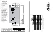
DWR<br />
Deep weather<br />
resistant box<br />
4 5 /8" x 2 7 /8" x 3"<br />
HOW TOORDER<br />
HOW TO ORDER – 1W ELECTRIC SWITCH LOCK<br />
1W 7 B1 626<br />
Series<br />
Function Finishes<br />
1W<br />
Core<br />
Housing<br />
7– 7 pin housing<br />
accepts all<br />
<strong>Best</strong> cores<br />
see pages<br />
15–19<br />
605 606<br />
611 612<br />
613 619<br />
622 625<br />
626 690<br />
SWR<br />
Box<br />
see above<br />
14<br />
<strong>IDH</strong> MAX ® & ELECTROM


![B.A.S.I.S. G Service Manual [T63300] - Best Access Systems](https://img.yumpu.com/48375082/1/190x245/basis-g-service-manual-t63300-best-access-systems.jpg?quality=85)