Bosch - Alarmes Tucano
Bosch - Alarmes Tucano
Bosch - Alarmes Tucano

You also want an ePaper? Increase the reach of your titles
YUMPU automatically turns print PDFs into web optimized ePapers that Google loves.
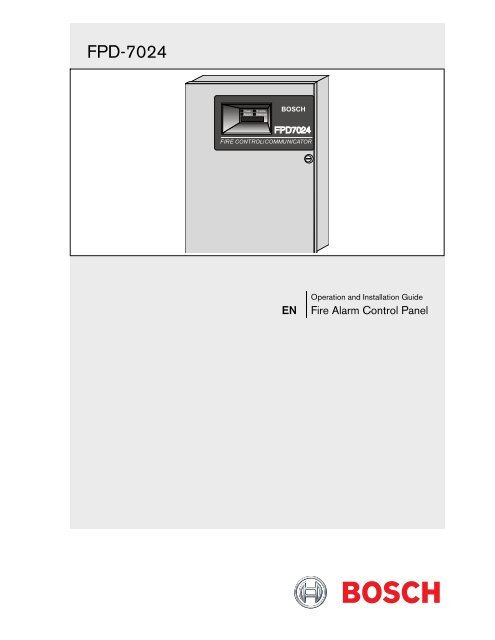
FPD-7024<br />
Power<br />
Alarm<br />
Trouble<br />
Silenced<br />
BOSCH<br />
FIRE CONTROL/COMMUNICATOR<br />
EN<br />
Operation and Installation Guide<br />
Fire Alarm Control Panel
FPD-7024 | Operation and Installation Guide | FCC Compliance Notice<br />
FCC Compliance Notice<br />
This equipment was tested and found to comply<br />
with the limits for a Class A digital device, pursuant<br />
to Part 15 of the FCC Rules. These limits are<br />
designed to provide reasonable protection against<br />
harmful interference in a residential installation. This<br />
equipment generates, uses, and can radiate radio<br />
frequency energy, and if not installed and used in<br />
accordance with the instructions, might cause<br />
harmful interference to radio communications.<br />
There is no guarantee that interference will not<br />
occur in a particular installation. If this equipment<br />
does cause harmful interference to radio or<br />
television reception, that can be determined by<br />
turning the equipment off and on, the user is<br />
encouraged to try to correct the interference by one<br />
or more of the following measures:<br />
Re-orient or relocate the receiving antenna.<br />
Increase the separation between the equipment and<br />
the receiver.<br />
Connect the equipment into an outlet on a circuit<br />
different from that to which the receiver is<br />
connected.<br />
Consult the dealer or an experienced radio or TV<br />
technician for help.<br />
FCC Phone Connection to Users<br />
This control panel complies with Part 68 of the FCC<br />
rules.<br />
On the inside of the enclosure is a label that<br />
contains, among other information, the ringer<br />
equivalence number (REN) for this equipment. You<br />
must, upon request, provide this information to your<br />
local telephone company.<br />
The REN is useful to determine the quantity of<br />
devices that can be connected to your telephone line<br />
and still have all of those devices ring when your<br />
telephone number is called. In most, but not all<br />
areas, the sum of the RENs of all devices connected<br />
to one line should not exceed five. To ascertain the<br />
number of devices that you can connect to your line,<br />
contact your local telephone company to determine<br />
the maximum REN for your local calling area.<br />
This equipment can not be used on coin service<br />
provided by the telephone company. Do not<br />
connect this control panel to party lines. If this<br />
equipment causes harm to the telephone network,<br />
the telephone company might discontinue your<br />
service temporarily. If possible, they will notify you<br />
in advance. But if advance notice isn’t practical, you<br />
will be notified as soon as possible.<br />
You will be informed of your right to file a<br />
complaint with the FCC. The telephone company<br />
might make changes in its facilities, equipment,<br />
operations, or procedures that could affect the<br />
proper functioning of your equipment. If they do,<br />
you will be notified in advance to give you an<br />
opportunity to maintain uninterrupted telephone<br />
service.<br />
If you experience trouble with this equipment,<br />
contact the manufacturer for information on<br />
obtaining service or repairs.<br />
The telephone company might ask that you<br />
disconnect this equipment from the network until<br />
the problem is corrected or until you are sure that<br />
the equipment is not malfunctioning. The<br />
manufacturer, not the user, must make the repairs to<br />
this equipment.<br />
To guard against accidental disconnection, there is<br />
ample room to mount the telco jack inside of the<br />
control panel cabinet.<br />
The operation of this control panel might also be<br />
affected if events such as accidents or acts of God<br />
cause an interruption in telephone service.<br />
Industry Canada Notice<br />
The Industry Canada label identifies certified<br />
equipment. This certification means that the<br />
equipment meets certain telecommunications<br />
network protective, operational, and safety<br />
requirements. Industry Canada does not guarantee<br />
the equipment will operate to the user’s satisfaction.<br />
Before installing this equipment, users should ensure<br />
that it is permissible to be connected to the facilities<br />
of the local telecommunications company. The<br />
equipment must also be installed using an<br />
acceptable method of connection. The customer<br />
should be aware that compliance with the above<br />
conditions might not prevent degradation of service<br />
in some situations.<br />
Repairs to certified equipment should be made by<br />
an authorized Canadian maintenance facility<br />
designated by the supplier. Any repairs or<br />
alterations made by the user to this equipment, or<br />
equipment malfunctions, might give the<br />
telecommunications company cause to request the<br />
user to disconnect the equipment.<br />
Users should ensure for their own protection that<br />
the electrical ground connections of the power<br />
utility, telephone lines, and internal metallic water<br />
pipe system, if present, are connected together.<br />
Users should not attempt to make such connections<br />
2<br />
<strong>Bosch</strong> Security Systems, Inc. | 9/08 | F01U008458-01
.<br />
themselves, but should contact the appropriate<br />
electric inspection authority, or electrician.<br />
FPD-7024 | Operation and Installation Guide | Trademarks<br />
Trademarks<br />
Microsoft ® , Windows ® , Windows NT ® are either<br />
registered trademarks or trademarks of Microsoft<br />
Corporation in the United States and/or other<br />
countries.<br />
CYCOLOY ® is a registered trademark of General<br />
Electric Company.<br />
POLYLAC ® is a registered trademark of CHI MEI<br />
Industrial Corporation, LTD.<br />
Chamber Check ® is a registered trademark of <strong>Bosch</strong><br />
Security Systems, Inc. in the United States.<br />
CleanMe is a trademark of GE Interlogix, Inc. in<br />
the United States and/or other countries.<br />
<strong>Bosch</strong> Security Systems, Inc. | 9/08 | F01U008458-01 3
FPD-7024 | Operation and Installation Guide | Contents<br />
Contents<br />
1.0 Overview...........................................................7<br />
1.1 System Overview ...............................................7<br />
1.2 Components........................................................8<br />
1.2.1 On-board Conventional Points.........................8<br />
1.2.2 Off-board Addressable Points (with D7039<br />
Multiplex Expansion Module)..........................8<br />
1.2.3 Enclosure Housing.............................................8<br />
1.2.4 Remote LCD Keypads ......................................8<br />
1.2.5 Remote LED Annunciators...............................8<br />
1.2.6 D7032 with the D7030X Use............................8<br />
1.2.7 Communicator....................................................9<br />
1.2.8 Users..................................................................10<br />
1.2.9 Lightning Protection ........................................10<br />
1.2.10 Backup Battery Calculation.............................11<br />
1.2.11 Standby Existing Load.....................................12<br />
1.2.12 Compatible Devices.........................................14<br />
1.3 Parts List............................................................16<br />
1.4 Installing the Enclosure ...................................16<br />
1.5 Installing the FPD-7024...................................16<br />
1.6 Installing Optional Equipment .......................17<br />
2.0 Control Panel Terminal Connections .......18<br />
2.1 Power Supply Connections.............................19<br />
2.2 Option Bus Wiring Requirements..................19<br />
3.0 System Operation ..........................................22<br />
3.1 Modes of Operation.........................................22<br />
3.1.1 Alarm.................................................................22<br />
3.1.2 Supervisory .......................................................22<br />
3.1.3 Trouble..............................................................22<br />
3.1.4 Acknowledge ....................................................22<br />
3.1.5 Fire Silence/Reset ............................................22<br />
3.1.6 Off-Normal Displays........................................22<br />
3.1.7 Normal ..............................................................22<br />
3.2 Basic System Use..............................................22<br />
3.2.1 Function Keys...................................................22<br />
3.2.2 Selecting Menu Items ......................................22<br />
3.2.3 After a Main Menu Item is Selected ..............23<br />
3.2.4 Returning to an Earlier Screen .......................23<br />
3.2.5 Entering Data....................................................23<br />
3.2.6 Drill....................................................................23<br />
3.2.7 Disable...............................................................23<br />
3.2.8 History...............................................................23<br />
3.3 Keypads.............................................................25<br />
3.3.1 Built-in Keypad ................................................25<br />
3.3.2 FMR-7033 Keypad...........................................26<br />
3.4 Testing ...............................................................26<br />
3.4.1 Walk Test ..........................................................26<br />
3.4.2 Communicator Test .........................................26<br />
3.4.3 Call for Remote Programming .......................27<br />
3.4.4 Test Battery/NAC Circuits..............................27<br />
3.4.5 Answer for Remote Programming .................27<br />
3.4.6 Manually Activate Outputs .............................27<br />
3.4.7 Read Zone Input Levels ..................................27<br />
3.4.8 Addressable Point Test (MUX Test) ..............27<br />
3.4.9 Sensitivity Test..................................................28<br />
3.5 Point/Zone Mapping........................................28<br />
3.6 Personal Identification Numbers ....................30<br />
3.7 Communicator Operation...............................31<br />
4.0 Programming ..................................................31<br />
4.1 Programming Features.....................................32<br />
4.2 Point Programming ..........................................33<br />
4.3 Alpha Programming.........................................34<br />
4.4 Format Programming.......................................35<br />
4.4.1 4/2......................................................................35<br />
4.4.2 BFSK..................................................................35<br />
4.4.3 SIA.....................................................................35<br />
4.4.4 Contact ID ........................................................35<br />
4.4.5 3/1......................................................................35<br />
4.4.6 Modem IIIa 2 ......................................................35<br />
4.5 Program Menu Tree ........................................36<br />
4.6 Shortcuts............................................................38<br />
4.7 Remote Programming......................................39<br />
5.0 Control Panel Programming .......................40<br />
5.1 PROG TIME ....................................................40<br />
5.1.1 Program Time...................................................40<br />
5.1.2 Automatic Test .................................................40<br />
5.1.3 Daylight Saving Time ......................................41<br />
5.2 SECURITY.......................................................41<br />
5.2.1 Personal Identification Numbers (PIN)..........41<br />
5.2.2 Authority ...........................................................42<br />
5.3 PROG SYSTEM ..............................................43<br />
5.3.1 Program Timers................................................43<br />
5.3.2 AC Line Synch .................................................45<br />
5.3.3 Option Bus........................................................45<br />
5.3.4 PIN REQUIRED .............................................46<br />
5.3.5 Remote Programming......................................47<br />
5.4 PROG INPUTS................................................47<br />
5.4.1 Point Number ...................................................47<br />
5.4.2 Point Function ..................................................50<br />
4<br />
<strong>Bosch</strong> Security Systems, Inc. | 9/08 | F01U008458-01
.<br />
5.4.3 Point Copy........................................................52<br />
5.5 PROG OUTPUTS ...........................................53<br />
5.5.1 Programming NACs ........................................53<br />
5.5.2 Programming Relays .......................................55<br />
5.6 PROG ACCOUNTS .......................................58<br />
5.6.1 Phone Numbers/IP Addresses........................58<br />
5.6.2 Phone Control ..................................................64<br />
5.6.3 Report Steering.................................................65<br />
5.6.4 Ring Count .......................................................66<br />
5.6.5 Communication Tries......................................66<br />
5.6.6 Machine Bypass................................................66<br />
5.6.7 ALT. Comm .....................................................66<br />
5.7 PROG FORMATS ..........................................67<br />
5.7.1 4/2 Zone Report...............................................67<br />
5.7.2 4/2 Report Codes.............................................68<br />
5.7.3 BFSK Report Codes.........................................69<br />
5.8 HISTORY DEFAULTS ..................................70<br />
5.8.1 Clear History ....................................................70<br />
5.8.2 Default EE.........................................................70<br />
5.8.3 Alternate 4/2 Codes.........................................71<br />
5.9 Program MUX..................................................71<br />
5.9.1 MUX Edit .........................................................71<br />
5.9.2 MUX Program..................................................72<br />
5.9.3 MUX Bus Type ................................................73<br />
5.9.4 Auto Program ...................................................74<br />
5.9.5 Removing MUX Devices................................77<br />
6.0 Installation Guide for UL Listed Systems.79<br />
6.1 FPD-7024 UL Listings .....................................79<br />
6.2 Installation Considerations..............................79<br />
6.3 Programming the FPD-7024 ...........................79<br />
6.3.1 Commercial Fire Alarm (Central Station<br />
[DACT] and Local) ..........................................79<br />
6.3.2 UL Listed Accessory Devices .........................79<br />
7.0 Fire Safety........................................................83<br />
7.1 Smoke Detector Layout...................................83<br />
7.1.1 General Considerations ...................................83<br />
7.1.2 Installing Family Residences...........................83<br />
7.2 Having and Practicing an Escape Plan ..........84<br />
Appendix A: Abbreviations on Control Panel<br />
Display .............................................................85<br />
Appendix B: Control Panel Display Descriptions 86<br />
Appendix C: Reporting Summary for Fire<br />
Communicator................................................87<br />
Appendix D: Programming Defaults List...............94<br />
Appendix E: Phone Monitor Troubleshooting......98<br />
Specifications ................................................................99<br />
FPD-7024 | Operation and Installation Guide | 1.0<br />
Index 100<br />
Overview<br />
<strong>Bosch</strong> Security Systems, Inc. | 9/08 | F01U008458-01 5
FPD-7024 | Operation and Installation Guide | Contents<br />
Figures<br />
Figure 1: FPD-7024 Control Board ...........................7<br />
Figure 2: Supplemental Reporting...........................10<br />
Figure 3: Enclosure Installation ...............................16<br />
Figure 4: Standoff and Support Post Installation ...17<br />
Figure 5: FPD-7024 Control Panel Terminal<br />
Connections...............................................18<br />
Figure 6: Connecting the Transformer to the<br />
FPD-7024 Circuit Board...........................19<br />
Figure 7: Option Bus Cable Length vs Existing<br />
Draw...........................................................21<br />
Figure 8: Built in Keypad .........................................25<br />
Figure 9: page width figure.......................................26<br />
Figure 10: Mapping, Inputs, Zones, and Outputs....29<br />
Figure 11: Essential Keys for Alpha Programming..35<br />
Figure 12: Example of a Programming Shortcut .....38<br />
Figure 13: D7039 Mounting Location.......................74<br />
Figure 14: Wiring the D132B-Smoke Power<br />
Reversing Module.....................................81<br />
Figure 15: Wiring the D185 .......................................82<br />
Figure 16: Smoke Detector locations in Residential<br />
Setting.........................................................83<br />
Table 19: PIN Authority Levels................................42<br />
Table 20: Pre-Assigned Zone Quick Reference ......54<br />
Table 21: Pre-Assigned Zone Quick Reference ......56<br />
Table 22: Pre-Assigned Zone Quick Reference ......57<br />
Table 23: Phone Number Control Characters ........59<br />
Table 24: Phone Number Assistance Keys..............59<br />
Table 25: IP Address Digit or Bit Location .............60<br />
Table 26: Phone Reporting .......................................61<br />
Table 27: Auto Programming Error Messages........76<br />
Table 28: Abbreviations on Control Panel Display85<br />
Table 29: Control Panel Display Descriptions........86<br />
Table 30: Reporting Summary for Fire<br />
Communicator...........................................87<br />
Table 31: Modem IIIa 2 reporting .............................89<br />
Table 32: History Log................................................92<br />
Table 33: Specifications. ............................................99<br />
Tables<br />
Table 1:<br />
Table 2:<br />
Two-Wire Circuits.......................................8<br />
LED Assignments for LED<br />
Annunciators 4 and 8 .................................9<br />
Table 3: LED Display for Zone 49 to 64.................9<br />
Table 4: Standby Battery Capacity Calculations ..11<br />
Table 5: Required Battery Size Calculation ..........12<br />
Table 6: Standby Load Battery Size (Ah) ..............12<br />
Table 7: Alarm Load Battery Size (Ah) .................13<br />
Table 8: Compatible Devices for the D7042,<br />
D7052 and D7053 Modules.....................14<br />
Table 9: Address Restrictions for the D7042,<br />
D7052, and D7053....................................15<br />
Table 10: Option Bus Wiring Guidelines ................20<br />
Table 11: Off-Normal Displays.................................22<br />
Table 12: History Event Abbreviations ...................24<br />
Table 13: Pre-Assigned Zones...................................29<br />
Table 14: PIN Authority Levels................................30<br />
Table 15: Programming Features for UL864...........32<br />
Table 16: Point Function Characteristics.................33<br />
Table 17: Mapping Input Points to Functions.........33<br />
Table 18: Programming the Points Using the<br />
Alphanumeric............................................34<br />
6<br />
<strong>Bosch</strong> Security Systems, Inc. | 9/08 | F01U008458-01
.<br />
1.0 Overview<br />
1.1 System Overview<br />
This guide applies to control panels<br />
equipped with version V1.00 or later<br />
software.<br />
The FPD-7024 Fire Alarm Control Panel is a fully<br />
integrated hard-wire fire alarm system. It can<br />
support four input points (expandable to 255 using<br />
D7039 Multiplex Expansion Module and the FPC-<br />
7034 Four-Point Expander) and 16 individual users<br />
(expandable to 100 with the D7039). The control<br />
panel has a built-in LCD keypad. Up to four<br />
additional keypads can be used to provide user<br />
interface with the system and programming access<br />
for the installer. The FPD-7024 also includes the<br />
following features:<br />
• Built-in dual-line communicator<br />
FPD-7024 | Operation and Installation Guide | 1.0<br />
• Menu driven keypad programming<br />
• Freely programmable<br />
alphanumeric/alphabetical display<br />
• 99 event history buffer<br />
• 16 user codes<br />
Overview<br />
• UL Listed, CSFM, MEA Approved<br />
When the D7039 Multiplex Expansion Module is<br />
installed, these additional features are available:<br />
• 247 additional addressable input points<br />
(255 total points)<br />
• 499 Non-volatile event history buffer<br />
• 100 user codes<br />
Refer to Figure 1 for the location of the major items<br />
on the FPD-7024 Control Board.<br />
Figure 1:<br />
FPD-7024 Control Board<br />
R2<br />
11<br />
10<br />
9<br />
N<br />
A<br />
C<br />
1<br />
N<br />
A<br />
C<br />
2<br />
A+<br />
B+<br />
B-<br />
A-<br />
A+<br />
B+<br />
B-<br />
A-<br />
AUX-<br />
AUX+<br />
BAT-<br />
24V<br />
BAT+<br />
Power<br />
Alarm<br />
Supervisory<br />
Trouble<br />
Silenced<br />
Gnd Flt<br />
HR2<br />
HT2<br />
T2<br />
R1<br />
RH1<br />
TH1<br />
T1<br />
NC 3<br />
COM3<br />
NO 3<br />
NC 2<br />
COM2<br />
NO2<br />
NC 1<br />
COM1<br />
NO 1<br />
SMK+<br />
SMK-<br />
1<br />
2<br />
3<br />
4A+<br />
4B+<br />
4B-<br />
4A-<br />
3A+<br />
3B+<br />
8<br />
1 2 3<br />
4 5 6<br />
7 8 9<br />
0 #<br />
*Back<br />
Prog<br />
Enter<br />
Drill<br />
Disable<br />
Test<br />
History<br />
Acknowledge<br />
Silence<br />
Reset<br />
3B-<br />
3A-<br />
2A+<br />
2B+<br />
2B-<br />
2A-<br />
1A+<br />
1B+<br />
1B-<br />
1A-<br />
4<br />
R B G Y OPTION BUS<br />
1. Telco Terminal Strip<br />
2 - Relay Terminal Strip<br />
3 - Smoke Power Terminal Strip<br />
4 - Zone Input Terminal Strip<br />
5 - Option Bus Terminal Strip<br />
6 - FPC-7034 Point Expander Connector Pins<br />
7 6 5<br />
7 - Keypad<br />
8 - D7039 MUX Expansion Module Connector Pins<br />
9 - LCD Display<br />
10 - NAC Terminal Strip<br />
11. Auxiliary Power Terminal Strip<br />
<strong>Bosch</strong> Security Systems, Inc. | 9/08 | F01U008458-01 7
FPD-7024 | Operation and Installation Guide | 1.0<br />
Overview<br />
1.2 Components<br />
1.2.1 On-board Conventional Points<br />
All on-board points and points implemented with<br />
the FPC-7034 work with two- or four-wire detectors.<br />
The system has an optional alarm verification<br />
feature.<br />
Table 1:<br />
Two-Wire Circuits<br />
Number of two-wire circuits<br />
Type of Circuit<br />
EOL Resistor<br />
Supervisory Existing<br />
Required Existing for Alarm<br />
Maximum Short Circuit<br />
Existing<br />
Maximum Line Resistance<br />
Circuit Voltage Range<br />
Maximum Detectors per<br />
Point<br />
Total Detector Standby<br />
Existing<br />
Response Time*<br />
Dirty Detector Monitoring<br />
* Refer to Section 6.4 on page 82.<br />
Four circuits, expandable to<br />
eight using an FPC-7034<br />
Expander<br />
Class B, Style 4 and Class<br />
A, Style 6 as needed)<br />
2.21 kΩ (P/N: 25899 or<br />
F01U034504),<br />
UL listed<br />
8 to 20 mA<br />
25 mA<br />
45 mA<br />
150Ω<br />
20.4 to 28.2 VDC<br />
20 detectors (two-wire)<br />
3 mA maximum<br />
Either fast (500 ms) or<br />
programmable (from 1 to 89<br />
seconds)<br />
Implements <strong>Bosch</strong> Security<br />
Systems, Inc. Chamber<br />
Check ® and GE Interlogix,<br />
Inc. CleanMe protocol to<br />
monitor conventional loops<br />
for dirty detectors.<br />
All on-board points, and points activated with the<br />
FPC-7034 Four Point Expander, are continuously<br />
monitored for detectors signaling a dirty condition<br />
using the <strong>Bosch</strong> Security Systems, Inc. Chamber<br />
Check and GE Interlogix, Inc. CleanMe protocols.<br />
To prevent nuisance reports, a two-minute delay<br />
occurs before a dirty detector is annunciated. A sixminute<br />
delay occurs after the detector restores from<br />
the dirty condition before the control panel restores<br />
the condition.<br />
1.2.2 Off-board Addressable Points (with<br />
D7039 Multiplex Expansion Module)<br />
The D7039 Multiplex Expansion Module adds:<br />
• Two Class B, Style 4 or one Class A, Style 6<br />
Signaling Line Circuits (SLCs)<br />
• Each point is individually supervised for proper<br />
connection to the common bus (when over ten<br />
points are troubled, up to ten troubles are<br />
shown per bus and the balance of the troubles is<br />
indicated by a common bus failure message).<br />
• Response time can be set to fast, or<br />
programmed from 1 to 89 seconds.<br />
• Input points on the SLCs are implemented with<br />
a D7042 Eight Input Remote Module.<br />
1.2.3 Enclosure Housing<br />
The standard enclosure is 18 ga., cold-rolled steel,<br />
and measures 20.75 in. x 15 in. x 4.25 in. (52.7 cm x<br />
38.1 cm x 10.8 cm). A keyed lock is included, and<br />
the LEDs and LCD display are visible through the<br />
door.<br />
1.2.4 Remote LCD Keypads<br />
Maximum number of keypads: Four FMR-7033<br />
LCD Fire Keypads.<br />
Wiring Requirements: Refer to Section 2.2 Option Bus<br />
Wiring Requirements on page 19.<br />
1.2.5 Remote LED Annunciators<br />
Maximum number of annunciators: Eight D7030<br />
eight-zone LED Annunciators.<br />
Wiring Requirements: Refer to Section 2.2 Option Bus<br />
Wiring Requirements on page 19.<br />
1.2.6 D7032 with the D7030X Use<br />
When a D7032 Eight-Zone LED Annunciator<br />
Expander is connected to the D7030X, eight<br />
additional LED zones appear. This allows the<br />
D7030X/D7032 combination to show 16 LED<br />
zones. Up to eight D7030X/D7032 combinations<br />
can be connected to the FPD-7024 Fire Alarm<br />
Control Panel. Refer to Table 2 on page 9 for zones<br />
shown by each D7030X/D7032 combination.<br />
Each D7030X processes 16 zones of<br />
information. If no D7032 is attached, only<br />
the lower eight zones are shown.<br />
The column labeled Shown on D7030X” In<br />
Table 2 on page 9 applies regardless if an<br />
attachment of a D7032 to any D7030X is<br />
made.<br />
8<br />
<strong>Bosch</strong> Security Systems, Inc. | 9/08 | F01U008458-01
.<br />
FPD-7024 | Operation and Installation Guide | 1.0<br />
Overview<br />
Table 2: LED Assignments for LED Annunciators 4 and 8<br />
D7030X<br />
Zones<br />
Covered<br />
Shown on<br />
7030X<br />
Shown on<br />
D7032 (if<br />
attached)<br />
COMMENTS<br />
1 1 to 16 1 to 8 9 to 16 Combination with lowest option bus address (such as Address 1)<br />
2 17 to 32 17 to 24 25 to 32 Combination with second lowest option bus address (such as<br />
Address 2)<br />
3 33 to 48 33 to 40 41 to 48 Combination with third lowest option bus address (such as<br />
Address 3)<br />
4 49 to 64 49 to 56 57 to 64 Combination with fourth lowest option bus address (such as<br />
Address 4)<br />
5 1 to 16 1 to 8 9 to 16 Fifth combination repeats first combination<br />
6 17 to 32 17 to 24 25 to 32 Sixth combination repeats second combination<br />
7 33 to 48 33 to 40 41 to 48 Seventh combination repeats third combination<br />
8 49 to 64 49 to 56 57 to 64 Eighth combination repeats forth combination<br />
Refer to Table 3 for the LED display for Zones 49 to 64.<br />
Table 3: LED Display for Zone 49 to 64<br />
LED Zone Description<br />
1 49 User defined<br />
2 50 User defined<br />
3 (reserved)<br />
4 52 General fire alarm monitor waterflow (non-silencable)<br />
5 53 General fire alarm monitor (silencable)<br />
6 (reserved)<br />
7 55 General Supervisory (silencable)<br />
8 56 General Waterflow (silencable)<br />
9 (reserved)<br />
10 58 General supervisory alarm (non-silencable)<br />
11 (reserved)<br />
12 (reserved)<br />
13 61 General waterflow alarm (non-silencable)<br />
14 (reserved)<br />
15 63 General alarm monitor waterflow (non-silencable)<br />
16 (reserved)<br />
1.2.7 Communicator<br />
The communicator can report to two phone<br />
numbers or IP addresses with full single, double,<br />
and back-up reporting. Communicates in SIA,<br />
Modem IIIa2, Contact ID, BFSK, and 3/1 and 4/2<br />
Tone burst formats.<br />
The communicator must be enabled and<br />
configured to operate. The communicator<br />
and phone line monitors are disabled in<br />
the default factory configuration.<br />
<strong>Bosch</strong> Security Systems, Inc. | 9/08 | F01U008458-01 9
FPD-7024 | Operation and Installation Guide | 1.0<br />
Phone Line and Phone Number/IP Selection: To<br />
ensure the delivery of critical reports, the fire panel<br />
has two phone lines and two phone numbers or IP<br />
addresses that can be used for reporting. Reports<br />
can be directed to one or both of two phone<br />
numbers or IP addresses using the Report Steering<br />
feature (refer to Section 5.6.3 Report Steering on page<br />
65) in the control panel programming. Note that<br />
Account Number 1 is used with Phone Number/IP<br />
1, and Account Number 2 is used with Phone<br />
Number/IP 2. Except for test reports, the control<br />
panel automatically selects the phone line or IP<br />
address to use. If the report is not successful after<br />
two attempts on Line 1, the control panel<br />
automatically switches and uses Phone Line 2. One<br />
exception is when test reports (manual or automatic)<br />
are sent. Test reports are sent every 4 hours to 28<br />
days. Each time a Test report is sent, the control<br />
panel alternates phone lines. This happens even if<br />
the monitor says the line is bad. If the user sends<br />
two manual test reports both phone lines can be<br />
tested. The first report uses one line and the second<br />
uses the other line. During normal operation, the<br />
automatic test uses a different line each day.<br />
Because the control panel automatically selects<br />
which line to use, both phone lines must use the<br />
same dialing sequences for sending reports. For<br />
example, a line that requires a 9 to be dialed for an<br />
outside line cannot be paired with a line that does<br />
not require a 9.<br />
PBX lines and ground start phone lines do<br />
not comply with NFPA requirements for<br />
digital communication.<br />
While the control panel is idle, the FACP monitors<br />
the primary and alternate telephone lines by<br />
monitoring the line for trouble. The FACP monitors<br />
each line every 12 seconds. When a trouble still<br />
exists after three samples (36 seconds), the FACP<br />
sends a trouble report and activates the yellow<br />
trouble LED and trouble relay.<br />
If the central station receives the automatic<br />
test report only every other day, this<br />
indicates that one phone line at the<br />
protected premises is inoperative. Correct<br />
this condition immediately, because other<br />
critical reports can be delayed when the<br />
communicator is trying to send the test<br />
signal through the inoperative phone line<br />
(once each 48 hours).<br />
Overview<br />
Supplemental Reporting: While two independent<br />
phone lines are required for UL864 Central Station<br />
service, the FACP can be configured with one<br />
phone line if the control panel is used only for<br />
supplemental reporting on a local, remote station or<br />
auxiliary system.<br />
Connect a jumper from T1 to T2 and R1 to R2 if<br />
the control panel is installed with only one phone<br />
line. Refer to Figure 2.<br />
Figure 2:<br />
1<br />
2<br />
Control panel reports can be delayed if the<br />
dialer outputs are not connected together<br />
on an installation where the control panel<br />
has only one phone line<br />
Supplemental Reporting<br />
R2<br />
HR2<br />
HT2<br />
T2<br />
R1<br />
RH1<br />
TH 1<br />
1 - Jumper from R1 to R2<br />
2 - Jumper from T1 to T2<br />
3 - House phone<br />
4 - Telco Line<br />
T1<br />
1.2.8 Users<br />
The system allows up to 16 individual users, or up<br />
to 100 users when the D7039 is installed. A personal<br />
identification number (PIN) the four-digit code<br />
entered at the keypads, and an authority level to<br />
determine which functions can be performed (refer<br />
to Section 5.2.1 Personal Identification Numbers on<br />
page 41) can be assigned to each user.<br />
1.2.9 Lightning Protection<br />
This system is intended for installation<br />
entirely within one building.<br />
Metal-oxide varistors (MOV) and spark gaps<br />
provide protection from lightning surges and static<br />
discharges.<br />
3<br />
4<br />
10<br />
<strong>Bosch</strong> Security Systems, Inc. | 9/08 | F01U008458-01
FPD-7024 | Operation and Installation Guide | 1.0<br />
Overview<br />
.<br />
1.2.10 Backup Battery Calculation<br />
Use Table 4 to calculate the standby battery capacity required by NFPA when using the FPD-7024.<br />
Table 4:<br />
Standby Battery Capacity Calculations<br />
Device Quantity Standby<br />
Existing/Device<br />
Total<br />
Standby<br />
Alarm<br />
Existing/Device<br />
Total Alarm<br />
FPD-7024 Control panel 1 200 mA 200 mA 380 mA 380 mA<br />
FPC-7034 Four-Point Expander 44 mA 156 mA<br />
D7035/B Octal Relay 1 8 Ma + 30 mA 2 8 Ma + 30 mA 2<br />
D7048/B Octal Driver Module 10 mA 10 mA<br />
FMR-7036 Annunciator Keypad 80 mA 100 mA<br />
D7030X Eight-Point LED Annunciator 1 27 mA 132 mA<br />
D7030X-S2 Eight-Point LED Annunciator 35 mA 175 mA<br />
D7030X-S8 Eight-Point LED Annunciator 35 mA 175 mA<br />
D7032 Eight-Point LED Annunciator<br />
1 mA 90 mA<br />
Expander<br />
FMR-7033 Keypad 1 80 mA 100 mA<br />
D7039 MUX Expansion Module 150 mA 150 mA<br />
D7042/B Addressable Eight Point Input 18 mA 18 mA<br />
D7050 MUX Photoelectric Smoke<br />
0.50 mA 0.56 mA<br />
Detector<br />
D7050TH MUX Photoelectric Smoke<br />
0.50 mA 0.56 mA<br />
Detector<br />
FMM-7045 Mux Pull Station 0.55 mA 0.55 mA<br />
D7044 Mux Single Input Fire 0.55 mA 0.55 mA<br />
D7044M Mux Mini Contact Module 0.55 mA 0.55 mA<br />
D7052 Mux Dual Input Fire 0.55 mA 0.55 mA<br />
D7053 Mux I/O Module Fire 0.70 mA 0.70 mA<br />
Smoke Detectors<br />
Bells, Horns, and so on<br />
Other Sensors<br />
Other<br />
Grand Total<br />
Standby Existing<br />
Grand Total<br />
Alarm Existing<br />
1<br />
The 24 VDC existing requirements for the D7030X, FMR-7033 and D7035 are shown at 75% of the 12 VDC level shown on<br />
the specification sheets for these models. The FPD-7024 regulates 24 VDC power from the battery to 12 VDC for these<br />
accessories.<br />
2<br />
Add 30 mA for each relay activated<br />
<strong>Bosch</strong> Security Systems, Inc. | 9/08 | F01U008458-01 11
FPD-7024 | Operation and Installation Guide | 1.0<br />
Overview<br />
The units shown in Table 5 are Amp hours (Ah), and the figures include a 20% derating factor.<br />
Table 5:<br />
Required Battery Size Calculation<br />
Grand Total Standby Existing (in amps)<br />
Total Hours of Standby Required (usually 24 or 60):<br />
Total Standby Capacity (multiply CS X HS)<br />
CS<br />
HS<br />
TS= CS X HS<br />
Grand Total Alarm Existing (in amps)<br />
Total Hours of Alarm Time Required (usually 0.083 or 0.25):<br />
Total Standby Capacity (multiply CA X HA)<br />
CA<br />
HA<br />
TA= CA X HA<br />
Total Capacity Required (add TA + TS):<br />
TC = TA + TS<br />
Required Capacity with 20% Derating (TC X 1.2) C = TC X 1.2<br />
The required battery size to support the system can be calculated using Table 6 and Table 7<br />
on page 13.<br />
1.2.11 Standby Existing Load<br />
Use Table 6 to estimate the size of the battery required to support the standby load, then use Table 7 on page 13 to<br />
estimate the size of the battery required to support the alarm load. Add the results together for the total battery<br />
size. Select the next larger standard battery for the system. If the results show a requirement for a battery over 40<br />
Ah, reduce the existing or add an external regulated fire protective signaling power supply.<br />
Table 6:<br />
Standby Load Battery Size (Ah)<br />
Standby Load Battery Size Chart<br />
Capacity Required for<br />
24 Hours<br />
Capacity Required for<br />
48 Hours<br />
Grand Total Standby Existing<br />
100 to 200 mA 5.8 11.5 14.4<br />
201 to 300 mA 8.6 17.3 21.6<br />
301 to 400 mA 11.5 23.0 28.8<br />
401 to 500 mA 14.4 28.8 36.0<br />
501 to 600 mA 17.3 34.6 X<br />
601 to 700 mA 20.2 X X<br />
701 to 800 mA 23.0 X X<br />
801 to 900 mA 25.9 X X<br />
901 to 1000 mA 28.8 X X<br />
1001 to 1100 mA 31.7 X X<br />
Capacity Required for<br />
60 Hours<br />
12<br />
<strong>Bosch</strong> Security Systems, Inc. | 9/08 | F01U008458-01
.<br />
Table 7:<br />
Alarm Load Battery Size (Ah)<br />
FPD-7024 | Operation and Installation Guide | 1.0<br />
Overview<br />
Alarm Load Battery Size Chart<br />
Grand Total Standby Existing<br />
Capacity<br />
Required for 5<br />
Minutes<br />
Capacity<br />
Required for 10<br />
Minutes<br />
Capacity<br />
Required for 15<br />
Minutes<br />
Capacity<br />
Required for 30<br />
Minutes<br />
250 to 500 mA 0.1 0.1 0.2 0.3 0.5<br />
501 to 999 mA 0.1 0.2 0.3 0.6 0.9<br />
1.0 to 1.5 A 0.2 0.3 0.5 0.9 1.4<br />
1.6 to 2.0 A 0.2 0.4 0.6 1.2 1.8<br />
2.1 to 2.5 A 0.3 0.5 0.8 1.5 2.3<br />
2.6 to 3.0 A 0.3 0.6 0.9 1.8 2.7<br />
3.1 to 3.5 A 0.4 0.7 1.1 2.1 3.2<br />
3.6 to 4.0 A 0.4 0.8 1.2 2.4 3.6<br />
Capacity<br />
Required for 45<br />
Minutes<br />
<strong>Bosch</strong> Security Systems, Inc. | 9/08 | F01U008458-01 13
FPD-7024 | Operation and Installation Guide | 1.0<br />
Overview<br />
1.2.12 Compatible Devices<br />
Table 8:<br />
Compatible Devices<br />
Device<br />
D7030 Eight Point LED<br />
Annunciator<br />
D7030X Eight Point LED<br />
Annunciator<br />
D7030X-S2 Eight Point<br />
LED Annunciator<br />
D7030X-S8 Eight Point<br />
LED Annunciator<br />
D7032 Eight Point LED<br />
Annunciator Expander<br />
FMR-7033 Alphanumeric<br />
LCD Keypad<br />
FPC-7034 Four Point<br />
Expander<br />
D7035/B Octal Relay<br />
Module<br />
FMR-7036 Fire<br />
Annunciator Keypad<br />
FPP-RNAC-8A-4C Remote<br />
NAC Power Supply<br />
D7039 Multiplex<br />
Expansion Module<br />
D7042/B Eight-Input<br />
Remote Module<br />
D7048/B Octal Driver<br />
Module<br />
FMM-7045 Mux Pull<br />
Station<br />
D7044 Mux Single Input<br />
Fire<br />
D7044M Mux Mini Contact<br />
Module<br />
Function<br />
Identifies the location of a fire alarm for up to eight zones allowed per system.<br />
Identifies the location of a fire alarm for up to eight zones allowed per system.<br />
An eight-zone LED annunciator, of which two zones are reserved for supervisory functions. It has<br />
Power and Trouble LEDs plus eight-zone LEDs that can be labeled individually.<br />
An eight-zone LED annunciator, of which all eight zones are reserved for supervisory functions. It<br />
has Power and Trouble LEDs plus eight-zone LEDs that can be labeled individually.<br />
Attaches to a D7030X and identifies the location of a fire alarm for eight additional zones.<br />
Connects up to four-keypads per system.<br />
Allows the FPD-7024 Control Panel to support four additional points. The FPC-7034 plugs into<br />
the control panel and provides four Class B, Style 4 loops that are identical in characteristics to<br />
the loops on the control panel. One FPC-7034 is allowed per system.<br />
Provides eight Form C relay outputs for addition to the system. The outputs are programmable<br />
and can be activated by system events. Each output operates independently of the other seven<br />
outputs for complete flexibility. The D7035 connects to the option bus; up to two are allowed<br />
per system. Refer to the D7035 Installation Guide (P/N: 37280) for required enclosure<br />
modification. The D7035B comes installed on a mounting skirt.<br />
Establishes the location of a fire alarm.<br />
Adds four NFPA 72 Class B, Style Y Notification Appliance Circuits through the option bus and<br />
is supervised by the control panel. The FPP-RNAC-8A-4C connects to the option bus of the<br />
FPD-7024 control panel and up to four are allowed per system.<br />
Provides either 2 two-wire (Class B, Style 4) multiplex buses or 1 four-wire (Class A, Style 6)<br />
multiplex bus. In Class A mode, up to 120 addressable points can be added. In Class B Mode,<br />
up to 247 addressable points can be added. The D7039 connects directly to the control panel.<br />
One is allowed per system.<br />
Provides eight Class B, Style 4 input points. Connect up to 15 modules to MUX Bus A, and 15<br />
on MUX Bus B. The D7042 is powered by 12 VDC supplied by the option bus power terminals,<br />
in addition to the two-wire data connection. The D7042 can not be used on a signal line circuit<br />
(SLC) configured for Class A, Style 6 operation.<br />
Provides eight open collector transistor outputs for addition to the FPD-7024 Fire Alarm Control<br />
panels. It connects to the control panels through the option bus.<br />
UL Listed fire alarm initiating device.<br />
Connects a contact device to the multiplex bus of the FPD-7024 with a supervised local loop.<br />
The D7044 draws operating power from the FPD-7024.<br />
Connects a contact device to the multiplex bus of the FPD-7024 with a supervised input loop.<br />
The D7044 draws operating power from the FPD-7024.<br />
14<br />
<strong>Bosch</strong> Security Systems, Inc. | 9/08 | F01U008458-01
.<br />
FPD-7024 | Operation and Installation Guide | 1.0<br />
Overview<br />
Table 8:<br />
Compatible Devices (continued)<br />
D7052 Mux Dual Input Fire<br />
D7053 Mux I&O Module<br />
Fire<br />
D7050/TH Mux Smoke<br />
Detector<br />
Connects to the multiplex bus of the FPD-7024 and provides two supervised input zones for<br />
connecting conventional normally-open inputs. The D7052 draws operating power from the<br />
FPD-7024.<br />
Connects to the multiplex bus of the FPD-7024 and implements a supervised local loop, and a<br />
Form C relay output. Up to 20 modules can be connected to each MUX bus. The D7053 draws<br />
operating power from the FPD-7024.<br />
The D7050/TH is a photo-electric smoke detector with a heat option. It connects to the<br />
multiplex bus of the FPD-7024. The D7050 draws operating power from the<br />
FPD-7024.<br />
Table 9:<br />
Address Restrictions for the D7042, D7052, and D7053<br />
Install D7042 modules only at addresses:<br />
9 17 25 33 41 49 57 65<br />
73 81 89 97 105 113 121 129<br />
137 145 153 161 169 177 185 193<br />
201 209 217 225 233 241<br />
Do not install D7052 and D7053 modules at these addresses<br />
16 24 32 40 48 56 64 72<br />
80 88 96 104 112 120 128 136<br />
144 152 160 168 176 184 192 200<br />
208 216 224 232 240 248 255<br />
<strong>Bosch</strong> Security Systems, Inc. | 9/08 | F01U008458-01 15
FPD-7024 | Operation and Installation Guide | 1.0<br />
Overview<br />
1.3 Parts List<br />
• One FPD-7024 Control/Communicator in staticresistant<br />
bag<br />
• One enclosure with transformer<br />
• One hardware pack<br />
• One enclosure lock, washer, and keys<br />
• Six end-of-line (EOL) resistors<br />
The hardware necessary for installing the control<br />
panel in the enclosure is located in the hardware<br />
pack.<br />
1.4 Installing the Enclosure<br />
1. Using the enclosure as a template, mark the top<br />
mounting holes on the mounting surface<br />
(Figure 3).<br />
2. Start the mounting screws (not supplied) for<br />
these two holes.<br />
3. Slide the enclosure onto these screws so that the<br />
screws rest on the thinner section of the holes.<br />
4. Tighten the screws.<br />
5. Install and tighten the remaining two screws in<br />
the bottom mounting holes.<br />
6. Knock out the desired wire entrances on the<br />
enclosure.<br />
Figure 3:<br />
7<br />
6<br />
5<br />
1<br />
Enclosure Installation<br />
1 - Control panel location<br />
2 - Mounting holes<br />
3 - Retainer holes for standoffs<br />
4 - Retainer holes for support posts<br />
5 - Transformer<br />
6 - Stud<br />
7 - Ground wire<br />
2<br />
2<br />
3<br />
4<br />
If using the knockouts located at the<br />
bottom of the enclosure install batteries in<br />
a separate enclosure.<br />
1.5 Installing the FPD-7024<br />
The control circuit board in the FPD-7024<br />
is static sensitive. Touch ground before<br />
handling the control board. This discharges<br />
any static electricity in your body. For<br />
example, run the ground wire to the<br />
enclosure before handling the control<br />
circuit board. Continue touching the<br />
enclosure while installing the control board.<br />
1. Insert the three support posts in the enclosure’s<br />
retainer holes. Refer to Figure 3 above and<br />
Figure 4 on page 17.<br />
16<br />
<strong>Bosch</strong> Security Systems, Inc. | 9/08 | F01U008458-01
.<br />
2. Press the 1/8 in. nylon standoffs<br />
(P/N: F01U034705) into the retainer holes.<br />
3. Slide the top of the control panel onto the<br />
retainer tabs (the slots under the top of the<br />
frame). When the control panel is in the retainer<br />
tabs, it rests on the posts.<br />
4. Secure the bottom of the circuit board by<br />
inserting and tightening the screws at the two<br />
bottom corners through the support posts and<br />
the retainer holes Figure 4.<br />
Connect the supplied ground wire between<br />
the door and the enclosure using the<br />
supplied nuts before the circuit board is<br />
installed.<br />
A second ground wire is provided for connecting<br />
the AC power ground. Both grounds connect to the<br />
stud in the enclosure to the left of the circuit board.<br />
Refer to Figure 3 on page 16.<br />
Figure 4:<br />
1<br />
2<br />
Standoff and Support Post Installation<br />
1 - 1/8 in. nylon standoff<br />
2 - Retainer holes<br />
3 - Support post assembly<br />
4 - Corner of circuit board<br />
5 - Support post<br />
6 - Retainer hole in enclosure<br />
1.6 Installing Optional Equipment<br />
Two expansion options connect directly to the<br />
control panel, and are automatically detected and<br />
supervised when the control panel is powered:<br />
• FPD-7034 Four Point Expander<br />
• D7039 Multiplex Expansion Module<br />
When the control panel is powered after installing<br />
one of these options, the control panel displays one<br />
of the following windows:<br />
4Z EXP DETECTED<br />
PRESS ENTER KEY<br />
4<br />
5<br />
6<br />
3<br />
=<br />
FPD-7024 | Operation and Installation Guide | 1.0<br />
MUX DETECTED<br />
PRESS ENTER KEY<br />
Overview<br />
Press the [#/Enter] key to confirm the installation of<br />
the device and automatically set it up for<br />
supervision.<br />
If the [#/Enter] key is not pressed during the powerup<br />
time-out period, the control panel resumes<br />
operation using the last confirmed status of the<br />
affected expander and displays an installation error<br />
condition.<br />
Expansion devices such as point expanders<br />
and multiplex expanders are disabled if they<br />
are removed from the control panel<br />
configuration after installation. You cannot<br />
disable supervision of these devices when<br />
they are installed.<br />
Refer to the installation instructions for these<br />
expanders for additional information.<br />
When the D7039 Multiplex Expansion<br />
Module is first installed, the system displays<br />
an EEPROM fault. Execute the default<br />
procedure to synchronize the EEPROM on<br />
the expansion module to the EEPROM in<br />
the control panel. Remove power to the<br />
control panel, then reapply power and reinstall<br />
option bus devices after the default<br />
procedure.<br />
Replacing a D7039 Multiplex Expansion<br />
Module causes the loss of programming of<br />
expansion points and PINs. Reprogram all<br />
multiplex point and PINs if you replace the<br />
D7039.<br />
When the D7039 is first installed, or anytime the<br />
control panel is powered with a D7039 that has no<br />
points programmed, the system automatically starts<br />
the multiplex auto-programming process:<br />
AUTO PROGRAM<br />
:YES(1)/NO(0)<br />
Pressing the [1] key starts auto-programming, and<br />
pressing [0/Prog] allows the control panel to<br />
continue normal startup. The menu automatically<br />
closes with NO selected if no key is pressed after<br />
several minutes. Refer to Section 5.9.4 Auto Program<br />
on page 74 for detailed instructions on the autoprogramming<br />
mode.<br />
<strong>Bosch</strong> Security Systems, Inc. | 9/08 | F01U008458-01 17
Alarm<br />
Silenced<br />
Supervisory<br />
Trouble<br />
TEST WEEKLY<br />
1 2 3<br />
4 5 6<br />
7 8 9<br />
0<br />
Back<br />
Prog<br />
Ente r<br />
History<br />
Silence<br />
ACK<br />
Reset<br />
Drill<br />
Test<br />
FPD-7024 | Operation and Installation Guide | 2.0<br />
Control Panel Terminal Connections<br />
2.0 Control Panel Terminal Connections<br />
Figure 5:<br />
FPD-7024 Control Panel Terminal Connections<br />
-<br />
Incorrect connections may result<br />
in damage to the unit and personal injury.<br />
Before servicing this equipment, remove all<br />
power including the transformer, battery<br />
and phone lines.<br />
Shared cable is not recommended for<br />
option bus, telephone or NAC wiring.<br />
Typical 2-wire<br />
smoke detector<br />
wiring (supervised)<br />
EOL<br />
Resistor<br />
Typical Fire Wiring<br />
CLASS A<br />
STYLE D<br />
CLASS B<br />
STYLE B<br />
Typical 4-wire smoke<br />
detector wiring.<br />
CLASS A<br />
STYLE D<br />
CLASS B<br />
STYLE B<br />
R2<br />
HR2<br />
HT2<br />
T2<br />
For connection to<br />
listed power limited<br />
Class 2 or Class 3<br />
sources only.<br />
switched<br />
unsupervised<br />
Phone Line 2<br />
(Supervised)<br />
unsupervised<br />
unsupervised<br />
unsupervised<br />
Contacts<br />
rated at<br />
5.0 A, 24 V<br />
Relay 3<br />
Relay 2<br />
Relay 1<br />
Smoke Power: 24 V, 1.0 A max. (filtered)<br />
Refer to Technogram P/N: F01U010790<br />
for compatible devices.<br />
Earth Ground<br />
Input Points 1-4:<br />
(supervised) Points are intended for<br />
connection of normally-open/<br />
normally-closed alarm contacts.<br />
They may also be used for compatible<br />
two-wire smoke detectors.<br />
All EOL resistors are 2.21 k Ω,<br />
P/N: 25899 <strong>Bosch</strong>,UL listed.<br />
Initiating devices are Class B, Style B<br />
or Class A , Style D.<br />
Two-Wire Compatibility Identifier “A”.<br />
NC 3<br />
COM3<br />
NO 3<br />
NC 2<br />
COM2<br />
NO2<br />
NC 1<br />
COM1<br />
NO 1<br />
SMK+<br />
SMK-<br />
4A+<br />
4B+<br />
4B-<br />
4A-<br />
3A+<br />
3B+<br />
3B-<br />
3A-<br />
2A+<br />
2B+<br />
2B-<br />
2A-<br />
1A+<br />
1B+<br />
1B-<br />
1A-<br />
Red<br />
Brown<br />
NC<br />
AC Power 2<br />
NC<br />
AC Power 1<br />
R1<br />
RH1<br />
TH1<br />
T1<br />
Phone Line 1<br />
(Supervised)<br />
BOSCH<br />
COM<br />
+12V DATA<br />
Black<br />
(-)<br />
DX4020<br />
Yellow<br />
(supervised) White<br />
Black<br />
All wiring except battery terminal and<br />
primary AC power is power-limited.<br />
Primary AC and battery wires must be<br />
separated from other wires by at least<br />
¼ in. (64 mm) and tied to prevent<br />
movement.<br />
unswitched<br />
unsupervised<br />
Aux. Power: 24 V, 1.0 A max.<br />
(unfiltered)<br />
(-)<br />
(+)<br />
Battery # 1 Battery # 2<br />
(+)<br />
Red<br />
CLASS B<br />
STYLE Y<br />
EOL<br />
(supervised)<br />
CLASS A<br />
STYLE Z<br />
* # Disable<br />
A+<br />
N<br />
B+ A<br />
C<br />
B-<br />
1<br />
A-<br />
A+<br />
N<br />
B+ A<br />
C<br />
B-<br />
2<br />
A-<br />
NAC 1+<br />
NAC 1-<br />
NAC 2+<br />
NAC 2-<br />
BAT -<br />
BAT +<br />
R B G Y OPTION BUS<br />
Supervised, Class B,<br />
Style 4, 500 mA , Max.<br />
NOTIFICATION APPLIANCE CIRCUIT:<br />
+24 V while in alarm; ground while in standby.<br />
Ground while in alarm; supervisory voltage while in standby.<br />
NOTIFICATION APPLIANCE CIRCUIT:<br />
+24 V while in alarm; ground while in standby.<br />
Ground while in alarm; supervisory voltage while in standby.<br />
BATTERIES:<br />
Requires two 12 V batteries, in series, for a combined voltage of<br />
24 V. Charge current = 1.1 A, max.<br />
Use only indicating devices as listed on Technogram P/N: F01U010791.<br />
Battery # 1 Battery # 2 Red<br />
Backup Batteries<br />
Black<br />
1A+<br />
1B+<br />
1B-<br />
1A-<br />
SMK+<br />
SMK-<br />
1A+<br />
1B+<br />
1B-<br />
1A-<br />
1A+<br />
1B+<br />
1B-<br />
1A-<br />
1A+<br />
1B+<br />
1B-<br />
1A-<br />
SMK+<br />
SMK-<br />
AUX-<br />
AUX+<br />
BAT-<br />
24V<br />
BAT+<br />
Do not short terminals - explosion and burn hazard.<br />
18<br />
<strong>Bosch</strong> Security Systems, Inc. | 9/08 | F01U008458-01
.<br />
FPD-7024 | Operation and Installation Guide | 2.0<br />
Control Panel Terminal Connections<br />
2.1 Power Supply Connections<br />
Use wire nuts to connect the primary side of the<br />
transformer (black and white wires) to the<br />
unswitched 120 V, 60 Hz or (yellow and white<br />
wires) to unswitched 240 V, 50 Hz circuit. Connect<br />
the earth ground to the threaded ground stud on the<br />
left side of the enclosure.<br />
Place a wire nut over the unused black or<br />
yellow wire.<br />
Figure 6:<br />
Connecting the Transformer to the FPD-7024 Circuit Board<br />
AUX-<br />
AUX+<br />
N<br />
A+<br />
A B+<br />
C<br />
B-<br />
1<br />
A-<br />
N<br />
A+<br />
A B+<br />
C<br />
B-<br />
2<br />
A-<br />
R2<br />
HR2<br />
HT2<br />
T2<br />
R1<br />
RH1<br />
TH1<br />
T1<br />
NC 3<br />
COM3<br />
NO 3<br />
NC 2<br />
COM2<br />
NO2<br />
BAT-<br />
24V<br />
BAT+<br />
Power<br />
Alarm<br />
Supervisory<br />
Trouble<br />
Silenced<br />
Gnd Flt<br />
NC 1<br />
COM1<br />
NO 1<br />
SMK+<br />
SMK-<br />
4A+<br />
4B+<br />
4B-<br />
4A-<br />
Yellow<br />
Primary White<br />
Black<br />
Connect the primary side of<br />
the transformer black and<br />
white wires to unswitched<br />
120V, 60Hz or yellow and<br />
white wires to 240V, 50 Hz<br />
circuit using wire nuts.<br />
1 2 3<br />
4 5 6<br />
7 8 9<br />
*Back<br />
0<br />
Prog<br />
#<br />
Enter<br />
Drill<br />
Acknowledge<br />
Disable<br />
Silence<br />
Test<br />
History Reset<br />
R B G Y OPTION BUS<br />
3A+<br />
3B+<br />
3B-<br />
3A-<br />
2A+<br />
2B+<br />
2B-<br />
2A-<br />
1A+<br />
1B+<br />
1B-<br />
1A-<br />
2.2 Option Bus Wiring Requirements<br />
Use 18 AWG (1.2 mm) or larger wire to connect<br />
option bus devices to the FACP. The total length of<br />
wire connected to the option bus terminals must not<br />
exceed 4,000 ft (1,219 m), regardless of the wire<br />
gauge wire used.<br />
Shared cable is not recommended for<br />
option bus, addressable points bus,<br />
telephone, or NAC wiring.<br />
To comply with UL, do not share<br />
supplementary devices with primary device<br />
on the option bus.<br />
Avoid shielded or twisted pair-wire except for<br />
special applications where a reduced length of<br />
wiring (approximately 50%) is acceptable for<br />
tolerating a harsh electrical environment.<br />
<strong>Bosch</strong> Security Systems, Inc. | 9/08 | F01U008458-01 19
FPD-7024 | Operation and Installation Guide | 2.0<br />
Control Panel Terminal Connections<br />
The length of wire allowed between the control<br />
panel and the last device on a wiring run depends<br />
on the existing drawn on that wiring run. Reducing<br />
the number of devices on a wiring run allows the<br />
individual runs to be longer. Use the guidelines in<br />
Table 10 on page 20 where devices are all of the<br />
same type on a given wire run.<br />
Table 10:<br />
Option Bus Wiring Guidelines<br />
Device Model Number<br />
Wiring Run<br />
Number<br />
Maximum Allowed Cable Length to<br />
Last Device (#18 Wire)<br />
D7030 LED Annunciator 1 1000 ft (304 m) 175 mA<br />
Existing Draw (for reference)<br />
D7030X LED Annunciator 2 500 ft (152 m) 175 mA x 2 = 350 mA<br />
D7030 LED Annunciator 4 250 ft (76 m) 175 mA x 4 = 700 mA<br />
FMR-7033 Remote Keypad 1 2000 ft (608 m) 100 mA<br />
FMR-7033 Remote Keypad 2 1000 ft (304 m) 100 mA x 2 = 200 mA<br />
FMR-7033 Remote Keypad 4 500 ft (152 m) 100 mA x 4 = 400 mA<br />
D7048/B Octal Driver<br />
Module<br />
D7035/B Octal Remote<br />
Relay<br />
1 500 ft (152 m) 330 mA<br />
2 250 ft (76 m) 330 mA x 2 = 660 mA<br />
FPP-RNAC-8A-4C 2 4000 ft (1219 m) < 50 mA each<br />
DX4020 Network Interface<br />
Module<br />
1 750 ft (229 m) 280 mA<br />
Where more than one type of device is installed on a given wiring run, add together the alarm existing drawn by<br />
all the devices on the wiring run to determine the maximum allowed distance between the option bus terminals<br />
on the control panel and the last device on the wire run (the device farthest from the control panel).<br />
Add up the total alarm load for option bus devices on the wire run, and use Figure 7 to determine the maximum<br />
allowed length for the run. For example, if the total load of option bus devices on a particular run is 400 mA, the<br />
maximum length of the run can be up to 500 ft (152 m). No more than 4,000 ft (1,219 m) of wire can be<br />
connected to the option bus terminals, even if the individual lengths of the runs are all within limit.<br />
Figure 7 shows allowed lengths for18 AWG (1.2 mm). For16 AWG (1.5 mm) wire, cable lengths can be 1.5 times<br />
longer. For14 AWG (1.8 mm) wire, cable lengths can be 2.5 times longer. The 4,000 ft (1,219 m) maximum<br />
length of connected wire still applies.<br />
20<br />
<strong>Bosch</strong> Security Systems, Inc. | 9/08 | F01U008458-01
.<br />
Figure 7:<br />
Option Bus Cable Length vs Existing Draw<br />
FPD-7024 | Operation and Installation Guide | 3.0<br />
System Operation<br />
2500<br />
2000<br />
1500<br />
1000<br />
500<br />
0<br />
100 300 500<br />
0 200 400<br />
Current Draw (mA)<br />
3.0 System Operation<br />
3.1 Modes of Operation<br />
There are four modes of system operation for the<br />
FPD-7024: Alarm, Supervisory, Trouble, and<br />
Normal.<br />
3.1.1 Alarm<br />
When an alarm occurs, the top line of the display<br />
shows ALARM (XXX), where XXX indicates the<br />
number of alarms. This display overrides any other<br />
system display. The second line of the display gives<br />
more instructions. When the group is entered by<br />
pushing the [6/►] key, more details of the event<br />
appear. The top line shows the number of alarms<br />
and the point that is in alarm. The bottom line<br />
alternates between the instructions and the<br />
programmed description for the affected point. The<br />
built-in sounder turns on with a steady tone, and<br />
outputs programmed to activate with the existing<br />
alarm condition(s) activate.<br />
When the control panel is not scanning the inputs,<br />
as during smoke power reset, alarm verification<br />
delay, or on-site programming, the trouble LED<br />
flashes to indicate this condition.<br />
3.1.2 Supervisory<br />
When a Supervisory condition occurs,<br />
Supervisory (XXX), XXX indicates the number<br />
of supervisory conditions. The second line of the<br />
display gives more instructions. When the group is<br />
entered by pushing the [6/►] key, more details of the<br />
event appear. The bottom line alternates between<br />
the instructions and the programmed description for<br />
the affected point. The built-in sounder beeps.<br />
Outputs programmed to activate with the existing<br />
condition(s) then activate.<br />
3.1.3 Trouble<br />
When a trouble condition occurs (such as cut wiring<br />
for a point or AC power fails), the sounder beeps<br />
every 10 seconds. The Trouble LED lights and the<br />
LCD shows TROUBLE (XXX). When the [6/►] key<br />
is pressed the group is entered and more detail<br />
appears. The system can diagnose and show a<br />
variety of trouble conditions, including those<br />
affecting the input points, NAC circuits, power,<br />
battery, system grounding, and internal operations<br />
of the fire control panel. Notify your installing<br />
company immediately if the system trouble message<br />
appears.<br />
Press the [Silence] key to silence the system trouble<br />
beep.<br />
3.1.4 Acknowledge<br />
When the control panel is off-normal, the control<br />
panel’s piezo (buzzer) can be silenced without<br />
silencing the NACs or resetting the control panel.<br />
Press the [ACK] button on the local or remote<br />
keypad to silence only the piezo.<br />
<strong>Bosch</strong> Security Systems, Inc. | 9/08 | F01U008458-01 21
FPD-7024 | Operation and Installation Guide | 3.0<br />
System Operation<br />
3.1.5 Fire Silence/Reset<br />
During a fire alarm, exit from the premises<br />
immediately. Do not enter the premises<br />
unless accompanied by the appropriate<br />
emergency services' personnel, or until they<br />
have given the OK to enter.<br />
When it is determined that there is no fire, you can<br />
silence the horns or bells to allow more investigation<br />
of the devices that initiated the alarm, or you can<br />
reset the system to return it to normal operation.<br />
Before using the [Reset] key, determine<br />
which smoke detector sounded the alarm<br />
so that the monitoring company can check<br />
that the system is operating correctly. If the<br />
control panel is being used as an<br />
addressable control panel, use the [History]<br />
key to determine which address is in alarm.<br />
If the system is configured to allow alarm silencing,<br />
the [Silence] key turns off the horns or bells, but<br />
does not reset the alarm status and does not return<br />
the activated input to normal service. Detectors that<br />
were activated stay in alarm and can be checked<br />
(usually by observing an LED on the device) to see<br />
which detector caused the alarm. When the<br />
detectors causing the alarm are identified, reset the<br />
system to return it to normal service.<br />
The [Reset] key clears the system alarm status, and<br />
briefly turns off power to the detectors to reset them.<br />
This command is required after any fire alarm<br />
affecting a point programmed for latching operation<br />
(which is the normal configuration). This operation<br />
is also required to reset a Class A, Style 6 multiplex<br />
(SLC) wiring fault troubles.<br />
The software uses a system supervisor function that<br />
automatically supervises the system software for<br />
proper operation. If the system fails, a CPU FAULT<br />
message appears, and the nature of the failure can<br />
be optionally recorded in the history buffer. To<br />
enable history buffer recording for CPU faults,<br />
program Output Zone D of onboard Relay 2 to<br />
Zone 51 (unused). The history buffer message, if<br />
enabled, shows CPUFLTxxx, where xxx is an error<br />
code. If the display shows CPU FAULT, contact<br />
<strong>Bosch</strong> Security Systems, Inc. Technical Support and<br />
report the history buffer code along with a<br />
description of the operations that caused the fault.<br />
Unusual conditions during programming and<br />
debugging operations can result in a CPUFLT<br />
message in the history buffer. If, this occurs when<br />
the control panel is in service, report it to Technical<br />
Service.<br />
3.1.6 Off-Normal Displays<br />
Control panel alarms and problems are indicated by<br />
one of the messages shown in Table 11 on the top<br />
line of the display. Contact your installing company<br />
if problems persist.<br />
Table 11:<br />
Off-Normal Displays<br />
Off-Normal Display<br />
FIRE ALARM (XXX)<br />
SUPERVISORY (XXX)<br />
TROUBLE (XXX)<br />
Description<br />
One or more fire or waterflow points are in alarm.<br />
One or more supervisory conditions exist.<br />
A trouble condition exists (AC power failure, phone line trouble, and so on.).<br />
3.1.7 Normal<br />
When the system operates normally, it shows<br />
SYSTEM NORMAL on the top line of the display, the<br />
Power LED lights steadily, and no other LEDs are lit.<br />
The bottom line indicates the existing date<br />
MM/DD/YY and time HH:MM. If the system is<br />
programmed to require a PIN, the second line of the<br />
LCD screen shows ENTER PIN.<br />
3.2 Basic System Use<br />
3.2.1 Function Keys<br />
A keypad that does not require a PIN number shows<br />
(under normal conditions) SYSTEM NORMAL on the<br />
top line, and existing date and time on the bottom<br />
line. On a keypad that does require a PIN number,<br />
enter the PIN number first. This enables the function<br />
keys.<br />
3.2.2 Selecting Menu Items<br />
Depending on which level in the system, (menu,<br />
sub-menu, sub-sub-menu), you can select an item<br />
three different ways:<br />
22<br />
<strong>Bosch</strong> Security Systems, Inc. | 9/08 | F01U008458-01
.<br />
1. In the main menu, TEST, HISTORY, DISABLE,<br />
and DRILL each have an exclusive key on the<br />
keypad. To select one of these menu items,<br />
press the corresponding key. For example, to<br />
select TEST, press the [TEST] button.<br />
2. The [PROG] and [ENTER] keys are not<br />
exclusive, but shared with other characters. The<br />
character sharing the corresponding key appears<br />
in the second line following a forward slash (\).<br />
To select one of these items, press the<br />
corresponding key. For example, the [PROG]<br />
key is also 0.<br />
3. The key corresponding to a sub-menu item<br />
might appear in the second line preceding a<br />
dash. Press the corresponding key to select that<br />
item. For example, press [1] to select PROG<br />
TIMES.<br />
While a menu is active, you do not need to wait for<br />
the desired menu item to appear before making your<br />
selection. You can select any item on the existing<br />
menu rotation at any time.<br />
3.2.3 After a Main Menu Item is Selected<br />
When a main menu item is selected, the keypad<br />
might prompt you to enter your PIN. If so, enter the<br />
number (factory default is 9876) and press the<br />
[#/Enter] key (or press the key labeled with the<br />
desired command directly). The display automatically<br />
retrieves the sub-menu display.<br />
3.2.4 Returning to an Earlier Screen<br />
To return to a previous screen at any time, press the<br />
[*/Back] key. To return to the SYSTEM NORMAL<br />
display, press the [*/Back] repeatedly until you reach<br />
SYSTEM NORMAL. When you reach SYSTEM<br />
NORMAL, you cannot go any farther.<br />
3.2.5 Entering Data<br />
When a sub-menu item asks you to enter data, enter<br />
the data and press the [#/Enter] key. If data already<br />
exists at a particular location, you can either accept<br />
that data or enter new data.<br />
When you press the [#/Enter] key to enter the data,<br />
the display returns you to the previous sub-menu<br />
display.<br />
FPD-7024 | Operation and Installation Guide | 3.0<br />
System Operation<br />
3.2.6 Drill<br />
The drill command activates all NACs and no relays.<br />
It creates a history log entry and as an option can be<br />
reported to the central station.<br />
3.2.7 Disable<br />
Use the disable command to disable input points,<br />
outputs, or the dialer. When any device is disabled,<br />
the system shows this condition on the LCD and on<br />
the system trouble LED. The Disable All Inputs<br />
operation takes several seconds to perform, during<br />
which time the system display remains fixed.<br />
3.2.8 History<br />
If a system without a D7039 Multiplex<br />
Expansion Module loses all power (AC and<br />
standby battery), all history events are<br />
cleared.<br />
The HISTORY option is a chronological list of<br />
system events that occurred. Press the [History] key<br />
to HISTORY select from the Main Menu (SYSTEM<br />
NORMAL display).<br />
On an FPD-7024 FACP with a D7039 Multiplex<br />
Expansion Module, up to 499 History events are<br />
supported.<br />
On an FPD-7024 FACP without a D7039 Multiplex<br />
Expansion Module, up to 99 History events are<br />
supported.<br />
After you press the [History] key, the most recent<br />
system event appears on the top line of the LCD with<br />
the time and date below it.<br />
Example: (Assume you pressed the [History] key at<br />
the Main Menu):<br />
While the first event shows, the bottom line toggles<br />
every four seconds between the time and date that<br />
the event occurred.<br />
To return to a previous screen in the history buffer,<br />
press [2/▲].To scroll to the next event record, press<br />
[8/▼]. The abbreviations shown in Table 12 on page<br />
8 are used in history events.<br />
<strong>Bosch</strong> Security Systems, Inc. | 9/08 | F01U008458-01 23
FPD-7024 | Operation and Installation Guide | 3.0<br />
System Operation<br />
Table 12:<br />
History Event Abbreviations<br />
Abbreviation Meaning Abbreviation Meaning<br />
ALRM Alarm OFFNORM Off Normal at Test<br />
ARST Alarm Restore PH1 Phone Line 1<br />
AUTOTST Auto Test PH2 Phone Line 2<br />
BATT:LOW Battery Low RSTR Restore<br />
BAT:RSTR Battery Restore S Supervisory<br />
CPUFLT Internal Error SMK:FLT Smoke Power Fault<br />
DRILL:BEG Drill Begin SYSRESET System Reset<br />
DRILL:OVR Drill Over SYSRST System Restore<br />
DRST Dirty Restore SYSTRB System Trouble<br />
DRTY Dirty SYS:WDOG Automatic CPU Reset<br />
(Watchdog)<br />
DSBL Disable TRBL Trouble<br />
EE2 EEPROM TRST Trouble Restore<br />
ENBL Enable TST:BEG Test Begin<br />
F Fire TST:OVR Test Over<br />
MANULTST Manual Test W Waterflow<br />
Refer to Appendix C on page 87 for additional history log ID information.<br />
24<br />
<strong>Bosch</strong> Security Systems, Inc. | 9/08 | F01U008458-01
.<br />
3.3 Keypads<br />
FPD-7024 | Operation and Installation Guide | 3.0<br />
System Operation<br />
3.3.1 Built-in Keypad<br />
The keypad built into the control/communicator is an alphanumeric LCD keypad. It has a two-line by 16-<br />
character display to provide information on various control panel functions. Usually, the first line shows the offnormal<br />
condition, while the second line describes specific details that might be relevant to the existing system<br />
status. A built-in sounder annunciates keystroke entries and acts as a warning device.<br />
Figure 8:<br />
Built in Keypad<br />
3<br />
1<br />
14<br />
Power<br />
Alarm<br />
Supervisory<br />
Trouble<br />
Silenced<br />
Gnd Flt<br />
4<br />
6<br />
7<br />
1 2 3<br />
4 5 6<br />
7 8 9<br />
*Back<br />
0<br />
Prog<br />
FF01U002311<br />
#<br />
Enter<br />
Drill<br />
Disable<br />
Test<br />
History<br />
Acknowledge<br />
Silence<br />
Reset<br />
13<br />
16<br />
5<br />
12<br />
11<br />
1. Green Power LED - is on when the AC power is<br />
present, and flashes when the unit is operating from<br />
battery power.<br />
2. Yellow Trouble LED - lights when the system detects a<br />
problem with wiring or internal circuitry. The Trouble<br />
LED flashes while programming mode is active and<br />
whenever inputs are not active, such as during smoke<br />
power reset or alarm verification.<br />
3. Red Alarm LED - lights when the system registers an<br />
alarm and was not reset.<br />
4. Yellow Silenced LED - lights when the user manually<br />
silences an alarm or trouble condition, turns off when<br />
the condition that was silenced is corrected.<br />
5. [Disable] key - used to disable or re-enable inputs,<br />
NACs or relays (outputs), and the dialer.<br />
6. [Test] key - used to select one of seven special test<br />
modes (refer to Section 3.4 Testing on page 26).<br />
7. [*/Back] key - used during programming to exit from<br />
menus or to exit from the programming mode entirely.<br />
8<br />
For abbreviations on the keypad and control panel, refer to Appendix A on page 85.<br />
9<br />
8. [0/Prog] key – for selecting the programming mode.<br />
9. [#/Enter] key - to accept data when in the<br />
programming mode.<br />
10. [History] key - to view system events.<br />
11. [Reset] key - briefly (programmable from 1 to 16<br />
seconds) turns off power to the detectors to reset<br />
them and clears any off-normal conditions.<br />
12. [Silence] key - quiets the bell or sirens for an alarm<br />
or trouble condition, if the system is so configured.<br />
13. [Drill] key – used to activate the NACs manually. It<br />
creates a history log entry and as an option reports<br />
to the central station.<br />
14. Yellow Supervisory LED - lights whenever the<br />
system registers a supervisory condition.<br />
15. Yellow GND Fault LED - lights whenever the<br />
system detects a ground fault condition.<br />
16. [Acknowledge] key to silence local keypad<br />
sounders and to view off-normal conditions.<br />
<strong>Bosch</strong> Security Systems, Inc. | 9/08 | F01U008458-01 25
FPD-7024 | Operation and Installation Guide | 3.0<br />
System Operation<br />
3.3.2 FMR-7033 Keypad<br />
The FMR-7033 Keypad is an alphanumeric LCD<br />
keypad. Up to four of these keypads can be<br />
mounted apart from the main control panel to<br />
provide additional locations for system status and<br />
control. The LCD display and keys operate<br />
identically to those of the built-in keypad on the<br />
control panel (refer to Appendix A on page 85).<br />
Figure 9:<br />
FMR-7033 Keypad<br />
1<br />
Alarm<br />
Silenced<br />
Supervisory<br />
Trouble<br />
BOSCH<br />
2<br />
TEST WEEKLY<br />
1 2 3<br />
Silence<br />
ACK<br />
3<br />
4 5 6<br />
Reset<br />
7 8 9<br />
Drill<br />
*<br />
0 # Disable<br />
Back<br />
Prog<br />
Enter<br />
History<br />
Test<br />
1 -LEDs<br />
2 –Keypad Display<br />
3 -Keys<br />
3.4 Testing<br />
Select any of seven special test modes using the [Test]<br />
key on the built-in and FMR-7033 keypads.<br />
3.4.1 Walk Test<br />
The Walk Test allows a technician to alarm each<br />
point manually to ensure that detectors connected to<br />
a point send an Alarm report to the control panel.<br />
While in this mode, the LCD shows the system test<br />
status and the trouble sounder sounds every 10 sec.<br />
Outputs programmed for general alarm or fire alarm<br />
output, or outputs mapped to points using zones<br />
activate during this test as points are alarmed and<br />
restored:<br />
When selecting this mode, three options are given for<br />
activation of outputs:<br />
SHORT ACTIVE: 1 second activation<br />
LONG ACTIVE: 5 second activation<br />
NO ACTIVE: outputs do not activate<br />
As each point is alarmed, the outputs activate once (if<br />
selected) and power is reset. As each point is<br />
activated, alarms and restorals are logged in the<br />
control panel’s history log. When the point returns to<br />
standby, the outputs activate twice. The control panel<br />
attempts to reset points ten times to restore them.<br />
Points remaining alarmed when exiting from the walk<br />
test mode cause an immediate alarm.<br />
3.4.2 Communicator Test<br />
The communicator sends a test report. While<br />
communication is in progress, the Power LED<br />
flashes. When the communication succeeds, a long<br />
keypad beep sounds, the Power LED returns to<br />
normal, and the display returns to normal.<br />
26<br />
<strong>Bosch</strong> Security Systems, Inc. | 9/08 | F01U008458-01
.<br />
This test is available only if your system<br />
sends alarms and system information to a<br />
monitoring service, and was programmed<br />
by the security installing company to permit<br />
communicator tests.<br />
Terminating the communicator test function<br />
(with the [*/Back] key) resets the<br />
communicator and discards all unsent<br />
reports. When an off-normal condition<br />
occurs during a Communicator test, the test<br />
automatically resets, clearing all reports, so<br />
the off-normal conditions are sent normally.<br />
3.4.3 Call for Remote Programming<br />
Phone Numbers 1 and 3 must be programmed, along<br />
with Account Code 1. The control panel calls Phone<br />
Number 3 and attempts to connect for downloading.<br />
If the control panel is already using the phone line, it<br />
sounds the three-beep error tone. This function<br />
requires an access code with programming authority<br />
(Level 1).<br />
3.4.4 Test Battery/NAC Circuits<br />
If a power failure occurs, your control panel has a<br />
built-in battery that continues to power the system for<br />
several hours. The control panel automatically<br />
recharges the battery when power is restored. In this<br />
test mode, the system operates the local NAC circuits<br />
and tests the battery for two seconds. The test results<br />
are shown at the end of the test, and are not reported<br />
to the central station. Pressing the [*/Back] key or the<br />
[#/Enter] key returns the display to standby mode, or<br />
the unit times out after three minutes.<br />
3.4.5 Answer for Remote Programming<br />
The control panel immediately seizes the phone line<br />
to answer a remote programming call. While<br />
programming is underway, the Trouble LED flashes.<br />
This also allows on-site PC downloading. If the<br />
control panel already uses the phone line for a report<br />
communication, it sounds the three-beep error tone.<br />
This function requires an access code with<br />
programming authority (Level 1).<br />
3.4.6 Manually Activate Outputs<br />
This test turns a selected output on and off manually.<br />
3.4.7 Read Zone Input Levels<br />
This test shows the status of a selected on-board<br />
point. The loop existing through the point is shown.<br />
FPD-7024 | Operation and Installation Guide | 3.0<br />
System Operation<br />
Normal loops show 11 to 15 mA. Loops in alarm<br />
show over 25 mA, and loops in trouble show less<br />
than 6 mA.<br />
3.4.8 Addressable Point Test (MUX Test)<br />
This test allows activation of the special test mode for<br />
addressable (multiplex) devices. This applies only if<br />
the optional D7039 Addressable Point Bus Expander<br />
module is installed.<br />
When this test mode is selected, the system asks<br />
which bus to test, 1 or 2. Select 1 to test points 9 to<br />
128 and select 2 to test points 129 to 255. The system<br />
presents 5 options:<br />
• List Devices: Shows the point numbers of all<br />
devices on the selected bus. Some devices (such<br />
as a dual point module) can use two or more<br />
points<br />
• Show Holes: Lists locations on the bus that have<br />
no assigned device. This can help to find<br />
programming errors or identify an available<br />
address for a new device.<br />
• Show Extras: The system scans the bus to<br />
identify devices that are present on the bus, but<br />
are not programmed into the system. Scanning<br />
the bus takes about 60 sec to scan the bus.<br />
Restoring the bus after scanning also takes about<br />
60 sec. The system cannot identify devices above<br />
Address 128 on Bus 1, or below Address 129 on<br />
Bus 2. If you know that a device is connected to<br />
the system but cannot find it, ensure that it is<br />
connected to the correct bus: 9 to 128 for Bus 1,<br />
129 to 255 for Bus 2.<br />
• Show Missing: Lists devices programmed into<br />
the system but not present on the bus are listed.<br />
Unless a device was programmed into the system<br />
(such as using MUX EDIT), it is not considered<br />
missing.<br />
• Show Status: After you select a device and press<br />
[#/Enter], this test shows detailed status<br />
information for the selected device. Eight<br />
conditions (not all status conditions apply to or<br />
are supported by all devices) are shown. See the<br />
display shown below (which updates<br />
automatically every five seconds). For this option,<br />
you can view the status of any MUX device<br />
regardless of which bus you selected to test when<br />
test mode was entered.<br />
XxLxRxDxMxTxFxAx<br />
<strong>Bosch</strong> Security Systems, Inc. | 9/08 | F01U008458-01 27
FPD-7024 | Operation and Installation Guide | 3.0<br />
x is either 0 or 1 depending on whether the<br />
condition is false or true (0=false and 1=true).<br />
The letters indicate the condition:<br />
X: Reserved for future use.<br />
L: Commanded relay state - this is how the output<br />
relay should be set.<br />
R: Actual relay state - this is how the output relay is<br />
actually set.<br />
D: Detector dirty - the detector is excessively<br />
sensitive.<br />
M: Missing device - the device cannot be found on<br />
the loop. Unless a device was programmed into<br />
the system (such as using MUX EDIT), it is not<br />
considered missing.<br />
T: Tamper – the detector’s case was opened.<br />
F: Loop fault - the loop from a contact input device<br />
is open, or the device is faulted.<br />
A: Loop alarm - the point is in alarm.<br />
Pressing [*/Back] ends the display for any of these<br />
modes.<br />
Examples: X0L0R0D0M0T0F0A0 (relay off, not<br />
dirty, not missing, no tamper, no fault and no alarm).<br />
3.4.9 Sensitivity Test<br />
Tests the mux smoke detectors to determine if they<br />
are within their normal range of sensitivity. Press<br />
[Test] then [9].<br />
System Operation<br />
3.5 Point/Zone Mapping<br />
The control panel supports a flexible system to map<br />
input points to output points. The system defaults so<br />
that all NAC outputs are activated by a fire alarm. By<br />
programming output zones, you can create almost<br />
any output activation scheme, such as “floor above<br />
and floor below” activation or conditional elevator<br />
recall.<br />
Input points: Smoke detectors, pull stations, and so<br />
on.<br />
Zone: A group of input points (Zones 1 to 50<br />
are configurable, 52 to 63 are activated<br />
automatically).<br />
Output points: NACs (notification appliance circuits)<br />
such as bells, strobes, and relays.<br />
Inputs activate zones, and zones activate outputs.<br />
Zones 1 to 50 are available for the installer to<br />
program. Each input can activate one zone; however,<br />
any number of inputs can be mapped to the same<br />
zone.<br />
Zones above 50 are automatically activated by inputs.<br />
For example, any input that is configured as a<br />
waterflow type activates Zone 61 when it is alarmed.<br />
Any output driven by Zone 61 activates when any<br />
waterflow type point is alarmed.<br />
Refer to Figure 10 to show how inputs control zones<br />
and zones control outputs.<br />
28<br />
<strong>Bosch</strong> Security Systems, Inc. | 9/08 | F01U008458-01
.<br />
Figure 10: Mapping, Inputs, Zones, and Outputs<br />
FPD-7024 | Operation and Installation Guide | 3.0<br />
System Operation<br />
Input Point 1 is assigned to Zone 1, mapped to NAC Point 1.<br />
Input Point 2 is assigned to Zone 2, mapped to NACs 1 and 2.<br />
Input Point 3 is assigned to Zone 2, mapped to NACs 1 and 2.<br />
Input Point 4 is assigned to Zone 2, mapped to NACs 1 and 2.<br />
Input Point 5 is assigned to Zone 3, mapped to NAC 2, LR 1 and RR 1.<br />
General Alarm Zone 63 drives LR 2.<br />
LR: Local relay<br />
RR: Remote relay<br />
Up to 64 zones can be assigned. The installer can assign Zones 1 to 50. Zones 51 to 63 are hard-coded to preassigned<br />
conditions. Refer to Table 13.<br />
Table 13:<br />
Pre-Assigned Zones<br />
Zone Pre-Assigned Condition<br />
51 Reserved for future use.<br />
52 General Fire Alarm, Waterflow (non-silenceable). Same as Zone 53, but remains active even while system is silenced.<br />
53 General Fire Alarm (silenceable). Active when a fire alarm condition is present; does not activate for waterflow.<br />
54 Activates for approximately 7 sec before dialing, to initiate dial tone on a ground start phone system.<br />
55 General Supervisory (silenceable)<br />
56 General Waterflow (silenceable)<br />
57 Communication Trouble. Active when the dialer fails to communicate; remains active until communication through the<br />
digital communicator is restored.<br />
58 General Supervisory Alarm (non-silenceable). Active when any supervisory alarm condition is present.<br />
59 Alarm Verification. Active while alarm verification is in progress. This starts with the first detection of an alarm to be<br />
verified and clears in two minutes, or when system is reset.<br />
60 No AC. Active when AC power fails.<br />
61 General Waterflow (Non-silenceable). Active when any waterflow alarm is present.<br />
62 General Trouble. Active while any system trouble is present, not active in test and programming modes.<br />
63 General Alarm, Waterflow (non-silenceable). Active while any alarm, including supervisory, is present. Remains active<br />
even while system is silenced.<br />
<strong>Bosch</strong> Security Systems, Inc. | 9/08 | F01U008458-01 29
FPD-7024 | Operation and Installation Guide | 3.0<br />
System Operation<br />
3.6 Personal Identification Numbers<br />
The personal identification number (PIN) is the four<br />
digit code users enter at the keypad to gain access to<br />
the system. A PIN can be assigned to each User<br />
Number. The User Number identifies each person<br />
using the system. There are 16 possible User<br />
Numbers (00 to 15). User codes 00 to 99 are<br />
available with the installation of a D7039 Multiple<br />
Expansion Module. The Authority Level assigned to<br />
each User Number determines which functions each<br />
user can perform.<br />
Your system can have up to 100 different PINs, each<br />
four digits long. There is one PIN for each User<br />
Number. Attempting to assign the same PIN to<br />
multiple User Numbers results in the three-beep<br />
error tone, and the change is not made.<br />
User Number 00 is designated as a Programmer’s<br />
Code. It can be used to silence alarms, reset, disable,<br />
and program the unit.<br />
User Number 00 is shipped from the factory with<br />
the sequence of 9876. Change this code to one of<br />
your personal preference. It is automatically<br />
assigned the highest authority. Never program PINs<br />
with common sequences such as 1111, 1234, or<br />
2468 because they are easily violated.<br />
Authority levels are assigned to PINs to determine<br />
which functions each user can perform. Table 14<br />
describes the four authority levels.<br />
Table 14:<br />
PIN Authority Levels<br />
PIN Authority Level<br />
Maximum (1)<br />
Medium (2)<br />
Minimum (3)<br />
None (0)<br />
Allowed Operations<br />
All control panel operations, including programming, and disable<br />
System test modes, fire drill, reset, silence, view history<br />
Silence, view history<br />
None<br />
30<br />
<strong>Bosch</strong> Security Systems, Inc. | 9/08 | F01U008458-01
.<br />
3.7 Communicator Operation<br />
The FPD-7024 contains an integrated communicator<br />
that can be optionally enabled to send reports to a<br />
monitoring station. When enabled, operation of the<br />
communicator is fully automatic.<br />
You must enable and configure the<br />
communicator before it works. The<br />
communicator and phone line monitors are<br />
disabled in the default factory configuration.<br />
FPD-7024 | Operation and Installation Guide | 4.0<br />
4.0 Programming<br />
Programming<br />
After any programming change, and<br />
especially after remote programming<br />
changes, completely check the operation of<br />
the control panel. Hazards to life and<br />
property can result if the system is not<br />
tested to detect possible improper<br />
programming.<br />
To disable a phone number, set the<br />
FORMAT to 0=disable. To completely<br />
disable the communicator, set FORMAT to<br />
0=disable for both phone numbers, and set<br />
MONITOR to 0=NO for both phone lines.<br />
Do not install this control panel on a phone<br />
line that might be required for other<br />
emergency use.<br />
When events occur, the communicator sends them<br />
to the monitoring station in priority order according<br />
to NFPA requirements. Fire and waterflow alarms<br />
are sent first, followed by supervisory alarms and<br />
trouble reports and then all other reports. Priority<br />
reporting can send a Restoral report after several<br />
alarm reports in a situation where a point sends<br />
multiple alarms, implying that a point is restored<br />
when it has returned to alarm. The following<br />
sequence, (alarm, restore, alarm) is sent as (alarm,<br />
alarm, restore) when priority sorting is applied.<br />
Priority sorting on events sent to a<br />
monitoring station can cause the message<br />
sequence to imply that a point is restored<br />
when it is not.<br />
The communicator can store 32 events while waiting<br />
for the monitoring station to accept the events. If<br />
more than 32 reportable events occur before the<br />
monitoring station accepts events, some event<br />
information is lost and a Data Lost report is sent to<br />
the central station.<br />
The FPD-7024’s communicator is equipped with a<br />
line seizure relay to prevent interference with<br />
outgoing event reports. In a system where the fire<br />
communicator shares the phone line with other<br />
equipment on the premises, the phone line might be<br />
unavailable to the other equipment for up to 15 min<br />
has a fault with the central station acceptance of the<br />
event data. Phone lines for fire control panels must<br />
not be shared with other equipment.<br />
When programming the system, enter only<br />
valid types of information within the ranges<br />
specified in the programming table.<br />
Incorrect programming results in improper<br />
system operation. When using built-in<br />
programming, invalid input values might not<br />
be rejected in every case. Ensure that you<br />
enter only the intended values while<br />
programming to prevent improper system<br />
operation<br />
\<br />
<strong>Bosch</strong> Security Systems, Inc. | 9/08 | F01U008458-01 31
FPD-7024 | Operation and Installation Guide | 4.0<br />
Programming<br />
4.1 Programming Features<br />
Table 15:<br />
Programming Features for UL864<br />
Program Feature or Option Permitted in UL864<br />
(Yes/No)<br />
Possible Settings<br />
Auto Test Frequency Yes 1) 4 HOURS<br />
2) 12 HOURS<br />
3) 24 HOURS<br />
4) 7 DAYS<br />
5) 28 DAYS<br />
6) Disabled<br />
Program Relay Yes 1) Release on Trouble<br />
2) Activate on Ground Start<br />
AC Fail Delay Yes 1) Wait for DC<br />
2) Wait Delay Time<br />
0-24 HRS<br />
Phone Line Monitor for Each<br />
Line<br />
Remote Programming<br />
(offsite)<br />
Yes<br />
0) No<br />
1) Yes<br />
Yes 1) PHONE #1<br />
2) PHONE #2<br />
3) COMPTR PHONE<br />
Response Time Yes 1) Fast (.5 sec)<br />
2) Programmed<br />
NAC Config Yes 1) Steady<br />
2) Pulsing<br />
3) California March<br />
4) Temporal<br />
5) Wheelock<br />
6) Gentex<br />
7) System Sensor<br />
Alarm/Trouble Open Status Yes 1) Alarm<br />
2) Trouble<br />
Latching Yes 1)Yes<br />
2) No<br />
Settings Permitted in<br />
UL864<br />
1) 4 HOURS<br />
2) 12 HOURS<br />
3) 24 HOURS<br />
1) Release on Trouble<br />
2) Wait Delay Time 1-3<br />
HRS<br />
1) Yes<br />
1) Phone #1<br />
2) Phone #2<br />
2) 1 sec<br />
1) Steady<br />
2) Pulsed<br />
3) California March<br />
4) Temporal<br />
5) Wheelock<br />
7) System Sensor<br />
2) Trouble<br />
1) Yes for Alarms<br />
Heartbeat Interval Yes 001 - 255 001 - 090<br />
Ring Count Yes 00 - 15 00<br />
PIN Required on Remote<br />
Keypad<br />
Yes<br />
0) No<br />
1) Yes<br />
1) Yes<br />
32<br />
<strong>Bosch</strong> Security Systems, Inc. | 9/08 | F01U008458-01
.<br />
4.2 Point Programming<br />
Each of the points in the system can be programmed<br />
with its own characteristics. Point functions simplify<br />
the programming of points by allowing you to<br />
define a common set of characteristics for similar<br />
points, and assigning those characteristics to selected<br />
points as a point function. There are 16 point<br />
functions, each of which has programmable features<br />
for configuration (fire, waterflow, and so on), local<br />
only operation, silencing, and loop response. Each<br />
point is assigned to use the characteristics of one<br />
point function (Table 16), and then is individually<br />
programmed for additional characteristics: response<br />
to an open circuit, enabled status, output zone,<br />
verification, latching and point description.<br />
Before programming the control panel, determine<br />
the types of functions that are needed, and then map<br />
the various input points to the functions.<br />
For example, you might determine that you have<br />
the following functions:<br />
FPD-7024 | Operation and Installation Guide | 4.0<br />
Programming<br />
Refer to Table 16 for the characteristics that correlate<br />
with each function.<br />
• 1 = Pull Station<br />
• 2 = Smoke Detector<br />
• 3 = Reset Keyswitch<br />
• 4 = Silence Keyswitch<br />
• 5 = Supervisory Input<br />
• 6 = Local Test<br />
• 7 = Waterflow Sensor<br />
Table 16:<br />
Point Function Characteristics<br />
Function Configuration Local Only Silenceable Loop Response<br />
1. Pull Station Fire No No Fast<br />
2. Smoke Detector Fire No No Fast<br />
3. Reset Keyswitch Reset Yes No Fast<br />
4. Silence Keyswitch Silence Yes No Fast<br />
5. Supervisory Input Supervisory No Yes Fast<br />
6. Local Test Fire Yes Yes Fast<br />
7. Waterflow Sensor Waterflow No No Programmed<br />
Use Table 17 to map input points to functions:<br />
Table 17:<br />
Mapping Input Points to Functions<br />
Function<br />
Points<br />
1. Pull Station 1,6<br />
2. Smoke Detector 2,9 to 100<br />
3. Reset Keyswitch 3<br />
4. Silence Keyswitch 4<br />
5. Supervisory Input 106 to 110<br />
6. Local Test 101 to 105<br />
7. Waterflow Sensor 5<br />
<strong>Bosch</strong> Security Systems, Inc. | 9/08 | F01U008458-01 33
FPD-7024 | Operation and Installation Guide | 4.0<br />
Programming<br />
4.3 Alpha Programming<br />
When programming the point descriptions, the<br />
numeric keys are used to enter alphanumeric<br />
information similar to the way telephone keys are<br />
used to process information over the phone lines<br />
each key represents four or more letters or symbols.<br />
Refer to Table 18.<br />
A different character is entered each time a<br />
numeric key is pressed. For example,<br />
pressing [2/▲] repeatedly enters A, B, C, 2,<br />
A, B, and so on.<br />
Table 18:<br />
Programming the Points Using the Alphanumeric<br />
Key<br />
Values<br />
1<br />
SPACE 1 , ‘ & / # ! - 1<br />
2<br />
A B C 2 2<br />
3<br />
D E F 3 2<br />
4<br />
G H I 4 2<br />
5<br />
J K L 5 2<br />
6<br />
M N O 6 2<br />
7<br />
P R S 7 2<br />
8<br />
T U V 8 2<br />
9<br />
W X Y 9 2<br />
0<br />
Prog<br />
#<br />
Enter<br />
Back *<br />
Q Z 0<br />
Enters the description and returns to the programming menu.<br />
Returns to the programming menu without entering changes.<br />
Silence<br />
Moves the cursor one space to the right.<br />
Disable<br />
Moves the cursor one space to the left.<br />
1<br />
Press [1] nine times to reach this value.<br />
2<br />
Press the listed key four times to reach this value.<br />
34<br />
<strong>Bosch</strong> Security Systems, Inc. | 9/08 | F01U008458-01
.<br />
Figure 11: Essential Keys for Alpha<br />
Programming<br />
1<br />
2<br />
Power<br />
Alarm<br />
Supervisory<br />
1 2 3<br />
4 5 6<br />
7 8 9<br />
*Back<br />
0<br />
Prog<br />
FF01U002311<br />
#<br />
Enter<br />
Trouble<br />
Silenced<br />
Gnd Flt<br />
3<br />
1 - Number keys (including 0) - used to enter<br />
alphanumeric values.<br />
2 -[*/Back] key - used to exit alpha programming, or<br />
exit the programming mode entirely.<br />
3 -[#/Enter] key - used to accept data when in<br />
programming mode.<br />
4 -[Disable] key - moves the cursor one space to the<br />
left.<br />
5 -[Silence] key – moves the cursor one space to<br />
the right.<br />
Drill<br />
Disable<br />
Test<br />
History<br />
Acknowledge<br />
Silence<br />
Reset<br />
4.4 Format Programming<br />
4.4.1 4/2<br />
When 4/2 Format is used, reports generated by<br />
points consist of an event type (first digit) and a point<br />
number (second digit). Digits can be programmed for<br />
the following events: fire alarm, fire restoral,<br />
waterflow alarm, supervisory alarm, point trouble,<br />
trouble restore, point disable, disable restoral, and<br />
monitor alarm. The same event type (first digit) is<br />
sent for any point. The point number is the second<br />
digit. Each point can be programmed to a different<br />
digit. This programming is done under<br />
7- PROG FORMATS, 1- 4/2 POINT RPT.<br />
FPD-7024 | Operation and Installation Guide | 4.0<br />
4<br />
5<br />
Programming<br />
Additionally, 18 system events can each be<br />
programmed with a unique two-digit code. Events<br />
that can be programmed this way include, for<br />
example: System Silence, Fire Drill, Phone 1<br />
Trouble, and Phone 2 Restoral. This programming is<br />
done under<br />
7- PROG FORMATS, 2- 4/2 RPT CODS.<br />
The 4/2 (and 3/1) format cannot report full point<br />
data for each point. Points 1 to 10 have unique<br />
reporting codes. The codes repeat every ten points.<br />
For example, Point 31 has the same point report as<br />
Points 11 and 21.<br />
4.4.2 BFSK<br />
Similar to the programming of system events for 4/2<br />
Formats, five system events can be programmed for<br />
two unique digits each when the BFSK format is<br />
used. This programming is done under<br />
7- PROG FORMATS, 3- BFSK RPT CODS.<br />
The BFSK format supports only a three-digit account<br />
number. The control panel sends the first three digits<br />
that are programmed. The BFSK (and tone burst)<br />
format requires that an A (hex character) be entered<br />
at the control panel to cause the receiver to display 0.<br />
The BFSK format can report only eight points, so<br />
points 8 to 255 are all reported as point “8”.<br />
4.4.3 SIA<br />
The report sent by the SIA format when the control<br />
panel is silenced can be programmed. By default, the<br />
control panel sends KB when it is silenced. You can<br />
program letters to be sent for this condition by<br />
entering the hexadecimal ASCII code. All other SIA<br />
reports are fixed, and do not require programming.<br />
4.4.4 Contact ID<br />
The Contact ID reports are fixed and do not require<br />
programming.<br />
4.4.5 3/1<br />
The 3/1 reporting codes are determined by the<br />
programming of the 4/2 codes. Send only Digit 1<br />
(left digit of the two-digit code) and the first three<br />
digits of the account number.<br />
4.4.6 Modem IIIa 2<br />
The Modem IIIa 2 reports are fixed and do not<br />
require programming.<br />
<strong>Bosch</strong> Security Systems, Inc. | 9/08 | F01U008458-01 35
FPD-7024 | Operation and Installation Guide | 4.0<br />
Programming<br />
4.5 Program Menu Tree<br />
Level 1<br />
(Main Menu)<br />
Level 2 Level 3 Level 4 Level 5<br />
ENTER/#<br />
TEST<br />
1- PROG TIME 1- SYSTEM<br />
2 - AUTO TEST<br />
3 - DAYLIGHT SAV<br />
1- TEST TIME<br />
2- TEST FREQ<br />
1- DISABLE<br />
2- ENABLE<br />
HISTORY<br />
2 - SECURITY<br />
1- PINS<br />
2- AUTHORITY<br />
1- PROGRAMR<br />
2- USERS<br />
DISABLE<br />
3- PROG SYSTEM<br />
1- (reserved)<br />
2 - TIMERS<br />
3 - AC LINE SYNC<br />
1- SMOKE RESET<br />
2 - AC FAIL DELAY<br />
3 - AUTO SILENCE<br />
4 - (reserved)<br />
5 - DISPLAY RATE<br />
DRILL<br />
PROG/0<br />
4 - OPTION BUS<br />
5 - PIN REQUIRED<br />
6 - (reserved)<br />
7 - REMOTE PGM<br />
4 - PROG INPUTS 1- POINT NUMBER<br />
2 - POINT<br />
FUNCTION<br />
3 - POINT COPY<br />
1- UPDATE BUS<br />
2- SETUP KEYPAD<br />
1- LOCAL<br />
2- REMOTE<br />
0 - FUNCTION<br />
1 - ALARM/TROUBLE<br />
2 - OUTPUT ZONE<br />
3 - VERIFICATION<br />
4 - LATCHING<br />
5 - DESCRIPTION<br />
NEXT PNT<br />
PREV PNT<br />
0 - CONFIGURE<br />
1 - LOCAL ONLY<br />
2 - (reserved)<br />
3 - SILENCEABLE<br />
4 -LOOP RESPONSE<br />
5 - (reserved)<br />
NEXT FCT<br />
PREV FCT<br />
1- COPY FROM POINT ___<br />
2 - COPY TO FIRST POINT ___<br />
3 - COPY TO LAST POINT ___<br />
1 - FIRE<br />
2 - WATERFLOW<br />
3 - SUPERVISORY<br />
4 - (RESERVED)<br />
5 - RESET<br />
6 - SILENCE<br />
7 - AC FAULT<br />
36<br />
<strong>Bosch</strong> Security Systems, Inc. | 9/08 | F01U008458-01
.<br />
FPD-7024 | Operation and Installation Guide | 4.0<br />
Programming<br />
Level 1<br />
(Main Menu)<br />
ENTER/#<br />
Level 2 Level 3 Level 4 Level 5<br />
5- PROG<br />
OUTPUTS<br />
1-NACs<br />
1- NAC # 1<br />
SAME OPTIONS<br />
2- NAC # 2 AS NAC # 1<br />
1- (RESERVED)<br />
2 - CONFIGURATION<br />
3 - ZONE ASSIGNS<br />
2-RELAYS<br />
CHOOSE RELAY #<br />
OUTPUT ZONE<br />
TEST<br />
HISTORY<br />
6 - PROG<br />
ACC’NTS<br />
1- PHONE / IP<br />
NUMBERS<br />
2 - PHONE<br />
CONTROL<br />
1- PHONE / IP #1<br />
2- PHONE / IP #2<br />
3 - COMPUTER<br />
PHONE<br />
1- LINE #1<br />
2- LINE #2<br />
(SAME OPTIONS<br />
AS LINE #1)<br />
1- NUMBER<br />
2 - PORT<br />
3 - FORMAT<br />
4 - ACCT NUMS<br />
5 - TONE<br />
1- MONITOR<br />
2- DIALING TYPE<br />
DISABLE<br />
3 - RPT<br />
STEERING<br />
4 - RING COUNT<br />
1- NONSUP ALRM<br />
2 - SUPVSRY ALRM<br />
3 - NONSUP RSTR<br />
5 - COMM. TRIES<br />
4 - SUPVSRY RSTR<br />
DRILL<br />
6 - MACH. BYPASS<br />
5 - TROUBLE<br />
6 - TESTS<br />
7 - SILENCE<br />
PROG/0<br />
7- PROG<br />
FORMATS<br />
1- * 4/2 POINT RPT<br />
2 - 4/2 RPT CODS<br />
3 - BFSK RPT CODS<br />
4 - SIA SIL RPT<br />
8 - RESET<br />
9 - FIRE DRILL<br />
0 - NO DEVICE<br />
8- HISTORY<br />
DEFLTS<br />
1- CLEAR HSTRY<br />
2 - DEFAULT EE<br />
3 - ALT 4/2 CDES<br />
2 - SINGLE INPUT<br />
3 - I/O MODULE<br />
4 - MUX SMOKE<br />
5 - SMOKE W/ FRZ<br />
9 - PROGRAM<br />
MUX<br />
1- MUX EDIT<br />
6 - DUAL INPUT<br />
7 - OCTAL INPUT<br />
2 - MUX<br />
PROGRAM<br />
1- NORMAL<br />
2 - FAST<br />
}<br />
SELECTING 1 OR 2 ON MENU 9.2<br />
SENDS YOU TO MENU 9.1.<br />
3 - MUX<br />
BUS TYPE<br />
1- CLASS A<br />
2 - CLASS B<br />
<strong>Bosch</strong> Security Systems, Inc. | 9/08 | F01U008458-01 37
FPD-7024 | Operation and Installation Guide | 4.0<br />
Programming<br />
4.6 Shortcuts<br />
You can use shortcuts to reduce repetition and<br />
provide speedy instructions for programming the<br />
control panel.<br />
The first level in the system is the Main Menu. For<br />
all system programming, is your Main<br />
Menu choice. Therefore, the first number in the<br />
shortcut is “0”.<br />
The second level in your system provides eight<br />
options: PROG TIME, SECURITY, PROG<br />
SYSTEM, PROG INPUTS, PROG OUTPUTS,<br />
PROG ACCOUNTS, PROG FORMATS, and<br />
HISTORY DEFAULTS. When the D7039 MUX<br />
Expander is installed, a ninth option appears:<br />
PROGRAM MUX. The second number in the<br />
shortcut enters the Level 2 option and allows access<br />
to Level 3.<br />
Figure 12:<br />
Example of a Programming Shortcut<br />
Level 3 provides the third set of options that branch<br />
from Level 2 (Figure 12). The third number in the<br />
shortcut represents the option chosen in Level 3.<br />
Figure 12 is an example of the shortcut to TEST<br />
FREQ and TEST TIME. The sample of the<br />
Program Menu Tree shows that to get to TEST<br />
TIME and TEST FREQ, you must go to PROG/0 in<br />
Level 1, PROG TIME in Level 2, and AUTO TEST<br />
in Level 3. The shortcut is simply a list of the keys<br />
you press to get to the fourth level option. Once you<br />
enter the shortcut, follow the procedural description<br />
that appears on the screen of the specific function<br />
you are programming.<br />
Figure 12: Example of a Programming Shortcut<br />
Shortcut = 0 1 2<br />
Use “0” to select PROG<br />
from the Main Menu which<br />
scrolls at the System Normal<br />
display (Refer to Section 5 .3<br />
Prog System on page 41 for<br />
more details).<br />
Use “1” to select<br />
PROG TIME from<br />
Sub-Level 2.<br />
Use “2” to select AUTO TEST<br />
from Sub-Level 3. Follow the procedural<br />
description that appears on the screen.<br />
The particular short cut in this example<br />
is for Section 5.1.2 Automatic Test<br />
on page 38.<br />
LEVEL 1<br />
(MAIN MENU)<br />
LEVEL 2 LEVEL 3 LEVEL 4<br />
1- SYSTEM<br />
PROG/0<br />
1- PROG TIME<br />
2- AUTO TEST<br />
TEST FREQ<br />
TEST TIME<br />
First number<br />
in shortcut<br />
Second number<br />
in shortcut<br />
Third number<br />
in shortcut<br />
.<br />
38<br />
<strong>Bosch</strong> Security Systems, Inc. | 9/08 | F01U008458-01
.<br />
4.7 Remote Programming<br />
The system operates during remote programming so<br />
that new alarms end the remote programming<br />
session and report normally. Using the keypads to<br />
perform other functions during remote<br />
programming (such as tests and disables) can cause<br />
remote programming to disconnect or other<br />
unexpected operations. Avoid downloading<br />
programming changes that cause alarms, because<br />
the session disconnects as soon as the alarm occurs,<br />
before the session completes. To indicate that the<br />
system is in a special operating mode with user input<br />
inhibited (but alarm monitoring continuing), the<br />
system indicates SYSTEM TROUBLE, RMT PRG<br />
ACTIVE during remote programming. Sounders do<br />
not activate during this mode, but other outputs<br />
programmed for Zone 62, general system trouble,<br />
do activate.<br />
Trouble conditions that occur during a remote<br />
programming session are not annunciated at the<br />
control panel until the remote programming session<br />
ends. These conditions are available in the remote<br />
programmer diagnostic displays during the session.<br />
Alarm conditions terminate remote programming<br />
and are shown immediately.<br />
FPD-7024 | Operation and Installation Guide | 4.0<br />
Programming<br />
When remote programming is disabled, you can still<br />
connect to the control panel for diagnostics and<br />
view the existing programming (except PIN<br />
numbers). To actually change programming, enable<br />
remote programming.<br />
To enable remote programming, refer to the<br />
following programming items:<br />
• 0-3-7 Remote Programming (Section 5.3.5 Remote<br />
Programming on page 47)<br />
• 0-6-1 Computer Phone (Section 5.6.1 Phone<br />
Numbers/IP Addresses on page 58)<br />
• 0-6-1 Account Number 1 (Account Numbers on<br />
page 62)<br />
• 0-6-2 Dialing Type (Dialing Type on page 64)<br />
• 0-6-4 Ring Count (Section 5.6.4 Ring Count on<br />
page 66.<br />
• 0-6-6 Machine Bypass (Section 5.6.6 Machine<br />
Bypass on page 66)<br />
An access code with maximum authority (1) is<br />
needed to begin remote programming from the<br />
panel.<br />
<strong>Bosch</strong> Security Systems, Inc. | 9/08 | F01U008458-01 39
FPD-7024 | Operation and Installation Guide | 5.0<br />
Control Panel Programming<br />
5.0 Control Panel Programming<br />
Main Menu:<br />
SYSTEM NORMAL<br />
SELECT: PROG/0<br />
SELECT: ENTER/#<br />
SELECT: TEST<br />
SELECT: HISTORY<br />
SELECT: DISABLE<br />
SELECT: DRILL<br />
Programming Menu:<br />
PROG/0<br />
1- PROG TIME<br />
2- SECURITY<br />
3- PROG SYSTEM<br />
4- PROG INPUTS<br />
5- PROG OUTPUTS<br />
6- PROG ACC’NTS<br />
7- PROG FORMATS<br />
8- HISTORY DEFLTS<br />
9- PROGRAM MUX<br />
5.1 PROG TIME<br />
PROG TIME<br />
1- SYSTEM<br />
2- AUTO TEST<br />
3- DAYLIGHT SAV<br />
5.1.1 Program Time<br />
Shortcut: 0-PROG, 1-PROG TIME, 1-SYSTEM<br />
The following window appears:<br />
ENTER DATE<br />
MMDDYY:_________<br />
Enter the date followed by the [#/Enter] key. The following window appears:<br />
ENTER TIME<br />
HHMM:___________<br />
Enter the time followed by the [#/Enter] key.<br />
5.1.2 Automatic Test<br />
Test Time<br />
Shortcut: 0-PROG, 1-PROG TIME, 2-AUTO TEST<br />
Use this feature to program the time of day at which automatic tests occur. This feature uses a 24-hour clock (for<br />
example, 11:00 p.m. = 2300).<br />
The following window appears:<br />
AUTOMATIC TEST<br />
1- TEST TIME<br />
2- TEST FREQNCY<br />
40<br />
<strong>Bosch</strong> Security Systems, Inc. | 9/08 | F01U008458-01
FPD-7024 | Operation and Installation Guide | 5.0<br />
.<br />
Press [1] to select Test Time. The following window appears:<br />
AUTO TEST TIME<br />
HHMM:________<br />
Enter the time followed by the [#/Enter] key.<br />
Test Frequency<br />
Shortcut: 0-PROG, 1-PROG TIME, 2-AUTO TEST<br />
Control Panel Programming<br />
This feature allows you to program how often the automatic test reports are sent. The first test is sent when the<br />
programmed test time matches the system time. Subsequent reports are sent according to the selected interval.<br />
The following window appears:<br />
AUTOMATIC TEST<br />
1- TEST TIME<br />
2- TEST FREQNCY<br />
Press [2/▲] to select Test Frequency. The following window appears:<br />
AUTO FRQNCY (__)<br />
1- 4 HOURS<br />
2- 12 HOURS<br />
3- 24 HOURS<br />
4- 7 DAYS*<br />
5- 28 DAYS*<br />
* Refer to Table 15 on page 32.<br />
Press the number key that corresponds to your selection. The existing setting is displayed in parentheses on the<br />
first line. After you have programmed the test frequency, the previous window appears.<br />
5.1.3 Daylight Saving Time<br />
Shortcut: 0-PROG, 1-PROG TIME, 3-DAYLIGHT SAV<br />
This feature enables automatic adjustment of system time for Daylight Saving Time. The dates for the<br />
adjustment are pre-programmed in the system.<br />
The following window appears:<br />
DAYLIGHT SAV<br />
1- DISABLE<br />
2- ENABLE<br />
Press [1] to select DISABLE or to select [2/▲] to ENABLE. After you have programmed this feature, the<br />
previous window appears.<br />
5.2 SECURITY<br />
SECURITY<br />
1- PINS<br />
2- AUTHORITY<br />
5.2.1 Personal Identification Numbers (PIN)<br />
Programmer PIN<br />
Shortcut: 0-PROG, 2-SECURITY, 1-PINS<br />
The Programmer PIN is the code used by the installer to configure and operate the panel. Factory default code<br />
is 9876 and may be changed at any time.<br />
<strong>Bosch</strong> Security Systems, Inc. | 9/08 | F01U008458-01 41
FPD-7024 | Operation and Installation Guide | 5.0<br />
Control Panel Programming<br />
The following window appears:<br />
PROGRAM PINS<br />
1- PROGRAMR PIN<br />
2- USER PINS<br />
Press [1] for programmer PIN. The following window appears:<br />
USER 0<br />
ENTER PIN:____<br />
Enter the PIN and press [#/Enter]. After you have programmed the programmer PIN, the previous window<br />
appears.<br />
Program User PINs<br />
Shortcut: 0-PROG, 2-SECURITY, 1-PINS<br />
Up to 15 additional user codes (or up to 99 additional users when the D7039 is installed) can be programmed to<br />
protect the system from unauthorized operation and allow a record to be kept of actions by individual system<br />
users.<br />
The following window appears:<br />
PROGRAM PINS<br />
1 - PROGRAMR PIN<br />
2 - USER PINS<br />
Press [2/▲] for user PINs. The following window appears:<br />
OTHER PINS<br />
USER (01-15)<br />
Enter the user for whom you want to program a PIN and press [#/Enter]. Example: For User 5, press [5]. The<br />
following window appears:<br />
USER 5<br />
ENTER PIN: _____<br />
Enter the PIN and press [#/Enter]. After you have programmed the user PIN, the previous window appears.<br />
5.2.2 Authority<br />
Shortcut: 0-PROG, 2-SECURITY, 2-AUTHORITY<br />
This feature determines which system actions a user can perform. Refer to Table 19.<br />
Table 19:<br />
PIN Authority Levels.<br />
PIN Authority Level<br />
Maximum (1)<br />
Medium (2)<br />
Allowed Operations<br />
All control panel operations, including programming and disable.<br />
System test modes, fire drill, reset, silence, view history.<br />
Minimum (3)<br />
None (0)<br />
Silence, view history.<br />
None.<br />
The following window appears:<br />
AUTHORITY<br />
USER (01 - 15)<br />
42<br />
<strong>Bosch</strong> Security Systems, Inc. | 9/08 | F01U008458-01
FPD-7024 | Operation and Installation Guide | 5.0<br />
Control Panel Programming<br />
.<br />
Enter the user for whom you want to program the authority level and press [#/Enter]. The following window<br />
appears and scrolls through the following choices:<br />
USER 1 ATHRY ( )<br />
0- NONE<br />
1- MAXIMUM<br />
2- MEDIUM<br />
3- MINIMUM<br />
Press the number key that corresponds to your selection. The existing setting is shown in parentheses on the first<br />
line. After you have programmed the user authority, the previous window appears.<br />
5.3 PROG SYSTEM<br />
PROG SYSTEM<br />
1 - (reserved)<br />
2 - TIMERS<br />
3 - AC LINE SYNC<br />
4 - OPTION BUS<br />
5 - PIN REQURED<br />
6 - (reserved)<br />
7 - REMOTE PGM<br />
5.3.1 Program Timers<br />
Shortcut: 0-PROG, 3-PROG SYSTEM, 2-TIMERS<br />
The following window appears:<br />
TIMERS<br />
Smoke Reset<br />
1- SMOKE RESET<br />
2- AC FAIL DLY<br />
3- AUTO SILENCE<br />
4- (reserved)<br />
5- DISPLAY RATE<br />
Shortcut: 0-PROG, 3-PROG SYSTEM, 2-TIMERS<br />
This feature determines how long the smoke detector power is off after reset. No alarms are registered by the<br />
system for 5 seconds after power is returned.<br />
The display scrolls through the TIMERS options. Press [1] for Smoke Reset. The following window appears:<br />
SMOKE RESET (__)<br />
(1-16 SECS): __<br />
Enter the time and press [#/Enter]. The existing setting is shown in parentheses on the first line. After you have<br />
programmed the smoke reset, the previous window appears.<br />
AC Fail Delay<br />
Shortcut: 0-PROG, 3-PROG SYSTEM, 2-TIMERS<br />
This feature sets the number of hours the control panel waits after an AC failure before sending an AC Failure<br />
report. A setting of DC causes the system to send a report when 25% of the battery capacity is used.<br />
<strong>Bosch</strong> Security Systems, Inc. | 9/08 | F01U008458-01 43
FPD-7024 | Operation and Installation Guide | 5.0<br />
Control Panel Programming<br />
The display scrolls through the TIMERS options. Press [2/▲] for AC FAIL DELAY. The following window<br />
appears:<br />
AC FAIL DELAY<br />
1- WAIT FOR DC<br />
2- ENTER TIME<br />
The wait for DC function causes the AC fail report to be sent when the battery is 25% depleted, based on the<br />
measured voltage of the battery. If you want to WAIT FOR DC (25 percent of capacity), press [1]. The existing<br />
setting is displayed in parentheses on the first line, either “DC”, or the number of hours selected. After you<br />
program the AC Fail Delay, the previous window appears.<br />
To ENTER TIME press [2/▲]. The following window appears:<br />
AC FAIL DLY (___)<br />
(00-24 HRS): ____*<br />
* Refer to Table 15 on page 32.<br />
Enter the time and press [#/Enter]. The existing setting is shown in parentheses on the first line. After you<br />
program the AC Fail Delay, the previous window appears.<br />
When Wait For DC is the existing selection, the Enter Time menu displays DC as the time in hours.<br />
Auto Silence<br />
Shortcut: 0-PROG, 3-PROG SYSTEM, 2-TIMERS<br />
This feature silences the sounding of an alarm condition on selected NACs after a certain amount of time. When<br />
you use Auto Silence, pressing [0/Prog] disables the feature and the only way to turn off an alarm is to manually<br />
silence it. Entering between 5 and 99 minutes means that the alarm sounds for that much time before<br />
automatically silencing.<br />
If the condition is not corrected after an alarm is silenced (automatically or manually), the alarm sounds<br />
again after 24 hours.<br />
The system must eventually be reset after silencing to allow the alarmed zones to restore and detect<br />
new alarms.<br />
The display scrolls through the TIMERS options. Press [3] for AUTO SILENCE. The following window<br />
appears:<br />
AUTO SILENCE (__)<br />
(0, 5-99 min): ____<br />
Enter desired length of time (or press [0/Prog] to disable) and press [#/Enter]. The existing setting is shown in<br />
parentheses on the first line. After you program the auto silence, the previous window appears.<br />
Display Rate<br />
Shortcut: 0-PROG, 3-PROG SYSTEM, 2-TIMERS<br />
Set the speed at which menus are displayed on the LCD (in units of 0.25 sec).<br />
44<br />
<strong>Bosch</strong> Security Systems, Inc. | 9/08 | F01U008458-01
FPD-7024 | Operation and Installation Guide | 5.0<br />
Control Panel Programming<br />
.<br />
The display scrolls through the TIMERS options. Press [5] for DISPLAY RATE. The following window<br />
appears:<br />
DSPLY RATE (__)<br />
.25 X (1-16): ___<br />
Enter desired value and press [#/Enter]. The existing setting is shown in parentheses on the first line. After you<br />
program the display rate, the previous window appears.<br />
5.3.2 AC Line Synch<br />
Shortcut: 0-PROG, 3-PROG SYSTEM, 3-AC LINE SYNC<br />
When AC power is available, the control panel uses the line frequency to stabilize the real-time clock. This<br />
setting must match the frequency of the local AC power (60 Hz in the US).<br />
The following window appears:<br />
AC LINE SYN (__)<br />
1- 50 Hz<br />
2- 60 Hz<br />
Press the number key that corresponds to your selection and press [#/Enter]. The existing setting is shown in<br />
parentheses on the first line. After you program AC Line Synch, the previous window appears.<br />
5.3.3 Option Bus<br />
Update Bus<br />
Shortcut: 0-PROG, 3-PROG SYSTEM, 4-OPTION BUS<br />
When devices are added or removed from the option buses, this feature queries both option buses and updates<br />
the list of connected devices. This enables the new devices and removes supervision for devices no longer<br />
present.<br />
Be sure the count of devices displayed when this operation completes matches the number of devices<br />
installed on both buses. Devices not detected during the update bus operation will not operate and will<br />
not be supervised.<br />
These menu items are allowed only at the local keypad.<br />
The following window appears:<br />
OPTION BUS (M/M)<br />
1- UPDATE BUS<br />
2- SETUP KEYPDS<br />
Press [1] to program the system to update the bus. After you program Update Bus, the following window<br />
appears:<br />
UPDATE COMPLETE<br />
TOT BUS DEVS: X<br />
Then the previous window appears.<br />
<strong>Bosch</strong> Security Systems, Inc. | 9/08 | F01U008458-01 45
FPD-7024 | Operation and Installation Guide | 5.0<br />
Control Panel Programming<br />
Keypad Setup<br />
Shortcut: 0-PROG, 3-PROG SYSTEM, 4-OPTION BUS<br />
This feature tells the system how many keypads to supervise. It automatically performs an update bus operation<br />
as it completes.<br />
OPTION BUS<br />
1- UPDATE BUS<br />
2- SETUP KEYPDS<br />
Press [2/▲] to set up keypads. The following window appears:<br />
# OF KEYPADS (__)<br />
(0-4): ____<br />
Enter the desired value and press [#/Enter]. The existing setting is shown in parentheses on the first line. After<br />
you set up the keypads, the update bus operation proceeds, then the previous window appears.<br />
5.3.4 PIN REQUIRED<br />
Local<br />
Shortcut: 0-PROG, 3-PROG SYSTEM, 5-PIN REQUIRED<br />
A PIN can be required before performing operations. Enter the PIN at the local or built-in keypad.<br />
The following window appears:<br />
PIN REQUIRED<br />
1- LOCAL<br />
2- REMOTE<br />
Press [1] to require a PIN at the local keypad. The following window appears:<br />
LOCAL KEYPD PIN<br />
____:YES(1)NO(0)<br />
Press the number key that corresponds to your selection. The existing setting is shown in front of the colon on<br />
the second line. After making your selection, the previous window appears.<br />
Remote<br />
Shortcut: 0-PROG, 3-PROG SYSTEM, 5-PIN REQUIRED<br />
The following window appears:<br />
PIN REQUIRED<br />
1- LOCAL<br />
2- REMOTE<br />
Press [2/▲] to select remote PIN. The following window appears:<br />
REMOTE KYPD PIN<br />
____: YES (1) NO (0)<br />
Press the number key that corresponds to your selection and press [#/Enter]. Refer to Table 15 on page 32. The<br />
existing setting is shown in front of the colon on the second line. After you select the PIN requirement, the<br />
previous window appears.<br />
A PIN can be required before operations can be performed using the remote keypads on the option<br />
bus. If the remote keypads are not otherwise secured, this option must be set to YES to comply with<br />
NFPA and Local requirements.<br />
46<br />
<strong>Bosch</strong> Security Systems, Inc. | 9/08 | F01U008458-01
FPD-7024 | Operation and Installation Guide | 5.0<br />
.<br />
5.3.5 Remote Programming<br />
Shortcut: 0-PROG, 3-PROG SYSTEM, 7-REMOTE PGM<br />
Control Panel Programming<br />
Remote programming allows the panel to be called from a remote site by phone to reconfigure any of the<br />
programmable options. When remote programming is disabled, you can still connect to the control panel for<br />
diagnostics and to view the existing program. PIN numbers are suppressed while remote programming is<br />
disabled.<br />
REMOTE PGM<br />
0- DISABLE<br />
1- ENABLE<br />
Press [0/Prog] to select DISABLE or [1] to select ENABLE, and the previous window appears.<br />
After any programming change, and especially after remote program changes, completely check<br />
operation of the control units. Hazards to life and property can result if the system is not tested for<br />
incorrect programming.<br />
5.4 PROG INPUTS<br />
PROG INPUTS<br />
1- POINT NUMBER<br />
2- POINT FUNCT<br />
3- POINT COPY<br />
Point functions allow quick programming of similarly functioning points (for example, pull stations,<br />
smoke detectors) with common settings. Refer to Section 5.4.2 Point Function on page 50, for more<br />
information.<br />
5.4.1 Point Number<br />
Shortcut: 0-PROG, 4-PROG INPUTS, 1-POINT NUMBER<br />
POINT NUMBER<br />
(1-255): __<br />
Enter the point number you wish to program and press [#/Enter]. Once you have entered the point number,<br />
the display scrolls through the following PROG INPUT options:<br />
PROG POINT<br />
0- FUNCTION<br />
1- ALARM/TROUBL<br />
2- OUTPUT ZONE<br />
3- VERIFICATION<br />
4- LATCHING<br />
5- DESCRIPTION<br />
NEXT PNT<br />
PREV PNT<br />
Press the number key that corresponds to your selection.<br />
Pressing [Drill] retrieves the next point. For instance, if you are programming Point 2 and you press [Drill], you<br />
retrieve the setting for Point 3.<br />
<strong>Bosch</strong> Security Systems, Inc. | 9/08 | F01U008458-01 47
FPD-7024 | Operation and Installation Guide | 5.0<br />
Control Panel Programming<br />
Pressing [History] retrieves the previous point. For instance, if you are programming Point 2 and you press<br />
[History], you return to the setting for Point 1.<br />
Assigning Point Functions<br />
Shortcut: 0-PROG, 4-PROG INPUTS, 1-POINT NUMBER<br />
This feature assigns each point to one point function. A point function is a set of characteristics that you can<br />
assign to selected points. There are 16 point functions to choose from. Refer to Section 4.2 Point Programming on<br />
page 33 for more information.<br />
Refer to Loop Response on page 51 for the limitations when assigning points to point functions that<br />
were programmed with a response time other than Fast.<br />
Enter the point number you wish to program and press [#/Enter]. The display scrolls through the PROG<br />
INPUT options.<br />
Press [0/Prog] to select FUNCTION. The following window appears:<br />
POINT FUNC. (___)<br />
(01 - 16): ___<br />
Enter the function number you wish to assign to the point and press [#/Enter]. The existing setting is shown in<br />
parentheses on the first line. After you assign a point function, the previous window appears.<br />
Alarm/Trouble Status<br />
Shortcut: 0-PROG, 4-PROG INPUTS, 1-POINT NUMBER<br />
This feature allows you to program the system response to an open loop condition. A shorted loop always<br />
causes an alarm condition. Refer to Table 15 on page 32.<br />
ALARM: A point in an open circuit state causes an alarm.<br />
TROUBLE: If a point is in an open circuit state, the system responds with a trouble condition.<br />
Enter the point number you wish to program and press [#/Enter]. The display scrolls through the PROG<br />
INPUT options.<br />
Press [1] to select ALARM/TROUBLE. The following window appears:<br />
OPEN STATUS (__)<br />
1- ALARM<br />
2- TROUBLE<br />
Press [1] to select ALARM on open loop and ALARM on shorted loop or [2/▲] to select TROUBLE on open<br />
loop and ALARM on shorted loop. The previous window appears. The existing setting is shown in parentheses<br />
on the first line.<br />
Output Zones<br />
Shortcut: 0-PROG, 4-PROG INPUTS, 1-POINT NUMBER<br />
Enter the point number you wish to program and press [#/Enter]. The display scrolls through the PROG<br />
INPUT options.<br />
Press [2/▲] to select OUTPUT ZONE. The following window appears:<br />
OUTPUT ZONE ZZZ<br />
(01 - 50): ___<br />
48<br />
<strong>Bosch</strong> Security Systems, Inc. | 9/08 | F01U008458-01
FPD-7024 | Operation and Installation Guide | 5.0<br />
Control Panel Programming<br />
.<br />
Press the number key that corresponds to your selection. ZZZ indicates the point being programmed. The<br />
existing setting is shown on the second line. After you set up the output zone, the previous window appears.<br />
Verification<br />
Shortcut: 0-PROG, 4-PROG INPUTS, 1-POINT NUMBER<br />
This feature resets the detector once to determine if the alarm recurs before annunciating or sending a signal.<br />
The total delay introduced by this feature is equal to the smoke power reset time plus five seconds. Alarm<br />
verification cannot be selected for points that are configured as WATERFLOW or SUPERVISORY types.<br />
Enter the point number you wish to verify and press [#/Enter]. The display scrolls through the PROG INPUT<br />
options.<br />
Press [3] to select VERIFICATION. The following window appears:<br />
ALARM VERIF (ZZZ)<br />
____:YES(1)NO(0)<br />
ZZZ indicates the point being programmed. The existing setting is shown on the second line.<br />
Press either [1] to verify or [0/Prog] to not verify. The previous window appears.<br />
Latching<br />
Shortcut: 0-PROG, 4-PROG INPUTS, 1-POINT NUMBER<br />
If a zone is non-latching, the system resets the alarm status automatically (but does not reset smoke power) when<br />
the input restores to the standby condition. Otherwise, the system must be manually reset. Refer to Table 15 on<br />
page 32.<br />
Enter the point number you wish to program and press [#/Enter]. The display scrolls through the PROG<br />
INPUT options.<br />
Press [4/◄] to select LATCHING. The following window appears:<br />
LATCHING ZZZ<br />
____:YES(1)NO(0)<br />
ZZZ indicates the point being programmed. The existing setting is shown on the second line.<br />
Press the number key that corresponds to your selection. Select YES for alarm.<br />
The previous window appears.<br />
Point Description<br />
Shortcut: 0-PROG, 4-PROG INPUTS, 1-POINT NUMBER<br />
For this feature, use the numeric keys to enter alphanumeric information to identify each input (such as initiating<br />
circuit). The system allows one 16-character description per input.<br />
Enter the point number you wish to program and press [#/Enter]. The display scrolls through the PROG<br />
INPUT options.<br />
Press [5] to select DESCRIPTION. The following window appears:<br />
PNT DSCRPTN ZZZ:<br />
____________________<br />
Enter the description using the numeric, [Silence] and [History] keys, then press [#/Enter] to save the<br />
description.<br />
<strong>Bosch</strong> Security Systems, Inc. | 9/08 | F01U008458-01 49
FPD-7024 | Operation and Installation Guide | 5.0<br />
Control Panel Programming<br />
5.4.2 Point Function<br />
Shortcut: 0-PROG, 4-PROG INPUTS, 2-POINT FUNCTION<br />
There are 16 point functions, each of which has programmable features for: configuration (fire, waterflow, and<br />
so on), local only operation, silencing, and loop response.<br />
The following window appears:<br />
POINT FUNC. (__)<br />
(01 - 16): ___<br />
Enter the function number you wish to program and press [#/Enter]. The following window appears:<br />
PROG FUNCT<br />
0- CONFIGURE<br />
1- LOCAL ONLY<br />
2- (reserved)<br />
3- SILENCABLE<br />
4- LOOP RESPONS<br />
5- (reserved)<br />
NXT FCT<br />
PREV FCT<br />
Enter the function you wish to program.<br />
Configure<br />
Shortcut: 0-PROG, 4-PROG INPUTS, 2-POINT FUNCTION<br />
1. Fire: When activated, the point shows FIRE ALARM on control panel and keypads, activates selected<br />
output devices, and sends a Fire Alarm report (if programmed). Fire points are defaulted to a latch when<br />
first configured.<br />
2. Waterflow: When activated, the point shows WATERFLOW ALARM on control panel and keypads, activates<br />
selected output devices, and sends a Waterflow Alarm report (if programmed). Waterflow points are<br />
defaulted to a non-verify characteristic when first configured.<br />
3. Supervisory: When activated, the point shows SUPERVISORY ALARM on control panel and keypads, and<br />
sends a Supervisory Alarm report (if programmed). Supervisory points are defaulted to a non-verify<br />
characteristic when first configured.<br />
4. Reset: When activated, the point initiates a control panel-reset operation to clear alarms and reset smoke<br />
detectors. Only points 1 to 8 can be configured as reset points.<br />
5. Silence: When activated, the point initiates a control panel silence operation to turn off sounders if the<br />
control panel is configured to allow silencing. Only points 1 to 8 can be configured as silence points.<br />
6. AC Fault: When activating, the control panel waits for the AC Delay Timer to expire before indicating or<br />
sending a trouble condition. When the timer expires, it shows an AC Fault on the control panel and the<br />
trouble LED turns on.<br />
Enter the point number you wish to program and press [#/Enter]. The display scrolls through the PROG<br />
FUNCTION options.<br />
Press [0/Prog] to select CONFIGURE. The following window appears:<br />
50<br />
<strong>Bosch</strong> Security Systems, Inc. | 9/08 | F01U008458-01
.<br />
ACTVTN TYPE (__)<br />
1- FIRE<br />
2- WATERFLOW<br />
3- SUPERVISORY<br />
4- (reserved)<br />
5- RESET<br />
6- SILENCE<br />
7- AC FAULT<br />
FPD-7024 | Operation and Installation Guide | 5.0<br />
Control Panel Programming<br />
Press the number key that corresponds to your selection. (The existing setting is shown in parentheses on the<br />
first line.) The previous window appears.<br />
Local Only<br />
Shortcut: 0-PROG, 4-PROG INPUTS, 2-POINT FUNCTION<br />
Enabling this feature provides the input point for local annunciation only, with no communicator report.<br />
Enter the point number you wish to program and press [#/Enter]. The display scrolls through the PROG<br />
FUNCTION options.<br />
Press [1] to select LOCAL ONLY. The following window appears:<br />
LOCAL ONLY<br />
____: YES (1)NO(0)<br />
Press either [1] to enable or [0/Prog] to disable. The previous window appears.<br />
Silencing<br />
Shortcut: 0-PROG, 4-PROG INPUTS, 2-POINT FUNCTION<br />
This feature determines if a user may silence the system or not.<br />
When an output is controlled by at least one zone activated by a Non-silencing point or a Nonsilencing<br />
zone (for example, zone 53), it becomes a Non-silencing output even if other silencing zones<br />
activate it.<br />
Enter the point number you wish to program and press [#/Enter]. The display scrolls through the PROG<br />
FUNCTION options.<br />
Press [3] to select SILENCEABLE. The following window appears:<br />
SILENCABLE (FF)<br />
____: YES (1)NO(0)<br />
Press either [1] to enable or [0/Prog] to disable. The previous window appears.<br />
FF indicates the function being programmed.<br />
Loop Response<br />
Shortcut: 0-PROG, 4-PROG INPUTS, 2-POINT FUNCTION<br />
This feature allows you to configure points to activate with standard response time (setting 1) or one systemwide<br />
programmed response time (setting 2).<br />
Enter the point number you wish to program and press [#/Enter]. The display scrolls through the PROG<br />
FUNCTION options.<br />
Press [4/◄] to select LOOP RESPONSE. The following window appears:<br />
<strong>Bosch</strong> Security Systems, Inc. | 9/08 | F01U008458-01 51
FPD-7024 | Operation and Installation Guide | 5.0<br />
Control Panel Programming<br />
RESPNS TIME (___)<br />
1- FAST (.5 sec)<br />
2- PRGRMMD*<br />
* Refer to Table 15 on page 32.<br />
Press the number key that corresponds to your selection (the existing setting is displayed in parentheses on the<br />
first line). The previous window appears.<br />
When you select a programmed response time, the system asks you to enter a response time from 1 to 89 sec<br />
that applies to all functions. All functions share a single programmable response time setting. If this time is set<br />
for multiple functions, the last time set is used.<br />
When set for fast response operation, multiplex points typically have a response time. Response time is (the<br />
maximum time an input must be held to guarantee an alarm) of approximately 1 sec. Response time increases<br />
as points on the bus remain off-normal (in alarm or with a loop or detector trouble), to a maximum of 20 sec in<br />
the extreme case of all points on the bus being in trouble and one point in alarm. On a fully loaded system with<br />
only a few points in alarm or trouble, fast response time remains at approximately 1 sec. For programmed<br />
response, the response time tolerance is + or - 3 sec when only a few points are off-normal, and increases by up<br />
to 20 sec when all points are off-normal.<br />
On-board points have a response time tolerance of + or - 1 sec for programmed response time, and<br />
+0.5 or - 0.25 sec for fast response time.<br />
Up to 20 points can be assigned to point functions that were programmed with a response time<br />
other than Fast. If more than 20 points are assigned to functions programmed with a response time<br />
other than Fast, an error message appears: MAX PROGRAMD POINTS EXCEEDED. Switching a<br />
point function from Fast to Programmed can cause this error, depending on how many points<br />
reference the point function.<br />
NEXT FCT: Pressing [Drill] retrieves the next function. For instance, if you are programming Point<br />
Function 2 and you press [Drill], you retrieve the setting for Point Function 3.<br />
PREV FCT: Pressing [History] returns you to the previous function. For instance, if you are<br />
programming Point Function 2 and you press [History], you return to the setting for Point Function 1.<br />
5.4.3 Point Copy<br />
Shortcut: 0-PROG, 4-PROG INPUTS, 3-POINT COPY<br />
Point copy allows you to copy the settings you entered for one point to one or more other points.<br />
The following window appears:<br />
COPY FROM<br />
POINT: ____<br />
Enter the point you wish to copy from and press [#/Enter].<br />
COPY TO FIRST<br />
POINT: ____<br />
Enter the first point you wish to copy to and press [#/Enter].<br />
COPY TO LAST<br />
POINT:____<br />
Enter the last point you wish to copy to and press [#/Enter]. The PROG INPUTS menu appears.<br />
This feature does not copy the description. Point copy is intended for use only on input points. Do not copy<br />
from an output point (future use), or copy over a programmed output point. The copy operation automatically<br />
stops, with an error message, if outputs are encountered. While copying to a large number of points, the remote<br />
keypads might briefly show system fault, because the keypads are not updated during the copy operation.<br />
52<br />
<strong>Bosch</strong> Security Systems, Inc. | 9/08 | F01U008458-01
.<br />
5.5 PROG OUTPUTS<br />
PROG OUTPUTS<br />
1- NACs<br />
2- RELAYS<br />
FPD-7024 | Operation and Installation Guide | 5.0<br />
5.5.1 Programming NACs<br />
Shortcut: 0-PROG, 5-PROG OUTPUTS, 1-NACs<br />
Control Panel Programming<br />
The main control panel includes two local NACs (NAC 1 and NAC 2). The FPD-7024 can also support up to<br />
four FPP-RNAC-8A-4C Remote NAC Power Supplies, which offers a total of 16 remote NACs (four NACs per<br />
RNAC).<br />
The following window appears:<br />
NAC OUTPUTS<br />
1- LOCAL<br />
2- REMOTE 1<br />
3- REMOTE 2<br />
4- REMOTE 3<br />
5- REMOTE 4<br />
Press the number key that corresponds to your selection.<br />
Local NACs<br />
Shortcut: 0-PROG, 5-PROG OUTPUTS, 1-NACs<br />
The display scrolls through the NAC options. Press [1] for LOCAL.<br />
The following window appears:<br />
ONBOARD NAC<br />
1- NAC #1<br />
2- NAC #2<br />
Press the number key that corresponds to your selection.<br />
The display scrolls through the following selection:<br />
PROG NAC<br />
1- (reserved)<br />
2- CONFIGRATION<br />
3- ZONE ASSIGNS<br />
Press the number key that corresponds to your selection.<br />
If you select [2/▲] from the PROG NACs menu, the following selections scroll:<br />
NAC CONFIG ( )<br />
1- STEADY<br />
2- PULSING<br />
3- CALIFORNIA MARCH<br />
4- TEMPORAL<br />
5- WHEELOCK<br />
6- GENTEX<br />
7- SYSTEM SENSOR<br />
For more NAC CONFIG parameter information, refer to Table 15 on page 32.<br />
These selections control the pattern (code) for the selected NAC. Press the number key that corresponds with<br />
the desired pattern:<br />
• Steady: Output turns on and stays on while the NAC is active.<br />
<strong>Bosch</strong> Security Systems, Inc. | 9/08 | F01U008458-01 53
FPD-7024 | Operation and Installation Guide | 5.0<br />
Control Panel Programming<br />
• Pulsing: Output turns on for 0.5 sec and off for 0.5 sec.<br />
• California March: Output turns on for 0.25 sec and off for 0.25 sec.<br />
• Temporal: Output turns on and off to implement the ANSI standard evacuation pattern<br />
(Temporal code 3).<br />
• Wheelock: Output is configured to support Wheelock devices with synchronization capability, including<br />
the ability to silence the horn of a combination horn strobe. The Wheelock configuration is not supported<br />
by remote NACs implemented using a Remote NAC power supply.<br />
• Gentex: Output is configured to support Gentex devices with synchronization capability, including the<br />
ability to silence the horn of a horn strobe combination.<br />
The Gentex option does not synchronize to the UL864 9 th Edition standard.<br />
• System Sensor: Output is configured to support System Sensor devices with synchronization capability,<br />
including the ability to silence the horn of a horn strobe combination.<br />
After you program the desired pattern configuration, the previous window appears.<br />
If you select 3 from the PROG NACs menu, you are asked to enter four zones to activate this output.<br />
OUTPUT ZONE A (XX)<br />
(00-63):<br />
XX” indicates the existing setting for each of the four output zone settings.<br />
Enter the desired zone to activate this output and press [#/Enter]. You are asked to enter up to four zones (A, B,<br />
C, D). Enter 00 (or leave it set at “00”) for any unused zones to prevent unintentional output activation. After all<br />
four zones are programmed, the previous window appears.<br />
Table 20:<br />
Pre-Assigned Zone Quick Reference<br />
Zone<br />
Pre-Assigned Condition<br />
52 General Fire Alarm (non-silencing)<br />
53 General Fire Alarm, (silencing)<br />
54 Ground Start<br />
55 General Supervisory, (silencing)<br />
56 General Waterflow, (silencing)<br />
57 Communication Trouble<br />
58 General Supervisory Alarm (non-silencing)<br />
59 Alarm Verification<br />
60 AC Failed<br />
61 General Waterflow Alarm (non-silencing)<br />
62 General Trouble<br />
63 General Alarm, Waterflow Supervisory (non-silencing)<br />
54<br />
<strong>Bosch</strong> Security Systems, Inc. | 9/08 | F01U008458-01
.<br />
Remote NACs<br />
FPD-7024 | Operation and Installation Guide | 5.0<br />
Shortcut: 0-PROG, 5-PROG OUTPUTS, 1-NACs<br />
Control Panel Programming<br />
Use only with the FPP-RNAC-8A-4C. The display scrolls through the NAC options. Press [2/▲] for REMOTE<br />
1, [3] for REMOTE 2, [4/◄] for REMOTE 3, or [5] for REMOTE 4. One of the following windows appears:<br />
REM EXP NAC #1<br />
1 - NAC #1<br />
2 - NAC #2<br />
3 - NAC #3<br />
4 - NAC #4<br />
or<br />
REM EXP NAC #2<br />
1 - NAC #1<br />
2 - NAC #2<br />
3 - NAC #3<br />
4 – NAC #4<br />
or<br />
REM EXP NAC #3<br />
1 - NAC #1<br />
2 - NAC #2<br />
3 - NAC #3<br />
4 - NAC #4<br />
or<br />
REM EXP NAC #4<br />
1 - NAC #1<br />
2 - NAC #2<br />
3 - NAC #3<br />
4 - NAC #4<br />
Press the number key that corresponds with the NAC you want to program. The display scrolls through the<br />
following selections:<br />
PROG NACs<br />
1- (reserved)<br />
2- CONFIGURATION<br />
3- ZONE ASSIGNS<br />
The options for remote NACs are the same as for local NACs.<br />
Output Configuration:<br />
• Steady: Programmed to turn on steadily for a fire alarm.<br />
• Pulsing: Programmed to pulse for a fire alarm at 0.5 sec on and 0.5 sec off.<br />
• Temporal: Programmed to pulse for a fire alarm in Temporal 3.<br />
• Zone Assignment: Assign each output up to four zones. ZONE A, B, C, or D (00 = disabled) (1 to 63).<br />
Press the number key that corresponds to your selection. After you program the local NACs, the previous<br />
window appears.<br />
5.5.2 Programming Relays<br />
Shortcut: 0-PROG, 5-PROG OUTPUTS, 2-RELAYS<br />
The main control panel includes three on-board relays (Relay 1, Relay 2, and Relay 3). The FPD-7024 can also<br />
support up to two D7035 Octal Relay Modules (Remote Relay 1 and Remote Relay 2), that offer a total of 16<br />
remote relays (eight relays per module).<br />
The following window appears:<br />
RELAY OUTPUTS<br />
1- LOCAL<br />
2- REMOTE 1<br />
3- REMOTE 2<br />
4- MULTIPLEX<br />
Press the number key that corresponds to your selection.<br />
The option for multiplex relay programming is visible only if the D7039 Multiplex Expander is<br />
installed.<br />
Local Relays<br />
Shortcut: 0-PROG, 5-PROG OUTPUTS, 2-RELAYS<br />
The display scrolls through the Relay options.<br />
<strong>Bosch</strong> Security Systems, Inc. | 9/08 | F01U008458-01 55
FPD-7024 | Operation and Installation Guide | 5.0<br />
Control Panel Programming<br />
Press [1] for LOCAL. The following window appears:<br />
ONBOARD RELAY<br />
(1-3):<br />
Enter the number corresponding to the relay to be programmed and press [#/Enter]. The display asks you to<br />
enter four zones to activate this output:<br />
OUTPUT ZONE A:___<br />
(00 - 63):___<br />
Enter the first zone (00 to 63) you want to assign to this output and press [#/Enter]. A similar display for Zones<br />
B, C and D will appear to allow up to four zones to be assigned to this output. When all four zones are assigned,<br />
the previous window appears.<br />
Table 21:<br />
Pre-Assigned Zone Quick Reference<br />
Zone<br />
Pre-Assigned Condition<br />
52 General Fire Alarm (non-silencing)<br />
53 General Fire Alarm, (silencing)<br />
54 Ground Start<br />
55 General Supervisory, (silencing)<br />
56 General Waterflow, (silencing)<br />
57 Communication Trouble<br />
58 General Supervisory Alarm (non-silencing)<br />
59 Alarm Verification<br />
60 AC Failed<br />
61 General Waterflow Alarm (non-silencing)<br />
62 General Trouble<br />
63 General Alarm, Waterflow Supervisory (non-silencing)<br />
An output point cannot be assigned to more than four zones. Each output does not need to be assigned to four<br />
zones. Each zone can have any number of outputs assigned to it.<br />
Remote Relays<br />
Shortcut: 0-PROG, 5-PROG OUTPUTS, 2-RELAYS<br />
The display scrolls through the Relay options. Press [2/▲] for REMOTE 1 or [3] for REMOTE 2. The following<br />
window appears:<br />
REMOTE RELAY @ x<br />
(1 - 8):<br />
The @ x shows the address of the relay module in the system. The lower number address is Relay 1;<br />
the higher one is Relay 2.<br />
When you address a MUX Module, you assign an address. If you have a dual point, it would have two<br />
consecutive addresses.<br />
Enter the relay you wish to assign and press [#/Enter]. The display shows:<br />
OUTPUT ZONE A: __<br />
(00-63):___<br />
Enter the output number (00 to 63) you want to assign to Zone A and press [#/Enter]. A similar display for<br />
Zone B appears. When all four zones are assigned, the previous window appears.<br />
56<br />
<strong>Bosch</strong> Security Systems, Inc. | 9/08 | F01U008458-01
.<br />
FPD-7024 | Operation and Installation Guide | 5.0<br />
Control Panel Programming<br />
Table 22:<br />
Pre-Assigned Zone Quick Reference<br />
Zone<br />
Pre-Assigned Condition<br />
52 General Fire Alarm (non-silencing)<br />
53 General Fire Alarm, (silencing)<br />
54 Ground Start<br />
55 General Supervisory, (silencing)<br />
56 General Waterflow, (silencing)<br />
57 Communication Trouble<br />
58 General Supervisory Alarm (non-silencing)<br />
59 Alarm Verification<br />
60 AC Failed<br />
61 General Waterflow Alarm (non-silencing)<br />
62 General Trouble<br />
63 General Alarm, Waterflow Supervisory (non-silencing)<br />
An output point cannot be assigned to more than four zones. Each output does not need to be assigned to four<br />
zones. Each zone can have any number of outputs assigned to it.<br />
Multiplex Relays<br />
Shortcut: 0-PROG, 5-PROG OUTPUTS, 2-RELAYS<br />
Do not use this menu to program addresses configured as inputs.<br />
The display scrolls through the Relay options. Press [4/•] for MULTIPLEX. The following window appears:<br />
MUX OUTPUT<br />
(009 - 255):<br />
Enter the number corresponding with the output to be programmed and press [#/Enter]. The output number of<br />
a multiplex relay is the second point of an I/O module. Adding 1 to the address of the I/O module gives the<br />
address of the relay in the module. When the relay is selected, the display asks you to enter four zones to<br />
activate this output:<br />
OUTPUT ZONE A:<br />
(00 - 63):<br />
Enter the first zone (00 to 63) you want to assign to this output and press [#/Enter]. A similar display for Zone<br />
B, C and D appears, allowing up to four zones be assigned to this input. When all four zones are assigned, the<br />
previous window appears.<br />
An output point cannot be assigned to more than four zones. Each output does not need to be assigned to four<br />
zones. Each zone can have any number of outputs assigned to it.<br />
<strong>Bosch</strong> Security Systems, Inc. | 9/08 | F01U008458-01 57
FPD-7024 | Operation and Installation Guide | 5.0<br />
Control Panel Programming<br />
5.6 PROG ACCOUNTS<br />
PROG ACC’NTS<br />
1- PHONE / IP NUMS<br />
2- PHON CONTROL<br />
3- RPT STEERING<br />
4- RING COUNT<br />
5- COMM. TRIES<br />
6- MACH. BYPASS<br />
7- ALT.COMM<br />
SERIAL/NETWORK<br />
5.6.1 Phone Numbers/IP Addresses<br />
Shortcut: 0-PROG, 6-PROG ACC’NTS, 1-PHONE/IP NUMS<br />
The system can be programmed with two reporting phone numbers or IP addresses. Phone/IP #1 is used with<br />
Account Number 1; Phone/IP #2 is used with Account Number 2. Remote programming occurs on Line 1<br />
using Phone/IP #3.<br />
PHONE/IP #1: Phone Number 1 or IP address 1<br />
PHONE/IP #2: Phone Number 2 or IP address 2<br />
COMPTR PHONE: Sets the Phone Number or IP Address to call for remote programming.<br />
Refer to Table 15 on page 32.<br />
The following window appears:<br />
PHONE /IP NUMBER<br />
1- PHONE /IP #1<br />
2- PHONE /IP #2<br />
3- COMPTR PH/IP<br />
Press the number key that corresponds with the phone number you wish to configure (example is Phone #1).<br />
The following window appears:<br />
PHONE /IP NUMBER #1<br />
1- NUMBER<br />
2- PORT NUMBER<br />
3- FORMAT<br />
4- ACCT NUMS<br />
5- TONE<br />
Press the number key that corresponds with your selection. Refer to the next four sub-sections (Number,<br />
Format, Account Numbers and Tone) for explanations of the phone number options.<br />
Number<br />
The display scrolls through the Phone /IP Number options. Press [1] for NUMBER. The following window<br />
appears:<br />
PHONE /IP NMBR 1: <br />
><br />
Press [Silence] to skip the wait for dial tone character, enter the phone number and press [#/Enter]. The<br />
previous menu appears. You can include several special control characters in the phone number by pressing<br />
[Test] followed by a digit (Table 23).<br />
58<br />
<strong>Bosch</strong> Security Systems, Inc. | 9/08 | F01U008458-01
.<br />
Table 23:<br />
Phone Number Control Characters<br />
FPD-7024 | Operation and Installation Guide | 5.0<br />
Control Panel Programming<br />
Press See Action<br />
[TEST] 1 * Touch Tone “*”<br />
[TEST] 2 # Touch Tone “#”<br />
[TEST] 3 / Three-second delay<br />
[TEST] 4 > Wait for dial tone<br />
Several keys assist when you enter phone or IP numbers (refer to Table 24 on page 59).<br />
Table 24:<br />
Phone Number Assistance Keys<br />
Press<br />
[SILENCE]<br />
[DISABLE]<br />
[RESET]<br />
Action<br />
Advance to next position<br />
Go back one position<br />
Clear position<br />
If the wait for dial tone is not specified, the control panel waits 7 sec after disconnecting (going offhook),<br />
and then dials whether or not the dial tone is present.<br />
Except for unusual situations, all phone numbers should start with the wait for dial tone character. This<br />
ensures that reports are delivered as quickly as possible, even if an incoming phone call must be<br />
disconnected.<br />
To enter a central station IP address in either phone number 1 or 2 in the control panel, replace all three phone<br />
numbers with an IP address. To distinguish an IP address from a phone number, enter 0 as the first digit,<br />
followed by the 12 digit IP address.<br />
The IP address must be 12 digits long.<br />
For example, if the IP address is 172.30.1.101, the phone number is programmed as 0 172 030 001<br />
101. Do not add the spaces. They are included for readability.<br />
<strong>Bosch</strong> Security Systems, Inc. | 9/08 | F01U008458-01 59
FPD-7024 | Operation and Installation Guide | 5.0<br />
Control Panel Programming<br />
Table 25:<br />
IP Address Digit or Bit Location<br />
Digit 1 Digit 2 Digit 3 Digit 4 Digit 5 Digit 6 Digit 7 Digit 8<br />
0 = Alt. Comm.<br />
On<br />
IP1 IP2 IP3 IP4 IP5 IP6 IP7<br />
Digit 9 Digit 10 Digit 11 Digit 12 Digit 13 Digit 14 Digit 15 Digit 16<br />
IP8 IP9 IP10 IP11 IP12 Ack wait N2 Ack Wait N1 Ack Wait N0<br />
Digit 17 Digit 18 Digit 19 Digit 20 Digit 21 Digit 22 Digit 23 Digit 24<br />
HB interval N2<br />
HB interval N1 HB interval N0 1 = Anti-<br />
Replay On<br />
0 (unused) 0 (unused) 0 (unused) 0 (unused)<br />
Acknowledge Wait Time (ACK) – Digits 14 to 16, Default: 013<br />
The alternate communication event, transmission acknowledge wait time, is stored in the phone number<br />
location as digits 14, 15 and 16. The wait time is a number from 1 to 255 seconds where the most significant or<br />
first digit is D14.<br />
For example, if the necessary wait time is 30 sec, digits 14 through 16 should be 0, 3, 0 respectively<br />
In larger installation sites using alternate communications as a destination, set the wait time to a higher value to<br />
compensate for network congestion delays. This wait time is also used for the heartbeat acknowledge wait time.<br />
This is calculated using the following formula: Value = (D14 X 100 + D15 X 10 + D16), where DXX is a digit<br />
number from Table 25. If the programmed value exceeds 255, it is read as 255.<br />
A time-out on an alternate communication path is treated the same way as a negative acknowledgement and<br />
results in the same event routing default scheme used with phone reporting (Table 26 on page 61) to the central<br />
station. This allows alternate communications to be the primary or secondary reporting paths to an actual phone<br />
number for a single reporting destination. Refer to the control panel installer’s guide for additional details on<br />
event routing.<br />
60<br />
<strong>Bosch</strong> Security Systems, Inc. | 9/08 | F01U008458-01
.<br />
Table 26:<br />
Phone Reporting<br />
FPD-7024 | Operation and Installation Guide | 5.0<br />
Control Panel Programming<br />
Attempt Primary Phone Line (Phone 1) Secondary Phone Line (Phone 2)<br />
1 1 st phone number<br />
2 2 nd phone number<br />
3 1 st phone number<br />
4 2 nd phone number<br />
5 2 nd phone number<br />
6 1 st phone number<br />
7 1 st phone number<br />
8 2 nd phone number<br />
9 2 nd phone number<br />
10 1 st phone number<br />
Heartbeat Interval (HB) – Digits 17 to 19, Default: 075<br />
This interval is a value between 1 and 255 that indicates the number of seconds between heartbeat events sent<br />
from the control panel. The heartbeat event is sent only when the communication path is idle for at least the<br />
programmed heartbeat interval period of time. The value is stored in phone number digits 17 through 19 with<br />
17 being the most significant or first digit. A value of zero in these locations disables the heartbeat feature. These<br />
digits are always zero in the remote programmer phone number. Use the following formula to calculate this<br />
value: Value = (D17 x 100 + D18 x 10 + D19), where DXX is a digit number from Table 25 on page 60. If the<br />
value programmed exceeds 255, it is read as 255.<br />
The heartbeat feature is an acknowledged test event sent to the central station receiver over a network<br />
connection. This event does not appear at the central station, and it is not logged in the control panel as an<br />
actual event. The heartbeat event is used as a periodic test of the virtual circuit between the control panel and<br />
the networked receiver. The heartbeat event is transmitted as a null-modem IIIa 2 event that uses only the first<br />
four digits of the account code for Area 1. The event format always remains the same regardless of the<br />
communication protocol formats available in the control panel.<br />
Refer to Table 15 on page 32.<br />
Anti-Replay – Digit 20, Default: 1<br />
Digit 20 of the phone number enables the Anti-Replay Feature for central station communications. A zero in<br />
this location disables this feature. This digit is always zero in the remote programmer phone number.<br />
The purpose of Anti-Replay is to prevent malicious or accidental repetition of event packets to the central<br />
station network receiver. A communication packet can be recorded on a network and replayed in its entirety as<br />
if it came from the control panel. If for some reason the packets become out of sequence, the communication<br />
path generates a communications failure event and must be manually resynchronized.<br />
Port Numbers<br />
Shortcut: 0-PROG, 6-PROG ACC’NTS, 1-PHONE/IP NUMS<br />
The port numbers identify the control panel when it sends reports to the Netcom module. (For normal<br />
installation, set this to 07700).<br />
The display scrolls through the Phone or IP Number options. Press [2/▲] for PORT NUMS. The following<br />
window appears:<br />
PORT #1: 00000<br />
NEW NUMBER: 00000<br />
<strong>Bosch</strong> Security Systems, Inc. | 9/08 | F01U008458-01 61
FPD-7024 | Operation and Installation Guide | 5.0<br />
Control Panel Programming<br />
The existing number is shown on the top line. Enter the new number on the second line and press [#/Enter].<br />
The previous window appears. Enter hexadecimal digits A through F by pressing [Test] followed by [1] for A,<br />
[2/▲] for B, [3] for C, [4/◄] for D, [5] for E and [6/►] for F.<br />
Refer to the DX4020 Installation Guide (P/N: F01U045288) for more information about using<br />
Netcom communications.<br />
Format<br />
Shortcut: 0-PROG, 6-PROG ACC’NTS, 1-PHONE/IP NUMS<br />
Use this feature to select which communication format to use or to disable communication for the phone or IP<br />
number. To disable the dialer, set the format for Phone Lines 1 and 2 to disabled and turn off the monitoring<br />
feature of both lines.<br />
The display scrolls through the Phone or IP Number options. Press [3] for FORMAT. The following window<br />
appears:<br />
PHONE/IP FORMAT (__)<br />
0- DISABLE<br />
1- 3/1 REPORT<br />
2- 4/2 REPORT<br />
3- BSFK REPORT<br />
4- SIA, 110 RPRT<br />
5- CONTACT ID<br />
6- SIA, 300 RPRT<br />
7- MDM 3A2<br />
Press the number key that corresponds to your selection. The previous window appears.<br />
If using the DX4020 for reporting events only two formats are possible:<br />
• Modem III 2 – BSFK, SIA 110/300, modem III A 2<br />
• Contact ID – 3/1, 4/2, contact ID.<br />
Account Numbers<br />
Shortcut: 0-PROG, 6-PROG ACC’NTS, 1-PHONE/IP NUMS<br />
The account numbers identify the control panel when it sends reports to the central station.<br />
The display scrolls through the Phone or IP Number options. Press [4/◄] for ACCOUNT NUMS. The following<br />
window appears:<br />
ACCOUNT #1: 0000<br />
NEW NUMBER: 0000<br />
The existing number is shown on the top line. Enter the new number on the second line and press [#/Enter].<br />
The previous window appears. Enter hexadecimal digits A through F by pressing [Test] followed by [1] for A,<br />
[2/▲] for B, [3] for C, [4/◄] for D, [5] for E and [6/►] for F.<br />
62<br />
<strong>Bosch</strong> Security Systems, Inc. | 9/08 | F01U008458-01
.<br />
Tone<br />
FPD-7024 | Operation and Installation Guide | 5.0<br />
Shortcut: 0-PROG, 6-PROG ACC’NTS, 1-PHONE/IP NUMS<br />
Control Panel Programming<br />
The FREQ (_) programming items (refer to window below) modify the reporting format when 3/1 or 4/2 tone<br />
burst reporting is selected for the format. Select three parameters with one setting: data tone frequency,<br />
acknowledge tone frequency, and data rate. The frequency that the control panel uses to send data pulses can be<br />
set for 1900 Hz (19D) or 1800 Hz (18D). The frequency of the acknowledge tone from the receiver to which<br />
control panel responds can be set to 1400 Hz (14A) or 2300 Hz (23A). The rate at which the data pulses are sent<br />
can be set to 10, 20, or 40 pulses per second (10PS, 20PS or 40PS).<br />
The display scrolls through the Phone/IP Number options (refer to Section 5.6.1 Phone Numbers/IP Addresses on<br />
page 58). Press [5] for TONE. The following window appears:<br />
FREQ (__)<br />
1- 19D, 14A, 10PS<br />
2- 18D, 23A, 10PS<br />
3- 19D, 14A, 20PS<br />
4- 18D, 23A, 20PS<br />
5- 19D, 14A, 40PS<br />
6- 18D, 23A, 40PS<br />
Press the number key that corresponds to your selection. The previous window appears.<br />
<strong>Bosch</strong> Security Systems, Inc. | 9/08 | F01U008458-01 63
FPD-7024 | Operation and Installation Guide | 5.0<br />
Control Panel Programming<br />
5.6.2 Phone Control<br />
Shortcut: 0-PROG, 6-PROG ACC’NTS, 2-PHONE/IP CONTROL<br />
In addition to features associated with each phone and IP number, each phone line has associated features.<br />
PHONE CONTROL<br />
1- LINE #1<br />
2- LINE #2<br />
Press the number key that corresponds with your selection. Line 1 and Line 2 have the same options. The<br />
following window appears:<br />
PHONE CONTROL #1<br />
1- MONITOR LINE<br />
2- DIALING TYPE<br />
Refer to Monitor Line and Dialing Type in the following sections for explanations about the phone control<br />
options.<br />
Monitor Line<br />
Shortcut: 0-PROG, 6-PROG ACC’NTS, 2-PHONE/IP CONTROL<br />
The phone line monitor feature, that supervises the connection of the phone line to the control panel, can be<br />
disabled for each phone line. If an IP address is entered for the Phone/IP number, set the monitor to No. If this<br />
is not programmed to No, a trouble is generated.<br />
Choose Line 1 or Line 2 (refer to the window above). The display scrolls through the Phone Control options.<br />
Press [1] for MONITOR LINE. The following window appears:<br />
MONITOR LINE #1<br />
____: YES (1) NO (0)*<br />
* Refer to Table 15 on page 32.<br />
Press [1] for YES or [0/Prog] for NO. The previous window appears.<br />
Dialing Type<br />
Shortcut: 0-PROG, 6-PROG ACC’NTS, 2-PHONE/IP CONTROL<br />
This feature determines the format the control panel uses for dialing on each phone line. The TONE/PULSE<br />
setting first tries tone dialing. If that fails, it switches to pulse dialing. If an IP address is entered in for the<br />
Phone/IP number, the control panel ignores this setting.<br />
Choose Line 1 or Line 2 (refer to the window below). The display scrolls through the Phone Control options.<br />
Press [2/▲] for DIALING TYPE. The following window appears:<br />
PHONE CONTRO (__)<br />
1- PULSE ONLY<br />
2- TONE/PULSE<br />
3- TONE ONLY<br />
Press the number key that corresponds to your selection. The previous window appears.<br />
64<br />
<strong>Bosch</strong> Security Systems, Inc. | 9/08 | F01U008458-01
.<br />
FPD-7024 | Operation and Installation Guide | 5.0<br />
Control Panel Programming<br />
5.6.3 Report Steering<br />
Shortcut: 0-PROG, 6-PROG ACC’NTS, 3-RPT STEERING<br />
Different classes of reports can be directed to different phone numbers. Non-supervisory alarms include fire<br />
alarms and waterflow alarms. Supervisory alarms come from points configured as a supervisory type. Nonsupervisory<br />
restorals include fire and waterflow restorals. Supervisory restorals come only from points<br />
configured as a supervisory type. Trouble reports include all point and system troubles and restorals. Tests<br />
include Auto Tests, Manual Tests and Off-normal at Test Reports. The control panel allows the special reports<br />
Silence, Reset, and Drill to be individually directed.<br />
If any reports are directed to Phone/IP Number 2 (including the default, PHONE 2 BACKUP), a phone<br />
number and account number must be programmed for Phone/IP Number 2. The control panel<br />
indicates a COMM FAULT if it sends a report (using Phone Number 1 parameters) which references<br />
unprogrammed Phone/IP Number 2 parameters.<br />
The display scrolls through the following items:<br />
REPORT STEERING<br />
1- NONSUP ALRM<br />
2- SUPVSY ALRM<br />
3- NONSUP RSTR<br />
4- SUPVSY RSTR<br />
5- TROUBLE<br />
6- TESTS<br />
7- SILENCE<br />
8- RESET<br />
9- DRILL<br />
Press the number key that corresponds to your selection. Selecting, for example NON-SUPERVISORY<br />
ALARM produces the following window:<br />
NONSUP ALRM (___)<br />
1- PHONE/IP 1 ONLY<br />
2- PHONE/IP 2 ONLY<br />
3- PHON/IP 1 AND 2<br />
4- PHN/IP 2 BACKUP<br />
5- NO REPORT<br />
PHONE/IP 1 ONLY: Report sent to Phone/IP 1 only.<br />
PHONE/IP 2 ONLY: Report sent to Phone/IP 2 only.<br />
PHONE/IP 1 AND 2: Report sent to Phone/IP Numbers 1 and 2.<br />
PHONE/IP 2 BACKUP: Report sent to Phone/IP 1, then to Phone/IP 2 if 1 fails.<br />
NO REPORT: No report sent.<br />
Press the number key that corresponds with your selection. The previous window appears.<br />
<strong>Bosch</strong> Security Systems, Inc. | 9/08 | F01U008458-01 65
FPD-7024 | Operation and Installation Guide | 5.0<br />
Control Panel Programming<br />
5.6.4 Ring Count<br />
Shortcut: 0-PROG, 6-PROG ACC’NTS, 4-RING COUNT<br />
Set to 0 the number of phone rings before the control panel seizes the line to attempt remote<br />
programming.<br />
The number of phone rings before the panel seizes the line to attempt remote programming must<br />
remain at 0 for UL 864 local, auxiliary or remote station installations. If an IP address is entered in for<br />
the Phone/IP number, the panel will ignore this setting.<br />
When the ring count is set to 0, remote programming must be answered on site. Once answered, the<br />
panel will prompt for a password.<br />
The following window appears:<br />
RING COUNT<br />
(01-15, 00=DIS) ___<br />
Enter the information and press [#/Enter]. The previous window appears. An entry of [0/Prog] [0/Prog] disables<br />
ring detection.<br />
Refer to Table 15 on page 32.<br />
5.6.5 Communication Tries<br />
Shortcut: 0-PROG, 6-PROG ACC’NTS, 5-COMM. TRIES<br />
The system always tries ten times to communicate an event. This parameter determines after which attempt the<br />
system indicates a failure condition. (After reporting a failure, the system continues to communicate until it<br />
reaches ten times). Do not select 1 or a failure is indicated whenever a report is sent.<br />
The following window appears:<br />
COMM ATTMPTS (__)<br />
(01-10): __<br />
Enter the information and press [#/Enter]. The previous window appears.<br />
5.6.6 Machine Bypass<br />
Shortcut: 0-PROG, 6-PROG ACC’NTS, 6-MACH BYPASS<br />
The downloading computer must redial the control panel if an answering machine answered the phone before<br />
the control panel. When this option is selected, if the control panel detects the phone line ringing within one<br />
minute of when the last ringing cycle stopped, it answers on the first ring and seizes the phone line. If an IP<br />
address is entered in for the Phone/IP number, the control panel ignores this setting.<br />
The following window appears:<br />
MACHINE BYPASS<br />
____: YES (1) NO (0)<br />
Enter the information and press [#/Enter]. The previous window appears.<br />
5.6.7 ALT. Comm<br />
This prompt is used with the DX4020 or DX4010.<br />
If using the DX4020 select 0 network and if using the DX4010 select 1-serial.<br />
66<br />
<strong>Bosch</strong> Security Systems, Inc. | 9/08 | F01U008458-01
.<br />
5.7 PROG FORMATS<br />
PROG FORMATS<br />
1 - 4/2 ZONE REPT<br />
2 - 4/2 RPT CODS<br />
3 - BFSK RPT CDS<br />
FPD-7024 | Operation and Installation Guide | 5.0<br />
Control Panel Programming<br />
This feature offers the use of hexadecimal digits (0 through F). Because the specific keys A through F are<br />
not available on the keypad, use the equivalent keys listed below.<br />
History: A<br />
Test: B<br />
Disable: C<br />
Drill: D<br />
Silence: E<br />
Reset: F<br />
5.7.1 4/2 Zone Report<br />
Shortcut: 0-PROG, 7-PROG FORMATS, 1-4/2 ZONE RPTS<br />
4/2 Zone reports consist of an event type (first digit) and a point number (second digit). These reports apply<br />
only to points, and only when a 3/1 or 4/2 format is selected.<br />
The following window appears:<br />
4/2 ZONE RPT<br />
0- FIRE ALRM D1<br />
1- FIRE RSTR D1<br />
2- WATERFLOW D1<br />
3- SUPERVISE D1<br />
4- TROUBLE D1<br />
5- TRBL RSTR D1<br />
6- DISABLE D1<br />
7- DSBL RSTR D1<br />
8- (RESERVED)<br />
9- MORE<br />
Press the number key that corresponds with your selection of event type (D1 stands for digit 1). Press [#/Enter].<br />
Pressing [9] retrieves the second digit options (point numbers). The following window appears:<br />
4/2 ZONE RPT<br />
1- POINT 1 D2<br />
2- POINT 2 D2<br />
3- POINT 3 D2<br />
4- POINT 4 D2<br />
5- POINT 5 D2<br />
6- POINT 6 D2<br />
7- POINT 7 D2<br />
8- POINT 8 D2<br />
9- MORE<br />
Press the number key that corresponds with your selection of event type (D2 stands for digit 2). Press [#/Enter].<br />
<strong>Bosch</strong> Security Systems, Inc. | 9/08 | F01U008458-01 67
FPD-7024 | Operation and Installation Guide | 5.0<br />
Control Panel Programming<br />
Pressing [9] retrieves additional second digit options (point numbers). The following window appears:<br />
4/2 ZONE RPT<br />
1- POINT 9 D2<br />
2- POINT 10 D2<br />
3- RETURN TO D1<br />
Press the number key that corresponds to your selection. A window based on your previous selection allowing<br />
entry of hex digits appears:<br />
FIRE ALARM D1 ( )<br />
0 THRU 9<br />
: A<br />
: B<br />
: C<br />
: D<br />
: E<br />
: F<br />
Enter the digit that corresponds to the selected condition by pressing a number key or one of the special keys if<br />
a hex character is needed. Press [#/Enter] and the previous display appears.<br />
5.7.2 4/2 Report Codes<br />
4/2 Report Codes apply to system conditions but only when 3/1 or 4/2 format is selected. Two digits can be<br />
programmed to be sent for each condition. The conditions that can be programmed are:<br />
• System in test, system in test restore: sent for walk test operations<br />
• Silence: sent when the silence key is pressed<br />
• Fire drill, fire drill restore: sent for fire drill operations<br />
• Open reset report: sent when the reset key is pressed<br />
• Low battery, low battery restore, AC failure, AC failure restore: sent for power problems<br />
• Test report: sent for manual or automatic communicator tests<br />
• Off normal at test: sent if the panel is off-normal at the automatic test time<br />
• Phone trouble, restore: sent for phone line problems<br />
• System trouble, restore: sent for general system problems<br />
68<br />
<strong>Bosch</strong> Security Systems, Inc. | 9/08 | F01U008458-01
.<br />
FPD-7024 | Operation and Installation Guide | 5.0<br />
Control Panel Programming<br />
4/2 RPT CODS<br />
0- SYSTM IN TST<br />
1- SYS TEST RST<br />
2- SILENCE<br />
3- FIRE DRILL<br />
4- FIRE DRL RST<br />
5- OPEN RST RPT<br />
6- LOW BATTERY<br />
7- LOW BATT RST<br />
8- AC FAILURE<br />
9- MORE<br />
Pressing [9] allows programming additional reports:<br />
4/2 RPT CODS<br />
0- AC FAIL RST<br />
1- TEST REPORT<br />
2- OFF NORM TEST<br />
3- PHONE 1 TRBL<br />
4- PN 1 TRB RST<br />
5- PHONE 2 TRBL<br />
6- PN 2 TRB RST<br />
7- SYSTEM TROUB<br />
8- SYS TRB RST<br />
Pressing [9] returns you to the previous group of reporting codes.<br />
Press the number key that corresponds to your code selection. A window based on your previous selection<br />
allowing entry of two hex digits appears:<br />
SYSTM IN TST ( )<br />
0 THRU 9<br />
: A<br />
: B<br />
: C<br />
: D<br />
: E<br />
: F<br />
Enter digits that correspond to the selected condition by pressing a number key, or one of the special keys if a<br />
hex character is needed. Press [#/Enter] and the previous display appears.<br />
5.7.3 BFSK Report Codes<br />
When BFSK reporting is used, most reporting codes are fixed and do not need programming. There are five<br />
reports that the control panel can send that are not standard BFSK codes:<br />
• Off normal at test: Sent if the panel is off-normal at the automatic test time.<br />
• Open reset report: Sent when the reset key is pressed.<br />
• Silence: Sent when the silence key is pressed.<br />
• Fire drill, fire drill restore: Sent for fire drill operations.<br />
<strong>Bosch</strong> Security Systems, Inc. | 9/08 | F01U008458-01 69
FPD-7024 | Operation and Installation Guide | 5.0<br />
Control Panel Programming<br />
BFSK RPT CDS<br />
1- OFF NORM TEST<br />
2- OPEN/RESET<br />
3- SILENCE<br />
4- FIRE DRILL<br />
5- FR DRIL RSTR<br />
Press the number key that corresponds to your report code selection. A window allowing entry of two hex digits<br />
appears.<br />
5.8 HISTORY DEFAULTS<br />
Shortcut: 0-PROG, 8-HSTRY DEFLTS<br />
The following window appears:<br />
PROG DEFAULTS<br />
1- CLEAR HSTRY<br />
2- DEFAULT EE<br />
3- ALT 4/2 CDES<br />
4- (reserved)<br />
5.8.1 Clear History<br />
Shortcut: 0-PROG, 8-HSTRY DEFLTS, 1- CLEAR HISTORY<br />
You can use this option to clear some or all of the history records in the system.<br />
The following window appears:<br />
HIST ITEMS=____<br />
DEL OLDEST 000<br />
Enter the number of history records you wish to delete, and press [#/Enter]. The previous menu appears.<br />
5.8.2 Default EE<br />
This option is only available from the local keypad.<br />
Shortcut: 0-PROG, 8-HSTRY DEFLTS, 2- DEFAULT EE<br />
You can set the control panel back to the original factory-programming configuration with this option. You are<br />
asked to press [#/Enter] to complete the operation. Press [*/Back] to cancel the operation.<br />
All programming, including zone configurations and option installations, are lost when this operation is<br />
performed. You must turn control panel power off and on after resetting the default, to reinstall the four<br />
zone expanders and the MUX expander. You must update the option bus and set up keypads (PROG<br />
SYSTEM MENU) to reinstall option bus devices.<br />
The following window appears:<br />
SETTING EEPROM<br />
TO DEFAULT...<br />
When the operation is complete, the previous menu appears. This operation takes several minutes when the<br />
D7039 Multiplex Expander is installed.<br />
70<br />
<strong>Bosch</strong> Security Systems, Inc. | 9/08 | F01U008458-01
FPD-7024 | Operation and Installation Guide | 5.0<br />
.<br />
5.8.3 Alternate 4/2 Codes<br />
Shortcut: 0-PROG, 8-HSTRY DEFLTS, 3- ALT 4/2 DEVICES<br />
Control Panel Programming<br />
You can set all of the programming for 4/2 codes to an alternative set of default reports, as described in<br />
Appendix D on page 94. To cause a complete control panel default, use the default EE option.<br />
The following window appears:<br />
SETTING EEPROM<br />
TO DEFAULT...<br />
When the operation is complete, the previous menu appears.<br />
5.9 Program MUX<br />
Shortcut: 0-PROG, 9-PROGRAM MUX<br />
1. Unprogrammed devices on the bus will not operate or be supervised<br />
2. This menu is accessible only when the D7039 Multiplex expander is installed.<br />
3. Do not install more than one device programmed to the same address on the bus. Doing so can<br />
inhibit alarm reporting from both devices.<br />
Intermittent trouble reports from a particular MUX point address can indicate that more than one<br />
device was programmed to that address.<br />
The following window appears:<br />
PROGRAM MUX<br />
1- MUX EDIT<br />
2- MUX PROGRAM<br />
3- BUS TYPE<br />
4- AUTO PROGRAM<br />
5.9.1 MUX Edit<br />
Shortcut: 0-PROG, 9-PROGRAM MUX 1- MUX EDIT<br />
To add MUX devices to the system, use the MUX Edit option. Each device must have a unique address<br />
programmed using the address switches.<br />
The following window appears:<br />
DEVICE TYPE (__)<br />
0- NO DEVICE<br />
2- SINGLE INPUT<br />
3- I/O MODULE<br />
4- MUX SMOKE<br />
5- SMOKE W/FRZ<br />
6- DUAL INPUT<br />
7- OCTAL INPUT<br />
Description ..........................Model<br />
0- NO DEVICE<br />
2- SINGLE INPUT ............D7044/M, D7045, FMM-7045,<br />
D7052(Class A)<br />
3- I/O MODULE................D7053<br />
4- MUX SMOKE ...............D7050, D7050TH, D343<br />
5- SMOKE W/FRZ ..........Not Used<br />
6- DUAL INPUT.................D7052(Class B)<br />
7- OCTAL INPUT..............D7042<br />
<strong>Bosch</strong> Security Systems, Inc. | 9/08 | F01U008458-01 71
FPD-7024 | Operation and Installation Guide | 5.0<br />
Control Panel Programming<br />
Press the number that corresponds with the device you are adding or press [0/Prog] if you are removing a<br />
device. When the device type is selected, the following window appears:<br />
POINT NUMBER<br />
(009 - 255) 009<br />
Enter the address of the point being added, and press [#/Enter]. The device type window appears again<br />
allowing additional devices to be added. Eight points are added at once when the D7042 is added to the control<br />
panel.<br />
5.9.2 MUX Program<br />
Shortcut: 0-PROG, 9-PROGRAM MUX, 2-MUX PROGRAM<br />
To add MUX devices to the system simultaneously while programming an address into the device itself, use the<br />
MUX Program option. This programs a specified address into the device, and also sets the control panel to use<br />
the device.<br />
The D7042 is programmed using switches and cannot be added using the MUX Program feature. Use<br />
MUX Edit instead.<br />
All devices must be removed from MUX bus A before programming by removing power from the<br />
system, disconnecting the wires to the field devices, and re-powering the system. Failure to<br />
disconnect devices results in all devices on loop A being programmed to the new address.<br />
All programming is performed on Bus A, including addresses 129 to 255 that can only be installed on Bus B for<br />
operation. Be sure to connect devices with addresses 129 to 255 to Bus B, not to Bus A.<br />
If no devices are connected on Bus A, the following window appears. Otherwise an error message appears.<br />
PROGRAM MUX<br />
1- NORMAL<br />
2- FAST<br />
Select normal programming to add one or two devices. Select fast programming to program larger quantities of<br />
identical devices to sequential addresses.<br />
Normal Programming<br />
If normal programming is selected, the following menu appears allowing selection of the device type being<br />
programmed:<br />
DEVICE TYPE (__)<br />
0- NO DEVICE<br />
2- SINGLE INPUT<br />
3- I/O MODULE<br />
4- MUX SMOKE<br />
5- SMOKE W/FRZ<br />
6- DUAL INPUT<br />
7- OCTAL INPUT<br />
Description ..........................Model<br />
0- NO DEVICE<br />
2- SINGLE INPUT ............D7044/M, D7045, FMM-7045,<br />
D7052(Class A)<br />
3- I/O MODULE................D7053<br />
4- MUX SMOKE ...............D7050, D7050TH, D343<br />
5- SMOKE W/FRZ ..........Not Used<br />
6- DUAL INPUT.................D7052(Class B)<br />
7- OCTAL INPUT..............D7042<br />
Enter the number that corresponds with the device you are adding, or select 0 if you are removing a device.<br />
When the device type is selected, the following window appears:<br />
POINT NUMBER<br />
(009 - 255) 009<br />
72<br />
<strong>Bosch</strong> Security Systems, Inc. | 9/08 | F01U008458-01
FPD-7024 | Operation and Installation Guide | 5.0<br />
Control Panel Programming<br />
.<br />
Enter the address of the point being added, and press [#/Enter]. The display asks you to attach the device being<br />
programmed to the terminals for MUX bus A (see the following window). You can simply hold the device wires<br />
on the terminals for the few seconds it takes to program. The programming operation retries up to three times if<br />
the device does not connect right away.<br />
POINT NUMBER 009<br />
ATTACH DEVICE<br />
Then, the display automatically shows:<br />
POINT NUMBER 009<br />
PROGRAMMING<br />
If the device added is an I/O module, you are asked to enter the four zones to control the relay output, just as<br />
for other relay devices:<br />
OUTPUT ZONE A: __<br />
(00 - 63): __<br />
Enter the first zone (00 to 63) you want to assign to this output and press [#/Enter]. A similar display for Zone<br />
B, C and D appears allowing up to four zones to control this output. When all four zones are assigned, the<br />
previous window appears. It confirms the programming operation and returns to the previous menu.<br />
POINT NUMBER 009<br />
PROGRAMMED<br />
If a device is defective or not connected properly, the control panel shows:<br />
ERROR -<br />
DEVICE FAILED<br />
Fast Programming<br />
Fast programming proceeds the same as normal programming, except that when the device is programmed you<br />
are asked to remove the device:<br />
POINT NUMBER 009<br />
REMOVE DEVICE<br />
Then, you are asked to attach the next device at the next address:<br />
POINT NUMBER 010<br />
ATTACH DEVICE<br />
This process continues until you press [*/Back]. All devices to be programmed must be of the same type.<br />
5.9.3 MUX Bus Type<br />
Shortcut: 0-PROG, 9-PROGRAM MUX 3- BUS TYPE<br />
This option configures the system for two independent Class B, Style 3.5 buses allowing addresses up to 255.<br />
Class A operation is not supported by the D7042 Eight Input Module; do not select Class A operation.<br />
The following window appears:<br />
MUX BUS TYPE (__)<br />
1- CLASS A<br />
2- CLASS B<br />
Press [2/▲] to select Class B operation if the setting was changed from the default setting. Refer to<br />
D7042/D7042B Multiplex Eight Input Remote Modules Installation Instructions (P/N: 42638) for wiring details for a<br />
Class B configuration.<br />
<strong>Bosch</strong> Security Systems, Inc. | 9/08 | F01U008458-01 73
Drill<br />
Disable<br />
Test<br />
History<br />
Cmnd<br />
FPD-7024 | Operation and Installation Guide | 5.0<br />
Control Panel Programming<br />
Refer to the D7039 Multiplex Expansion Module’s Installation Guide (P/N: 38685) for more information regarding<br />
Class A and Class B wiring instructions.<br />
Refer to Figure 13 on page 74 for mounting locations inside the FPD-7024’s enclosure for the D7039 and its I/O<br />
module.<br />
Figure 13: D7039 Mounting Location<br />
2<br />
3<br />
5<br />
Power<br />
Alarm<br />
Trouble<br />
Silenced<br />
6<br />
1<br />
1 2 3<br />
4 5 6<br />
7 8 9<br />
Clear *<br />
0<br />
Prog<br />
#<br />
Silence<br />
Reset<br />
4<br />
5<br />
7<br />
8<br />
9<br />
10<br />
1 - D7039 MUX Expansion module<br />
2 - Enclosure<br />
3 - FPD 7024 Control board<br />
4 - I/O module for the D7039 MUX Expansion module<br />
5 - I/O module for the D7039 MUX Expansion module<br />
5.9.4 Auto Program<br />
6 - Addresses 9 to 128<br />
7 - MUX Class A<br />
8 - Addresses 129 - 255<br />
9 - Addresses 9 to 128<br />
10 - MUX Class B<br />
Shortcut: 0-PROG, 9-PROGRAM MUX 4- AUTO PROGRAM<br />
This option provides a convenient way for the installer to configure the FPD-7024 to operate with the existing<br />
devices on the multiplex buses by scanning the buses for missing or new multiplex devices.<br />
The following display appears:<br />
AUTO PROGRAM<br />
_____:YES(1)/NO(0)<br />
Press [1] to continue with auto programming or [0/Prog] to cancel. When you press [1], the FPD-7024 checks for<br />
existing programming errors in which devices are programmed incorrectly in the space required for a loweraddressed<br />
multi-point device (such as a dual point module). If a point is found to be programmed under another<br />
device, the following error message appears for five seconds, and the auto programming process aborts:<br />
74<br />
<strong>Bosch</strong> Security Systems, Inc. | 9/08 | F01U008458-01
.<br />
ADDRESS ERROR 1<br />
AT ADDRESS xxx<br />
FPD-7024 | Operation and Installation Guide | 5.0<br />
Control Panel Programming<br />
If no errors are found, the FPD-7024 starts a scanning process that takes approximately one minute to complete,<br />
while showing the following display:<br />
AUTO PROGRAM<br />
SCANNING<br />
PLEASE WAIT...<br />
When the scanning is completed, the FPD-7024 checks for missing devices. Missing devices are addresses with<br />
no devices on the multiplex buses, but are programmed into the FPD-7024’s site-specific memory area. If<br />
missing devices are detected, the FPD-7024 shows the following menu (where xxx is the address of the first<br />
point of the missing device):<br />
MISSING PT @ xxx<br />
0- DELETE POINT<br />
1- KEEP POINT<br />
2- DEL REMAIN<br />
3- KEEP REMAIN<br />
DELETE POINT: If selected, the missing point and any addresses it implemented (up to eight for an octal input<br />
module) are permanently deleted from the site specific memory area. If the deleted device is an I/O module,<br />
the output zones that were programmed for the relay are reset to 0. If additional devices are found to be<br />
missing, the above display is repeated for each missing device.<br />
KEEP POINT: If selected, the FPD-7024 retains the programming for the existing point and continues scanning<br />
for additional missing points.<br />
DEL REMAIN: If selected, the following prompt # KEY TO CONFIRM appears at the FPD-7024. If the<br />
[#/Enter] key is pressed, all the missing points are deleted from the site-specific memory area and the auto<br />
program process continues with the DEVICES FOUND menu. If any other key is pressed, the existing point is<br />
kept and the control panel continues scanning for additional missing devices.<br />
KEEP REMAIN: If selected, no additional points are deleted and the auto program process continues with the<br />
DEVICES FOUND menu. Points individually deleted with the DELETE POINT command before selecting the<br />
KEEP REMAIN command stay deleted when KEEP REMAIN is selected.<br />
Use the DEL REMAINING feature with caution. Any devices missing from the multiplex buses during<br />
the DEL REMAINING operation, even momentarily, are permanently deleted. These points do not<br />
operate, and do not generate trouble conditions even if they are returned to the bus.<br />
When the delete point operation is finished, the FPD-7024 shows for five seconds the total number of points that<br />
were deleted from the control panel (xxx indicates the number of points that were removed from the control<br />
panel’s site specific configuration).<br />
AUTO PROGRAM<br />
xxx POINTS DELETED<br />
Confirm that only the expected number of points was removed from the system. Points that are removed from<br />
the control panel’s site-specific configuration do not operate and are not supervised even if they are returned to<br />
the bus.<br />
When the point delete process completes, the auto programming process automatically checks for new devices<br />
on the buses. New devices are found when a device is present on one of the multiplex buses, but its address is<br />
not programmed into the control panel’s site-specific memory. If new devices are detected, the FPD-7024 shows<br />
the following menu (where xxx is the address of the first new device found):<br />
<strong>Bosch</strong> Security Systems, Inc. | 9/08 | F01U008458-01 75
FPD-7024 | Operation and Installation Guide | 5.0<br />
Control Panel Programming<br />
NEW DEVICE @ xxx<br />
2 – SINGLE INPUT<br />
3 – I/O MODULE<br />
4 – MUX SMOKE<br />
5 – SMOKE W/FRZ<br />
6 - DUAL INPUT<br />
7 - OCTAL INPUT<br />
0 – NO DEVICE<br />
Use this menu to define the device type. Press the number key that corresponds with the device type installed at<br />
the address. If a detected device should not be installed and should be left inactive, press [0/Prog] to bypass the<br />
new device.<br />
Ensure that the correct device type is selected for each point. Incorrectly specified device types<br />
can cause multiplex devices to malfunction or fail to operate.<br />
All inputs are configured to use Point Function 10 as they are added. Points added during auto programming<br />
are configured for the following operation:<br />
Point Function 10 (Fire Alarm, Fast Response, Non-silenceable, Not Local-only)<br />
Open Status = Trouble<br />
Output Zone 9<br />
Alarm Verify = NO<br />
Latching = YES<br />
The programming of input points can be changed when auto programming completes using the inputprogramming<br />
menu.<br />
When I/O modules are added during auto programming, the relay (second point) is configured to activate on<br />
any alarm, non-silenceable (Zone 63). This can be changed when auto programming completes by using the<br />
output-programming menu.<br />
The FPD-7024 performs some basic error checks when new devices are added. The following errors can be<br />
shown during the process of adding a device:<br />
ADDRESS ERROR #<br />
AT ADDRESS xxx<br />
In the previous message, # is replaced by a code number and xxx is replaced by the affected address that<br />
indicates the type of error. Refer to Table 27 for code numbers and corresponding error message descriptions.<br />
Table 27:<br />
Auto Programming Error Messages<br />
Code Error Description<br />
1 New point is under an existing point The new point is in the space required for an existing multiaddress<br />
device. This is checked when auto programming first<br />
starts.<br />
2 Point overlaps existing point There are already devices configured at one of the addresses<br />
required for the new multi-point device.<br />
3 Point is at an illegal address The addresses at which multi-address devices can be installed<br />
are restricted. Refer to Table 9 on page 15 or the specific<br />
device’s installation instructions for details.<br />
4 Too many multiplex relays Only 20 input output devices can be supported on a given bus.<br />
76<br />
<strong>Bosch</strong> Security Systems, Inc. | 9/08 | F01U008458-01
FPD-7024 | Operation and Installation Guide | 5.0<br />
Control Panel Programming<br />
.<br />
When the point adding operation completes, the FPD-7024 shows for five seconds the total number of points<br />
that were added to the control panel. Confirm that the number of devices added matches the expected number.<br />
AUTO PROGRAM<br />
xxx POINTS ADDED<br />
If a new device is not detected on the bus during the point adding operation, the device does not<br />
operate and does not generate trouble conditions even if it remains connected to the bus.<br />
When the point adding operation completes, the display shows the total number of points on the system<br />
(xxx is the total number of points, not devices).<br />
AUTO PROGRAM<br />
xxx MUX POINT<br />
Confirm that the system shows the exact number of points expected. Points that are not included in the total<br />
count do not operate and do not generate trouble conditions.<br />
After the count of total points appears for approximately 10 sec, the FPD-7024 restores the multiplex system to<br />
normal operation. This process takes approximately 50 sec and the following message appears during the<br />
restoral process:<br />
AUTO PROGRAM<br />
RESTORING<br />
PLEASE WAIT...<br />
As with any programming change to a system, test the system for proper operation before returning it<br />
to service. At least test each added multiplex point after auto programming completes. Test according<br />
to NFPA 72.<br />
5.9.5 Removing MUX Devices<br />
Shortcut: 0-PROG, 9-PROGRAM MUX 1- MUX EDIT<br />
To remove a previously programmed multiplex device, use the MUX Edit feature.<br />
PROGRAM MUX<br />
1- MUX EDIT<br />
2- MUX PROGRAM<br />
3- BUS TYPE<br />
4- AUTO PROGRAM<br />
From the Program MUX menu, press [1] to select MUX Edit.<br />
The following window appears:<br />
DEVICE TYPE (__)<br />
0- NO DEVICE<br />
2- SINGLE INPUT<br />
3- I/O MODULE<br />
4- MUX SMOKE<br />
5- SMOKE W/FRZ<br />
6- DUAL INPUT<br />
7- OCTAL INPUT<br />
Description ..........................Model<br />
0- NO DEVICE<br />
2- SINGLE INPUT ............D7044/M, D7045, FMM-7045,<br />
D7052(Class A)<br />
3- I/O MODULE................D7053<br />
4- MUX SMOKE ...............D7050, D7050TH, D343<br />
5- SMOKE W/FRZ ..........Not Used<br />
6- DUAL INPUT.................D7052(Class B)<br />
7- OCTAL INPUT..............D7042<br />
Press [0/Prog] for No Device. Then enter the address for the point you wish to delete.<br />
<strong>Bosch</strong> Security Systems, Inc. | 9/08 | F01U008458-01 77
FPD-7024 | Operation and Installation Guide | 5.0<br />
Control Panel Programming<br />
After the device is successfully deleted, you return to the Device Type (MUX Edit) sub-menu. An unsuccessful<br />
deletion results in an error message (see below) followed by the Device Type (MUX Edit) sub-menu.<br />
ERROR –<br />
DEVICE FAILED<br />
If you remove one point of a dual point address (for example, a D7042 Eight Point Input Module), the<br />
second point (and subsequent points) at this address are also removed. For example, if the first point of<br />
a D7042 is removed, the remaining seven points are also removed.<br />
78<br />
<strong>Bosch</strong> Security Systems, Inc. | 9/08 | F01U008458-01
.<br />
FPD-7024 | Operation and Installation Guide | 6.0<br />
6.0 Installation Guide for UL<br />
Listed Systems<br />
6.1 FPD-7024 UL Listings<br />
The FPD-7024 is UL Listed for the following:<br />
• Commercial Fire Alarm (Type Service;<br />
Auxiliary, Local, Central Station, and Remote<br />
Station; Type Initiating: Automatic, Manual,<br />
Sprinkler Supervisory, and Waterflow), UL<br />
Standard UL864.<br />
Install the control panel according to NFPA 72 for<br />
Commercial Fire installations.<br />
6.2 Installation Considerations<br />
Failure to install and program the control panel<br />
according to the requirements in this section voids<br />
the listing mark of Underwriters Laboratories, Inc.<br />
• The standby battery capacity is<br />
40 Ah @ 24 VDC.<br />
• The total nominal existing must not exceed<br />
1.25 A in standby or 4 A when in alarm.<br />
• The control panel must be mounted indoors and<br />
within the protected area.<br />
• Grounding must be according to article 250 of<br />
the NEC (NFPA 70).<br />
• Points must be connected to UL Listed,<br />
compatible devices.<br />
• The ground wire provided with the enclosure<br />
must be connected between the door and the<br />
enclosure using the supplied nuts.<br />
• Do not program the ground start feature.<br />
• Select Phone Monitoring if the digital alarm<br />
communicator transmitter (DACT) feature is<br />
used.<br />
6.3 Programming the FPD-7024<br />
The system must be tested after installation<br />
and after any re-programming, including<br />
programming performed by downloading.<br />
When used in UL Listed installations, the control<br />
panel must conform to certain programming<br />
requirements. Section 6.3.1 and 6.3.2 contain a list<br />
of the required program entries and required<br />
accessories for specific UL Listed installations.<br />
Installation Guide for UL Listed Systems<br />
6.3.1 Commercial Fire Alarm (Central Station<br />
[DACT] and Local)<br />
Required Accessories<br />
At least one <strong>Bosch</strong> Security Systems, Inc. Model<br />
D285 Smoke Detector with a D287, D288, D292, or<br />
D293 Series Base; or another UL Listed compatible<br />
smoke detector.<br />
At least one D432A Horn Strobe or D443 Bell<br />
(provides 85 dB for UL985 and NFPA 72<br />
requirements; other UL Listed compatible devices<br />
with a voltage range of 20 to 31 VDC can be used)<br />
is required for this application and must be installed<br />
inside the protected area.<br />
Four-wire detectors must be used with UL Listed<br />
power supervision devices. A compatible UL Listed<br />
four-wire detector is the <strong>Bosch</strong> Security Systems,<br />
Inc. D285 in a D292 or D293 Series Base. A<br />
compatible Listed relay is the <strong>Bosch</strong> Security<br />
Systems, Inc. D275.<br />
All points must be used with the resistor provided.<br />
Report Programming<br />
Program non-supervisory and supervisory reports<br />
for those points used.<br />
Program trouble reports.<br />
Set AC Failure Report Delay for 25% of estimated<br />
standby time, or set to send a report at 25%<br />
depletion of battery capacity.<br />
Set automatic test report frequency to occur at least<br />
every 24 hours.<br />
Timer Programming<br />
Program Auto Silence Time for not less than five<br />
minutes, or to “0” to disable auto-silence operation.<br />
Point Programming<br />
For fire points: open = trouble, latching.<br />
Alarm Output Programming<br />
Program notification appliance circuits to activate<br />
from the appropriate input points.<br />
Communications Programming (if Used for<br />
Central Station Service)<br />
Select a communication format compatible with the<br />
central station.<br />
Enable monitoring of both phone lines.<br />
6.3.2 UL Listed Accessory Devices<br />
D132B Multi-use Reversing Relay Module<br />
The D132B is a multi-purpose, fully configurable,<br />
smoke power-reversing module for activating<br />
<strong>Bosch</strong> Security Systems, Inc. | 9/08 | F01U008458-01 79
FPD-7024 | Operation and Installation Guide | 6.0<br />
detectors with local annunciation. The D132B<br />
operates both two-wire and four-wire circuits and<br />
also works with Class A or Class B initiating circuits.<br />
An alarm latch connection is provided to allow an<br />
initiating loop to be held in alarm after the detector<br />
loop power is reversed to activate any sounders. The<br />
D132B does not affect compatibility between the<br />
Installation Guide for UL Listed Systems<br />
FACP and detectors, or the FACP and Notification<br />
Appliance Circuits (NACs). Refer to the D132B<br />
Installation Guide (P/N: 40895) for detailed<br />
installation instructions for the D132B module. One<br />
of the installation options shown in the D132B<br />
Installation Guide is also shown in:<br />
80<br />
<strong>Bosch</strong> Security Systems, Inc. | 9/08 | F01U008458-01
.<br />
FPD-7024 | Operation and Installation Guide | 6.0<br />
Figure 14: Wiring the D132B-Smoke Power Reversing Module<br />
Installation Guide for UL Listed Systems<br />
AUX-<br />
AUX+<br />
N<br />
A+<br />
A B+<br />
C<br />
B-<br />
1<br />
A-<br />
N<br />
A+<br />
A B+<br />
C<br />
B-<br />
2<br />
A-<br />
R2<br />
HR2<br />
HT2<br />
T2<br />
R1<br />
RH1<br />
TH1<br />
T1<br />
NC 3<br />
COM3<br />
NO 3<br />
NC 2<br />
COM2<br />
NO2<br />
BAT-<br />
24V<br />
BAT+<br />
Power<br />
Alarm<br />
Supervisory<br />
Trouble<br />
Silenced<br />
Gnd Flt<br />
NC 1<br />
COM1<br />
NO 1<br />
SMK+<br />
SMK-<br />
4A+<br />
4B+<br />
4B-<br />
4A-<br />
3A+<br />
3B+<br />
3B-<br />
3A-<br />
1 2 3<br />
4 5 6<br />
7 8 9<br />
*Back<br />
0<br />
Prog<br />
#<br />
Enter<br />
Drill<br />
Disable<br />
Test<br />
History<br />
Acknowledge<br />
Silence<br />
Reset<br />
2A+<br />
2B+<br />
2B-<br />
2A-<br />
1A+<br />
1B+<br />
1B-<br />
1A-<br />
R B G Y OPTION BUS<br />
Optional Alarm Latch<br />
(+)<br />
(-)<br />
Not Used<br />
Not Used<br />
(+)<br />
(-)<br />
(+)<br />
(-)<br />
TB1<br />
1<br />
2<br />
3<br />
4<br />
5<br />
6<br />
7<br />
8<br />
9<br />
10<br />
Loop<br />
Class A<br />
Latch<br />
NAC<br />
12/24<br />
VDC<br />
D132B<br />
TB2<br />
1<br />
2<br />
3<br />
4<br />
5<br />
6<br />
7<br />
8<br />
24V Reversing detectors<br />
Not Used<br />
Not Used<br />
+<br />
-<br />
Not Used<br />
24V NACs<br />
+<br />
-<br />
Power limited<br />
and supervised<br />
2.2K Ω EOL<br />
(Power limited<br />
and supervised)<br />
P/N: 25899<br />
2.2K Ω EOL<br />
(Power limited<br />
and supervised)<br />
P/N: 25899<br />
Earth Ground<br />
Power limited<br />
and supervised<br />
<strong>Bosch</strong> Security Systems, Inc. | 9/08 | F01U008458-01 81
FPD-7024 | Operation and Installation Guide | 6.0<br />
D185 Reverse Polarity Module<br />
The D185 Reverse Polarity Module is a UL Listed<br />
module that connects the control panel with either a<br />
single set or a pair of leased telephone company<br />
(telco) lines in NFPA 72 remote station applications.<br />
It relays system alarm status information from the<br />
control panel to a monitoring station. The D185<br />
operates with either 12 VDC or 24 VDC supply.<br />
Installation Guide for UL Listed Systems<br />
The module can signal alarm, trouble, and<br />
supervisory conditions. Refer to the D185 Installation<br />
Manual (P/N: 32906] for details. shows the module<br />
being used to signal alarm and trouble conditions<br />
only. With a third relay (available from the eightrelay<br />
expansion module) and an additional leased<br />
line, supervisory conditions can also be signaled.<br />
In the example in Figure 15, Relay 1 must be<br />
programmed to operate on Alarm (Zone 63) and<br />
Relay 2 must be programmed to operate on Trouble<br />
(Zone 62). Program Input 4 to operate as a<br />
Supervisory point. Any alarm causes the voltage to<br />
the monitoring station to be interrupted. Placing the<br />
D185 in test mode causes a SUPERVISORY<br />
TROUBLE 4.<br />
Figure 15: Wiring the D185<br />
GND PWR<br />
-<br />
PWR<br />
+<br />
TRBL<br />
TRIG<br />
D185 MODULE<br />
SUPV ALRM<br />
TRIG TRIG<br />
SUPV<br />
+<br />
SUPV<br />
-<br />
ALRM ALRM<br />
- +<br />
GND SUPV<br />
ZONE<br />
1 2 3 4 5 6 7 8 9 10 11 12<br />
RELAY 2<br />
RELAY 1<br />
NC2<br />
COM2<br />
COM1<br />
NO1<br />
TO MONITORING<br />
STATION<br />
SMOKE<br />
POWER<br />
EARTH<br />
GROUND<br />
SMK+<br />
SMK-<br />
YELLOW<br />
BLACK<br />
FIRE PANEL<br />
INPUT<br />
POINTS<br />
4A+<br />
4B+<br />
4B-<br />
2.2K EOL<br />
P/N 25899 or<br />
F01U034504<br />
BLUE<br />
D275<br />
4A-<br />
BLUE<br />
82<br />
<strong>Bosch</strong> Security Systems, Inc. | 9/08 | F01U008458-01
.<br />
7.0 Fire Safety<br />
No fire detection device or system is 100%<br />
foolproof.<br />
FPD-7024 | Operation and Installation Guide | 7.0<br />
Fire Safety<br />
7.1.2 Installing Family Residences<br />
Providing a Fire Warning System: Most fire<br />
deaths occur in the home, especially during sleeping<br />
hours. The minimum level of protection requires<br />
smoke detectors to be installed outside of each<br />
separate sleeping area and on each additional story<br />
of the dwelling. Refer to Figure 16.<br />
This fire alarm system can provide early warning of<br />
a developing fire. Such a system, however, does not<br />
ensure protection against property damage or loss of<br />
life resulting from a fire. Any fire alarm system can<br />
fail to warn for any number of reasons (such as<br />
smoke not reaching a detector that is behind a<br />
closed door).<br />
This system must be regularly tested (when<br />
installed, when modified, and at least<br />
annually thereafter) to ensure continued<br />
performance.<br />
When considering detectors for residential<br />
applications, refer to NFPA Standard 72, The<br />
National Fire Alarm Code. This standard is available<br />
at a nominal cost from: The National Fire Protection<br />
Association, Batterymarch Park, Quincy, MA 02269.<br />
7.1 Smoke Detector Layout<br />
7.1.1 General Considerations<br />
Proper location of detection devices is one of the<br />
most critical factors in a fire alarm system.<br />
Smoke detectors should not be installed in dead air<br />
spaces or close to ventilating or air conditioning<br />
outlets because smoke can be circulated away from<br />
the detector. Locations near air inlets are favored.<br />
Avoid areas subject to normal smoke concentrations<br />
such as kitchens, garages, or near fireplaces.<br />
Do not install smoke detectors where normal area<br />
temperatures are above 100°F (38°C) or below 32°F<br />
(0°C).<br />
Avoid areas of high humidity and dust<br />
concentrations.<br />
Place the edge of ceiling mounted detectors no<br />
closer than 4 in. (10 cm) from any wall.<br />
Place the top edge of wall-mounted detectors<br />
between 4 and 12 in. (10 and 30 cm) from the<br />
ceiling.<br />
For exact mounting information, refer to the<br />
instructions provided with the smoke detectors.<br />
For added early warning protection, install<br />
detectors in all separate areas including the<br />
basement, bedrooms, dining room, utility<br />
room, furnace room, and hallways.<br />
Figure 16: Smoke Detector locations in<br />
Residential Setting<br />
6<br />
1 2<br />
*<br />
*<br />
*<br />
3 4<br />
*<br />
1 - Bedroom<br />
2 - Hall<br />
3 - Living Room<br />
4 - Dining Room<br />
5 - Basement<br />
6 – Recreation Room<br />
7 - Kitchen<br />
∗ = Smoke Detector<br />
1<br />
5<br />
4<br />
3<br />
7<br />
1<br />
*<br />
1<br />
1<br />
<strong>Bosch</strong> Security Systems, Inc. | 9/08 | F01U008458-01 83
FPD-7024 | Operation and Installation Guide | 7.0<br />
Fire Safety<br />
7.2 Having and Practicing an Escape<br />
Plan<br />
A fire warning can be wasted unless the personnel<br />
planned in advance for a rapid and safe exit from<br />
the building.<br />
Draw a floor plan of the entire building showing two<br />
exits from each sleeping area and two from the<br />
building. Since stairwells and hallways can be<br />
blocked during a fire, provide exits from sleeping<br />
area windows. Make copies of the plan and practice<br />
it with all personnel.<br />
Arrange a meeting place outside and away from the<br />
building. Once out of the building, all occupants<br />
should immediately go to the pre-selected location<br />
to be accounted for.<br />
Provide a barricade between personnel and fire,<br />
smoke, and toxic gases (such as closing all sleeping<br />
area doors before retiring).<br />
Instruct children on opening their bedroom<br />
windows and exiting safely from the building. If<br />
exiting is not possible, teach them to stay at the<br />
open window and shout for help until it arrives.<br />
If a fire alarm occurs after retiring, wake the<br />
children by shouting to them from behind your<br />
closed door. Tell them to keep their bedroom doors<br />
closed.<br />
If the top of your bedroom door is uncomfortably<br />
hot, do not open it. There is most likely fire,<br />
intolerable heat, or smoke on the other side. Shout<br />
to all family members to keep their bedroom doors<br />
closed and to exit the building by alternate routes.<br />
If the top of the door is not uncomfortably hot,<br />
brace the bottom of the door with your foot, and the<br />
top with one hand, then open the door about one<br />
inch. Be prepared to slam the door shut if there is<br />
any pressure against the door or if any hot air rushes<br />
in.<br />
If there is no evidence of excessive heat or pressure,<br />
leave the room and close the door behind you.<br />
Shout appropriate instructions to all family members<br />
and immediately leave the building by the planned<br />
routes. If heavy smoke is present, drop to your<br />
hands and knees, or crawl to remain below the<br />
smoke level.<br />
84<br />
<strong>Bosch</strong> Security Systems, Inc. | 9/08 | F01U008458-01
.<br />
FPD-7024 | Operation and Installation Guide | Appendix A: Abbreviations on Control Panel Display<br />
Appendix A: Abbreviations on Control Panel Display<br />
Table 28:<br />
Abbreviations on Control Panel Display<br />
Abbreviation Definition Abbreviation Definition<br />
3/1 3/1 Tone Burst (reporting format) KPAD, KYPAD, KYPD Keypad<br />
4/2 4/2 Tone Burst (reporting format) LRelay Local Relay<br />
@ Option Bus Address (1 - 16) LOC Local<br />
ACTVTN Activation MACH Answering Machine<br />
A, ALRM Alarm M, MONI, MON Monitor<br />
ALT Alternate NAC Notification Appliance Circuit<br />
ANN, ANUN Annunciator NMBR, NUM Number<br />
BAT, BATT, BATTRY Battery NONSUP Non-Supervisory<br />
BX Box (e.g. city box) NORM, NRM Normal<br />
CATE Catastrophe OUT Output<br />
CDES, CODS, CDS Codes OVRC Overexisting<br />
CMPTR Computer PAS Positive Alarm Sequence<br />
COMM Communicator PHN, PHON Phone<br />
CONFIG Configure PROG, PRGMNG Programming<br />
DESCRIPTION Description PRGMMD Programmed<br />
DIG Digit PT, PNT Point<br />
DLY Delay PWR Power<br />
DRL, DRIL Drill REM, REMOT Remote<br />
D, DSBL, DISABL Disable RESPNS Response<br />
DSPLY Display RLY Relay<br />
EE EEPROM RPRT, RPT Report<br />
ERelay Expander Relay RST Restore<br />
EXP Expander SIL Silence<br />
FAIL Failure SMK Smoke<br />
F, FIR, FR Fire S, SUPERVISORY,<br />
SUPRVSRY, SUPV,<br />
SPV, SUPVSY<br />
Supervisory<br />
FLT Fault SHRT Short<br />
FRQNCY, FREQ,<br />
FREQUENCY<br />
Frequency SYS, SYSTM System<br />
FUNC Function T, TRBL, TRB, TROUB Trouble<br />
GRND Ground TST Test<br />
HI High VER Version<br />
HSTRY History W, WFLW, WTF Waterflow<br />
INIT Initialize ZN, ZON Zone<br />
IP<br />
Internet Protocol address<br />
<strong>Bosch</strong> Security Systems, Inc. | 9/08 | F01U008458-01 85
FPD-7024 | Operation and Installation Guide | Appendix B: Control Panel Display Descriptions<br />
Appendix B: Control Panel Display Descriptions<br />
Table 29:<br />
Control Panel Display Descriptions<br />
FPD-7024 Panel Display<br />
Message<br />
FIRE DIRTY PT XX<br />
FIRE DSBL PT<br />
FIRE TRBL PT XXX<br />
FIRE TROUBLE<br />
INST FLT 4Z EXP<br />
INST FLT MX EXP<br />
MONI DSBL PT<br />
MONI TRBL PT XXX<br />
MUX BUS A FAILURE<br />
MUX BUS B FAILURE<br />
MUX CPU FAILURE<br />
SUPV DSBL PT<br />
SUPV TRBL PT XXX<br />
SYSTEM TROUBLE<br />
TRBL OPEN LNAC<br />
TRBL OPEN RNAC<br />
TRBL OPT BUS@XX<br />
TRBL OVRC LNAC<br />
TRBL OVRC RNAC<br />
TRBL SHRT LNAC<br />
TRBL SHRT RNAC<br />
TROUBLE AC FAIL<br />
TROUBLE ANN<br />
TROUBLE COMM FLT<br />
TROUBLE EEPROM<br />
TROUBLE EXP<br />
TROUBLE GRND FLT<br />
TROUBLE KPAD@XX<br />
TROUBLE LOW BATT<br />
TROUBLE MUX CLASS A<br />
TROUBLE PHONE<br />
TROUBLE RELAY@XX<br />
TROUBLE SMK PWR<br />
WFLOW DSBL PT<br />
WFLW TRBL PT XXX<br />
Panel Display Message Definition<br />
A smoke detector with the Chamber Check ® feature indicates a dirty chamber.<br />
Fire point is disabled from the keypad.<br />
Trouble condition for specific points on the system. Check control panel wiring and field wiring for shorts or opens.<br />
Also check point programming to ensure the control panel knows what points belong on the system.<br />
General fire zone trouble message. Refer to the second line of display for more information.<br />
There is a missing FPD-7034 Four Zone Expander Board, or the expander appeared unexpectedly since the last time<br />
the system was powered.<br />
There is a missing D7039 MUX Expander Module, or the expander appeared unexpectedly since the last time the<br />
system was powered.<br />
Monitor point is disabled from the keypad.<br />
Trouble with a monitor point occurred.<br />
A wiring problem on Bus A or Bus B in Class B mode occurred. Check the wiring for shorts or opens.<br />
A CPU failure on the D7039 Expander Board occurred. Ensure that the D7039 is correctly installed on the header<br />
pins. If the message persists, call for service immediately.<br />
Supervisory point is disabled from the keypad.<br />
Trouble with a supervisory point occurred.<br />
General trouble message. Refer to second line of the display for more information.<br />
A Local NAC circuit is open. Check the field wiring and the EOL resistor.<br />
A FPD-7038 Remote NAC circuit is open. Check the field wiring and the EOL resistor.<br />
A wiring fault on option bus terminals 7 to 14, as well as specific address problems with option bus devices occurred.<br />
Check the wiring for the specific device address shown.<br />
An overexisting condition on one of the NAC circuits occurred. Check the field wiring on the notification appliances for<br />
shorts.<br />
A short on the Local NAC circuit occurred.<br />
A short on the FPD-7038 Remote NAC circuit occurred.<br />
AC power failure to the control panel. Check the circuit breaker or fuse for AC power problem.<br />
Trouble with one or more annunciators connected to the control panel.<br />
A communicator problem occurred. Check the control panel’s phone lines and programming for the communicator<br />
problem.<br />
An EEPROM failure occurred. Call for service immediately.<br />
A FPD-7034 Four Zone Expander board problem occurred. Ensure that the FPD-7034 is properly connected to the<br />
FPD-7024 PCB.<br />
A ground fault problem occurred. Ensure that no control panel wiring is shorted to the earth ground.<br />
A specific keypad address failure occurred. Check the keypad’s wiring and address settings.<br />
The control panel’s battery charger is not working, or the backup batteries are missing.<br />
A failure on the MUX wiring in Class A mode occurred. Check the wiring for shorts or opens.<br />
A problem with the control panel’s phone lines occurred. Check the phone wiring and line monitor programming.<br />
One of the control panel’s auxiliary relays might be shorted.<br />
A short on the smoke power terminals 24 and 25 occurred.<br />
Waterflow point is disabled from the keypad.<br />
Trouble with a waterflow or sprinkler point occurred.<br />
86<br />
<strong>Bosch</strong> Security Systems, Inc. | 9/08 | F01U008458-01
.<br />
FPD-7024 | Operation and Installation Guide | Appendix C: Reporting Summary for Fire Communicator<br />
Appendix C: Reporting Summary for Fire Communicator<br />
Table 30:<br />
Reporting Summary for Fire Communicator<br />
Default Values Alternate Default<br />
Report<br />
Ind<br />
ex<br />
4/2 digit<br />
1<br />
4/2 digit<br />
2<br />
4/2 digit<br />
1<br />
4/2 digit<br />
2<br />
3/1 BFSK SIA Contact ID Modem IIIa 2<br />
POINT FIRE ALARM 0 0 p 0 p 0 z0 FAz 1 110 00 zzz refer to Table 28<br />
POINT WATERFLOW ALARM 1 0 p 0 p 0 z0 SAz 1 113 00 zzz refer to Table 28<br />
POINT SUPERVISORY ALARM 2 0 p 0 p 0 z0 SSz 1 200 00 zzz refer to Table 28<br />
POINT MONITOR ALARM 3 0 p 0 p 0 z0 UAz 1 140 00 zzz refer to Table 28<br />
POINT FIRE TROUBLE 4 6 p 6 p 6 Fz FTz 1 373 00 zzz refer to Table 28<br />
POINT WATERFLOW TROUBLE 5 (see #4) p (see #4) p (see #4) Fz STz 1 373 00 zzz refer to Table 28<br />
POINT SUPERVISORY TROUBLE 6 (see #4) p (see #4) p (see #4) Fz STz 1 373 00 zzz refer to Table 28<br />
POINT MONITOR TROUBLE 7 (see #4) p (see #4) p (see #4) Fz UTz 1 373 00 zzz refer to Table 28<br />
POINT FIRE DIRTY 8 (see #4) p (see #4) p (see #4) Fz FSz 1 385 00 zzz refer to Table 28<br />
POINT WATERFLOW DIRTY 9 (see #4) p (see #4) p (see #4) Fz FSz 1 385 00 zzz refer to Table 28<br />
POINT SUPERVISORY DIRTY 10 (see #4) p (see #4) p (see #4) Fz FSz 1 385 00 zzz refer to Table 28<br />
POINT MONITOR DIRTY 11 (see #4) p (see #4) p (see #4) Fz UTz 1 373 00 zzz refer to Table 28<br />
POINT FIRE DISABLE 12 B p 5 p B Fz FBz 1 571 00 zzz refer to Table 28<br />
POINT WATERFLOW DISABLE 13 (see #12) p (see #12) p (see #12) Fz FBz 1 571 00 zzz refer to Table 28<br />
POINT SUPERVISORY DISABLE 14 (see #12) p (see #12) p (see #12) Fz FBz 1 571 00 zzz refer to Table 28<br />
POINT MONITOR DISABLE 15 (see #12) p (see #12) p (see #12) Fz FBz 1 571 00 zzz refer to Table 28<br />
POINT FIRE ALARM RESTORE 16 3 p 2 p 3 Ez FRz 3 110 00 zzz refer to Table 28<br />
POINT WATERFLOW RESTORE 17 (see #16) p (see #16) p (see #16) Ez SHz 3 113 00 zzz refer to Table 28<br />
POINT SUPERVISORY RESTORE 18 (see #16) p (see #16) p (see #16) Ez SRz 3 200 00 zzz refer to Table 28<br />
POINT MONITOR RESTORE 19 (see #16) p (see #16) p (see #16) Ez URz 3 140 00 zzz refer to Table 28<br />
POINT FIRE TROUBLE RESTORE 20 3 p 7 p 3 Ez FJz 3 373 00 zzz refer to Table 28<br />
POINT WATERFLOW TROUBLE RESTORE 21 (see #20) p (see #20) p (see #20) Ez SJz 3 373 00 zzz refer to Table 28<br />
POINT SUPERVISORY TROUBLE RESTORE 22 (see #20) p (see #20) p (see #20) Ez SJz 3 373 00 zzz refer to Table 28<br />
POINT MONITOR TROUBLE RESTORE 23 (see #20) p (see #20) p (see #20) Ez UJz 3 373 00 zzz refer to Table 28<br />
POINT FIRE DIRTY RESTORE 24 (see #20) p (see #20) p (see #20) Ez FJz 3 385 00 zzz refer to Table 28<br />
POINT WATERFLOW DIRTY RESTORE 25 (see #20) p (see #20) p (see #20) Ez FJz 3 385 00 zzz refer to Table 28<br />
POINT SUPERVISORY DIRTY RESTORE 26 (see #20) p (see #20) p (see #20) Ez FJz 3 385 00 zzz refer to Table 28<br />
POINT MONITOR DIRTY RESTORE 27 (see #20) p (see #20) p (see #20) Ez UJz 3 373 00 zzz refer to Table 28<br />
POINT FIRE DISABLE RESTORE 28 3 p 2 p A Ez FHz 3 571 00 zzz refer to Table 28<br />
POINT WATERFLOW DISABLE RESTORE 29 (see #28) p (see #28) p (see #28) Ez FHz 3 571 00 zzz refer to Table 28<br />
POINT SUPERVISORY DISABLE RESTORE 30 (see #28) p (see #28) p (see #28) Ez FHz 3 571 00 zzz refer to Table 28<br />
POINT MONITOR DISABLE RESTORE 31 (see #28) p (see #28) p (see #28) Ez FHz 3 571 00 zzz refer to Table 28<br />
SYSTEM IN TEST 40 F 1 3 3 F FD TS0 1 607 00<br />
000<br />
SYSTEM IN TEST RESTORE 41 E 1 3 7 E ED TE0 3 607 00<br />
000<br />
refer to Table 28<br />
refer to Table 28<br />
SILENCE 42 9 F 9 F 9 FD KBuu 1 400 00 uuu refer to Table 28<br />
<strong>Bosch</strong> Security Systems, Inc. | 9/08 | F01U008458-01 87
FPD-7024 | Operation and Installation Guide | Appendix C: Reporting Summary for Fire Communicator<br />
Table 30:<br />
Reporting Summary for Fire Communicator<br />
FIRE DRILL 43 F 2 3 3 F FD FI0 1 607 00<br />
000<br />
FIRE DRILL RESTORE 44 E 2 3 7 E ED FK0 3 607 00<br />
000<br />
refer to Table 28<br />
refer to Table 28<br />
SYSTEM RESET 45 9 F 9 F 9 FD ORuu 1 305 00 uuu refer to Table 28<br />
LOW BATTERY 46 F 9 6 9 F F9 YT0 1 302 00<br />
000<br />
LOW BATTERY RESTORE 47 E 9 7 9 E E9 YR0 3 302 00<br />
000<br />
AC FAIL 48 F A 6 0 F FA AT0 1 301 00<br />
000<br />
AC FAIL RESTORE 49 E A 7 0 E EA AR0 3 301 00<br />
000<br />
AUTO TEST 50 E E 3 0 E EE RP0 1 602 00<br />
000<br />
OFF NORMAL AT TEST 51 F D 3 3 F FD YX0 1 608 00<br />
000<br />
PHONE 1 TROUBLE 52 F B 3 1 F FB LT1 1 351 00<br />
000<br />
PHONE 1 RESTORE 53 E B 3 5 E EB LR1 3 351 00<br />
000<br />
PHONE 2 TROUBLE 54 F C 3 2 F FC LT2 1 352 00<br />
000<br />
PHONE 2 RESTORE 55 E C 3 6 E EC LR2 3 352 00<br />
000<br />
refer to Table 28<br />
refer to Table 28<br />
refer to Table 28<br />
refer to Table 28<br />
refer to Table 28<br />
refer to Table 28<br />
refer to Table 28<br />
refer to Table 28<br />
refer to Table 28<br />
refer to Table 28<br />
SYSTEM TROUBLE 56 F D 3 3 F FD ET 1 300 00 ccc refer to Table 28<br />
SYSTEM TROUBLE RESTORE 57 E D 3 7 E ED ER 3 300 00 ccc refer to Table 28<br />
MANUAL TEST 58 (see #50) (see #50) (see #50) (see #50) (see #50) EE RX0 1 601 00<br />
000<br />
DATA LOST 59 (see #56) (see #56) (see #56) (see #56) (see #56) FD RT0 1 354 00<br />
000<br />
EEPROM FAILURE 60 (see #56) (see #56) (see #56) (see #56) (see #56) FD UT18 1 307 00<br />
018<br />
EEPROM RESTORAL 61 (see #57) (see #57) (see #57) (see #57) (see #57) ED UJ18 3 307 00<br />
018<br />
SMOKE POWER FAULT 62 (see #56) (see #56) (see #56) (see #56) (see #56) FD YP0 1 320 00<br />
000<br />
SMOKE POWER RESTORE 63 (see #57) (see #57) (see #57) (see #57) (see #57) ED YQ0 3 320 00<br />
000<br />
REMOTE PROGRAMMING FAIL 66 F D F D F FD RU0 1 413 00<br />
000<br />
REMOTE PROGRAMMING SUCCESS 67 E D E D E ED RS0 1 412 00<br />
000<br />
refer to Table 28<br />
refer to Table 28<br />
refer to Table 28<br />
refer to Table 28<br />
refer to Table 28<br />
refer to Table 28<br />
refer to Table 28<br />
refer to Table 28<br />
Notes:<br />
c: system trouble condition code<br />
p: programmable digit for each zone<br />
u: user ID digit<br />
z: zone digit<br />
Shaded items are not programmable<br />
88<br />
<strong>Bosch</strong> Security Systems, Inc. | 9/08 | F01U008458-01
FPD-7024 | Operation and Installation Guide | Appendix C: Reporting Summary for Fire Communicator<br />
.<br />
When the Modem IIIa 2 reporting format is used with a <strong>Bosch</strong> Security Systems, Inc. receiver, refer to Table 31 for<br />
information about the receiver output.<br />
Table 31:<br />
Modem IIIa 2 reporting<br />
Report Index Receiver Output<br />
POINT FIRE ALARM 0 dd/dd tt:tt ql ACCT aaaa FIRE ALARM<br />
+++ ACCT aaaa AREA=1 POINT=zzz<br />
POINT WATERFLOW ALARM 1 dd/dd tt:tt ql ACCT aaaa FIRE ALARM<br />
+++ ACCT aaaa AREA=1 POINT=zzz<br />
POINT SUPERVISORY ALARM 2 dd/dd tt:tt ql ACCT aaaa FIRE SUPRVISION<br />
+++ ACCT aaaa AREA=1 POINT=zzz<br />
POINT MONITOR ALARM 3 dd/dd tt:tt ql ACCT aaaa FIRE ALARM<br />
+++ ACCT aaaa AREA=1 POINT=zzz<br />
POINT FIRE TROUBLE 4 dd/dd tt:tt ql ACCT aaaa FIRE TROUBLE<br />
+++ ACCT aaaa AREA=1 POINT=zzz<br />
POINT WATERFLOW TROUBLE 5 dd/dd tt:tt ql ACCT aaaa FIRE TROUBLE<br />
+++ ACCT aaaa AREA=1 POINT=zzz<br />
POINT SUPERVISORY TROUBLE 6 dd/dd tt:tt ql ACCT aaaa FIRE TROUBLE<br />
+++ ACCT aaaa AREA=1 POINT=zzz<br />
POINT MONITOR TROUBLE 7 dd/dd tt:tt ql ACCT aaaa FIRE TROUBLE<br />
+++ ACCT aaaa AREA=0 POINT=zzz<br />
POINT FIRE DIRTY 8 dd/dd tt:tt ql ACCT aaaa ANALOG SERVICE<br />
+++ ACCT aaaa AREA=0 POINT=zzz<br />
POINT WATERFLOW DIRTY 9 dd/dd tt:tt ql ACCT aaaa ANALOG SERVICE<br />
+++ ACCT aaaa AREA=1 POINT=zzz<br />
POINT SUPERVISORY DIRTY 10 dd/dd tt:tt ql ACCT aaaa ANALOG SERVICE<br />
+++ ACCT aaaa AREA=1 POINT=zzz<br />
POINT MONITOR DIRTY 11 dd/dd tt:tt ql ACCT aaaa FIRE TROUBLE<br />
+++ ACCT aaaa AREA=1 POINT=zzz<br />
POINT FIRE DISABLE 12 dd/dd tt:tt ql ACCT aaaa COMMAND BYPASS<br />
+++ ACCT aaaa AREA=1 ID=uuu POINT=zzz<br />
POINT WATERFLOW DISABLE 13 dd/dd tt:tt ql ACCT aaaa COMMAND BYPASS<br />
+++ ACCT aaaa AREA=1 ID=uuu POINT=zzz<br />
POINT SUPERVISORY DISABLE 14 dd/dd tt:tt ql ACCT aaaa COMMAND BYPASS<br />
+++ ACCT aaaa AREA=1 ID=uuu POINT=zzz<br />
POINT MONITOR DISABLE 15 dd/dd tt:tt ql ACCT aaaa COMMAND BYPASS<br />
+++ ACCT aaaa AREA=1 ID=uuu POINT=zzz<br />
POINT FIRE ALARM RESTORE 16 dd/dd tt:tt ql ACCT aaaa FIRE ALM RESTOR<br />
+++ ACCT aaaa AREA=1 POINT=zzz<br />
POINT WATERFLOW RESTORE 17 dd/dd tt:tt ql ACCT aaaa FIRE ALM RESTOR<br />
+++ ACCT aaaa AREA=1 POINT=zzz<br />
<strong>Bosch</strong> Security Systems, Inc. | 9/08 | F01U008458-01 89
FPD-7024 | Operation and Installation Guide | Appendix C: Reporting Summary for Fire Communicator<br />
Table 31:<br />
Modem IIIa 2 reporting<br />
POINT SUPERVISORY RESTORE 18 dd/dd tt:tt ql ACCT aaaa FIRE ALM RESTOR<br />
+++ ACCT aaaa AREA=1 POINT=zzz<br />
POINT MONITOR RESTORE 19 dd/dd tt:tt ql ACCT aaaa FIRE ALM RESTOR<br />
+++ ACCT aaaa AREA=1 POINT=zzz<br />
POINT FIRE TROUBLE RESTORE 20 dd/dd tt:tt ql ACCT aaaa FIRE TBL RESTOR<br />
+++ ACCT aaaa AREA=1 POINT=zzz<br />
POINT WATERFLOW TROUBLE RESTORE 21 dd/dd tt:tt ql ACCT aaaa FIRE TBL RESTOR<br />
+++ ACCT aaaa AREA=1 POINT=zzz<br />
POINT SUPERVISORY TROUBLE RESTORE 22 dd/dd tt:tt ql ACCT aaaa FIRE TBL RESTOR<br />
+++ ACCT aaaa AREA=1 POINT=zzz<br />
POINT MONITOR TROUBLE RESTORE 23 dd/dd tt:tt ql ACCT aaaa FIRE TBL RESTOR<br />
+++ ACCT aaaa AREA=1 POINT=zzz<br />
POINT FIRE DIRTY RESTORE 24 dd/dd tt:tt ql ACCT aaaa ANALOG RESTORE<br />
+++ ACCT aaaa AREA=1 POINT=zzz<br />
POINT WATERFLOW DIRTY RESTORE 25 dd/dd tt:tt ql ACCT aaaa ANALOG RESTORE<br />
+++ ACCT aaaa AREA=1 POINT=zzz<br />
POINT SUPERVISORY DIRTY RESTORE 26 dd/dd tt:tt ql ACCT aaaa ANALOG RESTORE<br />
+++ ACCT aaaa AREA=1 POINT=zzz<br />
POINT MONITOR DIRTY RESTORE 27 dd/dd tt:tt ql ACCT aaaa FIRE TBL RESTOR<br />
+++ ACCT aaaa AREA=1 POINT=zzz<br />
POINT FIRE DISABLE RESTORE 28 dd/dd tt:tt ql ACCT aaaa FIRE TBL RESTOR<br />
+++ ACCT aaaa AREA=1 POINT=zzz<br />
POINT WATERFLOW DISABLE RESTORE 29 dd/dd tt:tt ql ACCT aaaa FIRE TBL RESTOR<br />
+++ ACCT aaaa AREA=1 POINT=zzz<br />
POINT SUPERVISORY DISABLE RESTORE 30 dd/dd tt:tt ql ACCT aaaa FIRE TBL RESTOR<br />
+++ ACCT aaaa AREA=1 POINT=zzz<br />
POINT MONITOR DISABLE RESTORE 31 dd/dd tt:tt ql ACCT aaaa FIRE TBL RESTOR<br />
+++ ACCT aaaa AREA=1 POINT=zzz<br />
SYSTEM IN TEST 40 dd/dd tt:tt ql ACCT aaaa WALK TEST START<br />
+++ ACCT aaaa AREA=1 ID=uuu<br />
SYSTEM IN TEST RESTORE 41 dd/dd tt:tt ql ACCT aaaa WALK TEST END<br />
+++ ACCT aaaa AREA=1 ID=uuu<br />
SILENCE 42 dd/dd tt:tt ql ACCT aaaa SENSOR RESET<br />
+++ ACCT aaaa AREA=0 ID=uuu RELAY#=0<br />
FIRE DRILL 43 dd/dd tt:tt ql ACCT aaaa FIRE WALK START<br />
+++ ACCT aaaa AREA=1 ID=uuu<br />
FIRE DRILL RESTORE 44 dd/dd tt:tt ql ACCT aaaa FIRE WALK END<br />
+++ ACCT aaaa AREA=1 ID=uuu<br />
OPEN RESET 45 dd/dd tt:tt ql ACCT aaaa SENSOR RESET<br />
+++ ACCT aaaa AREA=1 ID=uuu RELAY#=0<br />
LOW BATTERY 46 dd/dd tt:tt ql ACCT aaaa BATTERY LOW<br />
90<br />
<strong>Bosch</strong> Security Systems, Inc. | 9/08 | F01U008458-01
.<br />
Table 31:<br />
FPD-7024 | Operation and Installation Guide | Appendix C: Reporting Summary for Fire Communicator<br />
Modem IIIa 2 reporting<br />
LOW BATTERY RESTORE 47 dd/dd tt:tt ql ACCT aaaa BATTERY RESTORE<br />
AC FAIL 48 dd/dd tt:tt ql ACCT aaaa AC FAILURE<br />
AC FAIL RESTORE 49 dd/dd tt:tt ql ACCT aaaa AC RESTORAL<br />
AUTO TEST 50 dd/dd tt:tt ql ACCT aaaa TEST REPORT<br />
OFF NORMAL AT TEST 51 dd/dd tt:tt ql ACCT aaaa TEST-OFF NORMAL<br />
PHONE 1 TROUBLE 52 dd/dd tt:tt ql ACCT aaaa PHONE LINE FAIL<br />
+++ ACCT aaaa PHONE LINE=1<br />
PHONE 1 RESTORE 53 dd/dd tt:tt ql ACCT aaaa PHONE RESTORAL<br />
+++ ACCT aaaa PHONE LINE=1<br />
PHONE 2 TROUBLE 54 dd/dd tt:tt ql ACCT aaaa PHONE LINE FAIL<br />
+++ ACCT aaaa PHONE LINE=2<br />
PHONE 2 RESTORE 55 dd/dd tt:tt ql ACCT aaaa PHONE RESTORAL<br />
+++ ACCT aaaa PHONE LINE=2<br />
SYSTEM TROUBLE 56 dd/dd tt:tt ql ACCT aaaa EQUIPMENT FAIL<br />
+++ ACCT aaaa SDI=001 COND=ccc<br />
SYSTEM TROUBLE RESTORE 57 dd/dd tt:tt ql ACCT aaaa EQUIP RESTORAL<br />
+++ ACCT aaaa SDI=001 COND=ccc<br />
MANUAL TEST 58 dd/dd tt:tt ql ACCT aaaa TEST REPORT<br />
DATA LOST 59 dd/dd tt:tt ql ACCT aaaa COMM FAIL<br />
+++ ACCT aaaa PHONE#=1<br />
EEPROM FAILURE 60 dd/dd tt:tt ql ACCT aaaa EQUIPMENT FAIL<br />
+++ ACCT aaaa SDI=001 COND=18<br />
EEPROM RESTORAL 61 dd/dd tt:tt ql ACCT aaaa EQUIP RESTORAL<br />
+++ ACCT aaaa SDI=001 COND=18<br />
SMOKE POWER FAULT 62 dd/dd tt:tt ql ACCT aaaa EQUIPMENT FAIL<br />
+++ ACCT aaaa SDI=001 COND=3<br />
SMOKE POWER RESTORE 63 dd/dd tt:tt ql ACCT aaaa EQUIP RESTORAL<br />
+++ ACCT aaaa SDI=001 COND=3<br />
REMOTE PROGRAMMING FAIL 66 dd/dd tt:tt ql ACCT aaaa RAM ACCESS FAIL<br />
REMOTE PROGRAMMING SUCCESS 67 dd/dd tt:tt ql ACCT aaaa RAM ACCESS OK<br />
Note:<br />
dd/dd tt:tt: date and time<br />
aaaa: account number<br />
uuu: user ID<br />
zzz: point<br />
ccc: numeric identifier<br />
<strong>Bosch</strong> Security Systems, Inc. | 9/08 | F01U008458-01 91
FPD-7024 | Operation and Installation Guide | Appendix C: Reporting Summary for Fire Communicator<br />
When the Modem IIIa 2 , SIA or Contact ID reporting formats are used, an additional numeric identifier is sent<br />
with system trouble messages that provide a specific indication of the particular fault. This identifier is also<br />
recorded in the history log. Table 32 lists the numeric identifiers.<br />
Table 32:<br />
History Log<br />
Condition<br />
Identifier Shown<br />
in History Log and<br />
Reported with<br />
System Trouble<br />
Report<br />
Condition<br />
Identifier Shown in<br />
History Log and<br />
Reported with System<br />
Trouble Report<br />
option bus device at address 1 failed 2 remote relay module 1 disabled by user 49<br />
option bus device at address 2 failed 3 remote relay module 2 disabled by user 50<br />
option bus device at address 3 failed 4 class A, style 6 wiring failure on MUX<br />
bus<br />
option bus device at address 4 failed 5 MUX bus A (9-128) failed 52<br />
option bus device at address 5 failed 6 MUX bus B (129-255) failed 53<br />
option bus device at address 6 failed 7 MUX module processor failure 54<br />
option bus device at address 7 failed 8 remote NAC module 1, output 1 wiring<br />
fault<br />
option bus device at address 8 failed 9 remote NAC module 1, output 2 wiring<br />
fault<br />
option bus device at address 9 failed 10 remote NAC module 1, output 3 wiring<br />
fault<br />
option bus device at address 10<br />
failed<br />
option bus device at address 11<br />
failed<br />
option bus device at address 12<br />
failed<br />
option bus device at address 13<br />
failed<br />
option bus device at address 14<br />
failed<br />
option bus device at address 15<br />
failed<br />
communication failure (restoral report<br />
for DATA LOST)<br />
11 remote NAC module 1, output 4 wiring<br />
fault<br />
12 MUX bus A (9-128) hardware failure 59<br />
13 MUX bus B (129-255) hardware failure 60<br />
14 NAC 1 disabled by user 61<br />
15 NAC 2 disabled by user 62<br />
16 NAC 3 (expansion) disabled by user 63<br />
17 NAC 4 (expansion) disabled by user 64<br />
EEPROM failure 18 remote NAC module 2, output 1 wiring<br />
fault<br />
ground fault- wiring short 20 remote NAC module 2, output 2 wiring<br />
fault<br />
NAC 1 open wiring 21 remote NAC module 2, output 3 wiring<br />
fault<br />
NAC 2 open wiring 22 remote NAC module 2, output 4 wiring<br />
fault<br />
NAC 3 (expansion) open wiring 23 remote NAC module 1, output 1,<br />
disabled by user<br />
NAC 4 (expansion) open wiring 24 remote NAC module 1, output 2,<br />
disabled by user<br />
remote NAC module 1 AC failure 25 remote NAC module 1, output 3,<br />
disabled by user<br />
remote NAC module 2 AC failure 26 remote NAC module 1, output 4,<br />
disabled by user<br />
NAC 1 shorted wiring 27 remote NAC module 2, output 1,<br />
disabled by user<br />
51<br />
55<br />
56<br />
57<br />
58<br />
65<br />
66<br />
67<br />
68<br />
69<br />
70<br />
71<br />
72<br />
73<br />
92<br />
<strong>Bosch</strong> Security Systems, Inc. | 9/08 | F01U008458-01
.<br />
Table 32:<br />
FPD-7024 | Operation and Installation Guide | Appendix C: Reporting Summary for Fire Communicator<br />
History Log<br />
NAC 2 shorted wiring 28 remote NAC module 2, output 2,<br />
disabled by user<br />
remote NAC module 1 ground faultwiring<br />
short<br />
remote NAC module 2 ground faultwiring<br />
short<br />
31 remote NAC module 2, output 3,<br />
disabled by user<br />
32 remote NAC module 2, output 4,<br />
disabled by user<br />
NAC 1 overexisting 33 four zone expander installation fault 77<br />
NAC 2 overexisting 34 NAC (DS9482) expander installation<br />
fault<br />
NAC 3 overexisting 35 MUX (D7039) expander installation fault 79<br />
NAC 4 overexisting 36 remote NAC module 3 AC failure 80<br />
remote NAC module 1 low battery 37 remote NAC module 4 AC failure 81<br />
remote NAC module 2 low battery 38 remote NAC module 3 ground faultwiring<br />
short<br />
NAC 1 – 4 overexisting protection<br />
failure<br />
multiplex bus outputs disabled by<br />
user<br />
39 remote NAC module 4 ground faultwiring<br />
short<br />
45 remote NAC module 3 low battery 84<br />
dialer disabled by user 46 remote NAC module 4 low battery 85<br />
relay 1 disabled by user 47 remote NAC module 3, output 1 wiring<br />
fault<br />
relay 2 disabled by user 48 remote NAC module 3, output 2 wiring<br />
fault<br />
remote NAC module 3, output 3<br />
wiring fault<br />
remote NAC module 3, output 4<br />
wiring fault<br />
remote NAC module 4, output 1<br />
wiring fault<br />
remote NAC module 4, output 2<br />
wiring fault<br />
remote NAC module 4, output 3<br />
wiring fault<br />
remote NAC module 4, output 4<br />
wiring fault<br />
remote NAC module 3, output 1<br />
disabled by user<br />
88 remote NAC module 3, output 2<br />
disabled by user<br />
89 remote NAC module 3, output 3<br />
disabled by user<br />
90 remote NAC module 3, output 4<br />
disabled by user<br />
91 remote NAC module 4, output 1<br />
disabled by user<br />
92 remote NAC module 4, output 2<br />
disabled by user<br />
93 remote NAC module 4, output 3<br />
disabled by user<br />
94 remote NAC module 4, output 4<br />
disabled by user<br />
74<br />
75<br />
76<br />
78<br />
82<br />
83<br />
86<br />
87<br />
95<br />
96<br />
97<br />
98<br />
99<br />
100<br />
101<br />
<strong>Bosch</strong> Security Systems, Inc. | 9/08 | F01U008458-01 93
FPD-7024 | Operation and Installation Guide | Appendix D: Programming<br />
Appendix D: Programming<br />
Defaults List<br />
PROG TIME<br />
SYSTEM: Last date in EE 0000<br />
AUTO TEST<br />
TEST TIME: 0200<br />
TEST FREQ: 1 to 4 hours<br />
DAYLIGHT 2- enable<br />
SAV:<br />
SECURITY<br />
PINS<br />
PROGRAMMER: 9876<br />
Point Function 6 = 6<br />
Point Function 7 = 7<br />
Point Function 8 = 8<br />
Point Function 9 - 255 = 10<br />
ALARM/TROUBLE: Trouble On Open<br />
OUTPUT ZONE Point Zone 1 = 1<br />
Point Zone 2 = 2<br />
Point Zone 3 = 3<br />
Point Zone 4 = 4<br />
Point Zone 5 = 5<br />
Point Zone 6 = 6<br />
Point Zone 7 = 7<br />
USERS: User 1 = 1234<br />
User 2 = 0000<br />
AUTHORITY<br />
USER 1: 2<br />
OTHERS: 0<br />
VERIFICATION:<br />
LATCHING:<br />
Point Zone 8 = 8<br />
Point Zone 9 - 19 = 9<br />
Point Zone 20 - 39 = 10<br />
Point Zone 40 - 59 = 11 etc.<br />
No<br />
Yes<br />
PROG SYSTEM<br />
TIMERS<br />
SMOKE RESET: 6 seconds<br />
AC FAIL DELAY: 6 hours<br />
AUTO SILENCE: 0 minutes<br />
DISPLAY RATE: 4x.25 = 1 second<br />
AC LINE SYNCH 2 (60- Hz)<br />
OPTION BUS<br />
UPDATE BUS: Queries option buses and updates list of<br />
connected devices.<br />
SETUP KEYPAD: 0<br />
PIN REQUIRED:<br />
LOCAL:<br />
0- No<br />
REMOTE:<br />
1- Yes<br />
REMOTE PGM 0- disable<br />
PROG INPUTS<br />
POINT NUMBER (1-4/5-8/9-255)<br />
FUNCTION Point Function 1 = 1<br />
Point Function 2 = 2<br />
Point Function 3 = 3<br />
Point Function 4 = 4<br />
Point Function 5 = 5<br />
POINT FUNCTION (1 - 16)<br />
1-3, 5-10, 13-16 4 11 12<br />
CONFIGURE fire Fire supv fire<br />
LOCAL ONLY no no no no<br />
SILENCEABLE no no no no<br />
LOOP<br />
REPSONSE<br />
fast fast fast fast<br />
PROG OUTPUTS<br />
NACs<br />
NAC #1:<br />
CONFIGURATION: Steady<br />
ZONE ASSIGNS:<br />
Zone A: 53<br />
Zone B: 61<br />
Zone C: 0<br />
Zone D: 0<br />
NAC #2:<br />
CONFIGURATION: Steady<br />
ZONE ASSIGNS:<br />
Zone A: 53<br />
Zone B: 61<br />
Zone C: 0<br />
94<br />
<strong>Bosch</strong> Security Systems, Inc. | 9/08 | F01U008458-01
.<br />
Zone D: 0<br />
RNAC 1<br />
Outputs 1, 2, 3, 4<br />
Configuration: Steady<br />
Zone Assignment:<br />
Zone A: 53<br />
Zone B: 0<br />
Zone C: 0<br />
Zone D: 0<br />
RNAC 2<br />
Outputs 1, 2, 3, 4<br />
Configuration: Steady<br />
Zone Assignment:<br />
Zone A: 53<br />
Zone B: 0<br />
Zone C: 0<br />
Zone D: 0<br />
RNAC 3<br />
Outputs 1, 2, 3, 4<br />
Configuration: Steady<br />
Zone Assignment:<br />
Zone A: 53<br />
Zone B: 0<br />
Zone C: 0<br />
Zone D: 0<br />
RNAC 4<br />
Outputs 1, 2, 3, 4<br />
Configuration: Steady<br />
Zone Assignment:<br />
Zone A: 53<br />
Zone B: 0<br />
Zone C: 0<br />
Zone D: 0<br />
RELAYS<br />
LOCAL RELAY #1<br />
Zone A: 63<br />
Zone B: 0<br />
Zone C: 0<br />
Zone D: 0<br />
LOCAL RELAY #2<br />
Zone A: 62<br />
FPD-7024 | Operation and Installation Guide | Defaults List<br />
Zone B: 0<br />
Zone C: 0<br />
Zone D: 0<br />
LOCAL RELAY #3<br />
Zone A: 58<br />
Zone B: 0<br />
Zone C: 0<br />
Zone D: 0<br />
REMOTE 1 (D7035)<br />
Relay 1/Zone A: 63<br />
Relay 2/Zone A: 62<br />
Relay 3/Zone A: 61<br />
Relay 4/Zone A: 60<br />
Relay 5/Zone A: 58<br />
Relay 6/Zone A: 57<br />
Relay 7/Zone A: 56<br />
Relay 8/Zone A: 53<br />
REMOTE 2<br />
Relay 1 / Zone A: 1<br />
Relay 2 / Zone A: 2<br />
Relay 3 / Zone A: 3<br />
Relay 4 / Zone A: 4<br />
Relay 5 / Zone A: 5<br />
Relay 6 / Zone A: 6<br />
Relay 7 / Zone A: 7<br />
Relay 8 / Zone A: 8<br />
PROG ACCOUNTS<br />
PHONE NUMBERS<br />
PHONE 1, 2<br />
NUMBER/IP: > (wait for dialtone)<br />
FORMAT:<br />
0 - Disable<br />
ACCT NUMS: 0000<br />
TONE:<br />
1 – 19D, 14A, 10PS<br />
PHONE CONTROL<br />
LINE 1, 2<br />
MONITOR: No<br />
DIALING TYPE: Pulse Only<br />
<strong>Bosch</strong> Security Systems, Inc. | 9/08 | F01U008458-01 95
FPD-7024 | Operation and Installation Guide | Defaults List<br />
REPORT STEERING<br />
ALL SUB-MENU ITEMS: Phone 2 Back-up<br />
RING COUNT: 00<br />
COMM TRIES: 10<br />
MACH BYPASS:<br />
No<br />
PROG FORMATS<br />
4/2 ZONE REPORT<br />
0 - FIRE ALRM D1: 0<br />
1 - FIRE RSTR D1: 3<br />
2 - WATERFLOW D1: 0<br />
3 - SUPERVISE D1: 0<br />
4 - TROUBLE D1: 6<br />
5 - TRBL RSTR D1: 3<br />
6 - DISABLE D1: B<br />
7 - DSBL RSTR D1: 3<br />
PHONE 1 TRBL:<br />
PN 1 TRB RST:<br />
PHONE 2 TRBL:<br />
PN 2 TRB RST:<br />
SYSTEM TROUB:<br />
SYS TRB RST:<br />
BFSK RPT CDS<br />
OFF NRM TST:<br />
OPEN/RESET:<br />
SILENCE:<br />
FIRE DRILL:<br />
FIR DRIL RSTR:<br />
SIA SIL RPT<br />
LEFT BYTE:<br />
RIGHT BYTE:<br />
FB<br />
EB<br />
FC<br />
EC<br />
FD<br />
ED<br />
FD<br />
FD<br />
FD<br />
FD<br />
ED<br />
0x4B “K”<br />
0x42 “B”<br />
8 - MORE<br />
1- POINT 1 D2: 1<br />
2- POINT 2 D2: 2<br />
3- POINT 3 D2: 3<br />
4- POINT 4 D2: 4<br />
5- POINT 5 D2: 5<br />
6- POINT 6 D2: 6<br />
7- POINT 7 D2: 7<br />
8- POINT 8 D2: 8<br />
1- POINT 9 D2: 9<br />
2- POINT 10 0<br />
D2:<br />
4/2 RPT CODS<br />
SYSTM IN TST:<br />
SYS TEST RST:<br />
SILENCE:<br />
FIRE DRILL:<br />
FIRE DRL RST:<br />
OPEN RST RPT:<br />
LOW BATTERY:<br />
LOW BATT RST:<br />
AC FAILURE:<br />
AC FAIL RST:<br />
TEST REPORT:<br />
OFF NORM TST:<br />
F1<br />
E1<br />
9F<br />
F2<br />
E2<br />
9F<br />
F9<br />
E9<br />
FA<br />
EA<br />
EE<br />
FD<br />
HISTORY DEFAULTS<br />
ALT 4/2 CODES<br />
4/2 POINT REPORTS<br />
FIRE ALRM D1: 0<br />
FIRE RSTR D1: 2<br />
WATERFLOW D1: 0<br />
SUPERVISE D1: 0<br />
TROUBLE D1: 6<br />
TRBL RSTR D1: 7<br />
DISABLE D1: 5<br />
DSBL RSTR D1: 2<br />
MONITOR D1: 0<br />
POINT 1 D2: 1<br />
POINT 2 D2: 2<br />
POINT 3 D2: 3<br />
POINT 4 D2: 4<br />
POINT 5 D2: 5<br />
POINT 6 D2: 6<br />
POINT 7 D2: 7<br />
POINT 8 D2: 8<br />
POINT 9 D2: 9<br />
POINT 10 D2: 0<br />
4/2 RPT CODS<br />
SYSTM IN TST: 33<br />
SYS TEST RST: 37<br />
SILENCE:<br />
9F<br />
96<br />
<strong>Bosch</strong> Security Systems, Inc. | 9/08 | F01U008458-01
.<br />
FIRE DRILL: 33<br />
FIRE DRL RST: 37<br />
OPEN RST RPT: 9F<br />
LOW BATTERY: 69<br />
LOW BATT RST: 79<br />
AC FAILURE: 60<br />
AC FAIL RST: 70<br />
TEST REPORT: 30<br />
OFF NORM TST: 33<br />
PHONE 1 TRBL: 31<br />
PN 1 TRB RST: 35<br />
PHONE 2 TRBL 32<br />
PN 2 TRB RST: 36<br />
SYSTEM TROUB: 33<br />
SYS TRB RST: 37<br />
FPD-7024 | Operation and Installation Guide | Defaults List<br />
MULTIPLEX<br />
MUX BUS TYPE:<br />
2- CLASS B<br />
<strong>Bosch</strong> Security Systems, Inc. | 9/08 | F01U008458-01 97
FPD-7024 | Operation and Installation Guide | Appendix E: Phone Monitor Troubleshooting<br />
Appendix E: Phone Monitor<br />
Troubleshooting<br />
COMM FLT/DATA LOST<br />
A common cause of this fault condition is failing to<br />
program Phone/IP Number 2 or Account Number<br />
2 while some reports are directed to Phone/IP 2<br />
Backup reports are still made to Phone/IP Number<br />
1. This message warns the installer that Phone/IP<br />
Number 2 is not available if it is needed.<br />
Other communications problems that can cause this<br />
condition include:<br />
• Events occurring faster than the dialer can send<br />
them, which overflows the 32 event buffer,<br />
• Programming errors such as missing phone<br />
numbers or account codes, over 100 Trouble<br />
reports in 24 hours, or<br />
• Other problems contacting a receiver.<br />
Check dialing type, format selection, phone<br />
numbers, account codes, phone line condition and<br />
tone programming (if tone burst formats are used).<br />
Refer to Section 3.7 Communicator Operation on<br />
page 31 for more information.<br />
Trouble Phone<br />
Some troubleshooting tips for phone monitor<br />
problems are listed below:<br />
1. Use a voltmeter to measure the voltage<br />
present across each phone line (Tip to Ring)<br />
while the phone line is idle.<br />
The voltage present during ringing for an<br />
incoming call can be over 100 VAC.”<br />
This standby telco battery voltage is typically<br />
in the range of 30 VDC to 50 VDC, but any<br />
voltage above 5 VDC is accepted by the<br />
control panel.<br />
The polarity of the voltage does not matter.<br />
2. Check for other devices that might use the<br />
phone line, such as fax machines, credit card<br />
verifiers or PBX systems.<br />
NFPA 72 requirements mandate a<br />
dedicated phone line for fire reporting.<br />
If the devices cannot be removed, ensure<br />
they are wired so that the control panel’s line<br />
seizure relay disconnects them when needed.<br />
Measure the line voltage while these devices<br />
are in use. Ensure that it stays above 5 V.<br />
3. Check for intermittent faults in the phone<br />
line.<br />
Make a test call and confirm that the line is<br />
free of distortion and noise.<br />
Temporarily swap Lines 1 and 2 on the<br />
control panel and check if the problem<br />
indication moves to the control panel’s other<br />
phone line channel. If so, the phone line is<br />
causing the problem rather than the line<br />
monitor.<br />
4. Confirm that the fault message is PHONE<br />
FAULT and not COM FAULT.<br />
COM FAULT is often caused by failing to<br />
program a phone number or account number<br />
for Phone Number 2 while routing reports to<br />
Line 1, Backup Line 2.<br />
If only one phone number is available for<br />
reporting, set report direction for all events to<br />
phone 1 only.<br />
COM FAULT can also happen if one of the<br />
phone lines has telco battery voltage, but<br />
does not complete a call. Make test calls to<br />
the receiver(s) on both phone lines, listening<br />
for the receiver ACK tone.<br />
5. Ensure that two phone lines are available.<br />
In accordance with NFPA requirements, the Autotest<br />
report is sent on a different phone line each<br />
time it is sent. If only one phone line is connected<br />
to the control panel, a COM FAULT is generated on<br />
every other test call.<br />
98<br />
<strong>Bosch</strong> Security Systems, Inc. | 9/08 | F01U008458-01
FPD-7024 | Operation and Installation Guide | Specifications<br />
.<br />
Specifications<br />
Table 33:<br />
Specifications.<br />
Temperature<br />
Power<br />
Notification Appliance<br />
Circuits (NACs)<br />
Relays<br />
Storage and Operating Temperature: +32°F to +120°F (0°C to +49°C)<br />
Input Power: 220 V 50 Hz or 120 V, 60 Hz, 2.2 A<br />
Notification Appliance Circuit (NAC) Power: Each NAC has 24 VDC nominal, unfiltered power<br />
with up to 2.5 A capacity (but limited by overall 4.0 A capacity). Refer to FPD-7024 NAC<br />
Compatibility List (P/N: F01U010791) for compatible NAC devices.<br />
Auxiliary Power: 24 VDC nominal, unfiltered, 1.0 A<br />
Initiating Circuit (Smoke) Power: 24 VDC nominal, filtered, 1.0 A. Refer to FPD-7024 Fire<br />
Alarm Control Panels ( P/N: F01U010790) for compatible smoke detection devices.<br />
Option Bus Power: 12 VDC nominal, 500 mA Optional Standby Batteries: Two 12 V (in<br />
series), 7 to 40 Ah<br />
Two on-board notification circuits NAC 1 and NAC 2. These are 24 V outputs for notification<br />
devices with up to 2.5 A capacity (but limited by overall 4.0 A capacity) on each circuit.<br />
Wire for standard Class B, Style Y or Class A, Style Z as needed.<br />
Configurable for patterns: steady, pulsing, California March, ANSI code 3, synchronized<br />
Wheelock, synchronized Gentex, and synchronized System Sensor.<br />
Local Relays: The main control panel includes Three Form “C” relays. The relay contacts are<br />
rated at 5 A, 28 VDC. No over existing limiting is performed on the contacts of these relays.<br />
The default selection for the relays is to indicate general alarm and general system trouble and<br />
supervisory. By using point or zone mapping, they can be programmed to activate in a wide<br />
variety of conditions.<br />
When a local relay is programmed for trouble it is energized in the normal state.<br />
This causes the common and normally-open terminals to be shorted when not in<br />
the trouble condition.<br />
D7035 Remote Relay Module: The D7035 is an octal relay module that provides eight Form C<br />
relay outputs. It connects to the FPD-7024 through the option bus. The outputs are fully<br />
programmable, exactly as the local relays are programmed. Each output operates<br />
independently of the other seven to provide complete flexibility. Communication with the<br />
D7035 is supervised.<br />
Contact Rating: 5 A @ 28 VDC<br />
Number of Modules: two units maximum<br />
Wiring Requirements: Refer to Section 2.2, Option Bus Wiring Requirements on page 19<br />
<strong>Bosch</strong> Security Systems, Inc. | 9/08 | F01U008458-01 99
FPD-7024 | Operation and Installation Guide | Index<br />
Index<br />
A<br />
AC Fail Delay ........................................................................43<br />
AC Line Synch.......................................................................45<br />
Alarm/Trouble Status............................................................48<br />
Alternate 4/2 Codes ..............................................................71<br />
Appendix B<br />
Panel Display Descriptions ..............................................86<br />
Appendix C<br />
Reporting Summary for Fire Communicator................87<br />
Appendix D<br />
Programming Defaults List ..............................................94<br />
Appendix E<br />
Phone Monitor Troubleshooting.....................................98<br />
Auto Silence ...........................................................................44<br />
D<br />
Daylight Savings ....................................................................41<br />
Default EE ..............................................................................70<br />
Display Rate ...........................................................................44<br />
F<br />
Format Programming<br />
4/2 Report Codes..............................................................68<br />
4/2 Zone Report................................................................67<br />
BFSK Report Codes..........................................................69<br />
Prog Formats......................................................................67<br />
H<br />
History<br />
Clear History .....................................................................70<br />
History Defaults.................................................................70<br />
K<br />
Keypad<br />
Setup Keypad.....................................................................46<br />
L<br />
Latching ..................................................................................49<br />
Loop Response.......................................................................51<br />
M<br />
Menu<br />
Main Menu .......................................................................40<br />
Programming Menu.......................................................40<br />
MUX<br />
Auto Program ................................................................ 17, 74<br />
Fast Programming .............................................................73<br />
Multiplex Relays ...............................................................57<br />
MUX Bus Type .................................................................73<br />
MUX Edit ..........................................................................71<br />
MUX Program...................................................................72<br />
Normal Programming.......................................................72<br />
Program MUX...................................................................71<br />
Removing MUX Devices.................................................77<br />
N<br />
Notification Appliance Circuit (NAC)<br />
Local NACs .......................................................................53<br />
Programming NACs .........................................................53<br />
Remote NACs ...................................................................55<br />
O<br />
Option Bus<br />
Update Bus.........................................................................45<br />
Output Zones .........................................................................48<br />
P<br />
Panel Programming...............................................................40<br />
Personal Identification Numbers<br />
Authority ............................................................................42<br />
Local PIN ...........................................................................46<br />
PIN Required...................................................................46<br />
Program User PINs...........................................................42<br />
Programmer PIN...............................................................41<br />
Remote PIN .......................................................................46<br />
Phone<br />
Account Numbers ...................................................... 62, 63<br />
Communication Tries.......................................................66<br />
Dialing Type ......................................................................64<br />
Format ................................................................................62<br />
Machine Bypass.................................................................66<br />
Monitor Line......................................................................64<br />
Number ..............................................................................58<br />
Phone Control ...................................................................64<br />
Phone Numbers.................................................................58<br />
Report Steering..................................................................65<br />
Ring Count.........................................................................66<br />
Tone....................................................................................63<br />
Point<br />
Assigning Point Functions................................................48<br />
Configure............................................................................50<br />
Local Only .........................................................................51<br />
Point Copy .........................................................................52<br />
Point Description...............................................................49<br />
Point Function ...................................................................50<br />
Point Number ....................................................................47<br />
Program Accounts .................................................................58<br />
Program Inputs ......................................................................47<br />
Program Outputs ...................................................................53<br />
Program System.....................................................................43<br />
Program Time ........................................................................40<br />
100<br />
<strong>Bosch</strong> Security Systems, Inc. | 9/08 | F01U008458-01
.<br />
Program Timers .....................................................................43<br />
R<br />
Relays<br />
Local Relays.......................................................................55<br />
Multiplex Relays ...............................................................57<br />
Programming Relays ........................................................55<br />
Remote Relays...................................................................56<br />
Remote Programming<br />
Computer Phone ...............................................................58<br />
Enable/Disable ..................................................................47<br />
FPD-7024 | Operation and Installation Guide | Index<br />
Smoke Reset...........................................................................43<br />
T<br />
Test<br />
Automatic Test ..................................................................40<br />
Test Frequency ..................................................................41<br />
Test Time ...........................................................................40<br />
V<br />
Verification.............................................................................49<br />
S<br />
Security ...................................................................................41<br />
Silenceable..............................................................................51<br />
<strong>Bosch</strong> Security Systems, Inc. | 9/08 | F01U008458-01 101
<strong>Bosch</strong> Security Systems, Inc.<br />
130 Perinton Parkway<br />
Fairport, NY 14450-9199<br />
(800) 289-0096<br />
© 2008 <strong>Bosch</strong> Security Systems, Inc.<br />
F01U008458-01