Low-energy sodium hydroxide recovery for CO2 ... - David Keith
Low-energy sodium hydroxide recovery for CO2 ... - David Keith
Low-energy sodium hydroxide recovery for CO2 ... - David Keith

You also want an ePaper? Increase the reach of your titles
YUMPU automatically turns print PDFs into web optimized ePapers that Google loves.
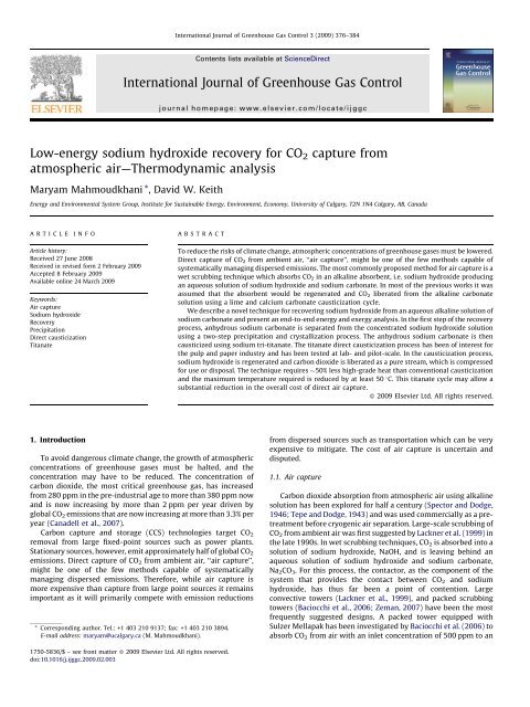
International Journal of Greenhouse Gas Control 3 (2009) 376–384<br />
Contents lists available at ScienceDirect<br />
International Journal of Greenhouse Gas Control<br />
journal homepage: www.elsevier.com/locate/ijggc<br />
<strong>Low</strong>-<strong>energy</strong> <strong>sodium</strong> <strong>hydroxide</strong> <strong>recovery</strong> <strong>for</strong> CO 2 capture from<br />
atmospheric air—Thermodynamic analysis<br />
Maryam Mahmoudkhani *, <strong>David</strong> W. <strong>Keith</strong><br />
Energy and Environmental System Group, Institute <strong>for</strong> Sustainable Energy, Environment, Economy, University of Calgary, T2N 1N4 Calgary, AB, Canada<br />
ARTICLE<br />
INFO<br />
ABSTRACT<br />
Article history:<br />
Received 27 June 2008<br />
Received in revised <strong>for</strong>m 2 February 2009<br />
Accepted 8 February 2009<br />
Available online 24 March 2009<br />
Keywords:<br />
Air capture<br />
Sodium <strong>hydroxide</strong><br />
Recovery<br />
Precipitation<br />
Direct causticization<br />
Titanate<br />
To reduce the risks of climate change, atmospheric concentrations of greenhouse gases must be lowered.<br />
Direct capture of CO 2 from ambient air, ‘‘air capture’’, might be one of the few methods capable of<br />
systematically managing dispersed emissions. The most commonly proposed method <strong>for</strong> air capture is a<br />
wet scrubbing technique which absorbs CO 2 in an alkaline absorbent, i.e. <strong>sodium</strong> <strong>hydroxide</strong> producing<br />
an aqueous solution of <strong>sodium</strong> <strong>hydroxide</strong> and <strong>sodium</strong> carbonate. In most of the previous works it was<br />
assumed that the absorbent would be regenerated and CO 2 liberated from the alkaline carbonate<br />
solution using a lime and calcium carbonate causticization cycle.<br />
We describe a novel technique <strong>for</strong> recovering <strong>sodium</strong> <strong>hydroxide</strong> from an aqueous alkaline solution of<br />
<strong>sodium</strong> carbonate and present an end-to-end <strong>energy</strong> and exergy analysis. In the first step of the <strong>recovery</strong><br />
process, anhydrous <strong>sodium</strong> carbonate is separated from the concentrated <strong>sodium</strong> <strong>hydroxide</strong> solution<br />
using a two-step precipitation and crystallization process. The anhydrous <strong>sodium</strong> carbonate is then<br />
causticized using <strong>sodium</strong> tri-titanate. The titanate direct causticization process has been of interest <strong>for</strong><br />
the pulp and paper industry and has been tested at lab- and pilot-scale. In the causticization process,<br />
<strong>sodium</strong> <strong>hydroxide</strong> is regenerated and carbon dioxide is liberated as a pure stream, which is compressed<br />
<strong>for</strong> use or disposal. The technique requires 50% less high-grade heat than conventional causticization<br />
and the maximum temperature required is reduced by at least 50 8C. This titanate cycle may allow a<br />
substantial reduction in the overall cost of direct air capture.<br />
ß 2009 Elsevier Ltd. All rights reserved.<br />
1. Introduction<br />
To avoid dangerous climate change, the growth of atmospheric<br />
concentrations of greenhouse gases must be halted, and the<br />
concentration may have to be reduced. The concentration of<br />
carbon dioxide, the most critical greenhouse gas, has increased<br />
from 280 ppm in the pre-industrial age to more than 380 ppm now<br />
and is now increasing by more than 2 ppm per year driven by<br />
global CO 2 emissions that are now increasing at more than 3.3% per<br />
year (Canadell et al., 2007).<br />
Carbon capture and storage (CCS) technologies target CO 2<br />
removal from large fixed-point sources such as power plants.<br />
Stationary sources, however, emit approximately half of global CO 2<br />
emissions. Direct capture of CO 2 from ambient air, ‘‘air capture’’,<br />
might be one of the few methods capable of systematically<br />
managing dispersed emissions. There<strong>for</strong>e, while air capture is<br />
more expensive than capture from large point sources it remains<br />
important as it will primarily compete with emission reductions<br />
* Corresponding author. Tel.: +1 403 210 9137; fax: +1 403 210 3894.<br />
E-mail address: maryam@ucalgary.ca (M. Mahmoudkhani).<br />
from dispersed sources such as transportation which can be very<br />
expensive to mitigate. The cost of air capture is uncertain and<br />
disputed.<br />
1.1. Air capture<br />
Carbon dioxide absorption from atmospheric air using alkaline<br />
solution has been explored <strong>for</strong> half a century (Spector and Dodge,<br />
1946; Tepe and Dodge, 1943) and was used commercially as a pretreatment<br />
be<strong>for</strong>e cryogenic air separation. Large-scale scrubbing of<br />
CO 2 from ambient air was first suggested by Lackner et al. (1999) in<br />
the late 1990s. In wet scrubbing techniques, CO 2 is absorbed into a<br />
solution of <strong>sodium</strong> <strong>hydroxide</strong>, NaOH, and is leaving behind an<br />
aqueous solution of <strong>sodium</strong> <strong>hydroxide</strong> and <strong>sodium</strong> carbonate,<br />
Na 2 CO 3 . For this process, the contactor, as the component of the<br />
system that provides the contact between CO 2 and <strong>sodium</strong><br />
<strong>hydroxide</strong>, has thus far been a point of contention. Large<br />
convective towers (Lackner et al., 1999), and packed scrubbing<br />
towers (Baciocchi et al., 2006; Zeman, 2007) have been the most<br />
frequently suggested designs. A packed tower equipped with<br />
Sulzer Mellapak has been investigated by Baciocchi et al. (2006) to<br />
absorb CO 2 from air with an inlet concentration of 500 ppm to an<br />
1750-5836/$ – see front matter ß 2009 Elsevier Ltd. All rights reserved.<br />
doi:10.1016/j.ijggc.2009.02.003
M. Mahmoudkhani, D.W. <strong>Keith</strong> / International Journal of Greenhouse Gas Control 3 (2009) 376–384 377<br />
outlet concentration of 250 ppm using a 2 M NaOH solution.<br />
Zeman (2007) however, selected a chamber filled with packing<br />
material that provides sufficient surface area <strong>for</strong> 50% capture rate<br />
from air with inlet concentration of 380 ppm with 1 M <strong>sodium</strong><br />
<strong>hydroxide</strong> solution.<br />
An alternative strategy, suggested by Storaloff et al. (2008),isto<br />
generate a fine spray of the absorbing solution <strong>for</strong> providing large<br />
surface to the air flow through an open tower. This strategy could<br />
have the potential to operate with a small pressure drop in air and<br />
avoids the capital cost of packing material. Storaloff et al. (2008)<br />
studied the feasibility of a NaOH spray-based contactor by<br />
estimating the cost and <strong>energy</strong> requirement per unit CO 2 captured.<br />
Storaloff et al. (2008) addressed the water loss, as a major<br />
concern in any aqueous air capture process and found that the<br />
water loss could be managed by adjusting of the NaOH<br />
concentration with temperature and humidity of air, i.e. the<br />
higher the concentration of <strong>sodium</strong> <strong>hydroxide</strong>, the lower is the<br />
water loss, e.g. using 7.2 M NaOH, at 15 8C and 65% relative<br />
humidity, water loss is eliminated.<br />
All of these processes produce a <strong>sodium</strong> carbonate solution<br />
which must be converted back to <strong>sodium</strong> <strong>hydroxide</strong> solution and<br />
carbon dioxide gas in order to close the loop. It should be noted that<br />
the contaminants from air might be an issue in air capture and<br />
these are the issues that must still be worked out, however, <strong>for</strong><br />
contaminants like SO 2 , the risk might not be so high as the<br />
concentration of SO 2 in too low in atmosphere, ranging from 20 ppt<br />
to 1 ppb.<br />
1.2. Caustic <strong>recovery</strong> <strong>for</strong> air capture<br />
Conversion of <strong>sodium</strong> carbonate into <strong>sodium</strong> <strong>hydroxide</strong>, socalled<br />
‘‘causticization’’ or ‘‘caustic <strong>recovery</strong>’’, is one of the oldest<br />
processes in industrial chemistry. In Kraft Pulping <strong>for</strong> paper<br />
making, wood is digested using <strong>sodium</strong> <strong>hydroxide</strong> to liberate<br />
cellulose and produce pulp. The remained solution, so-called<br />
‘‘black liquor’’, consists of mainly other organic material originated<br />
from wood (e.g. lignin), along with <strong>sodium</strong> carbonate. To convert<br />
<strong>sodium</strong> carbonate and recover NaOH the conventional causticization<br />
using lime has been used <strong>for</strong> almost a century.<br />
In conventional chemical <strong>recovery</strong>, Na 2 CO 3 is causticized with<br />
lime to <strong>for</strong>m NaOH and lime mud (CaCO 3 ), reaction (1). The<br />
conversion of Na 2 CO 3 to NaOH and regeneration of lime is a series<br />
of liquid–solid reactions, reactions (1)–(3), i.e. all involved calcium<br />
compounds are solids. Prior works on air capture with NaOH has<br />
focused on this <strong>recovery</strong> cycle (Baciocchi et al., 2006; Storaloff<br />
et al., 2008; Zeman, 2007).<br />
Na 2 CO 3 þ CaðOHÞ 2 $ 2NaOH þ CaCO 3 ;<br />
DH 100 C ¼ 5:3kJ=mol CO 2 (1)<br />
CaCO 3 $ CaO þ CO 2 ; DH 900 C ¼ 179 kJ=mol CO 2 (2)<br />
CaO þ H 2 O $ CaðOHÞ 2 ; DH 100 C ¼ 65 kJ=mol CO 2 (3)<br />
The enthalpy of the reaction <strong>for</strong> absorption of CO 2 from air into<br />
<strong>sodium</strong> <strong>hydroxide</strong> solution <strong>for</strong> a nominal 1 M solution and at 298 K<br />
and a pressure of 1 bar is 109.4 kJ/mol CO 2 which implies that to<br />
go from <strong>sodium</strong> carbonate to <strong>sodium</strong> <strong>hydroxide</strong> the thermodynamic<br />
minimum required <strong>energy</strong> is 109.4 kJ/mol CO 2 . Conventional<br />
causticization using lime requires a minimum of 179 kJ/mol<br />
CO 2 at standard T and P <strong>for</strong> reaction (2). Comparing the high<br />
temperature <strong>energy</strong> required to regenerate NaOH using conventional<br />
causticization with the thermodynamic minimum (109.4 kJ/<br />
mol CO 2 ) indicates that the required <strong>energy</strong> <strong>for</strong> conventional<br />
causticization is far beyond the thermodynamic minimum.<br />
As a tool <strong>for</strong> air capture, conventional causticization has, several<br />
major drawbacks including:<br />
A comparatively large demand <strong>for</strong> high temperature heat<br />
compared to thermodynamic minimum to go from Na 2 CO 3 to<br />
NaOH, i.e. 109.4 kJ/mol,<br />
a causticization efficiency limited to 80–90% in a typical Kraft<br />
<strong>recovery</strong> cycle and<br />
the alkalinity of the regenerated NaOH solution is limited by the<br />
causticization reaction to about 1 mol/L.<br />
Methods introducing alternative causticization processes have<br />
been widely investigated in pulp and paper industry. Autocausticization<br />
1 (using borate), direct causticization 2 (using iron<br />
oxide or titanium dioxide) or partially auto- or direct causticization<br />
has been addressed in number of literature (Covey, 1982;<br />
Hoddenbagh et al., 2002; Kiiskilä, 1979a,b; Nagano et al., 1974;<br />
Maddern, 1986; Palm and Theliander, 1997; Sinquefield et al.,<br />
2004; Yusuf and Cameron, 2004; Zou, 1991). The titanate<br />
causticization process has been studied as an addition to or<br />
replacement <strong>for</strong> the calcination process used in Kraft paper making<br />
<strong>for</strong> a few decades. Titanate process has been tested in small-scale<br />
fluidized bed, laboratory conditions and pilot-scale but has not yet<br />
been applied to commercial scale. This research has been driven by<br />
the needs of the pulp industry; there<strong>for</strong>e it is focused on titanates<br />
reactions in the presence of black liquor. For this reason knowledge<br />
of the thermodynamics of the pure state reactions is not<br />
systematic.<br />
Studies of the direct causticization of <strong>sodium</strong> carbonate with<br />
titanium dioxide have been carried out by Chen and van Heiningen<br />
(2006), Kiiskilä (1979a,b), Nohlgren (2002), Palm and Theliander<br />
(1997), Zeng and van Heiningen (1997) and Zou (1991). Depending<br />
on the feed molar ratio and temperature, the reaction between<br />
Na 2 CO 3 and TiO 2 leads to various <strong>sodium</strong> titanates as products. It<br />
has been found that the main decarbonization reaction in the<br />
direct causticization based on TiO 2 is the reactions between<br />
Na 2 CO 3 and Na 2 O3TiO 2 , i.e. reactions (4a) and (4b) (Kiiskilä,<br />
1979a,b; Nohlgren, 2002; Zou, 1991).<br />
7Na 2 CO 3ðsÞ þ 5ðNa 2 O 3TiO 2 Þ ðsÞ $ 3ð4Na 2 O 5TiO 2 Þ ðsÞ þ 7CO 2ðgÞ ;<br />
DH 850 C;s ¼ 90 kJ=mol CO 2<br />
Na 2 CO 3ðsÞ ! Na 2 CO 3ðlÞ ; DH 851 C;s ¼ 25 kJ=mol CO 2<br />
7Na 2 CO 3ðlÞ þ 5ðNa 2 O 3TiO 2 Þ ðsÞ $ 3ð4Na 2 O 5TiO 2 Þ ðsÞ þ 7CO 2ðgÞ ;<br />
DH 850 C;l ¼ 65 kJ=mol CO 2<br />
(4a)<br />
(4b)<br />
Note that the overall reaction enthalpy is 90 kJ/mol CO 2 ,<br />
weather the reaction is per<strong>for</strong>med below or above melting point of<br />
Na 2 CO 3 (65 + 25 = 90 kJ/mol). Titanate process requires 50% less<br />
high temperature <strong>energy</strong> than lime process, however in both<br />
processes there are issues with moisture contents and heat<br />
<strong>recovery</strong>.<br />
The <strong>sodium</strong> penta-titanate, 4Na 2 O5TiO 2 , is then hydrolyzed,<br />
Eq. (5), in a leaching unit at a temperature of about 100 8C, to<br />
1 The term ‘‘auto-causticization’’ is used when the reaction product is water<br />
soluble and the decarbonizing agent is carried out through the entire pulping and<br />
<strong>recovery</strong> cycle as a caustic solution. In this process the caustic solution causticized<br />
itself during combustion or gasification.<br />
2 The term direct causticization is used when the reaction product is insoluble in<br />
a caustic solution and the decarbonizing agent is separated from the caustic<br />
solution and is not carried through the liquor cycle. In this process the<br />
decarbonizing agent is added and subsequently removed.
378<br />
M. Mahmoudkhani, D.W. <strong>Keith</strong> / International Journal of Greenhouse Gas Control 3 (2009) 376–384<br />
Fig. 1. Block diagram <strong>for</strong> chemical <strong>recovery</strong> using titanates in air capture.<br />
<strong>sodium</strong> <strong>hydroxide</strong> and <strong>sodium</strong> tri-titanate, which the latter is<br />
recycled to the causticization unit.<br />
3ð4Na 2 O 5TiO 2 Þ ðsÞ þ 7H 2 O $ 5ðNa 2 O 3TiO 2 Þ ðsÞ þ 14NaOH ðaqÞ ;<br />
DH 100 C ¼ 15:2kJ=mol CO 2 (5)<br />
The conventional titanate process cannot be directly applied to<br />
air capture because it requires pure and dry anhydrous <strong>sodium</strong><br />
carbonate, and it is not obvious how to extract solid <strong>sodium</strong><br />
carbonate from the rich solution of <strong>sodium</strong> <strong>hydroxide</strong> and <strong>sodium</strong><br />
carbonate coming from the air capture contactor. This solution<br />
would typically have 1–4 M NaOH and less than 1 M of dissolved<br />
Na 2 CO 3 . The major focus of this work, there<strong>for</strong>e, is on separation of<br />
anhydrous <strong>sodium</strong> carbonate from Na 2 CO 3 -NaOH feed solution,<br />
and preparation of a well-mixed stream of solid <strong>sodium</strong> carbonate<br />
and <strong>sodium</strong> tri-titanate, the latter used as a reagent <strong>for</strong><br />
decarbonizing of <strong>sodium</strong> carbonate via reaction [(4a) and (4b)].<br />
This is the crucial step necessary <strong>for</strong> applying the titanate process<br />
to air capture. After describing the process <strong>for</strong> recovering solid<br />
Na 2 CO 3 , we present an end-to-end <strong>energy</strong> and exergy analysis <strong>for</strong><br />
the regeneration of NaOH via direct causticization using titanate as<br />
an alternative to conventional causticization is assessed.<br />
2. Process description<br />
Fig. 1 illustrates a simplified schematic sketch of the proposed<br />
process <strong>for</strong> the regeneration step in capturing CO 2 from air which is<br />
viewed as a two step process requiring a precipitation and a<br />
decarbonization step. The more detailed flow sheet is illustrated in<br />
Fig. 2.<br />
The precipitation unit is a two-stage crystallization/precipitation<br />
unit <strong>for</strong> precipitating anhydrous <strong>sodium</strong> carbonate from<br />
concentrated alkaline aqueous solution. In the first crystallization<br />
stage, <strong>sodium</strong> carbonate decahydrate is crystallized from concentrated<br />
alkaline aqueous solution, and in second stage,<br />
anhydrous <strong>sodium</strong> carbonate is precipitated from a saturated<br />
<strong>sodium</strong> carbonate aqueous solution simultaneously as the <strong>sodium</strong><br />
Fig. 2. Process design <strong>for</strong> air capture using titanate chemical <strong>recovery</strong> cycle.
M. Mahmoudkhani, D.W. <strong>Keith</strong> / International Journal of Greenhouse Gas Control 3 (2009) 376–384 379<br />
penta-titanate is hydrolyzed at elevated temperature. The hydrolysis<br />
of <strong>sodium</strong> penta-titanate adds aqueous <strong>sodium</strong> <strong>hydroxide</strong> to<br />
the solution which lowers the solubility of <strong>sodium</strong> carbonate<br />
<strong>for</strong>cing the precipitation of <strong>sodium</strong> carbonate.<br />
At temperatures above about 100 8C, the precipitated <strong>sodium</strong><br />
carbonate is expected to be in the anhydrous <strong>for</strong>m needed <strong>for</strong> the<br />
reaction with tri-titanate reducing the process <strong>energy</strong> requirements.<br />
The <strong>sodium</strong> <strong>hydroxide</strong> is regenerated and recycled to the contactor<br />
and the solid anhydrous <strong>sodium</strong> carbonate is then causticized using<br />
direct causticization with titanate, in the causticization unit where<br />
CO 2 is liberated from <strong>sodium</strong> carbonated.<br />
2.1. Separation of <strong>sodium</strong> carbonate from concentrated<br />
alkaline feed solution<br />
If <strong>sodium</strong> carbonate is to be converted to <strong>sodium</strong> <strong>hydroxide</strong> via<br />
direct causticization process, it must first be separated from<br />
concentrated alkaline solution in a pure solid stream. This is<br />
necessary because (1) the causticization reaction with titanium<br />
dioxide or recycled <strong>sodium</strong> tri-titanate is a solid state or solidsmelt<br />
state reaction and presence of aqueous phase along with<br />
<strong>sodium</strong> carbonate dramatically increases the <strong>energy</strong> demand due<br />
to evaporation, (2) presence of <strong>sodium</strong> <strong>hydroxide</strong> along with<br />
<strong>sodium</strong> carbonate in the causticization reactor would cause<br />
<strong>for</strong>mation of sticky particles which would lead to corrosion, (3)<br />
presence of <strong>sodium</strong> <strong>hydroxide</strong> decreases melting point of <strong>sodium</strong><br />
carbonate (according to NaOH–Na 2 CO 3 phase diagram).<br />
Be<strong>for</strong>e describing the process design, we review the data on the<br />
solubility of <strong>sodium</strong> carbonate in water and in <strong>hydroxide</strong> and<br />
examine the influence of temperature and <strong>hydroxide</strong> ions<br />
concentration on solubility.<br />
2.1.1. Solubility data <strong>for</strong> <strong>sodium</strong> carbonate–water system<br />
The solubility data, solid phases and transition temperatures <strong>for</strong><br />
<strong>sodium</strong> carbonate–water system were reviewed and collated by<br />
Kobe and Sheehy as early as 1948. Sodium carbonate, whose<br />
anhydrous and monohydrated <strong>for</strong>ms dissolve exothermically,<br />
shows a complex pattern of solubility. In the region in which<br />
the equilibrium salt phase is anhydrous, its solubility decreases<br />
with increasing temperature, see Fig. 3. Transition points in<br />
<strong>sodium</strong> carbonate–water system are shown in Table 1, in which<br />
the temperature at transition point between <strong>sodium</strong> carbonate<br />
monohydrate and <strong>sodium</strong> anhydrous carbonate is 109 8C.<br />
Sodium carbonate can be crystallized as various hydrates. The<br />
transition temperature between <strong>sodium</strong> carbonate monohydrate<br />
and anhydrous <strong>sodium</strong> carbonate is higher than the boiling point of<br />
Fig. 3. Solubility of <strong>sodium</strong> carbonate in water (Kobe and Sheehy, 1948). The two<br />
labeled dots provide a schematic indication of the process <strong>for</strong> separating anhydrous<br />
Na 2 CO 3 in the method we propose here. A solution of Na 2 CO 3 at point ‘A’, is cooled<br />
to point ‘B’ precipitating decahydrate (Na 2 CO 3 10H 2 O). The principal concept <strong>for</strong><br />
separating Na 2 CO 3 from alkaline solution will be similar to what is shown in this<br />
figure.<br />
Table 1<br />
Temperature at transit points in Na 2 CO 3 –H 2 O system (Kobe and Sheehy, 1948).<br />
Phases<br />
Temp. (8C)<br />
Na 2 CO 3 10H 2 O–ice 2.1<br />
Na 2 CO 3 10H 2 O–Na 2 CO 3 7H 2 O 32.00<br />
Na 2 CO 3 10H 2 O–Na 2 CO 3 H 2 O 32.96<br />
Na 2 CO 3 7H 2 O–Na 2 CO 3 H 2 O 35.37<br />
Boiling point 104.8<br />
Na 2 CO 3 H 2 O–Na 2 CO 3 109<br />
a saturated <strong>sodium</strong> carbonate solution (30 wt%). Crystallization of<br />
anhydrous <strong>sodium</strong> carbonate starts at T 118 8C from a 30 wt%<br />
(2.8 M) <strong>sodium</strong> carbonate concentration based on solubility data<br />
in <strong>sodium</strong> carbonate–water system (see Fig. 3 and Table 1).<br />
Different methods can be applied to produce anhydrous <strong>sodium</strong><br />
carbonate from a pure aqueous solution. Operating under<br />
pressurized condition is one way to raise the boiling temperature<br />
(105.7 8C) above the transition temperature (109 8C). The other<br />
way is to crystallize <strong>sodium</strong> carbonate at lower temperatures<br />
either as <strong>sodium</strong> carbonate decahydrate (Na 2 CO 3 10H 2 O) or<br />
monohydrate (Na 2 CO 3 H 2 O). The hydrates are then calcined at<br />
150–200 8C to obtain the anhydrous <strong>for</strong>m (Oosterhof, 2001). The<br />
thermal dehydration of <strong>sodium</strong> carbonate hydrates is, however,<br />
considerably endothermic; the values of 52.67 and 58.77 kJ/mol<br />
H 2 O has been cited <strong>for</strong> decahydrate and monohydrate respectively.<br />
These values are appreciably greater than the 44 kJ/mol heat of<br />
vaporization of liquid water at 298 K. An alternative crystallization<br />
method was addressed by Weingaertnet et al. (1991) and<br />
Oosterhof et al. (1999, 2001), in which a suitable anti-solvent is<br />
used to decrease the solubility of the salt and also to lower the<br />
water activity. This means that the transition temperature is<br />
lowered and anhydrate can be produced directly at lower<br />
temperatures, even below the boiling point of the solution.<br />
Addition of ethylene glycol by 25 wt%, <strong>for</strong> example, would increase<br />
the boiling point of the solution from 105.7 to 106.8 8C and lower<br />
the transition point from 109 to 105.7 8C (Oosterhof, 2001).<br />
2.1.2. Solubility data <strong>for</strong> <strong>sodium</strong> carbonate–<strong>sodium</strong> <strong>hydroxide</strong> system<br />
The ternary system of Na 2 CO 3 –NaOH–H 2 O has been studied as<br />
early as 1923 by Freeth and the solubility of carbonate salts, in<br />
general, was found to drop in the presence of <strong>hydroxide</strong> ions. A<br />
number of studies have been done on solubility of <strong>sodium</strong><br />
carbonate in Na 2 CO 3 –NaOH–H 2 O system <strong>for</strong> which the data is<br />
edited and presented by Silcock (1963). Konigsberger (2001) also<br />
presented the results of a thermodynamical method which would<br />
predict the influence of <strong>sodium</strong> <strong>hydroxide</strong> concentration in the<br />
solution on the solubility of <strong>sodium</strong> carbonate. The model was<br />
verified <strong>for</strong> the solubility of monohydrate by experimental data.<br />
The result from Konigsberger’s work is in agreement with earlier<br />
studies on solubility data <strong>for</strong> <strong>sodium</strong> carbonate. Fig. 4 illustrates a<br />
summary of the literature data on solubility of <strong>sodium</strong> carbonate at<br />
different temperature and concentrations of NaOH solution, 5%,<br />
10% and 17% corresponding to 1.5, 3 and 5 M NaOH.<br />
As it is shown in Fig. 4, in general, the solubility curve <strong>for</strong><br />
<strong>sodium</strong> carbonate in presence of <strong>sodium</strong> <strong>hydroxide</strong> in the solution<br />
follows the same pattern as the solubility curve <strong>for</strong> Na 2 CO 3 –water<br />
system and approximately the solubility product rule.<br />
The transition temperature of <strong>sodium</strong> carbonate monohydrate<br />
and anhydrous <strong>sodium</strong> carbonate is influenced by the concentration<br />
of <strong>sodium</strong> <strong>hydroxide</strong>. Keene and Syracuse (1938) showed that<br />
addition of other soluble substances, e.g. <strong>sodium</strong> <strong>hydroxide</strong>, to a<br />
saturated aqueous solution of <strong>sodium</strong> carbonate will cause a<br />
reduction in its vapor pressure which results in an elevation of its<br />
normal boiling point and in reduction of the transition temperature<br />
from <strong>sodium</strong> carbonate monohydrate to anhydrous <strong>sodium</strong><br />
carbonate, see Fig. 5.
380<br />
M. Mahmoudkhani, D.W. <strong>Keith</strong> / International Journal of Greenhouse Gas Control 3 (2009) 376–384<br />
Fig. 4. Solubility of <strong>sodium</strong> carbonate in water and 1.5, 3 and 5 M NaOH solution.<br />
The separated crystals of <strong>sodium</strong> carbonate decahydrate are dissolved in water at<br />
30 8C to produce a saturated solution indicated by the point ‘C’. The solution is<br />
heated to about 100 8C (point ‘D’) at which due to hydrolysis of added <strong>sodium</strong><br />
penta-titanate, NaOH is leached out; this would in turn cause the <strong>sodium</strong> carbonate<br />
to be precipitated as anhydrous <strong>sodium</strong> carbonate. Depending on the concentration<br />
of leached NaOH, the solubility of <strong>sodium</strong> carbonate would drop to points E, F or G.<br />
2.1.3. Process design <strong>for</strong> the separation of anhydrous <strong>sodium</strong><br />
carbonate from alkaline solution<br />
Earlier studies on obtaining anhydrous <strong>sodium</strong> carbonate, deal<br />
mostly with separation of anhydrous <strong>sodium</strong> carbonate from crude<br />
<strong>sodium</strong> sesquicarbonate or brine solution. The precipitation of<br />
<strong>sodium</strong> carbonate from an aqueous solution of <strong>sodium</strong> carbonate<br />
and <strong>sodium</strong> <strong>hydroxide</strong> has not been addressed in the literature. In<br />
this paper, there<strong>for</strong>e, we propose a novel method to precipitate a<br />
pure anhydrous <strong>sodium</strong> carbonate from a concentrated alkaline<br />
solution, e.g. an aqueous mixture of 1–4 M NaOH and 1–2 M<br />
Na 2 CO 3 .<br />
The method requires two precipitation steps, in the first <strong>sodium</strong><br />
carbonate is precipitated as <strong>sodium</strong> carbonate decahydrate,<br />
Na 2 CO 3 10H 2 O, from a saturated solution of Na 2 CO 3 –NaOH by<br />
means of a temperature swing. The concentration of dissolved<br />
Na 2 CO 3 in the reservoir is a critical operational parameter; Table 2<br />
shows a practical range of carbonate concentration in the solution<br />
as a function of temperature. Running the reservoir with carbonate<br />
close to saturation minimizes the <strong>energy</strong> required <strong>for</strong> the<br />
temperature swing, but if the concentration is too close to<br />
saturation, carbonate may precipitate in the reservoir tank. The<br />
two labeled dots, A to B, in Fig. 3 illustrate the schematic indication<br />
of <strong>sodium</strong> carbonate decahydrate precipitation. Although, the<br />
separation process is sketched <strong>for</strong> Na 2 CO 3 –water system, the<br />
separation process <strong>for</strong> Na 2 CO 3 from Na 2 CO 3 –NaOH–H 2 O would<br />
follow the same concept.<br />
Fig. 5. Dependency of transition T between monohydrate and anhydrous on NaOH<br />
concentration. Note: the figure is redrawn from Fig. 1 in Keene and Syracuse (1938).<br />
While crystallization of <strong>sodium</strong> carbonate decahydrate can be<br />
assured by imposing a sufficiently large temperature swing, a<br />
practical large-scale process requires that crystals be grown to a<br />
large enough size that they can be cost effectively removed from<br />
solution with a minimum of solution carry-over. Different<br />
crystallizer designs via cooling process are available. A draft tube<br />
baffle (DTB) crystallizer from Swenson Crystallization Equipment<br />
has proven to be very useful <strong>for</strong> crystallizing <strong>sodium</strong> carbonate<br />
decahydrate from aqueous <strong>sodium</strong> carbonate. The same kind of<br />
crystallizer might efficiently crystallize <strong>sodium</strong> carbonate decahydrate<br />
from the reservoir, e.g. aqueous <strong>sodium</strong> carbonate and<br />
<strong>sodium</strong> <strong>hydroxide</strong>. The DTB crystallizer includes a baffle section<br />
surrounding a suspended magma of growing crystals from which a<br />
stream of mother liquor is removed containing excess fine crystals.<br />
These fines can be destroyed by adding heat (as in an evaporative<br />
crystallizer) or by adding water or unsaturated feed solution. The<br />
magma is suspended by means of a large, slow-moving propeller<br />
circulator which fluidizes the suspension and maintains relatively<br />
uni<strong>for</strong>m growth zone conditions. Another design by DHV Water AB<br />
is a pellet reactor type crystallizer which is called ‘‘crystalactor’’.<br />
The crystalactor is filled with suitable seeding material to provide<br />
nuclei <strong>for</strong> the crystallization of <strong>sodium</strong> carbonate decahydrate. The<br />
crystalactor has successfully been in operation <strong>for</strong> metal and anion<br />
<strong>recovery</strong> from waste water (Giensen and van der Moldeh, 1996).<br />
This type of crystallizer has also been studied <strong>for</strong> precipitation of<br />
other metal-carbonates. Damien and Lewis (2001) studied the<br />
carbonate precipitation of nickel in pellet reactor and Lewis (2006)<br />
investigated the precipitation of nickel hydroxyl-carbonate using<br />
the fluidized pellet reactor. The fluidized bed provides a very large<br />
crystallization surface and in a fast controlled reaction almost all<br />
the anion crystallizes directly from the solution into the crystal<br />
lattice. There<strong>for</strong>e, pure, almost moisture-free (moisture content of<br />
only 5–10%) salt are produced after atmospheric drying. The<br />
crystalactor has not been tested <strong>for</strong> crystallization of <strong>sodium</strong><br />
carbonate decahydrate.<br />
The next step in our process, is to dissolve pure crystals of<br />
Na 2 CO 3 10H 2 O in warm water (at temperature above 30 8C) to a<br />
total concentration of 2.8 M (30 wt%) providing a pH level of<br />
about 12. It should be mentioned that the pH level is all the process<br />
units in our study is high enough to prevent co-crystallization of<br />
any <strong>sodium</strong> bicarbonate crystals during the process (i.e. <strong>sodium</strong><br />
bicarbonate precipitates at pH between 6 and 9, while the pH level<br />
<strong>for</strong> all the process is always above 12). In order to precipitate<br />
anhydrous <strong>sodium</strong> carbonate from this aqueous solution, the<br />
solution should be heated to temperatures above 118 8C. However,<br />
as stated earlier, the boiling point of a 30 wt% <strong>sodium</strong> carbonate<br />
solution is 105.7 8C. To avoid boiling the system might be<br />
pressurized. Crystallization of anhydrous <strong>sodium</strong> carbonate can<br />
be accomplished by removing water using and evaporative process<br />
or reverse osmosis. Alternatively, it might be achieved by use of<br />
anti-solvents; however, the addition of anti-solvents is probably<br />
not applicable to air capture process because of hazardous organic<br />
vapors emissions in air via entering a few percent of organic antisolvents<br />
into alkaline solution which is sprayed in the contactor.<br />
The alternative process is to introduce <strong>sodium</strong> <strong>hydroxide</strong> into<br />
the solution when the solution is heated to temperature close but<br />
below the boiling point. This would significantly drop the solubility<br />
and anhydrous or a mixture of anhydrous and monohydrate<br />
Na 2 CO 3 would precipitate, e.g. dropping the solubility from point D<br />
to G in Fig. 4, when concentration of NaOH in the solution increases<br />
to 5 M at temperature of about 100 8C. Based on Keene and<br />
Syracuse’s studies, the transition temperature between <strong>sodium</strong><br />
carbonate monohydrate and anhydrous <strong>sodium</strong> carbonate would<br />
shift from 109 8C inNa 2 CO 3 –water solution to about 97 8C ina<br />
Na 2 CO 3 –NaOH–water system with a final concentration of about<br />
5 M of NaOH. The phase boundary of <strong>sodium</strong> carbonate would,
M. Mahmoudkhani, D.W. <strong>Keith</strong> / International Journal of Greenhouse Gas Control 3 (2009) 376–384 381<br />
Table 2<br />
The changes in concentrations of carbonate when NaOH is present at different concentrations.<br />
Ambient T (8C)<br />
NaOH concentration<br />
in reservoir (mol/L)<br />
Maximum carbonate<br />
concentration in (mol/L)<br />
T swing<br />
DT (8C)<br />
Carbonate concentration<br />
out (mol/L)<br />
Precipitated<br />
carbonate, DC<br />
30 5 0.9 20 0.42 0.48<br />
25 5 0.85 15 0.42 0.43<br />
20 3 1 0.55 0.45<br />
5 0.75 10 0.42 0.33<br />
15 3 0.75 0.55 0.2<br />
5 0.55 5 0.42 0.13<br />
there<strong>for</strong>e, shift to permit the crystallization to be carried out at<br />
atmospheric pressure while still growing crystals of anhydrous<br />
<strong>sodium</strong> carbonate.<br />
To provide a high concentration of NaOH in a saturated solution<br />
of <strong>sodium</strong> carbonate at elevated temperature, we describe a novel<br />
process in which anhydrous <strong>sodium</strong> carbonate is precipitated<br />
simultaneously as the <strong>sodium</strong> penta-titanate from decarbonization<br />
unit is hydrolyzed to leach <strong>sodium</strong> <strong>hydroxide</strong> out, reaction (5).<br />
The leaching of <strong>sodium</strong> <strong>hydroxide</strong> from <strong>sodium</strong> penta-titanate has<br />
been studied by Richards and Theliander (1999) and the influence<br />
of temperature and initial concentration on leaching rate was<br />
addressed. It was found that the leaching reaction, reaction (5), is<br />
an endothermic reaction, DH = 15.2 kJ/mol CO 2 , and that by<br />
presenting experimental data at temperatures of 70 and 100 8C,<br />
it was shown that leaching rate at about 100 8C and <strong>for</strong> the studied<br />
experimental time, can be high enough to produce a maximum 5 M<br />
aqueous solution of <strong>sodium</strong> <strong>hydroxide</strong>. The influence of other<br />
soluble compounds, e.g. carbonate ions on the hydrolysis of<br />
<strong>sodium</strong> penta-titanate, has, however, not been studied in the<br />
literature.<br />
The proposed process works as follows: penta-titanate is added<br />
to the 2.8 M saturated <strong>sodium</strong> carbonate solution at temperatures<br />
of 100 8C. The <strong>sodium</strong> penta-titanate hydrolyzes releasing<br />
NaOH which drives the <strong>sodium</strong> carbonate out of solution. The<br />
leaching of <strong>sodium</strong> <strong>hydroxide</strong> would shift the solubility curve of<br />
<strong>sodium</strong> carbonate as well as the transition temperature of <strong>sodium</strong><br />
carbonate monohydrate and anhydrous <strong>sodium</strong> carbonate. We<br />
per<strong>for</strong>med a preliminary laboratory studies <strong>for</strong> the simultaneous<br />
leaching and precipitation reactions and found that the <strong>sodium</strong><br />
<strong>hydroxide</strong> can be leached out from <strong>sodium</strong> penta-titanate, and<br />
drive the anhydrous <strong>sodium</strong> carbonate to precipitate out from the<br />
solution. The concentration of <strong>sodium</strong> <strong>hydroxide</strong> was controlled so<br />
that a 3 M <strong>hydroxide</strong> solution is produced and the anhydrous<br />
<strong>sodium</strong> carbonate was precipitated at temperature of 103 8C. The<br />
crystalline structure of the precipitates, i.e. anhydrous <strong>sodium</strong><br />
carbonate and <strong>sodium</strong> tri-titanate was analyzed by means of XRD.<br />
More detailed experimental data will be discussed in a separate<br />
paper.<br />
2.2. Decarbonation of <strong>sodium</strong> carbonate via direct causticization<br />
Thermodynamics of titanate reaction has been widely studied<br />
as early as 1979 by Kiiskilä. Zou (1991) showed that the lower limit<br />
<strong>for</strong> reaction temperature is 840 8C in order to achieve sufficiently<br />
high reaction rates due to reaction (4a) under the applied<br />
experimental conditions in that study. At temperatures above<br />
the melting point of <strong>sodium</strong> carbonate, the enthalpy of reaction<br />
(4b) was reported to be 65 kJ/mol CO 2 (Nohlgren, 2002), whereas<br />
at temperatures below melting point and above 840 8C, the<br />
enthalpy of reaction (4a) is 90 kJ/mol CO 2 . The enthalpy of fusion<br />
<strong>for</strong> Na 2 CO 3 is 25.7 kJ/mol, which is approximately equal to the<br />
difference between the enthalpy of reaction (4a) and (4b), above<br />
and below the melting point. So the net enthalpy of reaction is<br />
about the same in either case.<br />
After a thorough thermodynamical analysis, we found that<br />
although the reaction can be carried out in solid state, but at<br />
temperatures slightly above the melting point (860 8C), the total<br />
<strong>energy</strong> requirement <strong>for</strong> heating the reactant and the reaction is 3%<br />
less than <strong>for</strong> temperatures below melting point. Moreover, at<br />
temperatures slightly above the melting point, the total <strong>energy</strong><br />
that can be recovered from cooling of the products is 3% more<br />
than <strong>for</strong> the temperatures below melting point. This would, in turn,<br />
lead to 6% more <strong>energy</strong> efficiency when causticization is carried<br />
out at temperatures slightly above the melting point. The reaction<br />
rate is also higher at temperature slightly above melting point,<br />
which is of great importance <strong>for</strong> the residence time in the fluidized<br />
bed reactor.<br />
The parameters influencing the kinetics of reaction (5) are<br />
addressed to be the particle size of both <strong>sodium</strong> carbonate and<br />
titanium dioxide and molar ratio of titanium dioxide and <strong>sodium</strong><br />
carbonate (TiO 2 /Na 2 CO 3 ). Zou (1991) found that all of the <strong>sodium</strong><br />
carbonate is converted below its melting point (858 8C) within a<br />
few minutes <strong>for</strong> particle sizes of <strong>sodium</strong> carbonate and<br />
TiO 2 < 25 mm and <strong>for</strong> TiO 2 /Na 2 CO 3 = 1.25, indicating that the<br />
reaction can be carried out successfully in the solid state, this was<br />
also confirmed by Nohlgren (2002). However, when larger particle<br />
sizes of <strong>sodium</strong> carbonate and TiO 2 , e.g. 63 mm (Kiiskilä, 1979), or<br />
smaller molar ratio, e.g. TiO 2 /Na 2 CO 3 =1(Zou, 1991), was used, the<br />
causticization reaction was slower than the previous cases at<br />
temperatures below <strong>sodium</strong> carbonate melting point.<br />
Besides the parameters discussed above, the partial pressure of<br />
CO 2 in the reaction atmosphere seems to influence the reaction<br />
kinetics of (4a) and (4b) too. The mechanism is not yet clearly<br />
understood. Nohlgren and Sinquefield (2004), Nohlgren et al.<br />
(2004) and Sinquefield (2005) reported a retarding effect of CO 2<br />
partial pressure on reaction rate. A thorough investigation of the<br />
mechanism <strong>for</strong> the influence of CO 2 partial pressure on titanate<br />
reaction is required, because <strong>for</strong> the purpose of this paper, we<br />
would rather to separate a CO 2 stream at partial pressure of about<br />
15 bar from the fluidized bed reactor. This would simplify the<br />
compression of separated CO 2 to higher pressure of about<br />
1005 bar.<br />
Design and process engineering of the system <strong>for</strong> heating the<br />
mixed carbonate/titanate particles is beyond the scope of this<br />
paper. In this section we provide speculation about two possible<br />
design alternatives that provide <strong>for</strong> heat and CO 2 <strong>recovery</strong>.<br />
Highly efficient kilns <strong>for</strong> heating fine particles to temperatures<br />
above that required here have been developed <strong>for</strong> lime production.<br />
The so-called ‘D’ kilns developed by the Italian lime kiln<br />
manufacturer, Cimprogetti, <strong>for</strong> example have demonstrated thermal<br />
efficiencies above 90% in large-scale applications. The<br />
efficiency comes from a counter flow design in which the particles<br />
drop through upward flowing gas. In the upper section of the kiln<br />
the cool particles are heated by the hot exhaust gases creating a
382<br />
M. Mahmoudkhani, D.W. <strong>Keith</strong> / International Journal of Greenhouse Gas Control 3 (2009) 376–384<br />
counter current heat exchanger. The calcination reaction proceeds<br />
in the middle of the kiln. In the lower section of the kiln the hot<br />
particles fall through the incoming air preheating it. It seems<br />
plausible that similar kiln designs could be readily adapted to drive<br />
the tri-titanate to penta-titanate reaction, although this design<br />
would not be directly applicable to particles in the size range<br />
discussed above.<br />
The most conservative approach would be to use natural gas<br />
fired in air as a heat source and then to capture the CO 2 using a<br />
post-combustion process such as amines or chilled ammonia from<br />
the exhaust gases. This approach would require minimal adaptation<br />
of existing kiln designs, and would presumably, carry the<br />
minimum technical risk. However the use of post-combustion<br />
capture would demand an efficiency penalty and would add capital<br />
cost.<br />
Alternatively, the <strong>energy</strong> demands of the titanate process are<br />
sufficiently low that it might make sense to use a natural gas fired,<br />
indirectly heated kiln in which the CO 2 from the gas combustion<br />
was not recovered. This is feasible because, <strong>for</strong> an efficient kiln, five<br />
times less CO 2 is produced by combustion of the gas than is<br />
extracted from air.<br />
A more advanced and perhaps more cost-effective design would<br />
use recirculating CO 2 into which heat introduced by an ‘‘oxyfuel’’<br />
mixture of oxygen and natural gas or syngas. The design of such<br />
systems could be adapted from the many design studies <strong>for</strong> oxyfuel<br />
coal fired power plants which are now being applied at scales of<br />
greater than 30 MW (Vattenfall). In this case the primary operating<br />
gas would be CO 2 at a pressure of atmospheric or above. The<br />
presence of CO 2 at atmospheric pressure might, however, cause<br />
problems in the titanate kinetics. At this step of research on<br />
titanate process, this is not yet fully understood.<br />
A still more advanced design would use indirect heat provided<br />
by a high temperature gas cooled reactor (HTGR). The second<br />
generation of HTGR reactors is currently being developed by<br />
several companies including PBMR, AREVA, and General Atomics.<br />
The first commercial scale passively safe PBRM reactor is expected<br />
to start construction in 2009. In these reactors the primary loop<br />
helium temperature is 900 8C, and the secondary loop temperature<br />
can be above 850 8C. It might there<strong>for</strong>e be practical to drive the<br />
titanate reactions using indirect heat provided by the secondary<br />
helium loop from an HTGR. In this design essentially the only gas<br />
inside the kiln would be CO 2 since no water would introduced by<br />
combustion as is the case <strong>for</strong> oxyfuel.<br />
HTGRs arguably could provide the lowest cost source of carbon<br />
neutral high-grade heat (MIT Report, 2003). If HTGRs are the power<br />
source, then the titanate process described here has another<br />
advantage, others in <strong>energy</strong> efficiency, over the calcination process<br />
because that titanate process can be operated at temperatures as<br />
low as 800 8C, whereas the calcination process requires temperatures<br />
of 950 8C (assuming atmospheric pressure CO 2 ). Current<br />
HTGR designs cannot practically supply heat at 950 8C.<br />
3. Energy and exergy analysis<br />
Richards et al (2004) and Richards et al. (2007) per<strong>for</strong>med a<br />
thermodynamical evaluation <strong>for</strong> the conventional causticization<br />
and the direct causticization using titanates and found that the<br />
process with highest potential from both <strong>energy</strong> and <strong>energy</strong><br />
equality perspective is the titanate process. It should be mentioned<br />
that in their studies solid <strong>sodium</strong> carbonate was used to per<strong>for</strong>m a<br />
fair comparison between the two processes.<br />
In this section, we show the results of the <strong>energy</strong> and exergy<br />
analysis <strong>for</strong> the <strong>recovery</strong> cycle using titanate in which <strong>sodium</strong><br />
carbonate and lean <strong>sodium</strong> <strong>hydroxide</strong> enters the cycle and carbon<br />
dioxide and rich <strong>sodium</strong> <strong>hydroxide</strong> leaves the cycle as the<br />
products. The other substances are subjected to be recycled<br />
between the different units. Note that the starting point <strong>for</strong> <strong>sodium</strong><br />
carbonate is the aqueous alkaline solution of Na 2 CO 3 –NaOH from<br />
the feed solution. The <strong>energy</strong> analysis <strong>for</strong> the CO 2 absorption<br />
section, ‘‘contactor’’, can be found elsewhere (Storaloff et al., 2008).<br />
In this paper, a total <strong>energy</strong> requirement of 150 kJ/mol CO 2 is<br />
estimated <strong>for</strong> the <strong>recovery</strong> cycle using titanate. As shown in<br />
Table 3, the highest exergy levels correspond to the decarbonation<br />
reaction, heating of reactants and cooling of products.<br />
The amount of <strong>energy</strong> required by titanate process is compared<br />
with the <strong>energy</strong> requirement in lime cycle in Fig. 6 where enthalpy<br />
of change, DH, <strong>for</strong> titanate and lime process at corresponding<br />
temperatures is illustrated. In Fig. 6, the lime cycle is presented as<br />
dashed line, labeled by numbers, and whereas, the titanate cycle is<br />
shown in solid line labeled by letters. As illustrated, the minimum<br />
Table 3<br />
Energy and exergy analysis a .<br />
Enthalpy change Temperature range Exergy change<br />
DH (kJ/mol CO 2 ) T (8C) DE (kJ/mol CO 2 )<br />
Crystallizer<br />
Crystallization <strong>for</strong> Na 2 CO 3 10H 2 O 68.8 10 1.7<br />
Combined crystallizer/leaching unit<br />
Heating Na 2 CO 3 10H 2 O 8.8 10 ! 31 1.9<br />
Dissolution <strong>for</strong> Na 2 CO 3 10H 2 O to 30 wt% 67.9 31 1.2<br />
Crystallization <strong>for</strong> Na 2 CO 3 45.3 103 8.3<br />
Leaching reaction 15.2 100 1.3<br />
Heater<br />
Heating Na 2 CO 3 123.4 100 ! 860 93.4<br />
Heating <strong>sodium</strong> tri-titanate 146.9 100 ! 860 84.0<br />
Fluidized bed reactor<br />
Reaction 65 860 33.8<br />
Cooler<br />
Cooling CO 2 40.7 860 ! 25 22.1<br />
Cooler<br />
Cooling <strong>sodium</strong> penta-titanate 213 860 ! 100 129.1<br />
Total 150 – –<br />
a Data of enthalpy and entropy is taken from thermochemical database software HSC Chemistry v.6.12. Outotec research (www.outotec.com), and exery is calculated as:<br />
E = DH T 0 DS where DH and DS represent the enthalpy and entropy differences between the stream at the current temperature and the environment at the defined<br />
temperature (298.15 K).
M. Mahmoudkhani, D.W. <strong>Keith</strong> / International Journal of Greenhouse Gas Control 3 (2009) 376–384 383<br />
Acknowledgements<br />
The authors would like to acknowledge Dr. Frank Zeman <strong>for</strong><br />
insights on lime cycle in air capture, Dr. Adriaan van Heiningen, Dr.<br />
Hans Theliander and Dr. Tobias Richards <strong>for</strong> fruitful discussion on<br />
titanate process. We also thank Dr. Bob Cherry <strong>for</strong> reviewing the<br />
paper.<br />
References<br />
Fig. 6. Enthalpy change <strong>for</strong> titanate and lime process. *The moisture content of<br />
30 wt% was assumed <strong>for</strong> CaCO 3 . (a-b) Crystallization of Na 2 CO 3 10H 2 O; (b-c)<br />
heating Na 2 CO 3 10H 2 O and water to 30 8C; (c-d) dissolution of Na 2 CO 3 10H 2 O; (de)<br />
crystallization of Na 2 CO 3(s) ; (e-f) heating Na 2 CO 3(s) and Na 2 O3TiO 2 ; (f-g)<br />
decarbonation reaction; (g-h) cooling CO 2(g) and 4Na 2 O5TiO 2 ; (h-i) leaching<br />
reaction. (1-2) Heating wet CaCO 3 ; (2-3) vaporizing moisture; (3-4) heating<br />
CaCO 3(s) ; (4-5) calcination reaction; (5-6) cooling CaO (s) and CO 2(g) ; (6-7) slaking<br />
reaction; (7-8) cooling CO 2(g) .<br />
required <strong>energy</strong> <strong>for</strong> titanate process is about half of the required<br />
<strong>energy</strong> <strong>for</strong> lime process (135 as oppose to 250 kJ/mol CO 2 ). In<br />
lime cycle, the calcinations reaction consumes the most <strong>energy</strong>,<br />
and heat <strong>recovery</strong> from the calcination reaction products is poor. In<br />
titanate cycle, however, most of the <strong>energy</strong> consumed <strong>for</strong> heating<br />
the reactants can theoretically be recovered by cooling of reaction<br />
products. It should however be mentioned that because the <strong>energy</strong><br />
requirement <strong>for</strong> heating and cooling of reactants and products are<br />
larger in the titanate process, the requirement <strong>for</strong> efficient heat<br />
transfer is more stringent.<br />
The titanate process supplies rather high concentration of<br />
regenerated <strong>sodium</strong> <strong>hydroxide</strong> solution (190 g/L) compared to<br />
conventional causticization (maximum 140 g/L). This is because in<br />
conventional causticization using lime, the alkalinity of the NaOH<br />
solution produced due to reaction (1) is limited by the causticization<br />
reaction to 1 M. For air capture system, proposed by Storaloff<br />
et al. (2008), however, a more concentrated <strong>hydroxide</strong> solution, e.g.<br />
3 or 5 M, might be required depending on relative humidity (RH)<br />
and ambient temperature. Another issue with causticizing<br />
concentrated alkaline feed solution with lime is the co-precipitation<br />
of calcium <strong>hydroxide</strong> with calcium carbonate. For these<br />
reasons, the conventional causticization using lime might not be as<br />
efficient as it is <strong>for</strong> causticizing <strong>sodium</strong> carbonate from a more<br />
dilute solution compared to the concentrated feed solution.<br />
4. Conclusion<br />
We assess a novel <strong>energy</strong> efficient process <strong>for</strong> recovering<br />
<strong>sodium</strong> <strong>hydroxide</strong> <strong>for</strong> capturing CO 2 from ambient air. The<br />
proposed process potentially requires about half of the <strong>energy</strong><br />
requirement <strong>for</strong> the conventional causticization process using<br />
lime. The heat requirement of the proposed process is similar to the<br />
heat requirement <strong>for</strong> the sorbent regeneration <strong>for</strong> an amine-based<br />
CO 2 (MEA) capture system (<strong>for</strong> which an average of 130 kJ/mol<br />
CO 2 was reported by Rao et al., 2006) <strong>for</strong> power plants, although<br />
the heat required <strong>for</strong> our proposed process must be supplied at<br />
high temperature. Another potential advantage of this process over<br />
the conventional causticization process is the lower temperature<br />
level, 50–100 8C, which would allow the heat integration<br />
between a high temperature gas cooled reactor from nuclear<br />
plants and the decarbonation reactor. Moreover, regeneration of<br />
concentrated <strong>sodium</strong> <strong>hydroxide</strong> would allow the contactor to<br />
significantly minimize the water loss.<br />
Baciocchi, R., Storti, G., Mazzotti, M., 2006. Process design and <strong>energy</strong> requirement<br />
<strong>for</strong> the capture of carbon dioxide from air. Chem. Eng. Process. 45, 1047–1058.<br />
Canadell, J.G., et al., 2007. Contributions to accelerating atmospheric CO 2 growth<br />
from economic activity, carbon intensity and efficiency of natural sinks. Proc.<br />
Natl. Acad. Sci. U.S.A. 104 (47), 18866–18870.<br />
Chen, X., van Heiningen, A.R.P., 2006. Kinetics of the direct causticizing reaction<br />
between <strong>sodium</strong> carbonate and titanium dioxide or <strong>sodium</strong> tri-titanate. J. Pulp<br />
Pap. Sci. 32 (4), 245–251.<br />
Covey, G.H., 1982. Development of the direct alkali <strong>recovery</strong> system and potential<br />
application. Pulp Pap. Canada 83 (12), T350–T354.<br />
Giensen, A., van der Moldeh, J.G., 1996. The crystalactor: wastewater treatment by<br />
crystallization without waste production. Technical Report, DHV Water BV.<br />
Amersfoort, The Netherlands.<br />
Hoddenbagh, J., Wilfing, K., Miller, D., Harman, D., Tran, H., Bair, C., 2002. Borate<br />
causticizing: a cost effective technology. Pulp Pap. Canada 103 (11), T283–T289.<br />
Keene, P.A., Syracuse, A.P.J., 1938. Production of dense soda ash. US Patent<br />
2,133,455.<br />
Kiiskilä, E., 1979a. Recovery of <strong>sodium</strong> <strong>hydroxide</strong> from alkaline pulping liquors by<br />
smelt causticizing. Part II. Recations between <strong>sodium</strong> carbonate and titanium<br />
dioxide. Paperi ja Puu, Papper och Trä 5, 394–401.<br />
Kiiskilä, E., 1979b. Recovery of <strong>sodium</strong> <strong>hydroxide</strong> from alkaline pulping liquors by<br />
smelt causticizing. Part III. Alkali distribution in titanium dioxide causticizing.<br />
Paperi ja Puu, Papper och Trä 6, 453–464.<br />
Kobe, K., Sheehy, T., 1948. Thermochemistry of <strong>sodium</strong> carbonate and its solutions.<br />
Ind. Eng. Chem. 40 (1), 99–102.<br />
Konigsberger, E., 2001. Solubility equilibria—from data optimization to process<br />
simulation. Pure Appl. Chem. J. 74 (10), 1831–1841.<br />
Lackner, K.S., Grimes, P., Ziock, H.J., 1999. Capturing carbon dioxide from air. In:<br />
24th Annual Technical Conference on Coal Utilization, Clearwater, FL.<br />
Lewis, A.E., 2006. Fines <strong>for</strong>mation and prevention in seeded precipitation processes.<br />
KONA 24, 119–125.<br />
Maddern, K.N., 1986. Mill-scale development of the DARS direct causticization<br />
process. Pulp Pap. Canada 87 (10), T395–T399.<br />
MIT Report, 2003. The future of nuclear power. An interdisciplinary MIT study.<br />
Massachusetts Institute of Technology. http://web.mit.edu/nuclearpower/.<br />
Nagano, T., Miyao, S., Niimi, N., 1974. Method of recovering <strong>sodium</strong> <strong>hydroxide</strong> from<br />
sulfur free pulping or bleaching waste liquor by mixing ferric oxide with<br />
condensed waste liquor prior to burning. US Patent 4,000,264.<br />
Nohlgren, I., 2002. Recovery of kraft black liquor with direct causticization using<br />
titanates. Ph.D. Thesis. Lulea University of Technology, Lulea, Sweden.<br />
Nohlgren, I., Sinquefield, S., 2004. Black liquor gasification with direct causticization<br />
using titanates: equilibrium calculations. Ind. Eng. Chem. Res. 43, 5996–6000.<br />
Nohlgren, I., Sinquefield, S., Ball, A., Zeng, Z., Empie, H., 2004. Direct causticization<br />
<strong>for</strong> low and high temperature black liquor gasification. In: International Chemical<br />
Recovery Conference, June 6–10, Charleston, SC, USA.<br />
Oosterhof, H., Witkamp, G.J., van Rosmalen, G.M., 1999. Some antisolvents <strong>for</strong><br />
crystallization of <strong>sodium</strong> carbonate. Fluid Phase Equilib. 155, 219–227.<br />
Oosterhof, H., Witkamp, G.J., van Rosmalen, G.M., 2001. Evaporative crystallization<br />
of anhydrous <strong>sodium</strong> carbonate at atmospheric conditions. AIChE J. 47 (10),<br />
602–608.<br />
Palm, M., Theliander, H., 1997. Kinetic study of the direct causticization reaction<br />
involving titanates and titanium dioxide. Chem. Eng. J. 68, 87–94.<br />
Rao, A.B., Rubin, E.S., <strong>Keith</strong>, D.W., Morgan, M.G., 2006. Evaluation of potential cost<br />
reductions from improved amine-based CO 2 capture systems. Energy Policy 34<br />
(18), 3765–3772.<br />
Richards, T., Theliander, H., 1999. The leaching of NaOH from 4:5 <strong>sodium</strong> titanate<br />
produced in an autocausticization process: kinetics and equilibrium. Nordic<br />
Pulp Pap. Res. 14 (3), 184–192.<br />
Richards, T., Pavletic, C., Pettersson, J., 2007. Efficiencies of different methods of<br />
producing NaOH—implications in a Kraft pulp mill. In: International Chemical<br />
Recovery Conference, May 29–June 01, Quebec City, QC, Canada.<br />
Silcock, H.L., 1963. Solubilities of Inorganic and Organic Compounds. Part 2, vol. 3.<br />
Pergamon Press, New York, pp. 470–485.<br />
Sinquefield, S., 2005. In situ causticizing <strong>for</strong> black liquor gasification. Phase 2 Topical<br />
Report, US DOE Award#DE-FC26-00NT41492. Institute of Paper and Technology<br />
at Georgia Tech, Atlanta.<br />
Sinquefield, S., Ball, A., Zeng, Z., 2004. Borate auto-causticization <strong>for</strong> low and high<br />
temperature black liquor gasification. In: International Chemical Recovery<br />
Conference, June 6–10, Charleston, SC, USA.<br />
Spector, N.A., Dodge, B.F., 1946. Removal of carbon dioxide from atmospheric air.<br />
Trans. Am. Inst. Chem. Eng. 42, 827–848.<br />
Storaloff, J., <strong>Keith</strong>, D.W., <strong>Low</strong>ry, G., 2008. Carbon dioxide capture from atmospheric<br />
air using <strong>hydroxide</strong> spray. Environ. Sci. Technol. 42, 2728–2735.
384<br />
M. Mahmoudkhani, D.W. <strong>Keith</strong> / International Journal of Greenhouse Gas Control 3 (2009) 376–384<br />
Tepe, J.B., Dodge, B.F., 1943. Absorption of carbon dioxide by <strong>sodium</strong> <strong>hydroxide</strong><br />
solutions in a packed column. Trans. Am. Inst. Chem. Eng. 39, 255–276., In:<br />
www.vattenfall.com.<br />
Weingaertnet, D., Lynn, S., Hanson, D.N., 1991. Extractive crystallization of salts<br />
from concentrated aqueous solution. Ind. Eng. Chem. Res. 30 (3), 490–501.<br />
Yusuf, Z., Cameron, J., 2004. Decarbonization reactions between <strong>sodium</strong> metaborate<br />
and <strong>sodium</strong> carbonate. Ind. Eng. Chem. Res. 43, 8148–8154.<br />
Zeman, F., 2007. Energy and material balance of CO 2 capture from ambient air.<br />
Environ. Sci. Technol. 41, 7558–7563.<br />
Zeng, L., van Heiningen, A.R.P., 1997. Pilot fluidized-bed testing of kraft black liquor<br />
gasification and its direct causticization with TiO 2 . J. Pulp Pap. Sci. 23 (11), J511–<br />
J516.<br />
Zou, X., 1991. Recovery of kraft black liquor including direct causticization. Ph.D.<br />
Thesis. McGill University, Montreal, Quebec.