60W Kit Manual.pdf - SunForce Products Inc.
60W Kit Manual.pdf - SunForce Products Inc.
60W Kit Manual.pdf - SunForce Products Inc.

Create successful ePaper yourself
Turn your PDF publications into a flip-book with our unique Google optimized e-Paper software.
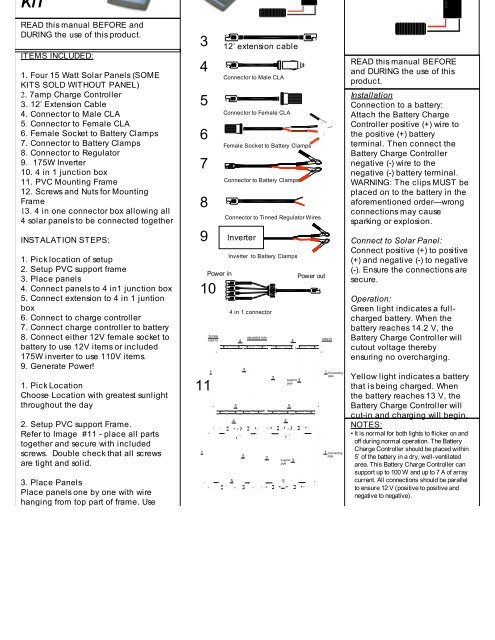
KIT<br />
READ this manual BEFORE and<br />
DURING the use of this product.<br />
ITEMS INCLUDED:<br />
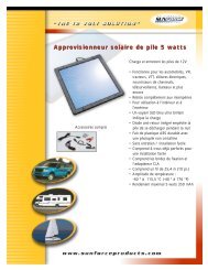
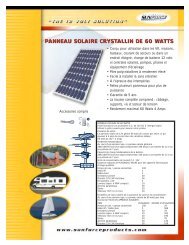
1. Four 15 Watt Solar Panels (SOME<br />
KITS SOLD WITHOUT PANEL)<br />
2. 7amp Charge Controller<br />
3. 12’ Extension Cable<br />
4. Connector to Male CLA<br />
5. Connector to Female CLA<br />
6. Female Socket to Battery Clamps<br />
7. Connector to Battery Clamps<br />
8. Connector to Regulator<br />
9. 175W Inverter<br />
10. 4 in 1 junction box<br />
11. PVC Mounting Frame<br />
12. Screws and Nuts for Mounting<br />
Frame<br />
13. 4 in one connector box allowing all<br />
4 solar panels to be connected together<br />
INSTALATION STEPS:<br />
1. Pick location of setup<br />
2. Setup PVC support frame<br />
3. Place panels<br />
4. Connect panels to 4 in1 junction box<br />
5. Connect extension to 4 in 1 juntion<br />
box<br />
6. Connect to charge controller<br />
7. Connect charge controller to battery<br />
8. Connect either 12V female socket to<br />
battery to use 12V items or included<br />
175W inverter to use 110V items.<br />
9. Generate Power!<br />
1. Pick Location<br />
Choose Location with greatest sunlight<br />
throughout the day<br />
2. Setup PVC support Frame.<br />
Refer to Image #11 - place all parts<br />
together and secure with included<br />
screws. Double check that all screws<br />
are tight and solid.<br />
3. Place Panels<br />
Place panels one by one with wire<br />
hanging from top part of frame. Use<br />
included screws to secure panels to<br />
frame<br />
4. Connect wires from panels to 4 in 1<br />
junction box – refer to image #10<br />
5. Connect extension to 4 in 1 juntion<br />
box<br />
Make sure connections are all tight.<br />
Image #3.<br />
6. Connect to charge controller<br />
Connect wire to end of extension cable<br />
See image #8. Refer to charge<br />
3<br />
4<br />
5<br />
6<br />
7<br />
8<br />
9<br />
1<br />
fix hole<br />
M5X70<br />
1<br />
11<br />
Power in<br />
10<br />
12’ extension cable<br />
Connector to Male CLA<br />
Connector to Female CLA<br />
Female Socket to Battery Clamps<br />
Connector to Battery Clamps<br />
Connector to Tinned Regulator Wires<br />
Inverter<br />
Inverter to Battery Clamps<br />
4 in 1 connector<br />
5<br />
4<br />
4<br />
3<br />
adjustable hole<br />
5 5<br />
USE OF INCLUDED ADAPTERS<br />
3<br />
2<br />
2<br />
4<br />
support 3<br />
pipe<br />
support 3<br />
pipe<br />
1. Connector to Male CLA<br />
Allows panels to be connected into female CLA<br />
of vehicle. Use of this connector should be<br />
done for very limited amounts of time due to<br />
lack of charge controller. Risk of overcharging<br />
battery is great.<br />
2. Connector to Female CLA<br />
Allows male CLA devices to be connected<br />
directly to panels. Since panels have variable<br />
voltage, use of this cable is limited.<br />
3. Female Socket to Battery Clamps<br />
5<br />
4<br />
Power out<br />
M5X70<br />
1 Connecting<br />
pipe<br />
1 Connecting<br />
pipe<br />
READ this manual BEFORE<br />
and DURING the use of this<br />
product.<br />
Installation<br />
Connection to a battery:<br />
Attach the Battery Charge<br />
Controller positive (+) wire to<br />
the positive (+) battery<br />
terminal. Then connect the<br />
Battery Charge Controller<br />
negative (-) wire to the<br />
negative (-) battery terminal.<br />
WARNING: The clips MUST be<br />
placed on to the battery in the<br />
aforementioned order—wrong<br />
connections may cause<br />
sparking or explosion.<br />
Connect to Solar Panel:<br />
Connect positive (+) to positive<br />
(+) and negative (-) to negative<br />
(-). Ensure the connections are<br />
secure.<br />
Operation:<br />
Green light indicates a fullcharged<br />
battery. When the<br />
battery reaches 14.2 V, the<br />
Battery Charge Controller will<br />
cutout voltage thereby<br />
ensuring no overcharging.<br />
Yellow light indicates a battery<br />
that is being charged. When<br />
the battery reaches 13 V, the<br />
Battery Charge Controller will<br />
cut-in and charging will begin.<br />
NOTES:<br />
• It is normal for both lights to flicker on and<br />
off during normal operation. The Battery<br />
Charge Controller should be placed within<br />
5’ of the battery in a dry, well-ventilated<br />
area. This Battery Charge Controller can<br />
support up to 100 W and up to 7 A of array<br />
current. All connections should be parallel<br />
to ensure 12 V (positive to positive and<br />
negative to negative).<br />
FAQ<br />
1. How many panels can I connect to my 7<br />
Amp Solar Charge Controller<br />
A. You can connect up to 105 Watts of Solar<br />
Power to the 7 Amp Solar Charge<br />
Controller. Panels should be connected<br />
in parallel – positive to positive, negative<br />
to negative.<br />
2. When will the Charging Indication light<br />
(green) light up<br />
A. The charging controller indication green<br />
light will light up when the battery voltage<br />
reaches 14.2 Volts and the SCC will<br />
prevent the solar panels from<br />
overcharging the battery. It is normal for
-Measure the panel voltage with a voltmeter.<br />
The voltage reading should be between 16 to<br />
FAQ 25 V in the sun.<br />
What types of batteries can this solar panel<br />
charge<br />
Any 12 V battery used in cars, boats, RV’s,<br />
motorcycles, etc.<br />
How can I run 120 V AC appliances with my<br />
Solar Power Panel<br />
Connect the battery to a power inverter that<br />
converts DC power to AC power.<br />
Can I overcharge my battery<br />
Yes, it is strongly recommended that a Battery<br />
Charge Controller<br />
Can I use this Solar Power Panel outdoors<br />
Yes, this Solar Power Panel has been<br />
weatherproofed. The weatherproofing<br />
includes UV protection and protects from<br />
weather effects of -35°F to 175°F.<br />
Can I extend the wire<br />
Without loss of power or voltage, the 12’ wire<br />
can be extended up to a maximum of 25’ with<br />
a 16-gauge wire. Ensure proper connections.<br />
Connect Voltmeter to each individual panel<br />
separately and observe Open Voltage. Open<br />
Voltage can range from 16 Volts to 24 Volts. Once<br />
all panels test for voltage, proceed to step B.<br />
B. Test Connection to Charge Controller for Voltage.<br />
Reconnect Solar Panels, and connect to charge<br />
controller as per instructions. Measure open circuit<br />
Voltage at the battery side of the charge controller.<br />
Open circuit voltage should read 5-10% lower than<br />
without charge controller. Open circuit<br />
measurement will read between 15 and 23.5.<br />
C. Connect charge controller to battery<br />
First, disconnect solar panels and connect charge<br />
controller to battery. Always connect charge<br />
controller to battery first and remove last. Observe<br />
polarity – positive to positive and negative to<br />
negative.<br />
D. Reconnect Solar Panels to Charge Controller.<br />
If battery voltage is 14.2 or higher, the GREEN light<br />
should be on. If battery voltage is between 13 and<br />
14.2, the YELLOW LED should be on.<br />
If battery voltage is 13 or lower, the YELLOW LED<br />
should be on.<br />
If all testing results within the above indicated<br />
ranges, solar system is in acceptable range. If<br />
Voltage reading indicate lower ranges, repeat<br />
above connections and retest. Finally, it is<br />
common to have 12V Battery issues such as dead<br />
cells or non-rechargeable battery problems.<br />
fix hole<br />
M5X70<br />
4<br />
adjustable hole<br />
4<br />
M5X70<br />
1<br />
3<br />
2<br />
support 3<br />
pipe<br />
1 Connecting<br />
pipe<br />
5 5<br />
4 4