User's manual 1
User's manual 1
User's manual 1

You also want an ePaper? Increase the reach of your titles
YUMPU automatically turns print PDFs into web optimized ePapers that Google loves.
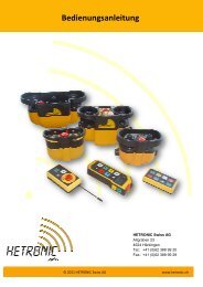
User’s Manual<br />
HETRONIC Swiss AG<br />
Altgraben 23<br />
4624 Härkingen<br />
Tel.: +41 (0)62 388 99 20<br />
Fax.: +41 (0)62 388 99 29<br />
1 © 2011 HETRONIC Swiss AG www.hetronic.ch
Using the Radio Control is forbidden for anybody who has not read and fully understood<br />
this <strong>manual</strong>. Special attention should be to given the safety instructions herein<br />
contained.<br />
All reproduction rights, either through photocopies or computer means or supports, are<br />
reserved. All texts, illustrations, and drawings are the propriety of HETRONIC and their use can<br />
only be granted prior to the formal permission of HETRONIC.<br />
The technical features of the Radio Control as described in this Manual may be subsequently<br />
modified without notice with the sole purpose of improving the equipment to better satisfy the<br />
user.<br />
2 © 2011 HETRONIC Swiss AG www.hetronic.ch
Table of Contents:<br />
1 SAFETY<br />
1.1 S a f e t y o f R a d i o C o n t r o l S y s t e m s<br />
1.2 S a f e t y I n f o r m a t i o n<br />
1.3 A u t h o r i z e d O p e r a t o r s<br />
1.4 S a f e t y M e a s u r e s t o b e t a k e n w i t h i n t h e w o r k i n g a r e a<br />
1.5 P r o t e c t i o n D e v i c e s<br />
1.6 H o w t o r e a c t a n d b e h a v e i n c a s e o f a n E m e r g e n c y<br />
2 OPERATION<br />
2.1 B a t t e r y Use<br />
2.2 T h e b a t t e r y c h a r g e r a n d r e - c h a r g e a b l e b a t t e r i e s<br />
2.3 C o n t r o l E l e m e n t s<br />
2.4 V i s u a l C h e ck<br />
2.5 S a f e t y C o n t r o l a n d S t a r t - u p o f t h e R a d i o C o n t r o l<br />
2.6 D i g i t a l F u n c t i o n a n d P r o p o r t i o n a l F u n c t i o n<br />
2.7 O p e r a t i n g p r o b l e m s<br />
2.8 T r o u b l e s h o o t i n g T a b l e<br />
2.9 T h e r a d i o t r a n s m i s s i o n a n d r e c e i v i n g s y s t e m<br />
3 INSTALLATION<br />
3.1 Po s i t i o n i n g t h e r e c e i v e r<br />
3.2 O u t s i d e e l e c t r i c a l c o n n e c t i o n s<br />
4 MAINTENENC<br />
5 DISPOSAL<br />
6 TECHINCAL DATA<br />
6.1 T h e t r a n s m i t t e r i n g e n e r a l<br />
6.2 T h e r e c e i v e r i n g e n e r a l<br />
7 MAP<br />
8 PRODUCT OVERVIEW<br />
3 © 2011 HETRONIC Swiss AG www.hetronic.ch
User’s <strong>manual</strong><br />
1 SAFETY<br />
1.1 Safety of the Radio Control System<br />
This Radio Control System has been fitted with electronic and mechanical safety devices.<br />
Processing control signals sent by other transmitters is impossible as the transmission codes<br />
are totally univocal.<br />
1.2 Safety Information<br />
The use of the Radio Control applied to any machinery allows the operator greater freedom of<br />
movement within the working area, improved handling accuracy whilst improving both the<br />
efficiency and the safety of the operator. However, all these benefits do require a certain<br />
attention from the operator and the staff in charge of maintenance.<br />
The correct and safe use of the Radio Control requires the operator to visually follow the<br />
remote-controlled machine.<br />
It is therefore compulsory that anyone using the transmitting unit stops the Radio Control and<br />
removes the starting key from the transmitting unit or the battery from its casing during the<br />
break times.<br />
The maintenance staff should check that the receiver unit is not powered during the control<br />
operations, the change of the battery or the periodic or extraordinary maintenance operations in<br />
general.<br />
Each Radio Control should be checked at least once a year. Any repair should be made at<br />
authorized centers or centers that either QUEST or HETRONIC have recommended or directly<br />
at the QUEST or HETRONIC service and spare parts center. Any use of non-original spare<br />
parts or tampering by non-authorized staff immediately cancels all the guarantee rights.<br />
1.3 Authorized Operators<br />
IMPORTANT !<br />
Always verify the operating instructions of your machine in order to be aware of any further<br />
important information to be observed. When placing the transmitter away during the breaks, the<br />
user must make sure that no unauthorized people can use it by turning the switch off or<br />
removing the key or the battery from its case and locking it in a safe place. In this way, any<br />
abusive operations by unauthorized third parties will be prevented. The user must be able to<br />
have access to all of the operating instructions that are necessary for the smooth operation of<br />
the machine to be controlled. The user must also read and be sure to have understood each<br />
section of this <strong>manual</strong> before<br />
using the Radio Control.<br />
1.4 Safety Measures to be taken within the working area<br />
The user should ensure that the working area in which the Radio Control will be used is free<br />
from any risks for the movement or other potential safety risks. For example, the user should<br />
verify that the working area is an area free from any obstacles or dangerous situations that<br />
could jeopardize the possibility of operating in total safety.<br />
4 © 2011 HETRONIC Swiss AG www.hetronic.ch
1.5 Protection Devices<br />
All of Hetronic’s Industrial Radio Controls have been fitted with an emergency stop push button<br />
on the control board of the transmitting unit.<br />
Some other protection devices exist in the Radio Control system which automatically intervene<br />
whenever:<br />
• There is a radio interference in the working area that affects the frequency range of the<br />
Hetronic<br />
Industrial Radio Control;<br />
• The action range of the transmitting unit is exceeded. In the event of the above the radio<br />
control immediately activates the Emergency Stop, and interrupts any outgoing signal of the<br />
receiving unit whilst maintaining continuous and constant radio contact between the transmitter<br />
and receiver.<br />
Some radio controls of the HH palm-held series manufactured for small applications have not<br />
been fitted with a real emergency stop push-button, unless regulations require it. However, a<br />
completely automatic emergency system interrupts the signals and sends the receiving unit into<br />
an emergency condition if the transmitter for longer than three seconds has carried out no<br />
operations. To quit the state of emergency any it is sufficient to carry out any man oeuvre of the<br />
transmitter.<br />
1.6 How to react and behave in case of an Emergency<br />
WARNING !<br />
In any Emergency situation, immediately push the Red Push Button EMERGENCY STOP<br />
(also called: EMERGENCY STOP PUSH). Then, follow the instructions in the machine<br />
operating <strong>manual</strong>.<br />
Unlock stop button by Push-Pull- Stop Momentary Stop<br />
Turning clockwise<br />
5 © 2011 HETRONIC Swiss AG www.hetronic.ch
2 OPERATION<br />
2.1 Battery Use<br />
The Hetronic Radio Control system is fitted with batteries for operating the transmitter.<br />
According to the type of Radio Control and the Customer’s request, the supply may include<br />
Alkaline batteries series mignon 1,5 VDC to be inserted in the specific support or, in most<br />
cases, rechargeable NiCd or NiMh batteries.<br />
WARNING !<br />
Never try to re-charge Alkaline batteries in a battery charger. Alkaline batteries cannot be<br />
recharged.<br />
The working voltage of the transmitter is constantly controlled. Should it fall below a certain<br />
value, an intermittent buzzer will be heard for about 30 seconds before the system automatically<br />
shuts down. Should the battery run down, apply the following procedure:<br />
ALKALINE MIGNON BATTERIES:<br />
Place the transmitter on a clean and dry surface. Remove the battery support from its casing on<br />
the transmitter by pushing towards the contact terminals and prizing outwards to then remove<br />
the run down batteries and replace them with new charged ones (according to the different<br />
types of Radio Controls, the support can house a maximum of 2 or 3 1,5 VDC alkaline stylus<br />
batteries. The HH systems include 2 batteries. To withdraw the support, push the black tab at<br />
the end of the battery casing downwards.<br />
WARNING !<br />
Use only Alkaline batteries. The voltage the zinc-carbon batteries provide is not sufficient<br />
because of their typical inner resistance.<br />
Now, replace the battery holder in the specific casing of the transmitter by pushing against the<br />
contact terminals until it fits perfectly.<br />
6 © 2011 HETRONIC Swiss AG www.hetronic.ch
2.2 The battery charge and re-chargeeable batteries<br />
Place the transmitter on a clean and dry surface. Remove the run down battery from its casing<br />
on the transmitter by pushing towards the contact terminals and prizing outwards to then<br />
remove the run down battery and replace it with the new charged one in the battery charger<br />
supplied (To remove the rechargeable battery from HH systems, the black tab at the end of the<br />
battery casing downwards). Put the replaced run down battery immediately under charge.<br />
Check that the battery charger is powered with the lighting up of the Led on the outside. During<br />
the recharging of the battery, the outer Led will remain on. It will start blinking as soon as the<br />
battery is charged. A sophisticated control system of the battery being charged means the<br />
battery under charge can be left for as long as desired. In the HH systems using the VersaPak<br />
battery charger, the battery must not be re-charged for more than 24 hours.<br />
WARNING !<br />
Use HETRONIC original spare parts only! If not, there is the danger of an explosion.<br />
Chemical substances that leak or parts that detach themselves can cause irreparable<br />
damage.<br />
7 © 2011 HETRONIC Swiss AG www.hetronic.ch
2.3 Control Elements<br />
Hetronic manufactures a very wide range of Industrial Radio Controls suitable for just as many<br />
applications. Furthermore, Industrial Radio Controls are manufactured according to the specific<br />
requests of the Customer or the User. Each radio control can be fitted with many different<br />
control elements according to the machine to be controlled, as well as provided with standard<br />
controls for its operation, stopping, acoustic warning, start switch, warning led etc… Push<br />
buttons, switches, selectors, joysticks and special control accessories complete the radio control<br />
and are features of each type. In most cases, the control elements of the Radio Control are<br />
arranged in exactly the same way as those on the normal control panel, the only difference<br />
being that a machine is started without a cable command.<br />
2.4 Visual Check<br />
WARNING !<br />
Always check the sound condition of the transmitter before operating.<br />
• Are all of the safety devices in the correct position and in good condition<br />
• Are there any broken parts<br />
• Are all of the rubber protections and the actuator covers sound<br />
• Are all of the connecting plugs and cables sound<br />
WARNING!<br />
Never work with a Radio Control with any of the above-mentioned damage!<br />
Always remove any above-mentioned faults before starting to work!<br />
2.5 Safety Control and Start-up of the Radio Control<br />
WARNING !<br />
Important checks on some of the functions mentioned below are required for the first<br />
start-up of the Radio Control!<br />
• Verify that the transmitter battery casing also houses a support with charged alkaline batteries<br />
or a charged rechargeable battery.<br />
• Release the Emergency Stop Push-button, if pressed.<br />
• Insert the starting key into the specific switch on the transmitter (stage to be skipped if of the<br />
HH and Mini palm-held radio control type)<br />
• Turn the starting key from position “0” to position “1” (stage to be skipped if of the HH and Mini<br />
palm-held radio control type).<br />
• Wait for the starting green led of the transmitter to start flashing regularly (stage to be skipped<br />
if of the HH and Mini palm-held radio control type).<br />
• Press the start button on the transmitter for at least one second (stage to be skipped if of the<br />
HH and Mini palm-held radio control type).<br />
• Now, your Radio Control is ready to work. Start any function of the transmitter and verify<br />
whether the machine stops when the same function is released should you release it or re-set it<br />
to zero.<br />
• Now check that the Emergency Stop function works exactly as described by the manufacturer<br />
of the machine<br />
by applying the following procedure:<br />
1. Start any of the functions of the transmitter and keep it running<br />
2. Push the Emergency push button on the transmitter<br />
3. Verify that the function carried out stops immediately and that no other functions can be then<br />
operated from the transmitter<br />
8 © 2011 HETRONIC Swiss AG www.hetronic.ch
4. Was the safety control successful and does the Emergency Stop function work perfectly<br />
5. Now release all the control elements<br />
6. Release the Emergency Stop push button, your Radio control is now ready to operate in total<br />
safety<br />
WARNING !<br />
Turn the machine off immediately should any fault or problem be noticed during the<br />
initial starting. Never operate the machine unless the Emergency Stop Button functions<br />
properly.<br />
Serious danger exists for both people and things from the non-observance of this<br />
extremely important regulation. Any operation not conforming to this basic operating<br />
rule may lead to the loss of both the operating permit and your guarantee.<br />
2.6 Digital Functions and Proportional Functions<br />
Two possible types of electronic control exist that can be operated from the Radio Control, the<br />
digital and analogical also called ON-OFF and Proportional respectively. The ON-OFF control<br />
determines either the opening or the closing of a relay within the receiver when the transmitter<br />
activates this control. Usually, these are commands that can be sent from push-buttons,<br />
switches, selectors or digital joysticks. The Proportional control is a function determining a<br />
variable output in either current or voltage in a directly proportional way to the varying of the<br />
position of an analogical actuator on the transmitter, be it a potentiometric joystick or a simple<br />
potentiometer. Hetronic manufactures different types of proportional controls to control several<br />
models of solenoid valves, inverters or servo controls. The signal transmission technology<br />
remains unchanged, while the proportional output module of the receiver is adequate for the<br />
different requirements of the command to be carried out.<br />
2.7 Operating problems<br />
Repairs and checks following failure of the radio control equipment must be carried out<br />
according to the instructions below so that the system maintains all of its original features. In the<br />
event of non-operation, check that the machine provided with radio control runs smoothly with<br />
traditional control systems such as, for example, cable control, fixed control panel etc… Verify<br />
that in the area your are operating in with your Radio Control no other radio equipment has<br />
started working and is operating on the same radio frequency. If the relays and the proportional<br />
modules of the receiver are not energized when commands have been transmitted and the<br />
machine therefore cannot carry out any operation, then check the conditions of the receiver<br />
feeding fuse. Also check the wiring connections on the receiver terminal board as well as on the<br />
multiple plug while checking that no wires have become disconnected from their housing or<br />
coupling. The non-operation of the Radio Control system can depend on either the transmitter<br />
or the receiver. A table has therefore been drawn up in the following paragraph to make a swift<br />
diagnosis of the most common failures or malfunctions.<br />
2.8 Troubleshooting Table<br />
Your Radio Control has been manufactured using the most advanced microprocessor<br />
technology and built with the utmost care and accuracy. Each system is subject to a strict<br />
quality assurance test at the manufacturer’s before being delivered to the customer. However,<br />
should a failure subsequently occur, a swift diagnosis is possible and hence a quick reset of the<br />
Radio Control. This is possible also thanks to the modern modular system used in the Hetronic<br />
systems. Table follows:<br />
9 © 2011 HETRONIC Swiss AG www.hetronic.ch
WARNING !<br />
In case of a failure, please check the following points before calling the Hetronic service<br />
center.<br />
Tabelle zur Identifizierung von Störungen bei Auftreten von Mängeln<br />
2.9 Funkübertragung- und Empfang<br />
The Hetronic Radio Control allows for the operating machines to be controlled in general by<br />
means of electro-magnetic waves. It is made up of a portable transmitter held by the operator<br />
and of a receiver that may be either fixed or mobile and that is usually installed on the machines<br />
to be commanded. Each function originated from several devices or control actuators of the<br />
transmitter is transformed into a serial command that is coded and transmitted through a highfrequency<br />
carrier. The receiver captures the information output from the transmitter, deciphers it<br />
and sends the controls to the machine by means of relays, power transistors or proportional<br />
electronic cards, by cable and multiple plug. The information sent from the transmitter is<br />
contained in a telegram. This telegram consists of an address and a control code. The address,<br />
or matching code, contains the identification elements to match the transmitter with the receiver.<br />
The command code contains all of the information relevant to the commands that the machine<br />
should carry out.<br />
10 © 2011 HETRONIC Swiss AG www.hetronic.ch
3 INSTALLATION<br />
WARNING !<br />
• Only a qualified and specialized technician should install the receiver of a radio control<br />
to the electrical system of a machine (see item 4, Maintenance) who is acquainted with<br />
both the electrical circuit of the machine and the radio control technical features.<br />
• During the entire installation stage both the transmitter and the receiver must be turned<br />
off.<br />
• All of the regulations on the health of the staff working within the installation area,<br />
together with any local regulations in force, and those on fire prevention must be<br />
observed.<br />
• HETRONIC deny all responsibility; neither does it grant any guarantee whatsoever for<br />
any damage caused to things or persons due to the improper or careless use of this<br />
equipment or due to the non-observance of any regulation or that, which has been<br />
indicated in the operating instructions.<br />
3.1 Positioning the receiver<br />
For the Radio Control to operate smoothly, it is necessary that the receiver should be installed<br />
in such a position as to allow the maximum reception of radio waves from the antenna. The<br />
metallic parts of the machine to be controlled that surround the receiver create a barrier that<br />
interferes with reception.<br />
Sometimes, however, in extreme cases and if the space is inadequate, installation needs to be<br />
carried out inside the electrical boards or in areas of the machine that are not ideal for good<br />
radio reception. Should this kind of installation be necessary, then the equipment must be<br />
provided with an additional outside antenna. Your supplier will be able to supply further detailed<br />
information and specific items for the outside antennas suitable for this use.<br />
In most cases, the receiver can be housed on any side of the machine or, if necessary, for<br />
installations on vehicles even inside the glass cabin. It is also necessary to place the receiver<br />
where it is accessible and safe to work both for those who carry out the installation of the<br />
electrical connections and for those who will do the future maintenance. In any case, the<br />
receiver must be installed in such a manner that any possible connectors or cable pressers face<br />
downwards.<br />
Should such an installation be performed on board mobile machinery or on a vehicle, then you<br />
should attach four rubber bumpers that can be ordered directly from your Hetronic dealer,<br />
unless already supplied as standard fittings on the radio control type in use. These rubber<br />
bumpers will prevent strong vibrations from the machine to the receiver.<br />
11 © 2011 HETRONIC Swiss AG www.hetronic.ch
Zeichnung der Empfangseinheit<br />
WARNING !<br />
When positioning the receiver, check that the outside antenna is not being screened by<br />
large metallic surfaces. This should also be taken into consideration when the antenna of<br />
the receiver is inside the said receiver.<br />
12 © 2011 HETRONIC Swiss AG www.hetronic.ch
3.2 Outside electrical connections<br />
It is necessary to install a switch on the machine to be controlled that allows the power from the<br />
radio control receiver to be cut off whenever needed.<br />
A relay, a transistor or a proportional card in the receiver corresponds to each command<br />
inserted in the transmitter.<br />
The same radio control can be installed on several models of machinery or vehicles with very<br />
different connection configurations characterizing the auxiliary control circuit on the machine.<br />
To facilitate this and to allow different connecting patterns, each contact of the output terminal<br />
board is independent and isolated from the others.<br />
13 © 2011 HETRONIC Swiss AG www.hetronic.ch
4 MAINTENANCE<br />
The Hetronic Radio Control system does not require any special maintenance. However, some<br />
precautions are necessary in order to ensure that the equipment is both efficient and safe. Each<br />
radio control must be checked at least once a year. The staff in charge of maintenance must<br />
check that the receiver is not on during the checks and the inspection inside the transmitter.<br />
Dust and other material from the working environment as well as dirt can deposit on the<br />
transmitter. Remove it so that the buttons, joysticks and actuators in general, including the<br />
emergency stop push button, the start button and the starting key selector are always clean and<br />
therefore in good working order.<br />
Each control unit has been designed so that all that the above causes the least amount of<br />
problems possible to the smooth operation of the Radio Control. However, careful periodical<br />
maintenance by the user will certainly prolong its life span. The inner inspection of the<br />
transmitter should be carried out in a dry and damp-free place. As well as removing all traces of<br />
dirt that may have got inside, and drying any condensation with warm air, the checking of the<br />
connections of the different wires and terminal boards of interconnections, as well as the clean<br />
condition of the electrical contacts of all of the control actuators is also highly recommended.<br />
WARNING !<br />
In the event of the possible oxidation of the electrical contacts, never use any type of<br />
anti-oxidant spray or similar product. Instead, contact the nearest service center to<br />
immediately replace these parts. These problems can be caused by the particular<br />
environmental conditions in which the radio control operates. Using chemical products<br />
on the actuators will provoke irreparable damage to the mechanical and electronic inner<br />
parts.<br />
The duration and the capacity of the batteries depend on many elements such as the operating<br />
temperature, the charging and discharging cycles, but basically on how often the radio control is<br />
used. It is highly recommended to always use the battery charge to the very maximum extent<br />
and to replace it at least every 2 years.<br />
Besides the regular checks on the interconnections and the firm tightening of the terminal<br />
boards for the output controls, it is recommended to check that the seal of the transmitter unit<br />
cover is in good condition and that it is watertight. After 2/3 years of operation, it is suggested to<br />
check the smooth operation of relays, transistors, and proportional electronic boards, their<br />
command responses and their drop out speed. Such a check is made easier by the signaling<br />
LED's for each control. Special layers of resin-based insulating paint and with anti-oxidant<br />
properties protect the electronic parts of the Radio Control system; hence they do not require<br />
any maintenance. It is, however, necessary to check the various interconnection connectors<br />
between the different modules<br />
5 DISPOSAL<br />
WARNING!<br />
Avoid environmental pollution!<br />
Electrical devices and their parts are dangerous waste. This specially applies to batteries and<br />
rechargeable accumulators. Engage a specialized company for their disposal.<br />
14 © 2011 HETRONIC Swiss AG www.hetronic.ch
6 TECHNICAL DATA<br />
6.1 The transmitter in general<br />
Possible transmission channels:<br />
Radio output power:<br />
Antenna:<br />
Supply voltage:<br />
Battery type:<br />
Working frequency in MHz: from 433,100 to<br />
434,750 or from 458,525 to 459,175 MHz<br />
With 25 KHz channel pitch<br />
32 in <strong>manual</strong> or automatic mode<br />
Protection level:<br />
Active Emergency feedback time:<br />
Passive Emergency feedback time:<br />
IP 65 (HH/2 and HH/5 IP not suitable for<br />
outside use)<br />
7 MAP<br />
Altgraben 23, 4624 Härkingen<br />
17 © 2011 HETRONIC Swiss AG www.hetronic.ch
8 PRODUCT OVERVIEW<br />
18 © 2011 HETRONIC Swiss AG www.hetronic.ch
HETRONIC Swiss AG<br />
Altgraben 23<br />
4624 Härkingen<br />
Tel.: 062 388 99 20<br />
Fax.: 062 388 99 29<br />
info@hetronic.ch<br />
www.hetronic.ch<br />
19 © 2011 HETRONIC Swiss AG www.hetronic.ch