Shallow Junction Formation with Preamorphization and Rapid ... - LSI
Shallow Junction Formation with Preamorphization and Rapid ... - LSI
Shallow Junction Formation with Preamorphization and Rapid ... - LSI

Create successful ePaper yourself
Turn your PDF publications into a flip-book with our unique Google optimized e-Paper software.
the target mainly by electron collisions, causing less<br />
damage to the crystalline lattice. In this process, point<br />
defect clusters are generated along the collision cascade.<br />
Thermal annealing dissolute these clusters, producing a<br />
supersaturation of self-interstitials. The excess<br />
interstitials kick dopants out of substitutional locations to<br />
form mobile dopant-interstitial complexes that broaden<br />
the doping profile, the so-called transient enhanced<br />
diffusion. So, rapid thermal annealing alone, couldn’t<br />
avoid boron diffusion.<br />
Boron concentration(cm -3 )<br />
10 20 a<br />
10 19<br />
10 18<br />
10 17<br />
10 16<br />
as-implanted<br />
RTP 960 o C/30s<br />
10 15<br />
0 50 100 150 200 250 300 350<br />
10 20<br />
10 19<br />
b<br />
#1<br />
10 18<br />
10 17<br />
10 16<br />
10 15<br />
0 50 100 150 200 250 300 350<br />
10 20<br />
10 19<br />
c<br />
10 18<br />
#2<br />
10 17<br />
10 16<br />
10 15<br />
0 50 100 150 200 250 300 350<br />
10 20 d<br />
10 19<br />
#3<br />
10 18<br />
10 17<br />
10 16<br />
10 15<br />
0 50 100 150 200 250 300 350<br />
depth(nm)<br />
#0<br />
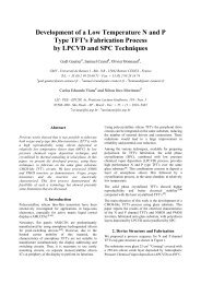
Fig. 1: SIMS profiles of B, as-implanted <strong>and</strong> after<br />
rapid thermal annealing 960 o C/30s. a)no<br />
preamorphization, b)preamorphization <strong>with</strong> argon,<br />
c)preamorphization <strong>with</strong> Si, d)preamorphization<br />
<strong>with</strong> F. All boron implants were done at 10 keV.<br />
Figure 1-b shows the profiles for Ar preamorphized<br />
sample. Compared to fig. 1-a, as-implanted profile<br />
shows that preamorphization reduced the channeling<br />
effect, but after annealing, diffusion shows up, <strong>and</strong> the<br />
previous advantage was lost. Previous work <strong>with</strong><br />
gettering mechanisms [5] showed that high dose Ar<br />
implants produce Si-interstitials that enhances boron<br />
diffusion. Fig. 1-c shows that preamorphization <strong>with</strong> Si<br />
was slightly less effective to avoid channeling than Ar,<br />
due to its lower mass, but the annealed profile shows that<br />
diffusion was supressed <strong>with</strong> rapid thermal annealing.<br />
Fluorine preamorphization (fig. 1-d) had a more<br />
noticeable effect. In addition to channeling supression in<br />
the as-implanted profile, the annealed sampled produced<br />
a very shallow (50 nm) boron profile, smaller than the<br />
as-implanted one. The expected result was a depth<br />
profile at least the same as before annealing, as we<br />
observed in Si preamorphization. Boron diffusion<br />
suppression was explained [3] by the interaction of<br />
excess F ions <strong>with</strong> interstitial Si, that otherwise are<br />
responsible for the enhanced diffusion. Probably, the<br />
formation of thermodynamically stable SiF x complexes,<br />
would immobilize this interstitials. However, we don't<br />
have a conclusive answer to the boron profile shrinkage.<br />
It is thought that a high vacancy-type defects<br />
concentration at the under-surface would be responsible<br />
for this effect, capturing boron ions. One experimental<br />
evidence [6] of a vacancy-rich region is that F <strong>and</strong> Cl<br />
ions implanted in Si, increase the oxidation rate <strong>and</strong><br />
suppress the formation of stacking fault defects,<br />
increasing vacancy-type defects. Although unexpected,<br />
junction shrinkage after thermal annealing already was<br />
observed in Mg-implanted GaAs [7]. This “uphill<br />
diffusion”, was explained by the substitutionalinterstitial<br />
diffusion mechanism. In the region of uphill<br />
diffusion, the dopants diffuse from areas of excess<br />
interstitials toward areas of excess vacancies. So, this<br />
model could be a reasonable explanation of the observed<br />
junction shrinkage.<br />
Table 2: Measured sheet resistance<br />
sample R S (Ω/sq)<br />
RTP 960 o C/10s<br />
R S (Ω/sq)<br />
RTP 960 o C/30s<br />
#0 (B) 589 335<br />
#1 (Ar+B) 426 335<br />
#2 (Si+B) 303 303<br />
#3 (F+B) 272 253<br />
Sheet resistance for all samples, table 2, were measured<br />
in a four-probe setup. 10 seconds treatment was not<br />
enough to complete activation on sample #0(direct B<br />
implant), but as shown before, increasing the time causes<br />
excess diffusion. The same occurs <strong>with</strong> the argon<br />
implanted sample #1. Sample #2, <strong>with</strong> Si pre-implant,<br />
had the same sheet resistance for both treatments,<br />
indicating that it needs less time to get higher electrical<br />
activation. This result is in agreement <strong>with</strong> X-ray<br />
diffraction measurements that showed a complete<br />
recrystallization after 10 seconds annealing.<br />
Unfortunately, due to a lack of time, we don’t have the