A 4 GHz Dual Modulus Divider-by 32/33 Prescaler in ... - LSI - USP
A 4 GHz Dual Modulus Divider-by 32/33 Prescaler in ... - LSI - USP
A 4 GHz Dual Modulus Divider-by 32/33 Prescaler in ... - LSI - USP
- No tags were found...

You also want an ePaper? Increase the reach of your titles
YUMPU automatically turns print PDFs into web optimized ePapers that Google loves.
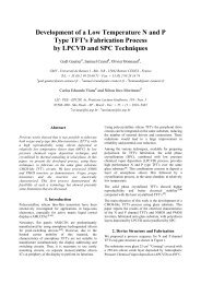
A 4 <strong>GHz</strong> <strong>Dual</strong> <strong>Modulus</strong> <strong>Divider</strong>-<strong>by</strong> <strong>32</strong>/<strong>33</strong> <strong>Prescaler</strong> <strong>in</strong> 0.35µmCMOS TechnologyFernando P. H. de MirandaEscola PolitécnicaUniversidade de São Paulo - BrasilAv. Prof. Luciano Gualberto, 158.Trav.3 CEP: 05508-900São Paulo - SP - Brasil.(55)(11) 3091 9721nando@lsi.usp.brJoão Navarro S.Jr.Escola PolitécnicaUniversidade de São Paulo - BrasilAv. Prof. Luciano Gualberto, 158.Trav.3 CEP: 05508-900São Paulo - SP - Brasil.(55)(11) 3091 5663navarro@lsi.usp.brWilhelmus A.M. Van NoijeEscola PolitécnicaUniversidade de São Paulo - BrasilAv. Prof. Luciano Gualberto, 158.Trav.3 CEP: 05508-900São Paulo - SP - Brasil.(55)(11) 3091 5668noije@lsi.usp.brABSTRACTThe design of a dual modulus prescaler <strong>32</strong>/<strong>33</strong> <strong>in</strong> a 0.35µm CMOStechnology is presented. The prescaler is a circuit employed <strong>in</strong>high frequency synthesizer designs. In the proposed circuit thetechnique called Extended True S<strong>in</strong>gle Phase Clock (E-TSPC), anextension of the True S<strong>in</strong>gle Phase Clock (TSPC) technique, wasapplied. Additionally some new structures to double the dataoutput rate are also employed. Simulations, based on the prescalerlayout, were carried out and the results <strong>in</strong>dicate that the circuitcan reach up to 4 <strong>GHz</strong> with 4.38 mW of power consumption andpower supply of 3.3 V.Categories and Subject DescriptorsB.7.0 [Integrated Circuits]: General.General TermsDesign.Keywords<strong>Prescaler</strong>, TSPC, High Speed Digital Circuit, Low Power1. INTRODUCTIONThe CMOS Technology has been the ma<strong>in</strong> <strong>in</strong>tegrated circuittechnology for at least 15 years due to its advantages <strong>in</strong> terms of<strong>in</strong>tegration level, power consumption, eas<strong>in</strong>ess of design, and lowcosts. With the cont<strong>in</strong>uous reduction of the transistor dimensions,some of these advantages, such as <strong>in</strong>tegration level, have<strong>in</strong>creased and new ones have been added, such as the technologyspeed, extend<strong>in</strong>g the technology uses to areas where only fasterand more expensive technologies (Bipolar and GaAs) wereapplicable.Permission to make digital or hard copies of all or part of this work forpersonal or classroom use is granted without fee provided that copies arenot made or distributed for profit or commercial advantage and thatcopies bear this notice and the full citation on the first page. To copyotherwise, or republish, to post on servers or to redistribute to lists,requires prior specific permission and/or a fee.SBCCI’04, Sept. 7-11, 2004, Porto de Gal<strong>in</strong>has, Pernanbuco, Brazil.Copyright 2004 ACM 1-58113-000-0/00/0004…$5.00.One of these new application areas is RF circuits: circuits fortransmission and reception of <strong>in</strong>formation through radiofrequency waves. This area presents wide spectrum ofapplications vary<strong>in</strong>g from command devices for automatic gatesto sophisticate cellular phones.In the more complex RF systems, an important block is thefrequency synthesizer. This block is responsible for the generationof signals <strong>in</strong> specific frequencies that are used for channelmodulation and demodulation <strong>in</strong>side the transmission band [1]. Asynthesizer is composed of a voltage controlled oscillator (VCO),counters, phase comparators, and filters. Some architectures ofsynthesizer use, with the counters, a dual-modulus prescalerN/N+1: a frequency divider that can divide an <strong>in</strong>put clock <strong>by</strong> N orN+1. In general the prescaler is a block with critical operation <strong>in</strong>terms of speed and power consumption s<strong>in</strong>ce it receives the clockdirectly from the VCO output, the fastest signal <strong>in</strong> the synthesizer.In this work, we will present the design and simulation results of adual-modulus prescaler <strong>32</strong>/<strong>33</strong>. In the prescaler was used the E-TSPC technique, Extended True S<strong>in</strong>gle Phase Clock, that uses theTrue S<strong>in</strong>gle Phase Clock (TSPC, a logic technique that workswith one clock phase [2]), and enlarges the acceptable designblocks and their possibility of connections [3], [4], [5].Additionally, we applied some new structures that are conceivedto duplicate the circuit speed [6]. The design was developed us<strong>in</strong>gthe AMS 0.35 µm CMOS technology, with four levels of metaland two of polysilicon. The paper is organized <strong>in</strong> five sections: <strong>in</strong>section two the E-TSPC technique and the new structures arepresented; <strong>in</strong> section three the prescaler <strong>32</strong>/<strong>33</strong> is discussed; <strong>in</strong>section four the results are drawn; <strong>in</strong> section five the conclusionsare summarized.2. THE E-TSPC TECHNIQUEThe E-TSPC technique, an extension of the TSPC, was proposed<strong>in</strong> [4]. A simplified presentation, with respect to the theorems andtheir demonstrations, is done <strong>in</strong> [3], and it serves as basis to whatis exposed here.The follow<strong>in</strong>g blocks are used for this technique:• complementary static logic gates CMOS;• dynamic, n-dynamic and p-dynamic, logic gates;• latches, n-latches and p-latches.
Also N-MOS like blocks [5] can be used (see Figure 1). Theseblocks can be built start<strong>in</strong>g from dynamic gates, n and p, or fromlatches, n and p. These blocks are faster although have higherpower consumption, and they should be used when high speed isnecessary.In the technique the concept of data cha<strong>in</strong>s [6], n-data cha<strong>in</strong>s andp-data cha<strong>in</strong>s also is <strong>in</strong>troduced. An n-data cha<strong>in</strong> is a portion ofthe circuit that evaluates the <strong>in</strong>put signals when the clock is at theHIGH level, and that holds the output value, with the lastevaluated state, when the clock is at LOW level. The later state iscalled hold<strong>in</strong>g state and the former, evaluation state. In the case ofp-data cha<strong>in</strong>s occurs the <strong>in</strong>verse of the n-data cha<strong>in</strong>s, be<strong>in</strong>g nowthe evaluation executed at the clock LOW level and the hold<strong>in</strong>g,at the HIGH level.Formally we can def<strong>in</strong>e n-data cha<strong>in</strong> as a data propagation pathwith the follow<strong>in</strong>g characteristics:1. must conta<strong>in</strong> at least one n-dynamic block or n-latch;2. must start <strong>in</strong> an external <strong>in</strong>put of the circuit or <strong>in</strong> the output ofsome p-dynamic block or p-latch;3. must conta<strong>in</strong> only static, n-dynamic, or n-latches blocks;4. do not matter the order or the number of these blocks;5. must f<strong>in</strong>ish <strong>in</strong> the <strong>in</strong>put of a p-dynamic block, or a p-latch, orbe a circuit output.<strong>in</strong>putclockclockn-transis.logica) n-dynamicoutput<strong>in</strong>putclockn-transis.logicoutputb) NMOS liken-dynamic<strong>in</strong>putclockclockp-transis.logicoutputc) p-dynamic<strong>in</strong>putclockp-transis.logicoutputd) NMOS likep-dynamicblocks B A , B C , B E and B I ; other n-data cha<strong>in</strong> is <strong>in</strong>itiated at the<strong>in</strong>put i d and follows through the blocks B C , B E , B F , B H and B K .Some special data cha<strong>in</strong>s of the E-TSPC will be used to doublethe circuit speed. These data cha<strong>in</strong>s are called fo structures. Tounderstand how they can be used, we must observe an operationcharacteristic of certa<strong>in</strong> data cha<strong>in</strong>s [6]. Consider data cha<strong>in</strong>s, n orp, that possess a s<strong>in</strong>gle latch (it must be, due to the rules, the lastblock of the data cha<strong>in</strong>). For these data cha<strong>in</strong>s, called as fo-datacha<strong>in</strong>s (data cha<strong>in</strong>s with the fusible outputs), the output stays <strong>in</strong> ahigh impedance state dur<strong>in</strong>g the hold<strong>in</strong>g state.Table 1. Rule of the block connections <strong>in</strong>side of data-cha<strong>in</strong>s.N-MOS like blocks must obey the same rules of the normal<strong>in</strong>put signalof the datacha<strong>in</strong>latchoutputn-dynamicoutputp-dynamicoutputlatch<strong>in</strong>putblocksn-dynamic<strong>in</strong>putp-dynamic<strong>in</strong>putn.r. n.r. n.r.n.r. n.a. n.a.n.r. odd n.a.n.r. n.a. oddn.r.: no restrictions; n.a.: the connection is not allowed; odd:an odd number of blocks is required.<strong>in</strong> p u tclockp-transis.logicn-transis.logice) n-la tchoutput<strong>in</strong>putp-transis.logicoutputclockf) N M O S liken-la tch<strong>in</strong>putclockp-transis.logicn-transis.logicg) p-la tchoutput<strong>in</strong> p u tclockn-transis.logicoutputh) NMOS likep-la tchFigure 1. Conversion of blocks to N-MOS like.In the case of p-data cha<strong>in</strong>s, a similar def<strong>in</strong>ition can be applied,chang<strong>in</strong>g n for p and vice versa.For the correct operation of a data-cha<strong>in</strong>, to make the evaluation<strong>in</strong> one clock phase and the hold<strong>in</strong>g <strong>in</strong> the other, it is necessary thatthe data cha<strong>in</strong> presents one of these two configurations:• at least two blocks, one dynamic block and one latch;• at least two latches and an even number of blocks (<strong>in</strong>versions)between them.Additionally, the adjacent blocks <strong>in</strong> the propagation path of adata-cha<strong>in</strong> need to have a number of blocks (<strong>in</strong>version) <strong>in</strong>accordance with the rules of table 1 (two blocks are calledadjacent if between them there are placed only static blocks).Examples of n-data cha<strong>in</strong>s are shown <strong>in</strong> Figure 2 [5] [6]: one n-data cha<strong>in</strong> is <strong>in</strong>itiated at the i a <strong>in</strong>put and follows through theFigure 2. Examples of n-data cha<strong>in</strong>s.This high impedance state <strong>in</strong> fo-data cha<strong>in</strong>s can be used to<strong>in</strong>crease the process<strong>in</strong>g speed, and implementations based on thatare proposed. The outputs of two fo-data cha<strong>in</strong>s, a p and an n,can be jo<strong>in</strong>ed and, <strong>in</strong> this case, we can get new processed signalsto each half cycle of the clock, what implies <strong>in</strong> doubl<strong>in</strong>g the dataoutput speed. Consider, for example, the circuit of Figure 3;dur<strong>in</strong>g the phase where clock is HIGH, the n-data cha<strong>in</strong> is <strong>in</strong> theevaluation state and imposes the result at the output, while the p-data cha<strong>in</strong> will be <strong>in</strong> high impedance state; dur<strong>in</strong>g the phasewhere the clock is LOW, the p-data cha<strong>in</strong> is <strong>in</strong> evaluation andimposes the result at the output, while the n-data cha<strong>in</strong> will be <strong>in</strong>high impedance. This type of structure is used <strong>in</strong> the proposedcircuit.
Figure 3. Fo Structures to duplicate the output data rate.3. CIRCUIT DUAL-MODUL<strong>USP</strong>RESCALER <strong>32</strong>/<strong>33</strong>Figure 4 presents a conventional dual-modulus prescaler <strong>32</strong>/<strong>33</strong>circuit. It receives a clock signal and divides <strong>by</strong> <strong>32</strong> or <strong>33</strong>,depend<strong>in</strong>g on the value of an external control signal called S M :when S M is at LOW logic level, the circuit divides the clock <strong>by</strong> <strong>32</strong>(N); when S M is at HIGH logic level, it divides the clock <strong>by</strong> <strong>33</strong>(N+1). This circuit is composed of two counters, a synchronouscounter and an asynchronous counter. In the crosshatched part wef<strong>in</strong>d the synchronous counter that carries out the count<strong>in</strong>g up to 4or 5, depend<strong>in</strong>g on the value of the signal div8. The synchronouscounter constitutes the critical element for good performance <strong>in</strong>terms of speed, s<strong>in</strong>ce it receives as its clock the signal from theVCO output and, thus, works <strong>in</strong> the highest speed of the system.The asynchronous part is composed of three D type flip-flops (D-FF) that carry out the count<strong>in</strong>g up to 8. It is the synchronouscounter that generates the clock for the first D-FF of theasynchronous counter.clock<strong>in</strong>1<strong>in</strong>2DD-FF QD QD-FFC Qp-datacha<strong>in</strong>p-datacha<strong>in</strong>fo-n datacha<strong>in</strong>n-datacha<strong>in</strong>fo-p datacha<strong>in</strong><strong>Divider</strong> <strong>by</strong> 4/5 (counter)smDD-FFD QD-FFC QQdiv8Figure 4. The <strong>Dual</strong>-<strong>Modulus</strong> <strong>Prescaler</strong> schematic (divider <strong>by</strong><strong>32</strong>/<strong>33</strong>).The implementation proposed here for the prescaler is based on anew synchronous counter circuit. This circuit is <strong>in</strong> fact a statemach<strong>in</strong>e and, similar to any state mach<strong>in</strong>e, it can be implementedwith the fo-data cha<strong>in</strong>s previously def<strong>in</strong>ed. The desired output ofthe circuit, the clock divided <strong>by</strong> 4 or 5, is the state mach<strong>in</strong>e outputand will be produced <strong>by</strong> the comb<strong>in</strong>ation of two other signals,which are generated with a rate equal to the half of the clock rate.The new implemented synchronous counter works as the statemach<strong>in</strong>e whose diagram is <strong>in</strong> figure 5, and its clock, clk/2, has afrequency equal to the half of the orig<strong>in</strong>al clock frequency (theclock that we desire to divide <strong>by</strong> 4 or 5). The output is formedfrom the comb<strong>in</strong>ation of signals A and B: A dur<strong>in</strong>g the phasewhere clk/2 is HIGH and B dur<strong>in</strong>g the phase where clk/2 is LOW.We can exemplify the operation analyz<strong>in</strong>g the state diagram offigure 5. When the logic value at the div8 (division control signal)is HIGH, there are two possible operations for the state mach<strong>in</strong>e:to be mov<strong>in</strong>g between states 000 and 110, or between 100 and010. Let us consider the case of mov<strong>in</strong>g between 000 and 110.The output signal will have the values LOW, A, LOW, B, HIGH,A, and HIGH, B (0011) dur<strong>in</strong>g each half cycle of the clk/2. If weremember that the circuit works with half of the orig<strong>in</strong>al clockoutDD-FFD QD-FFC QQoutput<strong>32</strong>/<strong>33</strong>signal rate, we can see that the AB comb<strong>in</strong>ation is the orig<strong>in</strong>alclock signal divided <strong>by</strong> 4. When the logical value <strong>in</strong> div8 is LOW,the states will pass through the follow<strong>in</strong>g states: 000, 110, 001,010 and 101 and the output will have the values LOW, A, LOW,B, HIGH, A, HIGH, B, LOW, A, LOW, B, LOW, A, HIGH, B,HIGH, A, and LOW, B, (0011000110), dur<strong>in</strong>g each half cycle ofthe clk/2. In this case we can see that AB comb<strong>in</strong>ation is the clocksignal divided <strong>by</strong> 5.Operation ofthe divider<strong>by</strong> 4Operation of thedivider <strong>by</strong> 5Clock signalCounteroutputOUCounteroutputs<strong>in</strong>al div8Counteroutputsignal div8signal ATemporarystate 0001011 111011100001 101100signal A e Bsignal Bany valuesignal Bany valueStateABC1010<strong>in</strong>put div8clock/2 signal = state mach<strong>in</strong>e clocksignal AFigure 5. State diagram of the circuit.Figure 6 presents the schematic diagram of the state mach<strong>in</strong>e thatimplements the Figure 5 state diagram, and Figure 7 presents thetransistor diagram of the complete synchronous counter for theAMS 0.35 µm technology (the transistor dimensions are also<strong>in</strong>dicated). For the circuit implementation, TSPC D-FFs [2](similar to Figure 8 D-FFs) modified <strong>in</strong> accordance with the E-TSPC rules have been applied. The logic gates NOR and ANDhave been merged with D-FFs, form<strong>in</strong>g the three blocks marked<strong>in</strong> the Figure 7 (BL A , BL B and BL C ). In addition to these blocks,we have two more, BL O1 and BL O2 , that are responsible formerg<strong>in</strong>g the A and B signals.State Mach<strong>in</strong>eclk/2DD-FFQADD-FFBL A div8 BL C BL BFigure 6. Schematic diagram for implementation of the statemach<strong>in</strong>e of the figure 5.In the asynchronous counter configuration TSPC D-FFs (Figure8) were used. This counter presents a less critical operation <strong>in</strong>terms of speed.Some comments must be done regard<strong>in</strong>g the circuit transistordimensions:QC0DD-FFQB
• <strong>in</strong> most transistors, the m<strong>in</strong>imum width value allowed <strong>in</strong> thetechnology, W=1µm, was used. With this choice we favor a lowpower consumption and sacrifice the speed;with Typical and Slow transistor parameters) present thesimulation results of the proposed and the conventional prescalerimplementations.• <strong>in</strong> N-MOS like blocks, where N and P transistors need obeycerta<strong>in</strong> relations, dimensions different from the m<strong>in</strong>imum wereapplied.BLO1BLO2clk/21.0 3.0clk/21.4 1.73.01.0 clk/21.0 1.0clk/2 clk/21.0 1.0clock of thedivide <strong>by</strong> 8counterclk/21.3 1.551.0 1.0clk/21.0 1.0clk/2clk/2 clk/2 clk/21.5clk/2 clk/2 clk/21.5 1.0 3.01.0 3.01.03.01.0BAC1.0 1.01.0 1.0 4.0 1.0 1.04.0clk/2 clk/2clk/2 clk/2clk/2 clk/22.0 2.0 1.0 1.0 3.0 3.0 1.0 1.0 4.0 1.0 1.0BLAdiv8Figure 7. Transistor diagram of the new synchronous counterimplementation. The width dimension of the transistors, W,are <strong>in</strong>dicated <strong>in</strong> the figure. All the channel lengths are equal tothe m<strong>in</strong>imum of the technology (L=0.35µm).The critical node <strong>in</strong> the circuit, <strong>in</strong> terms of speed, is the C node(see Figure 7). At this po<strong>in</strong>t, a relatively large load capacitance ispresent.1.01.01.0BLC1.01.01.03.01.01.0BLBFigure 8. Configuration of TSPC D flip-flops (D-FF) for theasynchronous circuit. The transistor widths are <strong>in</strong>dicated <strong>in</strong>the figure (the length is 0.35 µm).4. RESULTSThe complete layout of the dual-modulus prescaler <strong>32</strong>/<strong>33</strong> circuitwas implemented <strong>in</strong> a 0.35 µm CMOS technology. The circuitoccupies an area of 65µm x 38µm and is presented <strong>in</strong> Figure 9.Several simulations based on the netlist extracted from the layoutwere carried out. These simulations have been done through theprogram HSPICE, us<strong>in</strong>g BSIM3v3 model with typical (Ty) andslow (Sl) foundry parameters. In order to evaluate the proposedprescaler, the simulation results are compared with simulationresults of a conventional prescaler, figure 4, implemented with E-TSPC blocks (without fo structures) <strong>in</strong> the same technology0.35µm [1] and, later, with results from other prescalers presented<strong>in</strong> literature.The graphics <strong>in</strong> Figure 10, Operation Frequency versus Powersupply, <strong>in</strong> Figure 11, Power consumption versus OperationFrequency (for different power supply values), and <strong>in</strong> Figure 12,Power consumption versus Operation Frequency (for V DD = 3.3V2.03.0Figure 9. Layout of the new dual modulus prescaler <strong>32</strong>/<strong>33</strong>.The circuit has the dimensions of 65µm x 38µm.43.5OperationFrequency 3(<strong>GHz</strong>)2.521.51PD=0.26 mWPD=0.24 mWPD=0.91 mWPD=0.69 mWPD=1.84 mWPD=1.46 mWPD=3.31 mWPD=2.55 mWPD= 4.3PD=3.370.51.4 1.6 1.8 2 2.2 2.4 2.6 2.8 3 3.2 3.4Power Supply (V)new(Ty)old(Ty)Figure 10. Operation frequency versus Power supply (Typicalmodel). The power consumption of each po<strong>in</strong>t is also<strong>in</strong>dicated.In Figure 10, we can observe that the proposed circuit is fasterthan the conventional circuit, be<strong>in</strong>g 900 MHz faster for V DD of 3V. Notice that the power consumption <strong>in</strong> the proposedimplementation is higher for the same power supply conditionsdue to the fact that <strong>in</strong> such conditions it works at a higherfrequency.4.54Power3.5Consumption(mW) <strong>32</strong>.521.5new (Ty)old (Ty)VDD =3.0V1VDD =2.0VVDD =2.0V0.50VDD =1.5V0.5 1 1.5 2 2.5 3 3.5 4Operation Frequency (<strong>GHz</strong>)VDD =3.3VVDD =2.5VVDD =2.5VVDD=3.3VVDD =3.0VFigure 11. Power consumption versus Operation frequency(for different values of power consumption and Typicalmodel). The power supply of each po<strong>in</strong>t is also <strong>in</strong>dicated.
In Figure 11, we can observe that, if the power supply could beadjusted, the proposed prescaler consumes less power for thesame operation frequencies. As the power supply value isreduced, this advantage deteriorates, <strong>in</strong>dicat<strong>in</strong>g that the newcircuit is less effective at low power supply conditions.In Figure 12, the behavior of the new and the conventionalcircuits are observed for Typical and Slow parameters. Analyz<strong>in</strong>gthe curves for typical parameters, we observe that for frequenciesabove 2 <strong>GHz</strong> the conventional circuit consumes lower power thanthe new one; however the new circuit can reach higher operationfrequencies. For operation frequencies below this value, thesituation changes, favor<strong>in</strong>g the new implementation <strong>in</strong> all aspects.Analyz<strong>in</strong>g the curves for slow model, similar conclusions can bedrawn: for operation frequencies above 1.5 <strong>GHz</strong>, the conventionalcircuit consumes lower power, however the new circuit presentshigher operation frequency. For operation frequencies below thisvalue, the situation changes.4.543.5PowerConsumption 3(mW)2.521.51new (Ty)old (Ty)new (SI)old (Sl)0.5 1 1.5 2 2.5 3 3.5 4Operation Frequency (<strong>GHz</strong>)Figure 12. Power consumption versus Operation frequency(for V DD = 3.3V, us<strong>in</strong>g Typical and Slow model).For a better evaluation of the proposed circuit, results fromliterature of different prescaler implementations are presented <strong>in</strong>table 2.Two implementations po<strong>in</strong>ted out <strong>in</strong> table 2 are particularly<strong>in</strong>terest<strong>in</strong>g: the prescaler of [5], a 1<strong>32</strong>/1<strong>33</strong> dual modulus, issimilar to the implementation called here as conventional versionand uses a 0.8µm technology; the prescaler of [6], a 1<strong>32</strong>/1<strong>33</strong> dualmodulus, is similar to the implementation of this work and uses0.8µm technology. Additionally, both [5] and [6] implementationswere done with small width transistors. Compar<strong>in</strong>g the results <strong>in</strong>table 2 we can f<strong>in</strong>d some important results:• the implementation <strong>in</strong> [5] shows that the E-TSPC techniqueproduces high speed and low power consumption circuits;• the implementation <strong>in</strong> [6] and <strong>in</strong> this new work show that thenew fo structures <strong>in</strong>crease the speed of the prescaler withoutadditional power costs;• the speed improvement from the conventional to the newimplementations <strong>in</strong> a 0.35 µm technology is similar to thespeed improvement from the conventional, [5], to the newimplementations, [6], <strong>in</strong> a 0.8 µm technology (compar<strong>in</strong>gsimulations only). This <strong>in</strong>dicates that the improvements donot really depend on the technology;• the power consumption obta<strong>in</strong>ed <strong>in</strong> 0.35 µm technology isvery low. This <strong>in</strong>dicates that the circuit is excellent for lowpower applications.Table 2 – Different prescaler performance from the literature.The crosshatched results are from simulations<strong>Prescaler</strong>Tech.(µm)Powersupply(V)53[5] 0.8 53[6] 0.853[7] 0.853Maximumfrequency(<strong>GHz</strong>)1.590.781.460.812.191.351.220.64Powerconsump.(withoutclock buffer)(mW/<strong>GHz</strong>)8.03.511.23.9--20.99.35 1.8 29.4[8] 0.83 1.34-[9] 0.8 3 1.3 7.5[10] 0.75 2.65-3 1.75 13.7 *Conven.divider [1]0.35 3 2.86 0.89divider ofthis paper0.35 3 3.74 0.88* For this circuit, it is not clear if the measured power consumption<strong>in</strong>cludes or not the clock buffer power.5. CONCLUSIONIn the transmission and reception of RF signals, an importantblock is the dual-modulus divide <strong>by</strong> N/N+1 prescaler. Thisdivider is applied <strong>in</strong> the design of frequency synthesizers thatgenerates different frequency signals used <strong>in</strong> transceivers.In this work was proposed a <strong>32</strong>/<strong>33</strong> divider, implemented with theE-TSPC technique, an extension of the TSPC that considers newtopologies, us<strong>in</strong>g new configurations of logic gates and registers,and with structures that allow doubl<strong>in</strong>g the speed at the data-cha<strong>in</strong>output. The proposed prescaler comb<strong>in</strong>e high speed and lowpower consumption. From the simulation results we obta<strong>in</strong>ed anoperation frequency of 4 <strong>GHz</strong> and power consumption of 4.4mW, at 3.3V power supply <strong>in</strong> a 0.35 µm CMOS technology.6. ACKNOWLEDGMENTSWe thank CNPq and FAPESP for their partial support for thiswork.
7. REFERENCES[1] Argüello. A.M.G. Estudo e Projeto de um s<strong>in</strong>tetizador defreqüência para RF em tecnologia CMOS de 0,35µm. Ms.Dissertation, Department of Eletronic Systems Eng<strong>in</strong>eer<strong>in</strong>g,University of São Paulo, São Paulo, Brazil, 2003 (<strong>in</strong>portuguese)[2] Yuan, J.-R and Svensson. C. High speed CMOS circuittechnique. IEEE J. Solid-State Circuits, 24, 1 (Feb 1989), 62-70.[3] Navarro, J. and Van Noije, W. E-TSPC: Extended True S<strong>in</strong>glePhase Clock CMOS circuit technique for high speedapplications. SBMICRO J. Solid-State Devices and Circuits,5, 2 (1997), 21-26.[4] Navarro, J. Técnicas para projetos de ASICs CMOS de altavelocidade. PhD. Thesis, Department of Eletronic SystemsEng<strong>in</strong>eer<strong>in</strong>g, University of São Paulo, São Paulo, Brazil. 1998(<strong>in</strong> portuguese).[5] Navarro, J. and Van Noije, W. A 1.6-<strong>GHz</strong> dual modulusprescaler us<strong>in</strong>g the Extended True-S<strong>in</strong>gle-Phase-Clock CMOScircuit tecnique (E-TSPC). IEEE J. Solid-State Circuits. 34, 1(Jan. 1999), 97-102.[6] Navarro, J., and Van Noije, W. Extended TSPC structureswith double <strong>in</strong>put/output data throughput for GigahertzCMOS circuit design. IEEE Trans. on V<strong>LSI</strong> Systems, 10, 3(June 2002), 301-308.[7] Chang, B., Park, J., and Kim, W. A 1.2 <strong>GHz</strong> CMOS dualmodulusprescaler us<strong>in</strong>g new dynamic D-type flip-flops. IEEEJ. Solid-State Circuits, 31, 5 (May 1996), 749-752.[8] Yang, C.-Y., Dehng, G.-K., Hsu, J.-M., and Liu, S.-I. Newdynamic flip-flops for high-speed dual-modulus prescaler.IEEE J. Solid-State Circuits, <strong>33</strong>, 10 (Oct. 1998), 1568-1571.[9] Yan, H, Biyani, M., O, K. K. A high-speed CMOS dual-phasedynamic-pseudo NMOS ((DP) 2 latch and its application <strong>in</strong> adual-modulus prescaler. IEEE J. Solid-State Circuits, 34, 10(Oct. 1999), 1400-1404.[10] Cran<strong>in</strong>ckx, J., and Steyaert. M.S.J. A 1.75-<strong>GHz</strong>/3-V dualmodulusdivide-<strong>by</strong>-128/129 prescaler <strong>in</strong> 0.7 µm CMOS. IEEEJ. Solid-State Circuits, 31, 7 (July, 1996), 890-897.