PCB Design Surface Mount Guidelines for LGA - Digikey
PCB Design Surface Mount Guidelines for LGA - Digikey
PCB Design Surface Mount Guidelines for LGA - Digikey

Create successful ePaper yourself
Turn your PDF publications into a flip-book with our unique Google optimized e-Paper software.
®<br />
Contents<br />
Recommended <strong>PCB</strong> <strong>Design</strong> & <strong>Surface</strong> <strong>Mount</strong> <strong>Guidelines</strong><br />
<strong>for</strong> Picor Corporation’s <strong>LGA</strong> Packages<br />
Introduction . . . . . . . . . . . . . . . . . . . . . . . . . . . . . . . Page 1<br />
Receiving <strong>PCB</strong> Footprint. . . . . . . . . . . . . . . . . . . . . . Page 1<br />
Stencil <strong>Design</strong>s . . . . . . . . . . . . . . . . . . . . . . . . . . . . . Page 2<br />
Copper Pattern . . . . . . . . . . . . . . . . . . . . . . . . . . . . . Page 2<br />
IPC/JEDEC Reflow <strong>Guidelines</strong> . . . . . . . . . . . . . . . . . . Page 2<br />
<strong>LGA</strong> SIP Rework <strong>Guidelines</strong> . . . . . . . . . . . . . . . . . . . Page 3<br />
Packaging . . . . . . . . . . . . . . . . . . . . . . . . . . . . . . Page 4 – 5<br />
Introduction<br />
Picor’s <strong>LGA</strong> (Land Grid Array) products are high per<strong>for</strong>mance,<br />
high density solutions suitable <strong>for</strong> a variety of power<br />
applications. The <strong>LGA</strong> is designed with minimal internal stray<br />
parasitic elements, to improve electrical efficiency and<br />
dynamic per<strong>for</strong>mance and has extremely low thermal<br />
resistance to allow <strong>for</strong> optimal heat transfer from the internal<br />
semiconductor junction to the leads of the package. In order<br />
to harness the full value of Picor’s <strong>LGA</strong> solutions from a<br />
system perspective it is important to follow a few simple<br />
guidelines, as explained in this application note, regarding<br />
<strong>PCB</strong> layout and surface mount techniques.<br />
Receiving <strong>PCB</strong> Footprint<br />
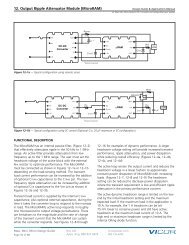
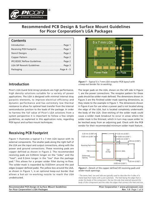
Figure 1 illustrates a typical 5 x 7 mm <strong>LGA</strong> layout with its<br />
external components. The smaller pads along the right half of<br />
the <strong>LGA</strong> are the input and output connections, along with the<br />
power and ground connections. These receiving pads are<br />
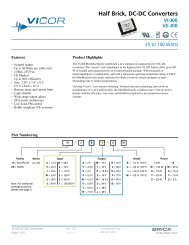
copper defined as shown in Figure 2. The recommended<br />
receiving pads are 0.05mm longer on the “sides” and the<br />
“heel”, and 0.2mm longer in the “toe” than the package<br />
pad. 1 This allows <strong>for</strong> a proper solder fillet during re-flow.<br />
The solder-mask is expanded by 0.025mm around the pad<br />
edges (copper defined pads). The yellow box around the <strong>LGA</strong>,<br />
as shown in Figure 1, is an optional keep-out border that<br />
allows a hot-air re-working nozzle to reach the <strong>LGA</strong><br />
unobstructed.<br />
Figure 1 – Typical 5 x 7 mm <strong>LGA</strong> receptor <strong>PCB</strong> layout with<br />
a keep-out border <strong>for</strong> re-working.<br />
The larger pads on the <strong>LGA</strong>, shown on the left side in Figure<br />
1, are the power connections. The receptor pattern <strong>for</strong> these<br />
pads should be solder-mask defined. The dimensions shown in<br />
Figure 3 are the finished solder mask opening dimensions, as<br />
they relate to the example in Figure 1. The dimensions shown<br />
in Figure 4 are <strong>for</strong> use when a power pad is not located along<br />
the edge of the <strong>LGA</strong>, but is located completely underneath<br />
the body of the <strong>LGA</strong>. Over-etching of the solder mask could<br />
cause a solder mask breakout to occur in areas where the<br />
solder mask is the thinnest, which in turn may cause solder to<br />
be leeched away from an adjoining pad. Check with the <strong>PCB</strong><br />
vendor <strong>for</strong> their recommended minimum solder mask feature.<br />
0.20 mm (0.008”)<br />
0.025 mm (0.001”)<br />
Receiving Pad<br />
TOE<br />
Soldermask<br />
Opening<br />
X<br />
<strong>LGA</strong><br />
I/O Pad<br />
0.05 mm (0.002”)<br />
0.025 mm (0.001”)<br />
0.025 mm (0.001”)<br />
0.05 mm (0.002”)<br />
HEEL<br />
0.025 mm (0.001”)<br />
Y<br />
0.05 mm (0.002”)<br />
Figure 2 – Details of the copper defined I/O receiving pads and<br />
solder-mask openings.<br />
1<br />
The terms heel, toe and side are typically used to describe the 4 sides of a<br />
metal lead that mates with a pcb substrate. The heel being the edge that is<br />
under the body of the component, the toe the side that extends beyond the<br />
body of the component and the sides the edges that connect the heel and toe.<br />
Recommended <strong>PCB</strong> <strong>Design</strong> & <strong>Surface</strong> <strong>Mount</strong> <strong>Guidelines</strong><br />
Picor Corporation • www.picorpower.com<br />
<strong>for</strong> Picor Corporation’s <strong>LGA</strong> Packages Rev. 1.0 Page 1 of 6
The values <strong>for</strong> X and Y, shown in Figures 2, 3 and 4, are the<br />
<strong>LGA</strong> pad dimensions and can be found at the end of this<br />
guide or in the corresponding Picor <strong>LGA</strong> product data sheet.<br />
0.20 mm (0.008”)<br />
0.025 mm (0.001”)<br />
TOE<br />
X<br />
<strong>LGA</strong><br />
Edge<br />
Power Pad<br />
0.025 mm (0.001”)<br />
HEEL<br />
Copper Pattern<br />
When designing a board using Picor’s <strong>LGA</strong> package, it is very<br />
important to make allowances <strong>for</strong> copper filled board area<br />
around the power pads. The power pads of the <strong>LGA</strong> should<br />
be connected directly to the polygon with solid connections<br />
on all sides, not with thermal relief pads. The greater the area<br />
of copper connected to the power pads of the <strong>LGA</strong>, the<br />
better the thermal per<strong>for</strong>mance of the <strong>LGA</strong> package. If there<br />
are internal layers available, then it is recommended that at a<br />
minimum, the copper area of the top layer be mirrored on<br />
inner layers with as many vias, on either side of the receiving<br />
pads, as can be reliably manufactured. The vias in Figure 5 are<br />
10mil holes with a 5mil annular ring and should be tented top<br />
and bottom with solder mask.<br />
Y<br />
Soldermask<br />
Opening<br />
0.025 mm (0.001”)<br />
Figure 3 – Solder-mask defined <strong>LGA</strong> edge power pads.<br />
0.025 mm (0.001”)<br />
X<br />
0.025 mm (0.001”)<br />
Figure 5 – Recommended blind and through-hole Via<br />
Construction (dimensions shown are minimum values).<br />
Soldermask<br />
Opening<br />
<strong>LGA</strong><br />
Internal<br />
Power Pad<br />
Figure 4 – Solder-mask defined <strong>LGA</strong> internal power pads.<br />
0.025 mm (0.001”)<br />
Y<br />
0.025 mm (0.001”)<br />
The downside of large areas of copper is the amount of heat<br />
required to reflow the power pads of the <strong>LGA</strong>. If the reflow<br />
zone’s temperature has to be greatly increased to reflow the<br />
<strong>LGA</strong>, then components mounted on smaller areas of copper<br />
could be thermally damaged. We recommend that routine<br />
reflow temperature profiling should be completed be<strong>for</strong>e<br />
assembling with a new <strong>PCB</strong> design to determine peak device<br />
temperatures during the SMT process.<br />
IPC/JEDEC Reflow <strong>Guidelines</strong><br />
Stencil <strong>Design</strong><br />
Picor recommends a 6mil thick stencil, with stencil openings<br />
of 80% of the receiving pad area. For solder mask defined<br />
openings, the receiving area is the same area as the solder<br />
mask opening.<br />
The 5 x 7 mm <strong>LGA</strong> package is designed to be re-flowed using<br />
lead-free solder, with a maximum reflow temperature of<br />
260°C <strong>for</strong> 20 to 40 seconds. The package can be maintained at<br />
a temperature above 217°C <strong>for</strong> 60 to 150 seconds.<br />
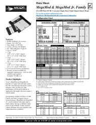
The reflow profile should adhere to the JEDEC standard,<br />
taken from IPC/JEDEC J-STD-020C July, 2004, shown in Figures<br />
6 and 7. Figure 7 is a lead-free reflow profile, but the 5 x 7<br />
mm <strong>LGA</strong> package is compatible with leaded solders as well.<br />
Recommended <strong>PCB</strong> <strong>Design</strong> & <strong>Surface</strong> <strong>Mount</strong> <strong>Guidelines</strong><br />
Picor Corporation • www.picorpower.com<br />
<strong>for</strong> Picor Corporation’s <strong>LGA</strong> Packages Rev. 1.0 Page 2 of 6
T P<br />
tp<br />
Critical Zone<br />
Ramp-up<br />
T L<br />
to T P<br />
T L<br />
Temperature<br />
Ts max<br />
Ts min<br />
ts<br />
Preheat<br />
t L<br />
Ramp-down<br />
25<br />
t 25°C to Peak<br />
Time<br />
Figure 6 –– IPC/JEDEC Classification Reflow Profile.<br />
Profile Feature<br />
Pb-Free Assembly<br />
Average Ramp-Up Rate<br />
(TS MAX to T P )<br />
3 °C / second max.<br />
Preheat<br />
– Temperature Min (Ts MIN ) 150 °C<br />
– Temperature Max (Ts MAX ) 200 °C<br />
– Time (ts MIN to ts MAX ) 60 – 180 seconds<br />
Time maintained above<br />
– Temperature (T L ) 217 °C<br />
–Time(t L )<br />
60 – 150 seconds<br />
Peak/Classification Temperature (T P ) 260 °C +0/-5 °C<br />
Time within 5 °C<br />
20 – 40 seconds<br />
of actual Peak Temperature (t P )<br />
Ramp-Down Rate<br />
Time 25 °C to Peak Temperature<br />
6 °C / second max.<br />
8 minutes max.<br />
NOTE: All temperatures refer to topside of the package measured in<br />
the package body surface"<br />
<strong>LGA</strong> Rework <strong>Guidelines</strong><br />
The 5 x 7 mm <strong>LGA</strong> package is capable of being re-worked in a<br />
non-destructive manner using standard hot-air reworking<br />
stations. Care must be taken that the temperature the<br />
package is exposed to does not exceed the maximum reflow<br />
temperature of 260°C. Pre-heating of the board can be done<br />
to minimize the time the peak re-work temperature is<br />
applied. Also, solder flux should be applied to the area to<br />
insure proper solder reflow.<br />
Figure 7 –– IPC/JEDEC Reflow Profiles table.<br />
Recommended <strong>PCB</strong> <strong>Design</strong> & <strong>Surface</strong> <strong>Mount</strong> <strong>Guidelines</strong><br />
Picor Corporation • www.picorpower.com<br />
<strong>for</strong> Picor Corporation’s <strong>LGA</strong> Packages Rev. 1.0 Page 3 of 6
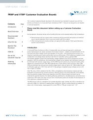
Picor 5 x 7 mm <strong>LGA</strong> Packages:<br />
Picor’s 5 x 7 mm <strong>LGA</strong> package is based on an industry standard 0.8mm pitch MLCC package.<br />
PIN 1<br />
5.00mm ±0.03mm<br />
0.45mm ±0.05mm<br />
1.20mm<br />
3.20mm<br />
2.40mm<br />
17<br />
1 2<br />
3<br />
B<br />
7.00mm ±0.03mm<br />
PI2xxx<br />
YYWW<br />
0.80mm<br />
0.00mm<br />
0.80mm<br />
2.00mm<br />
2.80mm<br />
13<br />
12<br />
8<br />
7<br />
A<br />
2.00mm ±0.06mm<br />
0.80mm<br />
0.30mm ±0.05mm<br />
0.40mm ±0.05mm<br />
0.40mm ±0.05mm<br />
A: I/O Pads (Pins 6 - 14)<br />
Copper Defined<br />
1.20mm ±0.05mm<br />
B: Power Pads (Pins 1 - 5, 15 - 17)<br />
Soldermask Defined<br />
0.89mm 1.60mm 0.80mm 0.80mm 1.20mm 0.80mm 0.53mm<br />
1.09mm<br />
0.73mm<br />
Pin 1<br />
0.80mm<br />
1.20mm<br />
0.80mm<br />
1.20mm<br />
Notes:<br />
SM = Solder mask defined<br />
Pad = Copper defined<br />
All dimensions are finished values.<br />
Drawing is "top view" perspective.<br />
0.80mm<br />
0.80mm<br />
SM 0.63mm<br />
PAD 0.55mm<br />
SM 1.25mm<br />
SM 0.55mm<br />
PAD 0.50mm<br />
SM 0.60mm<br />
Figure 8 –– 5 x 7 mm, 17 Lead Package. (PI2121, PI2123, PI2125)<br />
Recommended <strong>PCB</strong> <strong>Design</strong> & <strong>Surface</strong> <strong>Mount</strong> <strong>Guidelines</strong><br />
Picor Corporation • www.picorpower.com<br />
<strong>for</strong> Picor Corporation’s <strong>LGA</strong> Packages Rev. 1.0 Page 4 of 6
5.00mm ±0.03mm<br />
PIN 1<br />
0.45mm ±0.05mm<br />
3.20mm<br />
2.40mm<br />
C<br />
17<br />
1.20mm<br />
1 2<br />
3<br />
B<br />
7.00mm ±0.03mm<br />
PI2xxx<br />
YYWW<br />
0.80mm<br />
0.00mm<br />
0.80mm<br />
2.00mm<br />
2.80mm<br />
13<br />
12<br />
8<br />
7<br />
A<br />
2.00mm ±0.06mm<br />
0.80mm<br />
0.30mm ±0.05mm<br />
0.40mm ±0.05mm<br />
1.20mm ±0.05mm<br />
0.40mm ±0.05mm<br />
A: I/O Pads (Pins 6 - 14)<br />
Copper Defined<br />
1.20mm ±0.05mm<br />
B: Power Pads (Pins 1 - 5, 15 - 17)<br />
Soldermask Defined<br />
0.50mm ±0.05mm<br />
C: Internal Power Pads<br />
Soldermask Defined (8 Places)<br />
0.89mm<br />
1.60mm<br />
0.80mm<br />
0.80mm<br />
0.80mm<br />
1.20mm<br />
0.53mm<br />
1.09mm<br />
0.73mm<br />
Pin 1<br />
0.80mm<br />
1.20mm<br />
1.20mm<br />
Notes:<br />
SM = Solder mask defined<br />
Pad = Copper defined<br />
All dimensions are finished values.<br />
Drawing is "top view" perspective.<br />
SM 0.55mm<br />
0.80mm<br />
0.80mm<br />
SM 1.25mm<br />
0.80mm<br />
SM 0.63mm<br />
PAD 0.55mm<br />
SM 1.25mm<br />
Figure 9 –– 5 x 7 mm, 25 Lead Package. (PI2122)<br />
SM 0.55mm<br />
PAD 0.50mm<br />
SM 0.60mm<br />
Recommended <strong>PCB</strong> <strong>Design</strong> & <strong>Surface</strong> <strong>Mount</strong> <strong>Guidelines</strong><br />
Picor Corporation • www.picorpower.com<br />
<strong>for</strong> Picor Corporation’s <strong>LGA</strong> Packages Rev. 1.0 Page 5 of 6
Vicor’s comprehensive line of power solutions includes high-density AC-DC &<br />
DC-DC modules and accessory components, fully configurable AC-DC & DC-DC<br />
power supplies, and complete custom power systems.<br />
In<strong>for</strong>mation furnished by Vicor is believed to be accurate and reliable. However, no responsibility<br />
is assumed by Vicor <strong>for</strong> its use. No license is granted by implication or otherwise under any patent<br />
or patent rights of Vicor. Vicor components are not designed to be used in applications, such as<br />
life support systems, wherein a failure or malfunction could result in injury or death. All sales are<br />
subject to Vicor’s Terms and Conditions of Sale, which are available upon request.<br />
Specifications are subject to change without notice.<br />
Recommended <strong>PCB</strong> <strong>Design</strong> & <strong>Surface</strong> <strong>Mount</strong> <strong>Guidelines</strong><br />
Picor Corporation • www.picorpower.com<br />
<strong>for</strong> Picor Corporation’s <strong>LGA</strong> Packages Rev. 1.0 Page 6 of 6 7/08