Installation, Operation & Maintenace Manual - HEAT Inc
Installation, Operation & Maintenace Manual - HEAT Inc
Installation, Operation & Maintenace Manual - HEAT Inc

Create successful ePaper yourself
Turn your PDF publications into a flip-book with our unique Google optimized e-Paper software.
Commercial Series<br />
<strong>Installation</strong><br />
Instructions<br />
Health<br />
Relaxation<br />
Exhilaration<br />
Heat Spa Kur Therapy Development <strong>Inc</strong>
<strong>Inc</strong><br />
Spa Kur Therapy<br />
Development<br />
INSTALLATION, OPERATION & MAINTENANCE MANUAL<br />
MODELS: SW-10, SW-12 and SW-18<br />
COMMERCIAL SERIES<br />
GUIDELINES FOR STEAM ROOMS<br />
1. Walls, ceiling and fl oor must be completely covered with waterproof fi nish; tile, marble, stone or slate.<br />
2. Any smooth surface fl ooring that is used such as tile or marble, should include an anti-skid finish to<br />
avoid slipping and injury.<br />
3. Any exposed plaster, plasterboard or sheet rock surface must be well sealed with a commercial quality<br />
waterproof sealer urethane or epoxy, at least 3 coats.<br />
4. Use cement board, DO NOT use green board.<br />
5. Ceiling should be pitched away from the door 1-1/2” per foot or constructed in a gable confi guration to<br />
prevent condensation from dripping.<br />
6. Built-in seat should be slightly pitched to allow for condensation run-off.<br />
7. Steam room must be completely enclosed with walls, door, fl oor and ceiling, but should not be vapor<br />
proof. A slight opening of approximately 1/4” is desired to create movement of the steam.<br />
8. A standard glass shower door is suffi cient, a special door is not necessary.<br />
9. Make sure there is a fl oor drain for condensation run-off and cleaning.<br />
10. Do not install a fan inside steam room. Hot steam rises and will escape through fl apper.<br />
11. Windows that are part of the steam room enclosure should be double paned.<br />
12. If using lights inside steam room they must be vapor proof.<br />
13. A deionizer or filter hooked up on incoming water line is helpful in hard/corrosive water areas.<br />
14. Install the steam generator to hot side of water to reduce heating time, unless a water softener is<br />
hooked up. Water softeners are usually hooked up to hot side.<br />
15. Check local utility line voltage and choose appropriate steam generator voltage; 208 Volt or 240 Volt.<br />
16. Make sure the steam generator is installed in an upright and level position and is in a location that is<br />
ACCESSIBLE for Water Level Sensor Probe maintenance.<br />
17. Steam generator should never be located where it is exposed to outside weather conditions, freezing<br />
temperatures, near fl ammable materials or inside the steam room.<br />
H-e-a-t Spa Kur Therapy Development <strong>Inc</strong> — www.h-e-a-t.com 2/20
<strong>Inc</strong><br />
Spa Kur Therapy<br />
Development<br />
INSTALLATION, OPERATION & MAINTENANCE MANUAL<br />
CONFIRM THE CORRECT MODEL HAS BEEN SELECTED<br />
1.<br />
Multiply the length x width x height of the steam room enclosure (A)<br />
A<br />
Cubic Feet<br />
2.<br />
3.<br />
** If enclosure walls are constructed of glass, marble, concrete, stone<br />
or slate:<br />
Copy the Figure from box (A) to box (B)<br />
Total (A) and (B) for total Cubic Feet (C)<br />
B<br />
C<br />
Cubic Feet<br />
4.<br />
Cubic Feet<br />
INCREASE (C) FOR EACH OF THE FOLLOWING FEATURES OF STEAM ROOM ENCLOSURE<br />
Add 15% for an exterior outside wall<br />
D<br />
Add 15% for each additional foot for rooms over 8’ high<br />
E<br />
Add 15% for an extra glass panel in addition to the door<br />
F<br />
5.<br />
Add boxes (C) through (F) for total Cubic Feet (G)<br />
Select recommended model from the<br />
GENERATOR SIZING GUIDE on Page 3<br />
G<br />
Cubic Feet<br />
** Certain materials used in the construction of steam rooms may require a larger unit<br />
to produce the desired conditions. Consult an Architect, Designer, Contractor or the<br />
factory to determine all factors necessary to build a suitable and safe steam room.<br />
Larger Generators are available.<br />
• Steam-Whirl’s revolutionary LED self analysis system in the Standard Series generator<br />
simplifi es installation and monitors for proper electrical and water feed at all times.<br />
• All stainless steel tanks and components.<br />
• Extensive factory testing for all conditions.<br />
• 6 year limited manufacturing warranty.<br />
• Factory assistance provided from blueprint to fi nished product.<br />
H-e-a-t Spa Kur Therapy Development <strong>Inc</strong> — www.h-e-a-t.com 3/20
<strong>Inc</strong><br />
Spa Kur Therapy<br />
Development<br />
INSTALLATION, OPERATION & MAINTENANCE MANUAL<br />
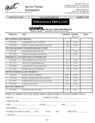
GENERATOR SIZING GUIDE<br />
MODEL<br />
MAXIMUM<br />
CUBIC<br />
FEET<br />
CAPACITY<br />
KW VOLTS PHASE AMPS<br />
BREAKER<br />
SIZE<br />
WIRE<br />
SIZE<br />
@ 100’<br />
SW-10BD<br />
1 42 60A 6AWG<br />
SW-10-3BD<br />
240<br />
3 24 30A 10AWG<br />
SW-10-8BD<br />
400 10.0<br />
1 48 60A 6AWG<br />
SW-10-83BD<br />
208<br />
3 28 40A 10AWG<br />
SW-12BD<br />
1 50 70A 6AWG<br />
SW-12-3BD<br />
240<br />
3 29 40A 10AWG<br />
SW-12-8BD<br />
500 11.5<br />
1 58 80A 4AWG<br />
SW-12-83BD<br />
208<br />
3 32 50A 8AWG<br />
SW-18BD<br />
1 75 100A 3AWG<br />
SW-18-3BD<br />
240<br />
3 43 60A 6AWG<br />
SW-18-8BD<br />
800 18<br />
1 87 110A 2AWG<br />
SW-18-83BD<br />
208<br />
3 50 70A 6AWG<br />
BD = Blowdown (Factory Installed)<br />
Commercial Series models contain (1) Steam Generator w/Pressure Gauge and Site Glass; (1) Accessory<br />
Kit in choice of fi nish, (1) Automatic Blowdown w/24Hr Time Clock., Probe Maintenance Instructions and<br />
<strong>Installation</strong> Instructions.<br />
H-e-a-t Spa Kur Therapy Development <strong>Inc</strong> — www.h-e-a-t.com 4/20
<strong>Inc</strong><br />
Spa Kur Therapy<br />
Development<br />
INSTALLATION, OPERATION & MAINTENANCE MANUAL<br />
PRE-INSTALLATION<br />
1. Verify correct model has been sized for the cubic feet and type of steam room using the GENERATOR SIZING<br />
GUIDE on Page 3.<br />
2. Check that the electrical power supply available is adequate for the voltage, amps and phase of the generator<br />
warning<br />
ELECTRICAL SHOCK HAZARD<br />
3. All installations and service must be performed by a qualifi ed electrician and/or plumber and conform to all local<br />
and national codes. The generator must be installed and operated according to the instructions. Failure to do<br />
so will void the warranty and could lead to injury or death due to the live electrical components involved with<br />
installation.<br />
4. Physical size of the unit and accessibility for plumbing service and Water Level Sensor Probe maintenance must<br />
be considered.<br />
SAFETY INFORMATION<br />
warning<br />
1 Prolonged exposure to steam may cause hyperthermia. Hyperthermia occurs when the internal temperature<br />
of the body reaches a level several degrees above the normal body temperature of 98.6°F. The symptoms of<br />
hyperthermia include an increase in the internal temperature of the body, dizziness, lethargy, drowsiness and<br />
fainting.<br />
2. The effects of hyperthermia include: Failure to perceive heat; failure to recognize the need to exit the steam<br />
room; unawareness of impending risk; fetal damage in pregnant women; physical inability to exit the steam<br />
room; and unconsciousness.<br />
3. The use of alcohol, drugs, or medication can greatly increase the risk of hyperthermia.<br />
4. Some aroma therapy oils may cause an allergic reaction - USE WITH CAUTION.<br />
5. Children under the age of 16 should not use the steam room without an adult.<br />
6. The steam head, steam line, plumbing and other components become hot during operation. The steam head<br />
and plumbing must be installed in a location so that it cannot come into contact with users to prevent burning or<br />
scalding. Insulate plumbing lines for additional protection.<br />
7. After the system is shut down the components will remain hot. Do not come into contact with the steam head or<br />
components until the system has returned to a normal temperature.<br />
H-e-a-t Spa Kur Therapy Development <strong>Inc</strong> — www.h-e-a-t.com 5/20
STEAM-WHIRL<br />
Steam<br />
Room<br />
<strong>Inc</strong><br />
Spa Kur Therapy<br />
Development<br />
INSTALLATION, OPERATION & MAINTENANCE MANUAL<br />
1. Place the steam generator, optional Thermostat Controller (TC-2) and optional 24 Hr 7 Day Timer in a location<br />
NOT ACCESSIBLE TO CLIENTS but that is ACCESSIBLE TO MAINTENANCE and not more than 40’ from<br />
steam room. ALL steam generators require maintenance.<br />
2. The steam generator should never be located where it is exposed to outside weather conditions or freezing<br />
temperatures, near fl ammable materials, inside the steam room or where access cannot be gained to Water Level<br />
Sensor Probe for maintenance.<br />
3. Install in an upright and level position.<br />
INSTALLATION<br />
4. The serial number label should be visible and accessible for service.<br />
5. A minimum of 2’ of open unobstructed space must be left around the top and sides of the generator to allow for<br />
heat dissipation and accessibility for service.<br />
Water<br />
Supply<br />
Line<br />
Power Box<br />
&<br />
Power Disconnect<br />
24 Hr/7 Day Timer<br />
for TC-2<br />
Temperature<br />
Sensor Probe<br />
TC-2<br />
Optional<br />
60 Min<br />
Timer<br />
24 H Timer<br />
for<br />
Blowdown<br />
Site Glass<br />
A<br />
A<br />
B<br />
C<br />
E<br />
G<br />
D<br />
F<br />
H-e-a-t Spa Kur Therapy Development <strong>Inc</strong> — Tel 707-942-6633 — Fax 707-942-0734 — www.h-e-a-t.com 6/20
<strong>Inc</strong><br />
Spa Kur Therapy<br />
Development<br />
INSTALLATION, OPERATION & MAINTENANCE MANUAL<br />
PLUMBING<br />
IMPORTANT:<br />
All plumbing should be done by a qualified plumber and must conform to all local and<br />
national plumbing codes.<br />
warning<br />
ELECTRICAL SHOCK HAZARD<br />
POWER MUST BE DISCONNECTED AT THE MAIN ELECTRICAL SUPPLY BEFORE MAKING ANY CONNECTIONS<br />
1. Use copper or brass fi ttings only. DO NOT use galvanized or black iron.<br />
DO NOT USE PLUMBERS PUTTY ON ANY WATER CONNECTIONS<br />
2. A union must be installed close to the generator to facilitate easy removal, if necessary.<br />
3. Tap off any existing water supply line, hot or cold, with 1/2” copper tubing or 1/2” NPT pipe.<br />
4. Flush at least 1 gallon of water to clear line prior to connecting to the 1/4” compression water inlet fitting<br />
(A in Plumbing Diagram) on generator. When tightening this fi tting, use two wrenches to avoid strain on Water<br />
Solenoid Valve inside generator.<br />
5. Install a shut-off valve (B in Plumbing Diagram) on the water supply line as close to the generator as possible.<br />
DO NOT USE A SADDLE VALVE<br />
6. For best results Install an inline fi lter between shut-off valve and generator.<br />
7. For best results, steam generator should be higher than the steam head. If this is not possible, steam line must<br />
slope 1/4” per foot minimum to steam room.<br />
8. Connect 3/4” copper tubing or 3/4” NPT pipe to steam outlet (C in Plumbing Diagram) and run to approximately<br />
8-12” off finished fl oor in shower or just above deck of bathtub on any wall not interfering with user and at least<br />
12-14” away from seat or bench. For areas with acrylic or other non-heat resistant fl oors, install steam head 20-<br />
30” off fi nished floor in shower.<br />
DO NOT PLACE A SHUT-OFF VALVE ON STEAM OUTLET LINE, ONLY ON WATER SUPPLY LINE.<br />
WARNING: DO NOT PLUMB VALLEYS AND DIPS WHERE WATER FROM STEAM CONDENSATION IN THE<br />
LINE COULD COLLECT AND CAUSE BLOCKAGE.<br />
9. Leave approximately 1/2” of threads protruding from fi nished wall. Place escutcheon on threads and screw on<br />
steam head (D in Plumbing Diagram). Take care not to scratch the steam head with wrench. Rotate steam head<br />
until open slot is facing down.<br />
10. IMPORTANT: Steam head must be installed to prevent users from coming into direct contact with the steam head<br />
and the steam coming from it. While in use the steam head and steam coming directly from it will become hot and<br />
can burn. An optional Steam Diffuser is recommended for small steam rooms.<br />
11. Connect 3/4” copper tubing or NPT pipe to the pressure relief valve (E in Plumbing Diagram) and 1/2” copper<br />
tubing or NPT pipe if using an optional Blowdown (F in Plumbing Diagram). Both of these items must be<br />
installed with a union and plumbed to drain to an approved location.<br />
DO NOT PLUMB THE PRESSURE RELIEF VALVE LINE TO THE STEAM LINE OR INTO THE STEAM<br />
ROOM.<br />
H-e-a-t Spa Kur Therapy Development <strong>Inc</strong> — www.h-e-a-t.com 7/20
<strong>Inc</strong><br />
Spa Kur Therapy<br />
Development<br />
INSTALLATION, OPERATION & MAINTENANCE MANUAL<br />
PLUMBING DIAGRAM<br />
Water Supply Line<br />
Pressure Gauge<br />
G<br />
Classic Timer<br />
B<br />
24Hr Timer<br />
for Blowdown<br />
STEAM-WHIRL<br />
STEAM BATH GENERATOR<br />
MODEL NO SER NO<br />
VOLTS PH AMPS KW<br />
MFG BY STEAM-WHIRL PRODUCTS<br />
LAS VEGAS NV 89118 (702) 270-2124<br />
LISTED 16K3<br />
STEAMBATH<br />
EQUIPMENT C US<br />
®<br />
LISTED<br />
Site Glass<br />
A<br />
C<br />
E<br />
H-e-a-t Spa Kur Therapy Development <strong>Inc</strong> — www.h-e-a-t.com 8/20<br />
F
<strong>Inc</strong><br />
Spa Kur Therapy<br />
Development<br />
INSTALLATION, OPERATION & MAINTENANCE MANUAL<br />
ELECTRICAL<br />
IMPORTANT:<br />
All wiring should be done by a qualified electrician and must conform to all local and<br />
national electrical codes.<br />
warning<br />
ELECTRICAL SHOCK HAZARD<br />
POWER MUST BE DISCONNECTED AT THE MAIN ELECTRICAL SUPPLY BEFORE MAKING ANY CONNECTIONS<br />
1. Supply wiring should be sized in accordance with the voltage and amps of the unit and suitable for 90°.<br />
2. A separate circuit breaker must be installed and sized according to the GENERATOR SIZING GUIDE (Page 3).<br />
3. Locate the electrical supply line knockout on top of generator enclosure. If this knockout is not going to be used,<br />
DO NOT drill a knockout on the left side of the enclosure (drop down door facing out). Running a electrical supply<br />
line through the left side of the enclosure could potentially damage the low voltage circuit board.<br />
4. Strip 1/2” insulation from the two (2) power wires and the one (1) ground wire.<br />
5. Bring the two (2) incoming electrical supply wires to L1 and L2 and the one (1) ground wire to the ground<br />
terminal.<br />
6. If unit is a 3 Phase, bring the three (3) incoming electrical supply wire to L1, L2 and L3 and the one (1) ground wire<br />
to the ground terminal.<br />
7. Install a power disconnect near unit.<br />
8. Install Timer (G in Plumbing Diagram) according to Timer <strong>Installation</strong> Instructions.<br />
AUTOMATIC BLOWDOWN<br />
1. All commercial series genrators are equiped with factory installed automatic blowdown, a two position spring return<br />
valve designed to electronically drain the water from the heating tank.<br />
2. Also installed with all commercial generators is a 24 hour time clock wired in series with the automatic blowdown.<br />
The 24 hour timer allows the business owner to regulate when the blow down function is performed. It is ideal to<br />
set the timer to operate when the steam room is not in high demand.<br />
3. The automatic blowdown feature keeps stagnant water from sitting in the tank between uses giving the generator a<br />
longer life and reducing the amount of required maintenance.<br />
H-e-a-t Spa Kur Therapy Development <strong>Inc</strong> — www.h-e-a-t.com 9/20
<strong>Inc</strong><br />
Spa Kur Therapy<br />
Development<br />
INSTALLATION, OPERATION & MAINTENANCE MANUAL<br />
GENERATOR DIAGRAM<br />
4” 4½”<br />
STEAM-WHIRL<br />
STEAM BATH GENERATOR<br />
MODEL NO SER NO<br />
VOLTS PH AMPS KW<br />
MFG BY STEAM-WHIRL PRODUCTS<br />
LAS VEGAS NV 89118 (702) 270-2124<br />
LISTED 16K3<br />
STEAMBATH<br />
EQUIPMENT C US<br />
®<br />
LISTED<br />
4”<br />
21½”<br />
20¼”<br />
8¼”<br />
Water Supply Line<br />
Steam Output Line<br />
Pressure Relief Valve<br />
1/2” Copper Line, 1/2” NPT Female Thread<br />
3/4” Copper Line, 3/4” NPT Female Thread<br />
3/4” Copper Line, 3/4” NPT Female Thread, Valve Supplied<br />
H-e-a-t Spa Kur Therapy Development <strong>Inc</strong> — www.h-e-a-t.com 10/20
<strong>Inc</strong><br />
Spa Kur Therapy<br />
Development<br />
INSTALLATION, OPERATION & MAINTENANCE MANUAL<br />
COMMERCIAL SERIES WIRING DIAGRAM - SINGLE PHASE<br />
SW-10 & SW-12<br />
Power<br />
Ground<br />
Ground<br />
Plate Screw<br />
H2O Solenoid Valve<br />
Capacitor Jumper<br />
Wire Assy<br />
Plate Screw<br />
Hi sens<br />
Ground<br />
Lo sens<br />
WL-1<br />
CL-1<br />
WL-2<br />
CL-2<br />
L-1<br />
L-2<br />
L-1<br />
Coil<br />
L-2<br />
L-1<br />
L-2<br />
Plate Screw<br />
Ground<br />
Contactor<br />
BUSS<br />
FUSE<br />
BAF-1<br />
L-2<br />
BUSS<br />
FUSE<br />
BAF-1<br />
L-1<br />
PCB Controller<br />
Fuses<br />
T-1<br />
T-2<br />
208/240V Timer 208/240 Load<br />
T<br />
1<br />
2<br />
3<br />
4 5<br />
TIMER COM NO NC<br />
Ground<br />
Probe<br />
STEAM-WHIRL<br />
Classic<br />
Mechanical<br />
Timer<br />
Heater Tank<br />
Ground<br />
Hi Limit Sensor<br />
Ground<br />
Blow<br />
Down<br />
Valve<br />
H-e-a-t Spa Kur Therapy Development <strong>Inc</strong> — www.h-e-a-t.com 11/20
<strong>Inc</strong><br />
Spa Kur Therapy<br />
Development<br />
INSTALLATION, OPERATION & MAINTENANCE MANUAL<br />
COMMERCIAL SERIES WIRING DIAGRAM - SINGLE PHASE<br />
SW-18<br />
Power<br />
Ground<br />
Plate Screw<br />
Ground<br />
WL-1<br />
Plate Screw<br />
L-1<br />
H2O Solenoid Valve<br />
L-1<br />
Capacitor Jumper<br />
Wire Assy<br />
Hi sens<br />
Ground<br />
Lo sens<br />
CL-1<br />
WL-2<br />
CL-2<br />
L-1<br />
L-2<br />
Coil<br />
Coil<br />
L-2<br />
L-2<br />
Plate Screw<br />
Ground<br />
BUSS<br />
FUSE<br />
BAF-1<br />
L-2<br />
Contactor<br />
BUSS<br />
FUSE<br />
BAF-1<br />
L-1<br />
PCB Controller<br />
Fuses<br />
T-1<br />
T-2<br />
208/240V Timer 208/240 Load<br />
T<br />
1<br />
2<br />
3<br />
4 5<br />
TIMER COM NO NC<br />
Ground<br />
Probe<br />
STEAM-WHIRL<br />
Classic<br />
Mechanical<br />
Timer<br />
Heater Tank<br />
Ground<br />
Ground<br />
Hi Limit Sensor<br />
Blow<br />
Down<br />
Valve<br />
H-e-a-t Spa Kur Therapy Development <strong>Inc</strong> — www.h-e-a-t.com 12/20
<strong>Inc</strong><br />
Spa Kur Therapy<br />
Development<br />
INSTALLATION, OPERATION & MAINTENANCE MANUAL<br />
COMMERCIAL SERIES WIRING DIAGRAM - THREE PHASE<br />
SW-10, SW-12 and SW-18<br />
Power<br />
Ground<br />
Ground<br />
Plate Screw<br />
H2O Solenoid Valve<br />
Capacitor Jumper<br />
Wire Assy<br />
Plate Screw<br />
WL-1<br />
L-1<br />
L-1<br />
Hi sens<br />
Ground<br />
Lo sens<br />
CL-1<br />
WL-2<br />
CL-2<br />
L-1<br />
L-2<br />
L-3<br />
Coil<br />
L-2<br />
Coil<br />
L-3<br />
L-2<br />
L-3<br />
Plate Screw<br />
Ground<br />
BUSS<br />
FUSE<br />
BAF-1<br />
L-2<br />
Contactor<br />
BUSS<br />
FUSE<br />
BAF-1<br />
L-1<br />
PCB Controller<br />
Fuses<br />
T-1<br />
T-2<br />
208/240V Timer 208/240 Load<br />
T<br />
1<br />
2<br />
3<br />
4 5<br />
TIMER COM NO NC<br />
Ground<br />
Probe<br />
STEAM-WHIRL<br />
Classic<br />
Mechanical<br />
Timer<br />
Heater Tank<br />
Ground<br />
Ground<br />
Hi Limit Sensor<br />
Blow<br />
Down<br />
Valve<br />
H-e-a-t Spa Kur Therapy Development <strong>Inc</strong> — www.h-e-a-t.com 13/20
<strong>Inc</strong><br />
Spa Kur Therapy<br />
Development<br />
INSTALLATION, OPERATION & MAINTENANCE MANUAL<br />
CLASSIC SERIES TIMER INSTALLATION<br />
Step 5<br />
Step 4<br />
2½” min<br />
Step 6<br />
Step 2<br />
STEAM-WHIRL<br />
Step 7<br />
1. Turn power off at circuit breaker or fuse panel.<br />
2. Timer should be located on a wall outside the steam room, 5’ away.<br />
3. Run 14 AWG wire from back of timer 1-NO and 1-C to T1 & T2 on terminal block inside steam generator.<br />
4. Insert wired timer into a 2-1/2” (min) deep wall box with “TOP” indicated on front cover in proper position.<br />
5. Fasten to wall box using the two (2) screws supplied.<br />
6. Fasten the wall plate to the timer using the two (2) screws supplied with the plate. The screws must be selftapped<br />
into the timer body and will require gentle inward pressure while fi rmly turning the screw.<br />
7. Position small plastic timer dial so that “OFF” is in the up position. Install the hex nut and tighten.<br />
8. Push knob onto timer shaft, handle facing down.<br />
SYSTEM INITIALIZATION<br />
1. After connections are completed, make sure power and water are on.<br />
2. Turn on timer and allow suffi cient time for unit to react.<br />
3. Timer can be turned off manually before set time has elapsed.<br />
H-e-a-t Spa Kur Therapy Development <strong>Inc</strong> — Tel 707-942-6633 — Fax 707-942-0734 — www.h-e-a-t.com 14/20
<strong>Inc</strong><br />
Spa Kur Therapy<br />
Development<br />
INSTALLATION, OPERATION & MAINTENANCE MANUAL<br />
TC-2 TEMPERATURE CONTROL to 60 MIN TIMER WIRING DIAGRAM<br />
TEMPERATURE CONTROL<br />
#90-4325 CLASSIC 60 MIN MECHANICAL TIMER<br />
C<br />
2 TOP<br />
1<br />
NO<br />
PART NO:<br />
C9360NONC<br />
240 120 COM<br />
Stage<br />
1<br />
NC 2<br />
1<br />
C<br />
NC NO<br />
C<br />
L1<br />
L2<br />
T1<br />
T2<br />
TERMINAL BLOCK<br />
ON STEAM UNIT<br />
H-e-a-t Spa Kur Therapy Development <strong>Inc</strong> — www.h-e-a-t.com 15/20
<strong>Inc</strong><br />
Spa Kur Therapy<br />
Development<br />
INSTALLATION, OPERATION & MAINTENANCE MANUAL<br />
TC-2 TEMPERATURE CONTROL TO TIME CLOCK WIRING DIAGRAM<br />
TEMPERATURE CONTROL<br />
#4320 TIMER 24HR 7DAY<br />
208/240V TIMER, 208/240V LOAD<br />
T<br />
240 120 COM<br />
1 2 3 4 5<br />
Stage<br />
1<br />
NC NO<br />
C<br />
TIMER COM NO NC<br />
L1<br />
L2<br />
T1<br />
T2<br />
TERMIAL BLOCK<br />
ON STEAM UNIT<br />
H-e-a-t Spa Kur Therapy Development <strong>Inc</strong> — www.h-e-a-t.com 16/20
<strong>Inc</strong><br />
Spa Kur Therapy<br />
Development<br />
INSTALLATION, OPERATION & MAINTENANCE MANUAL<br />
MAINTENANCE<br />
warning<br />
ELECTRICAL SHOCK HAZARD<br />
POWER MUST BE DISCONNECTED AT THE MAIN ELECTRICAL SUPPLY BEFORE PERFORMING ANY<br />
MAINTENANCE<br />
1. The steam generator is designed for unattended operation and requires little maintenance.<br />
2. Water Level Sensor Probe maintenance is as follows:<br />
• Shut off main electrical breaker.<br />
• Open dropdown door in front panel of generator enclosure and with a volt meter test that there is not<br />
voltage on power side of the Terminal Block L1 and L2. (See DIAGRAMS on Pages 10, 11 and 12)<br />
• On left side of heater tank locate the Water Level Sensor Probe and disconnect red and black wires<br />
from the top.<br />
• Carefully unscrew Water Level Sensor Probe.<br />
• Sand off any calcium build-up or debris on sensor tips.<br />
DO NOT CUT OR TRIM SENSOR WIRES.<br />
• Apply white teflon tape around thread.<br />
• Carefully screw Water Level Sensor Probe back in.<br />
• Reinstall red and black wires to top of sensor.<br />
• Turn on main electrical breaker.<br />
WATER LEVEL SENSOR PROBE<br />
NOTE:<br />
This maintenance is suggested for any service specialist. Iron content in local water will determine the<br />
frequency of probe service. Start out at least once a month and if the probe is clean and not coated,<br />
then try every two months, etc. More frequent servicing of the probe may be needed if the unit is in an<br />
extremely hard water area or the water is supplied by a well.<br />
H-e-a-t Spa Kur Therapy Development <strong>Inc</strong> — www.h-e-a-t.com 17/20
<strong>Inc</strong><br />
Spa Kur Therapy<br />
Development<br />
INSTALLATION, OPERATION & MAINTENANCE MANUAL<br />
MODEL #<br />
DESCRIPTION<br />
SERIAL #<br />
____________________________________________________________<br />
____________________________________________________________<br />
____________________________________________________________<br />
WATER SENSOR PROBE MAINTENANCE SCHEDULE:<br />
1st Cleaning Suggested: ______________________________________________________<br />
2nd Cleaning Check: ___________________________________________________________<br />
3rd Cleaning Check: ___________________________________________________________<br />
____________________________________________________________________________<br />
____________________________________________________________________________<br />
____________________________________________________________________________<br />
____________________________________________________________________________<br />
____________________________________________________________________________<br />
____________________________________________________________________________<br />
____________________________________________________________________________<br />
____________________________________________________________________________<br />
____________________________________________________________________________<br />
____________________________________________________________________________<br />
____________________________________________________________________________<br />
____________________________________________________________________________<br />
____________________________________________________________________________<br />
____________________________________________________________________________<br />
____________________________________________________________________________<br />
H-e-a-t Spa Kur Therapy Development <strong>Inc</strong> — www.h-e-a-t.com 18/20
WARRANTY<br />
Steam-Whirl Products warranties its products to be free of<br />
defects in workmanship and material, under normal use<br />
and maintenance, for a period of (6) years from the date<br />
of original purchase.<br />
Steam-Whirl Products liability under this warranty shall<br />
be limited to repair or replacement of products that have<br />
been determined to be defective in either materials of<br />
workmanship by an agent or representative of Steam-<br />
Whirl Products. If repair or replacement cannot be made<br />
on the premises by such agent or representative then the<br />
product should be sent to the service facility.<br />
Technical Service<br />
STEAM-WHIRL PRODUCTS<br />
3775 W Teco Ave #5<br />
Las Vegas, NV 89118-6827<br />
800-232-7832<br />
Products being sent to the service facility need to have prior<br />
approval and an RMA # (RETURNED MERCHANDISE<br />
AUTHORIZATION #) assigned. The products are to be<br />
packed in a well padded box, include RMA #, name, return<br />
address and daytime phone number along with a short<br />
description of problems. Mail or ship the unit, prepaid, to<br />
the above address.<br />
If the product is returned for a defect other than in materials<br />
or workmanship a reasonable charge will be made for<br />
parts, labor and shipping.<br />
This warranty shall be void and/or does not cover the<br />
following:<br />
1) Charges for parts or labor incurred before delivery<br />
of product to the address above.<br />
2) Any damage or defect caused by the installer,<br />
service company, user or any other person.<br />
3) <strong>Installation</strong> is not in accordance with the installation<br />
instructions provided with the product and/or<br />
installation by a person other than a licensed<br />
electrician or plumber.<br />
4) Deterioration due to normal wear and tear.<br />
5) Misuse, accident, incorrect operation, lack of<br />
proper maintenance, acts of God.<br />
6) Chemical corrosion.<br />
7) Alteration of product in any way.<br />
8) Exposure to outside weather conditions or<br />
temperatures.<br />
9) Contact shows evidence of short circuiting.<br />
10) Damage incurred in transit. The user or installer<br />
must examine the product immediately on delivery,<br />
before installation and report any damage to the<br />
carrier and the seller.<br />
11) Shipping costs to or from warranty service facility<br />
unless required by applicable law.<br />
12) Repair or replacement of any installation materials<br />
including, but not limited to, tiles, marble, etc or<br />
costs relating to obtaining access for repair,<br />
removal or reinstallation of the product or a<br />
replacement product.<br />
It is the responsibility of the user, installer or contractor to<br />
provide access for service and removal of the product, if<br />
necessary. Steam-Whirl Products is not responsible for<br />
any costs relating to accessing the product or its removal.<br />
The dealer, distributor and/or installer is responsible for<br />
knowing the applicable building codes and the dealer and/<br />
or distributor should notify the installer of same or confirm<br />
that the installer is aware of the applicable building codes.<br />
Building codes vary from location to location and Steam-<br />
Whirl Products cannot be responsible for knowledge of<br />
such codes.<br />
No other company or person has any authority to make<br />
any warranties or representations concerning Steam-<br />
Whirl Products or the products. Accordingly, Steam-Whirl<br />
Products is not responsible for any such warranties or<br />
representations.<br />
Steam-Whirl Products has not made and does not make<br />
any warranty, either expressed or implied, about the<br />
condition, merchantability, design or operation of the<br />
product or its fi tness for any particular use or purpose, or<br />
the quality of the materials or workmanship in the product<br />
or any other representation or warranty beyond the terms<br />
of this warranty<br />
Steam-Whirl Products shall not be liable for the user’s<br />
incidental or consequential damages. User acknowledges<br />
that the price of the product would be higher if Steam-<br />
Whirl Products were liable for consequential or incidental<br />
damages.<br />
Some states do not allow the exclusion or limitation,<br />
in whole or in part, of warranties or the exclusion of<br />
consequential or incidental damages, therefore the above<br />
limitation or exclusions may not be applicable to you.<br />
Steam-Whirl Products warranty obligation shall be<br />
discharged upon tender of repair or replacement. User’s<br />
refusal to accept the tender terminates Steam-Whirl<br />
Products’ warranty obligation.<br />
H-e-a-t Spa Kur Therapy Development <strong>Inc</strong> — www.h-e-a-t.com 19/20
Heat Spa Kur Therapy Development <strong>Inc</strong><br />
www.h-e-a-t.com — DrB @h-e-a-t.com