ADAM-4542 ADAM-4541
ADAM-4542 ADAM-4541
ADAM-4542 ADAM-4541

You also want an ePaper? Increase the reach of your titles
YUMPU automatically turns print PDFs into web optimized ePapers that Google loves.
Troubleshooting<br />
Possible reasons for malfunction<br />
Ø The TX and RX connections are reversed.<br />
Solution: Make sure the fiber connection is made<br />
so that the TX of one end is connected<br />
to the RX of the other.<br />
Ø Poor connection between the <strong>ADAM</strong>-<strong>4541</strong>/<strong>4542</strong><br />
and the communication port.<br />
Solution: Make sure the <strong>ADAM</strong>-<strong>4541</strong>/<strong>4542</strong> is<br />
securely plugged into the communication<br />
port.<br />
Ø Attenuation on the fiber causes the signal level to<br />
drop below the accepted level.<br />
Solution: Reduce the attenuation by reducing<br />
connector loss, transmission distances, etc.<br />
Ø The connection between the communication ports<br />
is neither DTE to DTE nor DCE to DCE<br />
connection.<br />
Solution: Add a converter to one of the optical<br />
modems, so that the pin assignments<br />
from the communication port to the<br />
modem are from pin 2 to pin 3 and from<br />
pin 3 to pin 2.<br />
Ø The fiber has been damaged.<br />
Solution: Repair or replace the fiber.<br />
Ø The <strong>ADAM</strong>-<strong>4541</strong>/<strong>4542</strong> has been damaged.<br />
Solution: Use the supplied software to perform<br />
a loop-back test of the optical<br />
modem. This will detect if the module<br />
is damaged.<br />
Power Supply<br />
For the ease of use in industrial environments,<br />
the <strong>ADAM</strong> modules are designed to accept<br />
industry standard +24 V unregulated power.<br />
DC<br />
Operation is guaranteed when using any power<br />
supply between +10 and +30 V . Power ripples<br />
DC<br />
must be limited to 5 V peak to peak, while the<br />
voltage in all cases must be maintained between<br />
+10 and +30 V . All power supply specifications<br />
DC<br />
are referenced at the module connector.<br />
The power cables should be selected according to<br />
the number of modules connected and the length<br />
of the power lines. When using a network with<br />
long cables, we advise the use of thicker wire, to<br />
limit line voltage drop. In addition to serious<br />
voltage drops, long voltage lines can also cause<br />
interference with communication wires.<br />
(R) +Vs<br />
(B) GND 10<br />
-<br />
+<br />
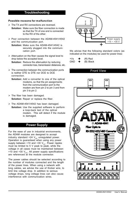
We advise that the following standard colors (as<br />
indicated on the modules) be used for power lines:<br />
+Vs è (R) Red<br />
GND è (B) Black<br />
Front View<br />
-<br />
+ Power supply<br />
+10 ~ +30 V<br />
<strong>ADAM</strong>-<strong>4541</strong>/<strong>4542</strong> User's Manual