ADAM 4000 Series
ADAM 4000 Series
ADAM 4000 Series

Create successful ePaper yourself
Turn your PDF publications into a flip-book with our unique Google optimized e-Paper software.
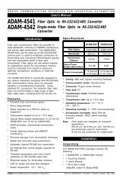
<strong>ADAM</strong> <strong>4000</strong><br />
<strong>Series</strong><br />
Data Acquisition Modules<br />
User's Manual
Copyright Notice<br />
<strong>ADAM</strong> <strong>4000</strong> <strong>Series</strong><br />
Data Acquisition Modules<br />
User's Manual<br />
This document is copyrighted, 1997, by Advantech Co., Ltd. All rights are<br />
reserved. Advantech Co., Ltd., reserves the right to make improvements to<br />
the products described in this manual at any time without notice.<br />
No part of this manual may be reproduced, copied, translated or transmitted<br />
in any form or by any means without the prior written permission of<br />
Advantech Co., Ltd. Information provided in this manual is intended to be<br />
accurate and reliable. However, Advantech Co., Ltd. assumes no responsibility<br />
for its use, nor for any infringements upon the rights of third parties<br />
which may result from its use.<br />
CE Notification<br />
The <strong>ADAM</strong>-<strong>4000</strong> series developed by Advantech Co., Ltd. has passed the<br />
CE test for environmental specifications when operated within an industrial<br />
enclosure (<strong>ADAM</strong>-4950-ENC). Therefore, in order to protect the <strong>ADAM</strong><br />
modules from being damaged by ESD (Electric Static Discharge), we<br />
strongly recommend that the use of CE-compliant industrial enclosure<br />
products when using any <strong>ADAM</strong> module.<br />
Acknowledgments<br />
<strong>ADAM</strong> is a trademark of Advantech Co., Ltd.<br />
IBM and PC are trademarks of International Business<br />
Machines Corporation.<br />
Part No.2001<strong>4000</strong>06 Seventh Edition<br />
Printed in Taiwan Sept. 2002
Table of Contents<br />
Chapter 1 Introduction ................................................................ 1-1<br />
1.1 Overview ............................................................................................... 1-2<br />
1.2 Applications ......................................................................................... 1-4<br />
Chapter 2 Installation Guideline ................................................ 2-1<br />
2.1 System Requirements to set up an <strong>ADAM</strong> network ............................ 2-3<br />
2.2 Basic configuration and hook-up ........................................................ 2-6<br />
2.3 Baud rate and Checksum ................................................................... 2-9<br />
2.4 Multiple Module Hookup .................................................................... 2-11<br />
2.5 Application Example .......................................................................... 2-12<br />
Chapter 3 I/O Modules ................................................................. 3-1<br />
3.1 <strong>ADAM</strong>-4011/4011D/4012/4013/4015 Analog Input Modules ............... 3-2<br />
3.2 <strong>ADAM</strong>-4016 Analog Input/Output Module .......................................... 3-15<br />
3.3 <strong>ADAM</strong>-4017/4017+/4018/4018M/4018+<br />
8-channel Analog Input Modules ....................................................... 3-20<br />
3.4 <strong>ADAM</strong>-4019 8-channel Universal Analog Input Module .................... 3-32<br />
3.5 <strong>ADAM</strong>-4021 Analog Output Module ................................................... 3-35<br />
3.6 <strong>ADAM</strong>-4050/4051/4052/4053/4055 Digital I/O Modules .................. 3-38<br />
3.7 <strong>ADAM</strong>-4060/4068 Relay Output Module ............................................ 3-50<br />
3.8 <strong>ADAM</strong>-4080/4080D Counter/Frequency Input Modules .................... 3-54<br />
Chapter 4 Command Set ............................................................. 4-1<br />
4.1 Introduction .......................................................................................... 4-2<br />
4.2 Syntax ................................................................................................... 4-2<br />
4.3 I/O Module Commands Search Table ................................................. 4-4<br />
4.4 Analog Input Module Command ........................................................ 4-41<br />
4.4.1 Analog Input Command Set ...................................................... 4-41<br />
4.4.2 Data Conversion and Display Command Set ........................... 4-77<br />
4.4.3 Analog Input Data Logger Command Set ................................. 4-89<br />
4.4.4 Digital I/O, Alarm and Event Command Set ............................ 4-103<br />
4.4.5 Excitation Voltage Output Command Set ................................ 4-119<br />
4.5 Analog Output Module Command ................................................... 4-127
4.6 Digital I/O and Relay Output Module Command ............................. 4-151<br />
4.7 Counter/Frequency Module Command ........................................... 4-167<br />
4.7.1 Configuration, Counter Input and Display Command Set ...... 4-167<br />
4.7.2 Counter Setup Command Set ................................................. 4-179<br />
4.7.3 Digital Filter and Programmable Threshold Command Set .. 4-189<br />
4.7.4 Digital Output and Alarm Command Set ................................. 4-201<br />
Chapter 5 Calibration .................................................................. 5-1<br />
5.1 Analog Input Module Calibration ......................................................... 5-2<br />
5.2 Analog Input Resistance Calibration .................................................. 5-7<br />
5.3 Analog Output Calibration ................................................................... 5-9<br />
Appendix A Technical Specifications........................................... A-1<br />
A.1 <strong>ADAM</strong>-4011 Thermocouple Input Module ............................................ A-2<br />
A.2 <strong>ADAM</strong>-4011D Thermocouple Input Module with LED Display ............ A-5<br />
A.3 <strong>ADAM</strong>-4012 Analog Input Module ........................................................ A-8<br />
A.4 <strong>ADAM</strong>-4013 RTD Input Module .......................................................... A-10<br />
A.5 <strong>ADAM</strong>-4014D Analog Input Module with LED Display ....................... A-12<br />
A.6 <strong>ADAM</strong>-4016 Strain Gauge Input Module ............................................ A-14<br />
A.7 <strong>ADAM</strong>-4017, 4017+ 8-Channel Analog Input Module ....................... A-16<br />
A.8 <strong>ADAM</strong>-4018, 4018+ 8-channel Analog Input Module ....................... A-18<br />
A.9 <strong>ADAM</strong>-4018M 8-channel Analog Input Data Logger .......................... A-20<br />
A.10 <strong>ADAM</strong>-4021 Analog Output Module ................................................... A-22<br />
A.11 <strong>ADAM</strong>-4050 Digital I/O Module ........................................................... A-26<br />
A.12 <strong>ADAM</strong>-4052 Isolated Digital Input Module ......................................... A-28<br />
A.13 <strong>ADAM</strong>-4053 16-channel Digital Input Module ................................... A-30<br />
A.14 <strong>ADAM</strong>-4060 Relay Output Module ..................................................... A-32<br />
A.15 <strong>ADAM</strong>-4080 Counter/Frequency Input Module .................................. A-34<br />
A.16 <strong>ADAM</strong>-4080D Counter/Frequency Input Module with LED Display ... A-36<br />
Appendix B Data Formats and I/O Ranges .................................. B-1<br />
B.1 Analog Input Formats .......................................................................... B-2<br />
B.1.1 Engineering Units ........................................................................ B-2<br />
B-3<br />
B.1.2 Percent of FSR ............................................................................. B-3<br />
B.1.3 Twos complement hexadecimal ................................................. B-5<br />
B.1.4 Ohms ........................................................................................... B-7
B.2 Analog Input Ranges ........................................................................... B-8<br />
B.3 Analog Output Formats ...................................................................... B-13<br />
B.3.1 Engineering Units ...................................................................... B-13<br />
B.3.2 Percent of Span ......................................................................... B-14<br />
B.3.3 Hexadecimal .............................................................................. B-14<br />
B.4 Analog Output Ranges ...................................................................... B-15<br />
Appendix C Technical Diagrams .................................................. C-1<br />
C.1 <strong>ADAM</strong> Dimensions ...............................................................................C-2<br />
C.2 Installation ...........................................................................................C-3<br />
C.2.1 DIN-Rail Mounting ........................................................................C-3<br />
C.2.2 Panel Mounting ............................................................................C-5<br />
C.2.3 Piggyback Stack ...........................................................................C-7<br />
Appendix D Utility Software .......................................................... D-1<br />
D.1 <strong>ADAM</strong>-<strong>4000</strong> Utility Software .................................................................D-1<br />
D.2 <strong>ADAM</strong>-4018M Utility Software ...............................................................D-7<br />
Appendix E RS-485 Network ......................................................... E-1<br />
E.1 Basic Network Layout .......................................................................... E-2<br />
E.2 Line Termination .................................................................................. E-5<br />
E.3 RS-485 Data Flow Control ................................................................... E-8<br />
Appendix F How to use the Checksum feature ........................... F-1<br />
F.1 Checksum Enable/Disable .................................................................... F-2
Introduction<br />
1
Introduction<br />
1.1 Overview<br />
The <strong>ADAM</strong> <strong>Series</strong> is a set of intelligent sensor-to-computer interface<br />
modules containing built-in microprocessor. They are remotely controlled<br />
through a simple set of commands issued in ASCII format and transmitted<br />
in RS-485 protocol. They provide signal conditioning, isolation, ranging,<br />
A/D and D/A conversion, data comparison, and digital communication<br />
functions. Some modules provide digital I/O lines for controlling relays<br />
and TTL devices.<br />
Software Configuration and Calibration<br />
<strong>ADAM</strong> modules contain no pots or switches to set. By merely issuing a<br />
command from the host computer, you can change an analog input module<br />
to accept several ranges of voltage input, thermocouple input or RTD<br />
input. All the module’s configuration parameters including I/O address,<br />
speed, parity, HI and LO alarm, calibration parameters settings may be set<br />
remotely. Remote configuration can be done by using either the provided<br />
menu-based software or the command set’s configuration and calibration<br />
commands.<br />
By storing configuration and calibration parameters in a nonvolatile<br />
EEPROM, modules are able to retain these parameters in case of power<br />
failure.<br />
Watchdog Timer<br />
A watchdog timer supervisory function will automatically reset the <strong>ADAM</strong><br />
modules in the event of system failure. Maintenance is thus simplified.<br />
Power Requirements<br />
Although the modules are designed for standard industrial unregulated 24<br />
V power supply , they accept any power unit that supplies power within<br />
DC<br />
the range of +10 to +30 V . The power supply ripple must be limited to 5<br />
DC<br />
V peak-to-peak, and the immediate ripple voltage should be maintained<br />
between +10 and +30 V .<br />
DC<br />
1-2 <strong>ADAM</strong> <strong>4000</strong> <strong>Series</strong> User's Manual
Chapter 1<br />
Connectivity and Programming<br />
<strong>ADAM</strong> modules can connect to and communicate with all computers and<br />
terminals. They use RS-485 transmission standards, and communicate with<br />
ASCII format commands. The command set for every module type consists<br />
of approximately ten different commands. The command set for input<br />
modules is larger because it incorporates alarm functions. All communications<br />
to and from the module are performed in ASCII, which means that<br />
<strong>ADAM</strong> modules can be programmed in virtually any high-level language.<br />
RS-485 Network<br />
The RS-485 network provides lower-noise sensor readings, as modules can<br />
be placed much closer to the source. Up to 256 <strong>ADAM</strong> modules may be<br />
connected to an RS-485 multi-drop network by using the <strong>ADAM</strong> RS-485<br />
repeater, extending the maximum communication distance to 4,000 ft. The<br />
host computer is connected to the RS-485 network with one of its COM<br />
ports through the <strong>ADAM</strong> RS-232/RS-485 converter.<br />
To boost the network’s throughput, the <strong>ADAM</strong> RS-485 repeaters use a<br />
logical RTS signal to manage the repeater’s direction. Only two wires are<br />
needed for the RS-485 network: DATA+ and DATA-. Inexpensive<br />
shielded twisted pair wiring is employed.<br />
Panel/DIN Rail mounting<br />
<strong>ADAM</strong> modules mount on any panel, on provided brackets, on DIN rails<br />
or may be stacked together.<br />
Chapter 1 Introduction 1-3
Introduction<br />
The RS-485 network, together with screw-terminal plug connectors, allows<br />
for system expansion, reconfiguration and repair without disturbing field<br />
wiring.<br />
Protection against the environment<br />
Hardened plastic packing forms the outer shell of every module. Since all<br />
configuration is controlled by software, the module is not designed to be<br />
opened. This greatly enhances resistance against corrosive materials,<br />
moisture and vibration. <strong>ADAM</strong> modules’ low power requirements help<br />
them to operate in temperatures from 0 to 70oC and in humidities from 0 to<br />
,<br />
95% (non-condensing). They’re built compactly using automated SMT<br />
technology so you can pack them into water-tight and explosion-proof<br />
industrial enclosures.<br />
1.2 Applications<br />
Remote data acquisition<br />
Process monitoring<br />
Industrial process control<br />
Energy managment<br />
Supervisory control<br />
Security systems<br />
Laboratory automation<br />
Building automation<br />
Product testing<br />
Direct digital control<br />
1-4 <strong>ADAM</strong> <strong>4000</strong> <strong>Series</strong> User's Manual
Installation Guideline<br />
2
Installation Guideline<br />
This chapter provides guidelines to what is needed to set up and install an<br />
<strong>ADAM</strong> network. A quick hookup scheme is provided that lets you configure<br />
modules before they are installed in a network.<br />
To help you to connect <strong>ADAM</strong> modules with sensor inputs, several wiring<br />
examples are provided. Finally, you will find at the end of this chapter a<br />
programming example using the <strong>ADAM</strong> command set.<br />
Be sure to carefully plan the layout and configuration of your network<br />
before you start. Guidelines regarding layout are given in Appendix E: RS-<br />
485 Network.<br />
NOTICE: Except for the communication modules, which have on-board<br />
switches for their baud rate setting, <strong>ADAM</strong> modules should not be opened.<br />
There is no need to open the <strong>ADAM</strong> modules: all configuration is done<br />
remotely and there are no user serviceable parts are inside. Opening the<br />
cover will therefore void the warranty.<br />
2-2 <strong>ADAM</strong> <strong>4000</strong> <strong>Series</strong> User's Manual
Chapter 2<br />
2.1 System Requirements to set up an <strong>ADAM</strong> network<br />
The following list gives an overview of what is needed to setup, install and<br />
configure an <strong>ADAM</strong> environment.<br />
<strong>ADAM</strong> modules<br />
A host computer, such as an IBM PC/AT compatible, that can output<br />
ASCII characters with an RS-232C or RS-485 port.<br />
Power supply for the <strong>ADAM</strong> modules (+10 to +30 V DC )<br />
<strong>ADAM</strong> <strong>Series</strong> Utility software<br />
<strong>ADAM</strong> Isolated RS-232/RS-485 Converter (optional)<br />
<strong>ADAM</strong> Repeater (optional)<br />
Host computer<br />
Any computer or terminal that can output in ASCII format over either RS-<br />
232 or RS-485 can be connected as the host computer. When only RS-232<br />
is available, an <strong>ADAM</strong> RS-232/RS-485 Converter is required to transform<br />
the host signals to the correct RS-485 protocol. The converter also provides<br />
opto-isolation and transformer-based isolation to protect your equipment.<br />
Power supply<br />
For the ease of use in industrial environments the <strong>ADAM</strong> modules are<br />
designed to accept industry standard +24 V unregulated power. Opera-<br />
DC<br />
tion is guaranteed when using any power supply between +10 and +30 VDC . Power ripples must be limited to 5 V peak to peak while the voltage in all<br />
cases must be maintained between +10 and +30 V . All power supply<br />
DC<br />
specifications are referenced at module connector. When modules are<br />
powered remotely, the effects of line voltage drops must be considered.<br />
All modules use on-board switching regulators to sustain good efficiency<br />
over the 10-30 V input range, therefore we can assume that the actual<br />
current draw is inversely proportional to the line voltage. The following<br />
example shows how to calculate the required current that a power supply<br />
should be able to provide.<br />
Chapter 2 Installation Guideline 2-3
Installation Guideline<br />
Assume that a +24 V will be used to power five <strong>ADAM</strong>-4011 Analog<br />
DC<br />
Input Modules. The distance from power supply to modules is not so big<br />
that significant line voltage drop will occur. One <strong>ADAM</strong>-4011 module<br />
consumes a maximum of 1.2 Watts. The total required power will equal 5 x<br />
1.2 = 6 Watts. A power supply of +24 V should therefore be able to<br />
DC<br />
supply a minimal current of 6 / 24 = 0.25 Amps.<br />
Small systems may be powered by using wall-mounted modular power<br />
supplies. Also when modules operate on long communication lines (>500<br />
feet) it is often more reliable to power the modules locally with modular<br />
power supplies. These inexpensive units can easily be obtained from any<br />
electronics retail store.<br />
The power cables should be selected according to the number of modules<br />
connected and the length of the power lines. When using a network with<br />
long cables, we advise the use of thicker wire to limit the line voltage drop.<br />
In addition to serious voltage drops, long voltage lines can also cause<br />
interference with communication wires.<br />
2-4 <strong>ADAM</strong> <strong>4000</strong> <strong>Series</strong> User's Manual<br />
Figure 2-1 Power Supply Connections<br />
We advise that the following standard colors (as indicated on the modules)<br />
be used for power lines:<br />
+Vs (R) Red<br />
GND (B) Black
Chapter 2<br />
Communication Wiring<br />
We recommend that shielded-twisted-pair cables that comply with the EIA<br />
RS-485 standard be used with the <strong>ADAM</strong> network to reduce interference.<br />
Only one set of twisted-pair cables is required to transmit both Data and<br />
RTS signals. We advice that the following standard colors (as indicated on<br />
the modules) be used for the communication lines:<br />
DATA+ (Y) Yellow<br />
DATA- (G) Green<br />
<strong>ADAM</strong> Utility Software<br />
A menu-driven utility program is provided for <strong>ADAM</strong> module configuration,<br />
monitoring and calibration. It also includes a terminal emulation<br />
program that lets you easily communicate through the <strong>ADAM</strong> command<br />
set. (See Appendix D, Utility Software)<br />
<strong>ADAM</strong> Communication Speed<br />
In <strong>ADAM</strong> series, the baudrate can be configured from 1200 bps to 38.4<br />
Kbps. And the baudrate of all modules in an RS-485 network must be the<br />
same.<br />
<strong>ADAM</strong> Isolated RS-232/RS485 Converter (optional)<br />
When the host computer or terminal has only a RS-232 port, an <strong>ADAM</strong><br />
Isolated RS-232/RS-485 Converter, connected to the host’s RS-232 port, is<br />
required. Since this module is not addressable by the host, the baud rate<br />
must be set using a switch inside the module. The factory default setting is<br />
9600 baud.<br />
<strong>ADAM</strong> Repeater (optional)<br />
When communication lines exceed <strong>4000</strong> ft (1200 meter) or the number of<br />
<strong>ADAM</strong> modules connected is more than 32, a repeater should be connected<br />
to expand the first segment. Up to 8 Repeater modules can be connected<br />
allowing connection of up to 256 <strong>ADAM</strong> modules. As with the Converter<br />
module, the Repeater module is not addressable by the host and the baud<br />
rate must be set by changing the switch inside the module. The factory<br />
default setting is 9600 baud.<br />
Chapter 2 Installation Guideline 2-5
Installation Guideline<br />
2.2 Basic configuration and hook-up<br />
Before placing a module in an existing network, the module should be<br />
configured. Though all modules are initially configured at the factory, it is<br />
recommended to check that the baud rate is set correctly.<br />
Default Factory Settings<br />
Baud rate: 9600 Bit/sec.<br />
Address: 01 (hexadecimal)<br />
The basic hook-up for module configuration is shown below.<br />
HOST PC<br />
POWER<br />
+10~+30 V DC<br />
TXD (3)<br />
RXD (2)<br />
RTS (7)<br />
GND (5)<br />
+Vs<br />
GND<br />
Figure 2-2 Basic Hook-up of <strong>ADAM</strong> Module to Host Switches<br />
The following items are required to configure a module: an <strong>ADAM</strong><br />
converter module, a personal computer with RS-232 port (baud rate set to<br />
9600) and the <strong>ADAM</strong> utility software.<br />
2-6 <strong>ADAM</strong> <strong>4000</strong> <strong>Series</strong> User's Manual<br />
<strong>ADAM</strong>-4520 RS-232/RS-485 Converter<br />
RS-232<br />
DATA+<br />
DATA-<br />
RS-485<br />
DATA+<br />
DATA-<br />
+Vs<br />
GND<br />
<strong>ADAM</strong><br />
I/O<br />
Module<br />
()=pin number on EIA-232-D<br />
connector (RS-232)
Chapter 2<br />
Configuration with the <strong>ADAM</strong> Utility Software<br />
The easiest way to configure the <strong>ADAM</strong> module is by using the <strong>ADAM</strong><br />
utility software: an easy-to-use menu-structured program will guide you<br />
through every step of the configuration. (See Appendix D, Utility Software)<br />
Configuration with the <strong>ADAM</strong> command set<br />
<strong>ADAM</strong> modules can also be configured by issuing direct commands from<br />
within a terminal emulation program that is part of the <strong>ADAM</strong> utility<br />
software.<br />
The following example guides you through the setup of an analog input<br />
module. Assume that an <strong>ADAM</strong>-4011 Analog Input module still has its<br />
default settings (baud rate 9600 and address 01h). Before the module is<br />
reconfigured, it is first requested to send its default settings.<br />
NOTICE: An analog input module requires a maximum of 7 seconds to<br />
perform auto calibration and ranging after it is rebooted or powered on.<br />
During this time span, the module can not be addressed to perform any<br />
other actions.<br />
Example:<br />
Make sure that the module is properly connected as shown in figure 2-5.<br />
Power up all the connected devices, start the terminal emulation program,<br />
and issue the following command:<br />
$012(cr)<br />
requests that module with address 01 send its configuration status<br />
!01050600<br />
Module at address 01 responds that it is configured for an input range of +/<br />
-2.5 V, baud rate 9600, integration time of 50 ms (60 Hz), engineering<br />
units and no checksum checking or generation.<br />
Chapter 2 Installation Guideline 2-7
Installation Guideline<br />
To change the configuration setting of the analog input module, the<br />
following command is issued:<br />
%01070F0600(cr)<br />
% = change configuration<br />
01 = target module at address 00 to:<br />
07 = change address to 07 hexadecimal<br />
0F = set input range to Type K thermocouple<br />
06 = set baud rate to 9600<br />
00 = set integration time to 50 ms (60 Hz)<br />
disable checksum<br />
set data format to engineering units<br />
(See Chapter 4, Command Set for a full description of the syntax of the<br />
configuration command for an analog input module)<br />
When the module received the configuration command it will respond with<br />
its new address:<br />
!07(cr)<br />
Wait 7 seconds to let the new configuration settings take effect before<br />
issuing a new command to the module.<br />
NOTICE: All reconfiguration except changing of baud rate and checksum<br />
values can be done dynamically, i.e. the modules need not to be reset.<br />
When changing the baud rate or checksum, these changes should be made<br />
for all connected devices. After reconfiguration, all modules should be<br />
powered down and powered up to force a reboot and let the changes take<br />
effect. See the next page for a strategy for changing baud rate and or<br />
checksum for an entire network.<br />
2-8 <strong>ADAM</strong> <strong>4000</strong> <strong>Series</strong> User's Manual
2.3 Baud rate and Checksum<br />
Chapter 2<br />
Adam modules contain EEPROMs to store configuration information and<br />
calibration constants. The EEPROM replaces the usual array of switches<br />
and pots required to specify baud rate, input/output range etc. All of the<br />
<strong>ADAM</strong> modules can be configured remotely through their communication<br />
ports, without having to physically alter pot or switch settings.<br />
Since there is no visual indication of a module’s configuration status, it is<br />
impossible just by looking at it what the baud rate, address and other<br />
settings are. It might not be possible to establish communications with a<br />
module whose baud rate and address are unknown. To overcome this<br />
problem, every module has an input terminal labeled INIT*. By booting<br />
the module while connecting the INIT* terminal with the module’s GND<br />
terminal, the modules configuration is forced into a known state. This state<br />
is called the INIT* state.<br />
INIT* state defaults:<br />
Baud rate: 9600<br />
Address: 00h<br />
Checksum: disabled<br />
Forcing the module in the INIT* state does not change any parameters in<br />
the module’s EEPROM. When the module is in the INIT* state with its<br />
INIT* and GND terminals shorted, all configuration settings can be<br />
changed and the module will respond to all other commands normally.<br />
Chapter 2 Installation Guideline 2-9
Installation Guideline<br />
Changing Baud rate and Checksum<br />
Baud rate and checksum settings have several things in common:<br />
They should be the same for all modules and host computer.<br />
Their setting can only be changed by putting a module in the INIT*<br />
state.<br />
Changed settings can only take effect after a module is rebooted<br />
To alter baud rate or checksum settings you must perform the following<br />
steps:<br />
Power on all components except the <strong>ADAM</strong> Module.<br />
Power the <strong>ADAM</strong> module on while shorting the INIT* and GND<br />
terminals (See Figure 2-3).<br />
Wait at least 7 seconds to let self calibration and ranging take effect.<br />
Configure the checksum status and/or the baud rate.<br />
Switch the power to the <strong>ADAM</strong> Module OFF.<br />
Remove the grounding of the INIT* terminal and power the module on.<br />
Wait at least 7 seconds to let self calibration and ranging take effect.<br />
Check the settings (If the baud rate has changed, the settings on the host<br />
computer should be changed accordingly).<br />
2-10 <strong>ADAM</strong> <strong>4000</strong> <strong>Series</strong> User's Manual<br />
Figure 2-3 Grounding the INIT* Terminal
Figure 2-4 Multi-module Connection<br />
Chapter 2<br />
2.4 Multiple Module Hookup<br />
The Figure below shows how <strong>ADAM</strong> modules are connected in a multiple<br />
module example:<br />
Chapter 2 Installation Guideline 2-11
Installation Guideline<br />
2.5 Application Example<br />
<strong>ADAM</strong>-4011 alarm functions may be used to build a simple ON-OFF<br />
controller application that will operate without host intervention.<br />
When the proper alarm settings have been stored in <strong>ADAM</strong>’s EEPROM it<br />
would be able to function as a stand alone device where no communication<br />
lines are required.<br />
A simple controller application would use the momentary alarm output to<br />
control the process. Lets assume we are controlling a heating process. The<br />
input of the Analog Input will be the process’ temperature and its output<br />
determine whether the heater is turned on or turned off. (See Figure 2-5)<br />
In order to maintain a steady temperature set the LO limit of the alarm<br />
function to desired setpoint and configure the alarm mode as Momentary.<br />
Utilize the LO alarm output (DO0/LO) to control the SSR relay that<br />
controls the heater.<br />
If the module measures a temperature that undergoes the LO alarm setting<br />
it will turn the LO alarm high which causes the heater to be switched on.<br />
When a temperature is measured that exceeds the LO alarm setting the LO<br />
alarm is set to low and the heater is turned off. In this application the HI<br />
alarm output is still available to activate an alarm or generate an emergency<br />
shut-down if the temperature gets out of control.<br />
2-12 <strong>ADAM</strong> <strong>4000</strong> <strong>Series</strong> User's Manual
Figure 2-5 Simple ON/OFF Controller Function<br />
Chapter 2<br />
Chapter 2 Installation Guideline 2-13
Installation Guideline<br />
Programming Example<br />
The following program is a simple program written in BASIC that resembles<br />
our application example. The program first configures the <strong>ADAM</strong>-<br />
4011 module to act as an ON/OFF controller and then monitors and<br />
displays the process temperature.<br />
2-14 <strong>ADAM</strong> <strong>4000</strong> <strong>Series</strong> User's Manual
Chapter 2<br />
Chapter 2 Installation Guideline 2-15
Installation Guideline<br />
2-16 <strong>ADAM</strong> <strong>4000</strong> <strong>Series</strong> User's Manual
I/O Modules 3
I/O Modules<br />
3.1 <strong>ADAM</strong>-4011/4011D/4012/4013/4015 Analog Input<br />
Modules<br />
Analog input modules use a microprocessor-controlled integrating A/D<br />
converter to convert sensor voltage, current, thermocouple, or RTD signals<br />
into digital data. The digital data is then translated into either engineering<br />
units, twos complement hexadecimal format or percentage of full-scale range<br />
(FSR) according to the module’s configuration. When prompted by the host<br />
computer, the data is sent through a standard RS-485 interface.<br />
The Analog Input Modules offer signal conditioning, A/D conversion,<br />
ranging, and RS-485 digital communication functions. They protect your<br />
equipment from ground loops and power surges by providing optoisolation<br />
of the A/D input and transformer based isolation up to 3000 V . DC<br />
(<strong>ADAM</strong>-4011 has transformer-based isolation up to 500 V ) DC<br />
Open Thermocouple Detection and Input Surge Protection<br />
(<strong>ADAM</strong>-4011D only)<br />
The <strong>ADAM</strong>-4011D provides an open thermocouple detection function.<br />
Users can use a simple command to detect whether the thermocouple is<br />
open or closed. The module also provides surge protection on its input<br />
channel. Internal high speed transient suppressor on its input channel<br />
protects the module from dangerous spikes and voltages.<br />
Front Panel LED Indicator (<strong>ADAM</strong>-4011D only)<br />
The 4½ digit LED display on the back of the <strong>ADAM</strong>-4011D lets you<br />
monitor process readings right at their source. The module displays<br />
readings in a wide variety of formats as well as high-low alarm messages.<br />
The <strong>ADAM</strong>-4011D offers flexibility, ease of installation and direct availability<br />
of process data. For critical process monitoring, this module is the ideal<br />
choice.<br />
Digital Inputs/Outputs (Except <strong>ADAM</strong>-4013)<br />
Analog input modules also contain two digital outputs and one digital<br />
input. Outputs are open-collector transistor switches that may be controlled<br />
by the host computer. They can control solid-state relays which in turn may<br />
control heaters, pumps, and other electrical powered equipment. The digital<br />
inputs may be read by the host computer and used to sense the state of a<br />
remote digital signal.<br />
3-2 <strong>ADAM</strong> <strong>4000</strong> <strong>Series</strong> User's Manual
Chapter 3<br />
Event counting (Except <strong>ADAM</strong>-4013)<br />
The event counter is connected to the Digital Input channel and can be<br />
used to keep track of the total amount of external low-speed pulses. Its<br />
accumulated maximal count is 65535. The number 65535 is held, even if the<br />
actual number of events exceeds 65535. The counter can be read or reset to<br />
0 by the host computer.<br />
Since the Event counter’s data is not stored in EEPROM, the event counter<br />
is cleared and set to zero after every reset or power up of the analog input<br />
module.<br />
Alarm signalling (Except <strong>ADAM</strong>-4013)<br />
Analog input modules include High and Low alarm functions. High and<br />
Low alarm limits may be downloaded into the module’s EEPROM by the<br />
host computer.<br />
The alarm functions can be enabled or disabled remotely. When the alarm<br />
function is enabled, both Digital Output channels are used to indicate the<br />
High and Low alarm state. Digital Output channel 1 (DO1) equals High alarm<br />
state and Digital Output channel 0 (DO0) equals Low alarm state. The High<br />
and Low alarm states can be read at any time by the host computer.<br />
Every A/D conversion will be followed by a comparison with the High and<br />
Low limit. When the input value exceeds one of these limits, the High or<br />
Low alarm state is set to ON.<br />
There are two alarm mode options: Momentary and Latching.<br />
If the alarm is in Latching mode, the alarm will stay on even when the input<br />
value returns within limits. An alarm in Latching mode can be turned OFF<br />
by issuing a Clear Alarm command from the host computer. A Latching<br />
alarm is cleared by the module when the opposite alarm is set. For example:<br />
the alarm is in latching mode and the High alarm is turned ON.<br />
When the module receives a value that is lower than the Low alarm limit, it<br />
will clear the High alarm and turn the Low alarm ON.<br />
When the alarm is in Momentary mode, the alarm will be turned OFF as<br />
soon as the input value returns to within limits.<br />
The arrangement of coupling High and Low alarm states with Digital Output<br />
lines may be utilized to build ON/OFF controllers that can operate without<br />
host computer involvement.<br />
Chapter 3 I/O Modules 3-3
I/O Modules<br />
Function Description for the <strong>ADAM</strong>-4011 analog input module<br />
To provide a better understanding of the functioning of the <strong>ADAM</strong><br />
modules, the following is a description of the module with the most extensive<br />
set of functions, the <strong>ADAM</strong>-4011.<br />
All analog input data first flows through the PGA (programmable gain<br />
amplifier). The amplifier can vary its gain from 1 to 128. The PGA automatically<br />
adjusts the signal to a range of -2.5 V to +2.5 V. This ensures optimal<br />
input voltage and resolution for the A/D converter.<br />
The A/D conversion is supervised by the microprocessor that holds the<br />
calibration software. Two kinds of calibration take place automatically on<br />
startup or reset: Auto Zero calibration and Auto Span calibration. Normal<br />
calibration is used to adjust the signal according to calibration parameters<br />
defined by the user.<br />
The digital 10 Hz filter provides a steady state output by using the DΣ<br />
function.<br />
Before the data enters the microprocessor it passes through an optical<br />
isolation device. The opto isolation prevents ground loops and limits the<br />
chance of damage from power surges.<br />
The microprocessor has six basic functions:<br />
- Linearization of T/C (Thermocouple)<br />
- Communication software and command set<br />
- Calibration software<br />
- Alarm monitoring<br />
- Event counting<br />
- Management of the EEPROM device that holds the system parameters<br />
- Data transformation<br />
After data has been transformed to the right data format its is passed on the<br />
RS-485 output port.<br />
If an input value exceeds the High alarm setting or falls below the Low alarm<br />
setting, a flag is set in one of the Digital Output channels.<br />
Finally, the on-board switching regulator accepts voltage between +10 and<br />
+30 V . This power circuit has an isolation value of 500 V to protect your<br />
DC DC<br />
equipment from damage from power surges.<br />
3-4 <strong>ADAM</strong> <strong>4000</strong> <strong>Series</strong> User's Manual
<strong>ADAM</strong>-4011<br />
Figure 3-1 <strong>ADAM</strong>-4011 Thermocouple Input Module<br />
Chapter 3<br />
Accepts:<br />
- J, K, T, E, R, S and B thermocouples<br />
- millivolt inputs: ±15 mV, ±50 mV, ±100 mV and ±500 mV<br />
- Volt inputs: ±1 V and ±2.5 V<br />
- Current input: ±20 mA (Requires a 125 Ω resistor)<br />
Two digital output channels and one digital input channel are<br />
provided.<br />
Depending on the module’s configuration setting, it can forward the data to<br />
the host computer in one of the following formats:<br />
- engineering units ( o C, mV, V, or mA)<br />
- percent of full-scale range (FSR)<br />
- twos complement hexadecimal<br />
Chapter 3 I/O Modules 3-5
I/O Modules<br />
<strong>ADAM</strong>-4011D<br />
Figure 3-2 <strong>ADAM</strong>-4011D Thermocouple Input Module with LED Display<br />
Accepts:<br />
- J, K, T, E, R, S and B thermocouples<br />
- millivolt inputs: ±15 mV, ±50 mV, ±100 mV and ±500 mV<br />
- Volt inputs: ±1 V and ±2.5 V<br />
- Current input: ±20 mA (Requires a 125 Ω resistor)<br />
Two digital output channels and one digital input channel are provided.<br />
Depending on the module’s configuration setting, it can forward the data to<br />
the host computer in one of the following formats:<br />
- engineering units ( oC, mV, V, or mA)<br />
- percent of full-scale range (FSR)<br />
- twos complement hexadecimal<br />
3-6 <strong>ADAM</strong> <strong>4000</strong> <strong>Series</strong> User's Manual
<strong>ADAM</strong>-4012<br />
Figure 3-3 <strong>ADAM</strong>-4012 Analog Input Module<br />
Chapter 3<br />
Accepts:<br />
- millivolt inputs ± 150 mV and ±500 mV<br />
- volt inputs: ±1 V, ±5 V and ±10 V<br />
- current input: ±20 mA (requires a 125 Ω resistor)<br />
Two digital output channels and one digital input channel are provided.<br />
Depending on the module's configuration setting, it can forward the data to<br />
the host computer in one of the following formats:<br />
- engineering units (mV, V, or mA )<br />
- percent of full-scale range (FSR)<br />
- twos complement hexadecimal<br />
Chapter 3 I/O Modules 3-7
I/O Modules<br />
3-8 <strong>ADAM</strong> <strong>4000</strong> <strong>Series</strong> User's Manual<br />
Figure 3-4 <strong>ADAM</strong>-4013 RTD Input Module<br />
Accepts:<br />
- input from platinum and nickel RTDs<br />
Depending on the module’s configuration setting, it can forward the data to<br />
the host computer in one of the following formats:<br />
- engineering units ( °C )<br />
- percent of full-scale range (FSR)<br />
- twos complement hexadecimal
Figure 3-5 Millivolt and Volt Input<br />
Figure 3-6 Thermocouple Input<br />
Chapter 3<br />
Application Wiring<br />
The following gives you examples how to connect various types of analog<br />
inpuit and high-low alarm applications to your <strong>ADAM</strong> modules.<br />
Chapter 3 I/O Modules 3-9
I/O Modules<br />
Figure 3-8 Digital Output used with SSR (HI-LO alarm)<br />
3-10 <strong>ADAM</strong> <strong>4000</strong> <strong>Series</strong> User's Manual<br />
Figure 3-7 Process Current Input
Figure 3-9 RTD Inputs<br />
Chapter 3<br />
Chapter 3 I/O Modules 3-11
I/O Modules<br />
<strong>ADAM</strong>-4015 6-channel RTD Input Module<br />
A RTD module is popular for temperature measurement. Unlike the traditional<br />
design, the <strong>ADAM</strong>-4015 provides six RTD input channels for different<br />
types of RTD signal as an effective solution in industrial & building<br />
automation. Usually, broken external wiring will lead to inaccurate current<br />
value. The <strong>ADAM</strong>-4015 provides a broken wiring detecting function so<br />
users can easily troubleshoot broken wiring problems.<br />
<strong>ADAM</strong>-4015<br />
Figure 3-10: <strong>ADAM</strong>-4015 6-channel RTD Input Module<br />
3-12 <strong>ADAM</strong> <strong>4000</strong> <strong>Series</strong> User's Manual<br />
GND<br />
26<br />
1<br />
COM 3<br />
RTD3-<br />
RTD3+<br />
COM 2<br />
RTD2-<br />
CODE TYPE<br />
(IEC/JIS) 30/35<br />
(IEC/JIS) 30/35<br />
(IEC/JIS) 30/35<br />
(IEC/JIS) 30/35<br />
(IEC/JIS) 30/35<br />
40<br />
41<br />
42<br />
43<br />
Pt 100<br />
-<br />
-<br />
-<br />
-<br />
Pt 1000<br />
BALCO 500<br />
Ni<br />
Ni<br />
RANGE<br />
-50 C - 150 C<br />
0 C - 100 C<br />
0 C - 200 C<br />
0 C - 400 C<br />
-200 C - 200 C<br />
-40 C - 160 C<br />
-30 C - 120 C<br />
-80 C - 100 C<br />
0 C - 100 C<br />
COM 4<br />
RTD4-<br />
RTD4+<br />
COM 5<br />
RTD5-<br />
RTD5+<br />
N/A<br />
N/A<br />
INIT*<br />
(Y) DATA+<br />
(G)DATA-<br />
(R) +Vs<br />
(B) GND<br />
RTD2+<br />
COM 1<br />
RTD1-<br />
RTD1+<br />
COM 0<br />
RTD0-<br />
RTD0+<br />
13 14
Application Wiring<br />
14<br />
14<br />
RTD 1+<br />
COM 0<br />
RTD 0-<br />
RTD 0+<br />
RTD 1+<br />
COM 0<br />
RTD 0-<br />
RTD 0+<br />
Figure 3-11: <strong>ADAM</strong>-4015 RTD Input Module Wiring Diagram<br />
Chapter 3<br />
2-wire RTD<br />
3-wire RTD<br />
Chapter 3 I/O Modules 3-13
I/O Modules<br />
Technical specification of <strong>ADAM</strong>-4015<br />
Channel 6<br />
Input Type Pt100, Pt1000, BALCO500, Ni<br />
Input type and temperature<br />
range<br />
3-14 <strong>ADAM</strong> <strong>4000</strong> <strong>Series</strong> User's Manual<br />
Pt100:<br />
-50to150 C<br />
0 to 100 C<br />
0 to 200 C<br />
0 to 400 C<br />
-200 to 200 C<br />
Pt1000:<br />
-40to160 C<br />
BALCO500:<br />
-30to120 C<br />
Ni:<br />
-80to100 C<br />
0 to 100 C<br />
Isolation Voltage 3000 V DC<br />
Sampling Rate 12 sample/sec (total)<br />
Input Impedance 10 MΩ<br />
Accuracy +/- 0.1% or better<br />
Power Consumption 1W<br />
I/O Connector Type 13-pin plug-terminal<br />
Table 3-1: Technical specification of <strong>ADAM</strong>-4015
3.2 <strong>ADAM</strong>-4016 Analog Input/Output Module<br />
Chapter 3<br />
A strain gauge input module uses a microprocessor-controlled integrating<br />
A/D converter to convert sensor voltage or current signals into digital data<br />
for load cell and stress measurement. The digital data is then translated into<br />
either engineering units, twos complement hexadecimal format or percentage<br />
of full-scale range (FSR) according to the module’s configuration.<br />
When prompted by the host computer, the data is sent through a standard<br />
RS-485 interface.<br />
The strain gauge input module offers signal conditioning, A/D conversion,<br />
ranging, and RS-485 digital communication functions. They protect your<br />
equipment from ground loops and power surges by providing optoisolation<br />
of the A/D input and transformer based isolation up to 3000 V . DC<br />
Excitation Voltage Ouput<br />
A strain gauge input module can supply single channel voltage output for<br />
excitation. The module receives digital input from the host computer. The<br />
format of the data is engineering units. It then uses its microprocessorcontrolled<br />
D/A converter to convert the digital data into output signals.<br />
Strain gauge input modules protect your equipment from ground loops and<br />
power surges by providing opto-isolation of the D/A output and<br />
transformer-based isolation up to 3000 V . DC<br />
Digital Outputs<br />
A strain gauge input module also contains 4 digital outputs. Outputs are<br />
open-collector transistor switches that may be controlled by the host<br />
computer. They can control solid-state relays which in turn may control<br />
heaters, pumps, and other electrical equipment.<br />
Chapter 3 I/O Modules 3-15
I/O Modules<br />
Alarm signalling<br />
Strain Gauge input modules include High and Low alarm functions. High<br />
and Low alarm limits may be downloaded into the module’s EEPROM by the<br />
host computer.<br />
The alarm functions can be enabled or disabled remotely. When the alarm<br />
function is enabled, both Digital Output channels are used to indicate the<br />
High and Low alarm state. Digital Output channel 1 (DO1) equals High alarm<br />
state and Digital Output channel 0 (DO0) equals Low alarm state. The High<br />
and Low alarm states can be read at any time by the host computer.<br />
Every A/D conversion will be followed by a comparison with the High and<br />
Low limit. When the input value exceeds one of these limits, the High or<br />
Low alarm state is set to ON.<br />
There are two alarm mode options: Momentary and Latching.<br />
If the alarm is in Latching mode, the alarm will stay on even when the input<br />
value returns within limits. An alarm in Latching mode can be turned OFF<br />
by issuing a Clear Alarm command from the host computer. A Latching<br />
alarm is cleared by the module when the opposite alarm is set. For example:<br />
the alarm is in latching mode and the High alarm is turned ON.<br />
When the module receives a value that is lower than the Low alarm limit, it<br />
will clear the High alarm and turn the Low alarm ON.<br />
When the alarm is in Momentary mode, the alarm will be turned OFF as<br />
soon as the input value returns to within limits.<br />
The arrangement of coupling High and Low alarm states with Digital Output<br />
lines may be utilized to build ON/OFF controllers that can operate without<br />
host computer involvement. .<br />
3-16 <strong>ADAM</strong> <strong>4000</strong> <strong>Series</strong> User's Manual
<strong>ADAM</strong>-4016<br />
Figure 3-12 <strong>ADAM</strong>-4016 Analog Input/Output Module<br />
Chapter 3<br />
Accepts:<br />
- millivolt inputs: ±15 mV, ±50 mV, ±100 mV, ±500 mV Strain Gauge<br />
- Current input: ±20 mA<br />
- Excitation voltage output: 0 ~ 10 V<br />
Four digital output channels are provided.<br />
Depending on the module’s configuration setting, it can forward the data to<br />
the host computer in one of the following formats:<br />
- engineering units (mV or mA)<br />
- percent of full-scale range (FSR)<br />
- twos complement hexadecimal<br />
Chapter 3 I/O Modules 3-17
I/O Modules<br />
Application Wiring<br />
3-18 <strong>ADAM</strong> <strong>4000</strong> <strong>Series</strong> User's Manual<br />
Figure 3-13 Strain Gauge Voltage Input<br />
Figure 3-14 Strain Gauge Current Input
Figure 3-15 Digital Output used with SSR<br />
Chapter 3<br />
Chapter 3 I/O Modules 3-19
I/O Modules<br />
3.3 <strong>ADAM</strong>-4017/4017+/4018/4018M/4018+ 8-channel Analog<br />
Input Modules<br />
<strong>ADAM</strong>-4017/4018 8-channel Analog Input Module<br />
The <strong>ADAM</strong>-4017/4017+/4018/4018+ is a 16-bit, 8-channel analog input<br />
module that provides programmable input ranges on all channels. This<br />
module is an extremely cost-effective solution for industrial measurement<br />
and monitoring applications. Its opto-isolated inputs provide 3000 V of DC<br />
isolation between the analog input and the module, protecting the module<br />
and peripherals from damage due to high input-line voltages.<br />
<strong>ADAM</strong>-4017/4017+/4018/4018+ offers signal conditioning, A/D conversion,<br />
ranging and RS-485 digital communication functions. The module protects<br />
your equipment from ground loops and power surges by providing optoisolation<br />
of A/D input and transformer based isolation up to 3000 V . DC<br />
The <strong>ADAM</strong>-4017/4017+/4018/4018+ uses a 16-bit microprocessor-controlled<br />
sigma-delta A/D converter to convert sensor voltage or current into digital<br />
data. The digital data is then translated into engineering units. When<br />
prompted by the host computer, the module sends the data to the host<br />
through a standard RS-485 interface.<br />
<strong>ADAM</strong>-4018M 8-channel Analog Input Data logger<br />
The <strong>ADAM</strong>-4018M is a 16-bit, 8-channel analog input data logger featuring<br />
programmable input ranges on all channels. This reliable and easy to use<br />
analog input logger can store up to 38,000 measurements for a maximum<br />
duration of 20 years. The <strong>ADAM</strong>-4018M can accept various analog inputs,<br />
such as thermocouple, mV, V and mA, and offers three configurable logging<br />
modes: standard log, event log, and mixed log. Optically isolated inputs<br />
provide 500 V of isolation between the module and the analog input,<br />
DC<br />
protecting the module and peripherals from damage due to high voltages on<br />
the input lines. The <strong>ADAM</strong>-4018M is an extremently cost-effective<br />
solution for industrial measurement and monitoring applications.<br />
3-20 <strong>ADAM</strong> <strong>4000</strong> <strong>Series</strong> User's Manual
Chapter 3<br />
<strong>ADAM</strong>-4017+ 8-channel Differential Analog Input Module<br />
Here comes a solution to the demand for more channels of analog input.<br />
Similar to its counterpart, the <strong>ADAM</strong>-4017+ enables eight differential<br />
channels with multiple input ranges. This multi-ch/multi-range structure<br />
allows channels with different input ranges at the same time, say channel 1<br />
with the range +/- 5 V meanwhile the others with +/- 10 V and +/- 20 mA.<br />
Instead of leaving two single-ended channels in <strong>ADAM</strong>-4017 module due<br />
to the limit number of pins, the <strong>ADAM</strong>-4017+ uses a jumper to switch<br />
AGND and INIT* to Vin6- and Vin7-, respectively, to allow 8-channel input.<br />
Additionally, the <strong>ADAM</strong>-4017+ has been expanded to accept 4 ~ 20 mA so<br />
the user can employ it in various applications<br />
<strong>ADAM</strong>-4018+ 8-ch. Thermocouple Input Module<br />
Here comes a solution to the demand for more channels of thermocouple<br />
input. Similar to its counterpart, the <strong>ADAM</strong>-4018+ enables eight differential<br />
channels with multiple input types. This multi-ch/multi-type structure<br />
allows channels with different input types at the same time, say channel 1<br />
with K input type meanwhile the others with R and S types.<br />
<strong>ADAM</strong>-4018+ is an 8-channel T/C input module. Compared with the<br />
universal analog input module <strong>ADAM</strong>-4019, it is rather dedicated to T/C<br />
and 4 ~ 20 mA inputs for those with special request. It improves <strong>ADAM</strong>-<br />
4018, the traditional design six differential and two single-ended channels,<br />
to enhance the steadiness and reliability of wiring. Usually, broken external<br />
will lead to inaccurate current value. <strong>ADAM</strong>-4018+ provides burned-out<br />
detection so that users can easily troubleshoot broken wiring problems.<br />
Chapter 3 I/O Modules 3-21
I/O Modules<br />
<strong>ADAM</strong>-4017<br />
DATA<br />
ACQUISITION<br />
MODULE<br />
3-22 <strong>ADAM</strong> <strong>4000</strong> <strong>Series</strong> User's Manual<br />
Vin 4-<br />
Vin 5+<br />
Vin 4+<br />
Vin 5-<br />
Vin 3-<br />
Vin 6+<br />
Vin 3+<br />
INPUT:<br />
STRAIN GAUGE<br />
mV, V, mA<br />
OUPUT:<br />
RS-485<br />
AGND<br />
Vin 2-<br />
<strong>ADAM</strong>-4017<br />
CODE INPUT RANGE<br />
08<br />
09<br />
0A<br />
0B<br />
0C<br />
0D<br />
Vin 7+<br />
Vin 2+<br />
INIT*<br />
Vin 1-<br />
(Y) DATA+<br />
Vin 1+<br />
–10 V<br />
–5 V<br />
–1 V<br />
–500 mV<br />
–100 mV<br />
–20 mA<br />
Figure 3-16 <strong>ADAM</strong>-4017 8-channel Analog Input Module<br />
Channels:<br />
- six differential, two single-ended<br />
Accepts:<br />
- Millivolt inputs: ±150 mV and ±500 mV<br />
- Volt inputs: ±1 V, ±5 V, and ±10 V<br />
- Current input: ±20 mA (requires a 125 Ω resistor)<br />
The module forwards the data to the host computer in engineering units<br />
(mV, V, or mA)<br />
(G) DATA-<br />
Vin 0-<br />
(R) +Vs<br />
Vin 0+<br />
(B) GND
<strong>ADAM</strong>-4017+ 8-channel Differential Analog Input Module<br />
Vin 4-<br />
Vin 5+<br />
Vin 4+<br />
Vin 5-<br />
Vin 3-<br />
DATA<br />
AC Q U ISITIO N<br />
MODULE<br />
Vin 6+<br />
Vin 3+<br />
INPUT:<br />
STRAIN GAUGE<br />
mV,V,mA<br />
OUPUT:<br />
RS-485<br />
AGND<br />
Vin 2-<br />
<strong>ADAM</strong>-4017+<br />
CODE INPUT RANGE<br />
08<br />
09<br />
0A<br />
0B<br />
0C<br />
0D<br />
Vin 7+<br />
Vin 2+<br />
IN IT*<br />
Vin 1-<br />
(Y) DATA+<br />
Vin 1+<br />
–10 V<br />
–5 V<br />
–1 V<br />
–500 mV<br />
–100 mV<br />
–20 mA<br />
07 4 ~20 mA<br />
( G) DATA-<br />
Vin 0-<br />
( R) +Vs<br />
Vin 0+<br />
(B) GND<br />
Chapter 3<br />
Figure 3-17 <strong>ADAM</strong>-4017+ 8-ch. differential analog input module<br />
Chapter 3 I/O Modules 3-23
I/O Modules<br />
Jumper setting<br />
1. JP9 and JP10 (default setting is six differential and two single-ended)<br />
2. JP1~JP8<br />
3. JP13<br />
JP9, Jp10<br />
JP1~JP8<br />
Mapping to Channel<br />
Jp13<br />
Technical specification of <strong>ADAM</strong>-4017+<br />
Channel 8<br />
Input Type mV,V,mA<br />
Input range<br />
Isolation Voltage 3000 V DC<br />
3-24 <strong>ADAM</strong> <strong>4000</strong> <strong>Series</strong> User's Manual<br />
Six differential and tw o single-ended<br />
Eight differential<br />
20mA Input Range<br />
Voltage Input range<br />
Ch.1 Ch.2 Ch.3 Ch.4 Ch.5 Ch.6 Ch.7 Ch.8<br />
JP 1 JP 3 JP 5 JP 7 JP 2 JP 4 JP 6<br />
System is normal mode<br />
System is initial m ode<br />
+/-150mV,+/-500mV,+/-1V,+/-5V,+/-10<br />
V, +/- 20 mV, 4 ~ 20 mA<br />
Fault and overvoltage<br />
protection<br />
With stands overvoltage up to +/-35 V<br />
Sampling Rate 10 sample/sec (total)<br />
Input Impedance 20 MΩ<br />
Accuracy +/- 0.1% or better<br />
Power Consumption 1.2 W<br />
I/O Connector Type 10-pin plug-terminal
<strong>ADAM</strong>-4018<br />
Vin 4-<br />
Vin 5+<br />
Vin 4+<br />
Vin 5-<br />
Vin 3-<br />
DATA<br />
ACQUISITION<br />
MODULE<br />
Vin 6+<br />
Vin 3+<br />
INPUT:<br />
mV, V, mA<br />
Thermocouple<br />
OUPUT:<br />
RS-485<br />
AGND<br />
Vin 2-<br />
<strong>ADAM</strong>-4018<br />
CODE INPUT RANGE<br />
00<br />
01<br />
02<br />
03<br />
04<br />
05<br />
06<br />
DE<br />
DF<br />
10<br />
11<br />
12<br />
13<br />
14<br />
Vin 7+<br />
Vin 2+<br />
INIT*<br />
Vin 1-<br />
(Y) DATA+<br />
Chapter 3<br />
Figure 3-18 <strong>ADAM</strong>-4018 8-channel Thermocouple Input Module<br />
Channels:<br />
- six differential, two single-ended<br />
Accepts:<br />
- J, K, T, E, R, S and B thermocouples<br />
- Millivolt inputs: ±15 mV, ±50 mV, ±100 mV and ±500 mV<br />
- Volt inputs: ±1 V and ±2.5 V<br />
- Current input: ±20 mA (requires a 125 Ω resistor)<br />
The module forwards the data to the host computer in engineering units ( oC, mV, V, or mA)<br />
Vin 1+<br />
–15 mV<br />
–60 mV<br />
–100 mV<br />
–500 mV<br />
–1 V<br />
–2.5 V<br />
–20 mA<br />
T/C J<br />
T/C K<br />
T/C T<br />
T/C E<br />
T/C R<br />
T/C S<br />
T/C B<br />
(G) DATA-<br />
Vin 0-<br />
(R) +Vs<br />
Vin 0+<br />
(B) GND<br />
Chapter 3 I/O Modules 3-25
I/O Modules<br />
<strong>ADAM</strong>-4018M<br />
DATA<br />
ACQUISITION<br />
MODULE<br />
Figure 3-19 <strong>ADAM</strong>-4018M 8-channel Analog Input Data Logger<br />
Channels:<br />
- six differential, two single-ended<br />
Accepts:<br />
- J, K, T, E, R, S and B thermocouples<br />
- Millivolt inputs: ±15 mV, ±50 mV, ±100 mV, ±500 mV<br />
- Volt inputs: ±1 V and ±2.5 V<br />
- Current input: ±20 mA (requires a 125 Ω resistor)<br />
The module forwards the data to the host computer in engineering units ( oC, mV, V, or mA)<br />
Storage Capacity:<br />
- 128 KB flash memory<br />
3-26 <strong>ADAM</strong> <strong>4000</strong> <strong>Series</strong> User's Manual<br />
Vin 4-<br />
Vin 5+<br />
Vin 4+<br />
Vin 5-<br />
Vin 3-<br />
Vin 6+<br />
Vin 3+<br />
INPUT:<br />
mV, V, mA<br />
Thermocouple<br />
OUPUT:<br />
RS-485<br />
AGND<br />
Vin 2-<br />
<strong>ADAM</strong>-4018M<br />
CODE INPUT RANGE<br />
00<br />
01<br />
02<br />
03<br />
04<br />
05<br />
06<br />
DE<br />
DF<br />
10<br />
11<br />
12<br />
13<br />
14<br />
Vin 7+<br />
Vin 2+<br />
INIT*<br />
Vin 1-<br />
(Y) DATA+<br />
Vin 1+<br />
–15 mV<br />
–60 mV<br />
–100 mV<br />
–500 mV<br />
–1 V<br />
–2.5 V<br />
–20 mA<br />
T/C J<br />
T/C K<br />
T/C T<br />
T/C E<br />
T/C R<br />
T/C S<br />
T/C B<br />
(G) DATA-<br />
Vin 0-<br />
(R) +Vs<br />
Vin 0+<br />
(B) GND
<strong>ADAM</strong>-4018+ 8-ch. Thermocouple Input Module<br />
Vin 4-<br />
Vin 5+<br />
Vin 4+<br />
Vin 5-<br />
Vin 3-<br />
DATA<br />
AC Q U ISITIO N<br />
MODULE<br />
Vin 6+<br />
Vin 3+<br />
INPUT:<br />
Thermocouple<br />
OUPUT:<br />
RS-485<br />
AGND<br />
Vin 2-<br />
Vin 1+<br />
Vin 0-<br />
<strong>ADAM</strong>-4018+<br />
INIT*<br />
Vin 1-<br />
CODE INPUT RANGE<br />
0E<br />
T/C J<br />
0F<br />
T/C K<br />
10<br />
T/C T<br />
11<br />
T/C E<br />
12<br />
T/C R<br />
13<br />
T/C S<br />
14<br />
T/C B<br />
Vin 7+<br />
Vin 2+<br />
Figure 3-20 <strong>ADAM</strong>-4018+ 8-ch. thermocouple input module<br />
(Y) DATA+<br />
(G ) DATA-<br />
(R ) +Vs<br />
Vin 0+<br />
(B) GND<br />
Chapter 3<br />
Chapter 3 I/O Modules 3-27
I/O Modules<br />
Technical specification of <strong>ADAM</strong>-4018+<br />
Channel 8<br />
Input Type Thermocouple<br />
T/C type and Temperature<br />
Range<br />
Isolation Voltage 3000 V DC<br />
3-28 <strong>ADAM</strong> <strong>4000</strong> <strong>Series</strong> User's Manual<br />
J 0 ~ 760 C<br />
K 0 ~ 1000 C<br />
T -100 ~ 400 C<br />
E 0 ~ 1000 C<br />
R 500 ~ 1750 C<br />
S 500 ~ 1750 C<br />
B 500 ~ 1800 C<br />
Fault and overvoltage<br />
protection<br />
Withstands over voltage up to +/- 35 V<br />
Sampling Rate 10 sample/sec (total)<br />
Input Impedance 20 MΩ<br />
Accuracy +/- 0.1% or better<br />
Power Consumption 0.5 W<br />
I/O Connector Type 10-pin plug-terminal<br />
http://www.advantech.com/ � "service & support"<br />
� search "<strong>ADAM</strong>-4018+"
Apllication Wiring<br />
mV/V<br />
11<br />
Vin0-<br />
Vin0+<br />
Figure 3-21 Differential Input (CH0 to CH5)<br />
+<br />
-<br />
Figure 3-22 Single-ended Input (CH6 to CH7)<br />
-<br />
+<br />
V<br />
Vin5+<br />
Vin5-<br />
Vin6+<br />
AGND<br />
Vin7+<br />
mV/V<br />
1<br />
Chapter 3<br />
Chapter 3 I/O Modules 3-29
I/O Modules<br />
Application Wiring<br />
11<br />
11<br />
Vin 1-<br />
Vin 1+<br />
Vin 0-<br />
Vin 0+<br />
Vin 1-<br />
Vin 1+<br />
Vin 0-<br />
Vin 0+<br />
internal Built 1200hm Resister<br />
<strong>ADAM</strong>-4017+ 8-ch. differential analog input module wiring diagram<br />
1)Link to http://www.advantech.com<br />
2)Click Support to get in eService Knowledge Center<br />
3)Search for download and key-in “<strong>ADAM</strong>-<strong>4000</strong>” to get the latest<br />
<strong>ADAM</strong>-<strong>4000</strong> User’s Manual<br />
3-30 <strong>ADAM</strong> <strong>4000</strong> <strong>Series</strong> User's Manual<br />
-<br />
V<br />
+<br />
-<br />
+<br />
mV/V<br />
± 4~20 mA
11<br />
Vin 1-<br />
Vin 1+<br />
Vin 0-<br />
Vin 0+<br />
Chapter 3<br />
T/C or 4~20mA<br />
<strong>ADAM</strong>-4018+ 8-ch. thermalcouple input module wiring diagram<br />
-<br />
+<br />
Chapter 3 I/O Modules 3-31
I/O Modules<br />
3.4 <strong>ADAM</strong>-4019 8-channel Universal Analog Input Module<br />
Here comes good news for users needing various analog input signals. If<br />
there are different types of analog input, such as V, mV, mA, or thermocouple<br />
signals, users have to prepare individual modules for data acquisition.<br />
Now Advantech announces the <strong>ADAM</strong>-4019 universal analog input<br />
module to integrate the various AI modules as one. It not only reduces<br />
hardware cost, but also simplifies wiring engineering.<br />
<strong>ADAM</strong>-4019<br />
3-32 <strong>ADAM</strong> <strong>4000</strong> <strong>Series</strong> User's Manual<br />
N/A<br />
26<br />
1<br />
N/A<br />
N/A<br />
N/A<br />
Vin5+<br />
Vin5-<br />
Vin4-<br />
Vin6+<br />
Vin4+<br />
Vin6-<br />
Vin3-<br />
CODE<br />
02<br />
03<br />
04<br />
05<br />
08<br />
09<br />
0D<br />
0E<br />
0F<br />
10<br />
11<br />
12<br />
13<br />
14<br />
Vin7+<br />
Vin3+<br />
INPUT RANGE<br />
– 100 mV<br />
– 500 mV<br />
– 1V<br />
– 2.5 V<br />
– 10 V<br />
– 5V<br />
– 20 mA<br />
T/C,J<br />
T/C,K<br />
T/C,Y<br />
T/C,E<br />
T/C,R<br />
T/C,S<br />
T/C,B<br />
Vin7-<br />
Vin2-<br />
Vin2+<br />
N/A<br />
INIT*<br />
(Y) DATA+<br />
Figure 3-25: <strong>ADAM</strong>-4019 8-channel Universal AI<br />
Vin1-<br />
Vin1+<br />
(G)DATA-<br />
Vin0-<br />
Vin0+<br />
(R) +Vs<br />
13 14<br />
(B) GND
Application Wiring<br />
14<br />
14<br />
14<br />
Vin 1-<br />
Vin 1+<br />
Vin 0-<br />
Vin 0+<br />
Vin 1-<br />
Vin 1+<br />
Vin 0-<br />
Vin 0+<br />
Vin 1-<br />
Vin 1+<br />
Vin 0-<br />
Vin 0+<br />
-<br />
V<br />
+<br />
mV/V<br />
125Ω<br />
–0~20 mA<br />
0.1%<br />
T/C<br />
Figure 3-26: <strong>ADAM</strong>-4019 Universal AI wiring diagram<br />
Chapter 3<br />
Chapter 3 I/O Modules 3-33
I/O Modules<br />
Technical specification of <strong>ADAM</strong>-4019<br />
Channel 8<br />
Input Type V, mV, mA, T/C<br />
Input type and<br />
temperature range<br />
Isolation Voltage 3000 V DC<br />
3-34 <strong>ADAM</strong> <strong>4000</strong> <strong>Series</strong> User's Manual<br />
V: +/-1V , +/-2.5V, +/-5V , +/-10V<br />
mV: +/- 100mV , +/-500mV<br />
mA: +/-20mA (w/125Ω resister)<br />
Thermocouple:<br />
J 0 to 760 C<br />
K 0 to 1370 C<br />
T -100 to 400 C<br />
E 0 to 1400 C<br />
R 500 to 1750 C<br />
S 500 to 1750 C<br />
B 500 to 1800 C<br />
Sampling Rate 6 sample/sec (total)<br />
Input Impedance 20 MW<br />
Accuracy +/- 0.1% or better<br />
Power Consumption 1W<br />
I/O Connector Type 13-pin plug-terminal<br />
Table 3-2: Technical specification of <strong>ADAM</strong>-4019
3.5 <strong>ADAM</strong>-4021 Analog Output Module<br />
Chapter 3<br />
Analog output module receives their digital input through an RS-485<br />
interface from the host computer. The format of the data is either engineering<br />
units, twos complement hexadecimal format or percentage of full-scale<br />
range (FSR), depending on the module’s configuration. It then uses its<br />
microprocessor-controlled D/A converter to convert the digital data into<br />
output signals.<br />
You get a true readback of the analog output signal from the unit’s ADC,<br />
which independently monitors the output. You can specify slew rates and<br />
start up currents through the configuration software. The Analog Output<br />
Module can supply single-channel analog output in a range of voltages or<br />
currents.<br />
They protect your equipment from ground loops and power surges by<br />
providing opto-isolation of the D/A output and transformer based isolation<br />
up to 3000 V . DC<br />
Slew Rate<br />
The slew rate is defined as the discrepancy between the number of milliamps<br />
(or Volts) per second of the present and the required output currents<br />
(or voltages). An <strong>ADAM</strong> analog output module may be configured for a<br />
specific slew rate.<br />
Chapter 3 I/O Modules 3-35
I/O Modules<br />
<strong>ADAM</strong>-4021<br />
3-36 <strong>ADAM</strong> <strong>4000</strong> <strong>Series</strong> User's Manual<br />
Figure 3-27 <strong>ADAM</strong> -4021 Analog Output Module<br />
Depending on its configuration settings the module accepts the following<br />
formats from the host computer:<br />
- Engineering units<br />
- Percent of full-scale range (FSR)<br />
- Twos complement hexadecimal format,<br />
Output types:<br />
- Voltage: 0 to 10 V<br />
(Slew rate: 0.0625 to 64 V/sec)<br />
- Currents: 0 to 20 mA, or 4 to 20 mA.<br />
(Slew rate: 0.125 to 128 mA/sec)
Application Wiring<br />
Figure 3-28 Analog Output<br />
Chapter 3<br />
Chapter 3 I/O Modules 3-37
I/O Modules<br />
3.6 <strong>ADAM</strong>-4050/4051/4052/4053/4055 Digital I/O Modules<br />
<strong>ADAM</strong>-4050 Digital I/O Module<br />
The <strong>ADAM</strong>-4050 features seven digital input channels and eight digital<br />
output channels. The outputs are open-collector transistor switches that<br />
you can control from the host computer. You can also use the switches to<br />
control solid-state relays, which in turn can control heaters, pumps and<br />
power equipment. The host computer can use the module's digital inputs to<br />
determine the state of limit or safety switches or remote digital signals.<br />
<strong>ADAM</strong>-4051 16-channel Isolated Digital Input Module<br />
The <strong>ADAM</strong>-4051 is a 16-ch. Digital Input Module built with 2500V optical<br />
DC<br />
isolation, it is suitable to critical applications. Different from other modules,<br />
the <strong>ADAM</strong>-4051 accept 10 ~ 50V input voltage to fit various digital signals,<br />
such as 12 V, 24 V, 48 V. Moreover, users can read the current status from the<br />
LED indicators on the front panel.<br />
<strong>ADAM</strong>-4052 Isolated Digital Input Module<br />
The <strong>ADAM</strong>-4052 provides eight digital input channels: six fully independent<br />
isolated channels and two isolated channels with a common ground.<br />
All have 5000 V isolation to prevent ground loop effects and prevent<br />
RMS<br />
damage from power surges on the input lines.<br />
<strong>ADAM</strong>-4053 16-channel Digital Input Module<br />
The <strong>ADAM</strong>-4053 provides 16 digital input channnels for dry contact or wet<br />
contact signals. For dry contact, effective distance from DI to contact point<br />
is up to 500 m.<br />
<strong>ADAM</strong>-4055 16-channel Isolated Digital I/O Module<br />
The <strong>ADAM</strong>-4055 offers 8-ch. isolated digital input and 8-ch. isolated digital<br />
output for critical applications. The inputs accept 10~50V voltage, and the<br />
outputs supply 5~40V open collector. Considered to user friendly, the<br />
DC<br />
<strong>ADAM</strong>-4055 also built with LED indicator for status reading easily.<br />
3-38 <strong>ADAM</strong> <strong>4000</strong> <strong>Series</strong> User's Manual
<strong>ADAM</strong>-4050<br />
Figure 3-31 <strong>ADAM</strong>-4050 Digital I/O Module<br />
Channels:<br />
- 7 input channels<br />
- 8 output channels<br />
Digital Input:<br />
- logic level 0: +1 V max.<br />
- logic level 1: +3.5 V to +30 V<br />
Digital Output:<br />
- open collector to 30 V, 30 mA max. load<br />
Chapter 3<br />
Chapter 3 I/O Modules 3-39
I/O Modules<br />
<strong>ADAM</strong>-4051<br />
Figure 3-32 <strong>ADAM</strong>-4051 16-channel Digital Input Module<br />
Technical Specification of <strong>ADAM</strong>-4051<br />
Channel: 16 (4-channel/group)<br />
Optical Isolation: 2500 V DC<br />
Opto-isolator response time: 25 Ωs<br />
Over-voltage Protect: 70 V DC<br />
ESD (Electro Static Discharge) : 2000 V DC<br />
LED Indicator : On: Active; Off: Non-active<br />
Input Voltage: Logic level 1: 10 ~ 50 V<br />
Logiv level 0: 3 V<br />
Poer consumption: 1W<br />
I/O Connector Type: 13-pin plug-terminal*2<br />
3-40 <strong>ADAM</strong> <strong>4000</strong> <strong>Series</strong> User's Manual
<strong>ADAM</strong>-4052<br />
Figure 3-33 <strong>ADAM</strong>-4052 Isolated Digital Input Module<br />
Channels: 8<br />
- 6 differential<br />
- 2 single ended<br />
Digital Input:<br />
- logic level 0: +1 V max.<br />
- logic level 1: +3.5 V to +30 V<br />
Chapter 3<br />
Chapter 3 I/O Modules 3-41
I/O Modules<br />
<strong>ADAM</strong>-4053<br />
Figure 3-34 <strong>ADAM</strong>-4053 16-channel Digital Input Module<br />
Channels: 16<br />
Digital Input:<br />
-Dry contact<br />
logic level 0: Close to GND<br />
logic level 1: OPEN<br />
-Wet contact<br />
logic level 0: +2 V max.<br />
logic level 1: +4 V to +30 V<br />
3-42 <strong>ADAM</strong> <strong>4000</strong> <strong>Series</strong> User's Manual<br />
DI15 INIT* DI15 INIT*<br />
DI15<br />
INIT*
<strong>ADAM</strong>-4055<br />
Figure 3-34 <strong>ADAM</strong>-4055 16-channel Digital I/O Module<br />
Number of Input Channel : 8 (4-channel/group)<br />
Optical Isolation : 2500 V DC<br />
Opto-isolator response time : 25 µs<br />
Over-voltage Protect: 70VDC ESD (Electro Static Discharge): 2000 VDC Input Voltage:<br />
Dry Contact Logic level 0: Close to GND<br />
Logic level 1: Open<br />
Wet Contact Logic level 1: 10 ~ 50 V<br />
Logic level 0: 3 V<br />
Dry Contact & Wet contact Selectable<br />
Chapter 3<br />
Chapter 3 I/O Modules 3-43
I/O Modules<br />
Number of Output Channel: 8 (8-channel/group)<br />
Optical Isolation: 2500 V DC<br />
Opto-isolator response time: 25 µs<br />
Supply Voltage: Open Collector 5 ~ 40 V DC<br />
Sink Current: 200 mA max/channel<br />
LED Indicator: On: Active Off: Non-active<br />
Power Consumption: 1 W<br />
I/O Connector Type: 13-pin plug-terminal * 2<br />
3-44 <strong>ADAM</strong> <strong>4000</strong> <strong>Series</strong> User's Manual
Figure 3-36 Contact Closure Input (<strong>ADAM</strong>-4050)<br />
Chapter 3<br />
Application Wiring<br />
The following give you examples of how to connect various types of digital<br />
I/O applications to your <strong>ADAM</strong> modules.<br />
Figure 3-35 TTL Input (<strong>ADAM</strong>-4050)<br />
Chapter 3 I/O Modules 3-45
I/O Modules<br />
Figure 3-37 Digital Output used with SSR (<strong>ADAM</strong>-4050)<br />
3-46 <strong>ADAM</strong> <strong>4000</strong> <strong>Series</strong> User's Manual<br />
Figure 3-38 Dry Contact Wiring (<strong>ADAM</strong>-4051)
Figure 3-39 Wet Contact Wiring (<strong>ADAM</strong>-4051)<br />
Figure 3-40 Isolation Digital Input (<strong>ADAM</strong>-4052)<br />
Chapter 3<br />
Chapter 3 I/O Modules 3-47
I/O Modules<br />
3-48 <strong>ADAM</strong> <strong>4000</strong> <strong>Series</strong> User's Manual<br />
Figure 3-41 Wet Contact Input (<strong>ADAM</strong>-4053)<br />
Figure 3-42 Contact Closure Input (<strong>ADAM</strong>-4053)
- +<br />
LOAD<br />
Figure 3-43 Digital Output wiring (<strong>ADAM</strong>-4055)<br />
Figure 3-44 Digital Input Dry Contact Wiring (<strong>ADAM</strong>-4055)<br />
Figure 3-45 Digital Input Wet Contact Wiring (<strong>ADAM</strong>-4055)<br />
-<br />
OR<br />
+<br />
+<br />
-<br />
Chapter 3<br />
Chapter 3 I/O Modules 3-49
I/O Modules<br />
3.7 <strong>ADAM</strong>-4060/4068 Relay Output Module<br />
The <strong>ADAM</strong> Relay Output Module is a low-cost alternative to SSR modules.<br />
The <strong>ADAM</strong>-4060 Relay Output Module provides four relay channels, two<br />
of Form A and two of Form C. The <strong>ADAM</strong>-4068 Relay Output Module<br />
provides eight channels, four of Form A and four of Form C. These two<br />
mdules are excellent for ON/OFF control or low-power switching applications.<br />
<strong>ADAM</strong>-4060<br />
3-50 <strong>ADAM</strong> <strong>4000</strong> <strong>Series</strong> User's Manual<br />
Figure 3-46 <strong>ADAM</strong>-4060 Relay Output Module<br />
Contact rating for Form A and Form C:<br />
AC: 0.5 A / 120 VAC DC: 1 A / 24 VDC
<strong>ADAM</strong>-4068<br />
TYPE SIGNAL<br />
RELAY 0,1,2,3<br />
RELAY 4,5,6,7<br />
FORM A<br />
FORM C<br />
Figure 3-47 <strong>ADAM</strong>-4068 8-channel Relay Output Module<br />
Contact Rating :<br />
AC 125 V @ 0.6 A; 250 V @ 0.3 A<br />
DC 30 V @ 2 A; 110 V @ 0.6 A<br />
RL4 NO<br />
RL5 NO<br />
RL4 COM<br />
RL5 COM<br />
RL3 NO<br />
RELAY<br />
RL6 NO<br />
RL3 COM<br />
RL6 COM<br />
RL2 NC<br />
RL2 COM<br />
RL2 NO<br />
RL1 NC<br />
RL1 COM<br />
0 1 2 3 4 5 6 7<br />
RL7 NO<br />
RL1 NO<br />
RL0 NC<br />
RL0 COM<br />
RL0 NO<br />
RL7 COM<br />
RL7 NC<br />
NC<br />
INIT*<br />
(Y) DATA+<br />
(G) DATA-<br />
(R) +Vs<br />
(B) GND 10<br />
Chapter 3<br />
Chapter 3 I/O Modules 3-51
I/O Modules<br />
Application Wiring<br />
The following gives you examples on how to connect form A and form C<br />
relay output applications to your <strong>ADAM</strong> modules.<br />
3-52 <strong>ADAM</strong> <strong>4000</strong> <strong>Series</strong> User's Manual<br />
Figure 3-48 Form A relay output (<strong>ADAM</strong>-4060)<br />
Figure 3-49 Form C relay output (<strong>ADAM</strong>-4060)
RL1 NO<br />
RLO NO<br />
RLO COM<br />
RLO NO<br />
Figure 3-50 Form C relay output (<strong>ADAM</strong>-4068)<br />
RL4 NO<br />
RL4 COM<br />
RL3 NO<br />
RL3 COM<br />
Figure 3-51 Form A relay output (<strong>ADAM</strong>-4068)<br />
Chapter 3<br />
Chapter 3 I/O Modules 3-53
I/O Modules<br />
3.8 <strong>ADAM</strong>-4080/4080D Counter/Frequency Input Modules<br />
<strong>ADAM</strong>-4080/4080D Counter/frequency input module has two 32-bit<br />
counter input channels (counter 0 and counter 1) with built-in programmable<br />
timer for frequency measurement. These cost-effective modules let you<br />
monitor counter/frequency data as measurements are taken.<br />
Front Panel LED Indicator (<strong>ADAM</strong>-4080D only)<br />
The 5-digit LED display of the <strong>ADAM</strong>-4080D lets you monitor its counter<br />
data right at the source. The module's LED display shows counter values as<br />
well as high-low alarm messages as a counter exceeds its programmed limits<br />
(direct display).<br />
Another option is to display data send by the host computer. The module<br />
first sends counter data to the host computer for conversion or calculation.<br />
The host computer sends the data back to the <strong>ADAM</strong>-4080D and the<br />
module shows it on the module's LED display (remote display).<br />
Signal Input Mode<br />
The <strong>ADAM</strong>-4080/4080D provides separate terminals for photo isolated<br />
input and non-isolated input to simplify wiring. Opto-isolated input<br />
provides 2500 V isolation to protect your equipment from ground loops.<br />
RMS<br />
After you make the physical connections, program the module to identify<br />
which of its two sets of input terminals it should activate (isolated or nonisolated<br />
terminals).<br />
Programmable Digital Filter<br />
The <strong>ADAM</strong>-4080/4080D module includes a unique programmable digital<br />
filter to reject noise on the input lines. You can specify separate time<br />
constants, such as minimum signal width at high level and minimum signal<br />
width at low level, to provide stable output readings.<br />
Programmable Threshold<br />
When the <strong>ADAM</strong>-4080/4080D is programmed for non-isolated input you<br />
can set a high and low trigger level. Like the programmable digital filter, the<br />
programmable threshold rejects noise on the input lines and provides stable<br />
input readings<br />
3-54 <strong>ADAM</strong> <strong>4000</strong> <strong>Series</strong> User's Manual
Chapter 3<br />
External Control (Gate mode)<br />
Besides the GND and counter terminal each channel has a gate terminal to<br />
connect an external gate signal. The gate signal (high or low) can trigger the<br />
counter to start or stop counting. The gate mode can be either low, high or<br />
disabled (low means that counting starts when the gate signal is low and<br />
stops when the gate signal becomes high)<br />
Programmable Alarm Output<br />
The <strong>ADAM</strong>-4080 module provides a configurable alarm for each counter.<br />
The <strong>ADAM</strong>-4080D provides high and low alarm functions for counter 0.<br />
When the counter reaches an alarm limit, it will trigger the built-in digital<br />
output for machine ON/OFF control. The alarm limits may be downloaded<br />
into the module's EEPROM by the host computer. The initial count value of<br />
<strong>ADAM</strong>-4080 module's counter can be configured as any values.<br />
The alarm functions can be enabled or disabled remotely. When the alarm<br />
functions are enabled, digital output channels are used to indicate the alarm<br />
states. For <strong>ADAM</strong>-4080, digital output channel 0 equals the alarm state of<br />
counter 0, and digital output channel 1 equals the alarm state of counter 1.<br />
For <strong>ADAM</strong>-4080D, digital output channel 0 equals the low alarm state of<br />
the counter 0 and digital output channel 1 equals the high alarm state of the<br />
counter 0.<br />
Every A/D conversion will be followed by a comparison with the alarm<br />
limits. If the input value exceeds one of these limits, the corresponding<br />
alarm state is set to ON.<br />
There are two alarm mode options for the <strong>ADAM</strong>-4080D: momentary and<br />
latching. If the alarm is in latchinng mode, the alarm will stay on even when<br />
the input value returns within limits. An alarm in latching mode can be<br />
turned off by issuing a Clear Alarm command from the host computer. A<br />
latching alarm is cleared by the module when the opposite alarm is set. For<br />
example: the alarm is in latching mode and the high alarm is turned ON.<br />
When the module receives a value that is lower than the low alarm limit, it<br />
will clear the high alarm and turn the low alarm ON.<br />
When the alarm is in Momentary mode, the alarm will be turned OFF as<br />
soon as the input value returns to within limits.<br />
The arrangement of coupling high and low alarm states with digital output<br />
lines may be utilized to build ON/OFF controllers that can operate without<br />
host computer involvement.<br />
Chapter 3 I/O Modules 3-55
I/O Modules<br />
<strong>ADAM</strong>-4080<br />
Figure 3-52 <strong>ADAM</strong>-4080 Counter/Frequncy Input Module<br />
Channels: Two independent 32-bit counters (counter 0 and counter 1)<br />
Input frequency: 50 kHz max.<br />
Input mode: Isolated or non-isolated<br />
Isolation input level:<br />
-Logic level 0: +1 V max<br />
-Logic level 1: +3.5 V to +30 V<br />
Non-isolation input level (programmable threshold):<br />
- Logic level 0: 0 to +5V (default=0.8 V)<br />
- Logic level 1: 0 to +5V (default = 2.4 V)<br />
3-56 <strong>ADAM</strong> <strong>4000</strong> <strong>Series</strong> User's Manual<br />
DO 1<br />
IN 0<br />
DO 0<br />
GATE 0<br />
IN 0+<br />
DATA<br />
ACQUISITION<br />
MODULE<br />
D.GND<br />
IN 0-<br />
(Non-isolation)<br />
IN 1<br />
GATE 0+<br />
GATE 1<br />
<strong>ADAM</strong>-4080<br />
CODE INPUT RANGE<br />
50<br />
51<br />
GATE 0-<br />
INIT*<br />
IN 1+<br />
(Y) DATA+<br />
IN 1-<br />
COUNTER<br />
FREQUENCY<br />
(G) DATA-<br />
GATE 1+<br />
(R) +Vs<br />
GATE 1-<br />
(B) GND
<strong>ADAM</strong>-4080D<br />
DO 1/HI<br />
IN 0<br />
DO 0/LO<br />
GATE 0<br />
IN 0+<br />
DATA<br />
ACQUISITION<br />
MODULE<br />
(Non-isolation)<br />
D.GND<br />
IN 0-<br />
IN 1<br />
<strong>ADAM</strong>-4080D<br />
CODE INPUT RANGE<br />
Chapter 3<br />
Figure 3-53 <strong>ADAM</strong>-4080D Counter/Frequency Input Module with LED Display<br />
Channels: Two independent 32-bit counters (counter 0 and counter 1)<br />
Input frequency: 50 kHz max.<br />
Input mode: Isolated or non-isolated<br />
Isolation input level:<br />
-Logic level 0: +1 V max<br />
-Logic level 1: +3.5 V to +30 V<br />
Non-isolation input level (programmable threshold):<br />
- Logic level 0: 0 to +5V (default=0.8 V)<br />
- Logic level 1: 0 to +5V (default = 2.4 V)<br />
GATE 0+<br />
GATE 1<br />
50<br />
51<br />
GATE 0-<br />
(Photo-isolation)<br />
INIT*<br />
IN 1+<br />
(Y) DATA+<br />
IN 1-<br />
COUNTER<br />
FREQUENCY<br />
(G) DATA-<br />
GATE 1+<br />
(R) +Vs<br />
GATE 1-<br />
(B) GND<br />
Chapter 3 I/O Modules 3-57
I/O Modules<br />
Application Wiring<br />
Counter Input<br />
Gate Control<br />
GND<br />
3-58 <strong>ADAM</strong> <strong>4000</strong> <strong>Series</strong> User's Manual<br />
IN0<br />
Figure 3-54 Non-isolated Input<br />
IN1+<br />
IN1-<br />
GATE1+<br />
GATE1-<br />
11<br />
GATE0<br />
D.GND<br />
Figure 3-55 Photo-isolated Input<br />
+<br />
-<br />
+<br />
-<br />
1<br />
Counter Input<br />
GATE Control
Command Set<br />
4
Command Set<br />
4.1 Introduction<br />
To avoid communication conflicts when several devices try to send data at<br />
the same time, all actions are instigated by the host computer. The basic<br />
form is a command/response protocol with the host initiating the sequence.<br />
When modules are not transmitting they are in listen mode. The host issues<br />
a command to a module with a specified address and waits a certain amount<br />
of time for the module to respond. If no response arrives, a timeout aborts<br />
the sequence and returns control to the host.<br />
Changing <strong>ADAM</strong>’s configuration might require the module to perform auto<br />
calibration before changes can take effect. Especially when changing the<br />
range, the module has to perform all stages of auto calibration that it also<br />
performs when booted. When this process is under way, the module does<br />
not respond to any other commands. The command set includes the exact<br />
delays that might occur when modules are reconfigured.<br />
4.2 Syntax<br />
[delimiter character][address][command][data][checksum] [carriage return]<br />
Every command begins with a delimiter character. There are four valid<br />
characters: a dollar sign $, a pound sign #, a percentage sign % and an at<br />
sign @.<br />
The delimiter character is followed by a two-character address (hexadecimal)<br />
that specifies the target module. The actual two character command<br />
follows the address. Depending on the command, an optional data segment<br />
follows the command string. An optional two character checksum may be<br />
appended to the total string. Every commands is terminated by a carriage<br />
return (cr).<br />
ALL COMMANDS SHOULD BE ISSUED IN UPPERCASE<br />
CHARACTERS!<br />
4-2 <strong>ADAM</strong> <strong>4000</strong> <strong>Series</strong> User's Manual
Chapter 4<br />
Before the command set, we provide the I/O module commands search<br />
table to help you find the commands you wish to use. The command set is<br />
divided into the following four subsections:<br />
Analog Input Module commands<br />
Analog Output Module commands<br />
Digital I/O and Relay Output Module commands<br />
Counter/Frequency Module commands<br />
Every subsection starts with a command summary of the particular type of<br />
module, followed by datasheets that give detailed information about<br />
individual commands.<br />
Although commands in different subsections sometimes share the same<br />
format, the effect they have on a certain module can be completely different<br />
than they have on another. For example, the configuration command:<br />
%AANNTTCCFF affects analog input modules and analog output modules<br />
differently.Therefore, the full command set for every module is listed.<br />
Chapter 4 Command Set 4-3
Command Set<br />
4.3 I/O Module Commands Search Table<br />
<strong>ADAM</strong>-4011 Command Table<br />
Command Syntax Command Name Command Description Page No.<br />
%AANNTTCCFF Configuration Sets the address, input range,baud<br />
rate, data format, checksum status,<br />
and/or integration time for a specified<br />
analog input module<br />
#AA Analog Data In Returns the input value from a<br />
specified analog input module in the<br />
currently configured data format<br />
$AA0 Span Calibration Calibrates an analog input module to<br />
correct for gain errors<br />
$AA1 Offset Calibration Calibrates an analog input module to<br />
correct for offset errors<br />
#** Synchronized<br />
Sampling<br />
$AA4 Read Synchronized<br />
Data<br />
4-4 <strong>ADAM</strong> <strong>4000</strong> <strong>Series</strong> User's Manual<br />
Orders all analog input modules to<br />
sample their input values and store<br />
them in special registers<br />
Returns the value that was stored in<br />
the specified module’s register after<br />
the #** command<br />
$AA2 Configuration Status Returns the configuration parameters<br />
for the specified analog input module<br />
$AA3 CJC Status Returns the value of the CJC sensor<br />
for a specified analog input module<br />
$AA9 CJC Offset Calibration Calibrates the CJC sensor for offset<br />
errors<br />
$AAF Read Firmware<br />
Version<br />
Return the firmware version code from<br />
the specified analog input module<br />
$AAM Read Module Name Return the module name from the<br />
specified analog input module<br />
(continued on following page)<br />
444<br />
452<br />
457<br />
458<br />
459<br />
460<br />
448<br />
463<br />
464<br />
450<br />
451
Chapter 4<br />
Command Syntax Command Name Command Description Page No.<br />
@AADI Read Digital I/O and<br />
Alarm Status<br />
The addressed module returns the<br />
state of its digital input channel, its<br />
two digital output channels and the<br />
status of its alarm<br />
@AADO(data) Set Digital Output Set the values of the module’s two<br />
digital outputs (ON or OFF)<br />
@AAEAT Enable Alarm Enables the alarm in either Momentary<br />
or Latching mode<br />
4 104<br />
4 106<br />
4 108<br />
@AAHI(data) Set High Alarm Downloads the High alarm limit value 4 110<br />
@AALO(data) Set Low Alarm Downloads the Low alarm limit value 4 111<br />
@AADA Disable Alarm Disables all alarm functions 4 112<br />
@AACA Clear Latch Alarm The latch alarm is reset 4 113<br />
@AARH Read High Alarm The addressed analog input module is<br />
asked to return its high alarm value<br />
@AARL Read Low Alarm The addressed analog input module is<br />
asked to return its low alarm value<br />
@AARE Read Event Counter The addressed module is asked to<br />
return its event counter value<br />
4 114<br />
4 115<br />
4 116<br />
@AACE Clear Event Counter The event counter is set to 0 4 117<br />
Chapter 4 Command Set 4-5
Command Set<br />
<strong>ADAM</strong>-4011D Command Table<br />
Command Syntax Command Name Command Description Page No.<br />
%AANNTTCCFF Configuration Sets the address, input range,baud<br />
rate, data format, checksum status,<br />
and/or integration time for a specified<br />
analog input module<br />
#AA Analog Data In Returns the input value from a<br />
specified analog input module in the<br />
currently configured data format<br />
$AA0 Span Calibration Calibrates an analog input module to<br />
correct for gain errors<br />
$AA1 Offset Calibration Calibrates an analog input module to<br />
correct for offset errors<br />
#** Synchronized<br />
Sampling<br />
$AA4 Read Synchronized<br />
Data<br />
4-6 <strong>ADAM</strong> <strong>4000</strong> <strong>Series</strong> User's Manual<br />
Orders all analog input modules to<br />
sample their input values and store<br />
them in special registers<br />
Returns the value that was stored in<br />
the specified module’s register after<br />
the #** command<br />
$AA2 Configuration Status Returns the configuration parameters<br />
for the specified analog input module<br />
$AA3 CJC Status Returns the value of the CJC sensor<br />
for a specified analog input module<br />
$AA9 CJC Offset Calibration Calibrates the CJC sensor for offset<br />
errors<br />
$AAF Read Firmware<br />
Version<br />
Return the firmware version code<br />
from the specified analog input<br />
module<br />
$AAM Read Module Name Return the module name from the<br />
specified analog input module<br />
$AAB Open Thermocouple<br />
Detection<br />
(continued on following page)<br />
Ask the module to respond whether<br />
the thermocouple is open or not<br />
444<br />
452<br />
457<br />
458<br />
459<br />
460<br />
448<br />
463<br />
464<br />
450<br />
451<br />
462
Chapter 4<br />
Command Syntax Command Name Command Description Page No.<br />
@AADI Read Digital I/O and<br />
Alarm Status<br />
The addressed module returns the<br />
state of its digital input channel, its<br />
two digital output channels and the<br />
status of its alarm<br />
@AADO(data) Set Digital Output Set the values of the module’s two<br />
digital outputs (ON or OFF)<br />
@AAEAT Enable Alarm Enables the alarm in either Momentary<br />
or Latching mode<br />
4 104<br />
4 106<br />
4 108<br />
@AAHI(data) Set High Alarm Downloads the High alarm limit value 4 110<br />
@AALO(data) Set Low Alarm Downloads the Low alarm limit value 4 111<br />
@AADA Disable Alarm Disables all alarm functions 4 112<br />
@AACA Clear Latch Alarm The latch alarm is reset 4 113<br />
@AARH Read High Alarm The addressed analog input module is<br />
asked to return its high alarm value<br />
@AARL Read Low Alarm The addressed analog input module is<br />
asked to return its low alarm value<br />
@AARE Read Event Counter The addressed module is asked to<br />
return its event counter value<br />
4 114<br />
4 115<br />
4 116<br />
@AACE Clear Event Counter The event counter is set to 0 4 117<br />
Chapter 4 Command Set 4-7
Command Set<br />
<strong>ADAM</strong>-4012 Command Table<br />
Command Syntax Command Name Command Description Page No.<br />
%AANNTTCCFF Configuration Sets the address, input range,baud<br />
rate, data format, checksum status,<br />
and/or integration time for a specified<br />
analog input module<br />
#AA Analog Data In Returns the input value from a<br />
specified analog input module in the<br />
currently configured data format<br />
$AA0 Span Calibration Calibrates an analog input module to<br />
correct for gain errors<br />
$AA1 Offset Calibration Calibrates an analog input module to<br />
correct for offset errors<br />
#** Synchronized Sampling Orders all analog input modules to<br />
sample their input values and store<br />
them in special registers<br />
$AA4 Read Synchronized<br />
Data<br />
4-8 <strong>ADAM</strong> <strong>4000</strong> <strong>Series</strong> User's Manual<br />
Returns the value that was stored in<br />
the specified module’s register after<br />
the #** command<br />
$AA2 Configuration Status Returns the configuration parameters<br />
for the specified analog input module<br />
$AAF Read Firmware Version Return the firmware version code from<br />
the specified analog input module<br />
$AAM Read Module Name Return the module name from the<br />
specified analog input module<br />
(continued on following page)<br />
444<br />
452<br />
457<br />
458<br />
459<br />
460<br />
448<br />
450<br />
451
Chapter 4<br />
Command Syntax Command Name Command Description Page No.<br />
@AADI Read Digital I/O and<br />
Alarm Status<br />
The addressed module returns the<br />
state of its digital input channel, its<br />
two digital output channels and the<br />
status of its alarm<br />
@AADO(data) Set Digital Output Set the values of the module’s two<br />
digital outputs (ON or OFF)<br />
@AAEAT Enable Alarm Enables the alarm in either Momentary<br />
or Latching mode<br />
4 104<br />
4 106<br />
4 108<br />
@AAHI(data) Set High Alarm Downloads the High alarm limit value 4 110<br />
@AALO(data) Set Low Alarm Downloads the Low alarm limit value 4 111<br />
@AADA Disable Alarm Disables all alarm functions 4 112<br />
@AACA Clear Latch Alarm The latch alarm is reset 4 113<br />
@AARH Read High Alarm The addressed analog input module is<br />
asked to return its high alarm value<br />
@AARL Read Low Alarm The addressed analog input module is<br />
asked to return its low alarm value<br />
@AARE Read Event Counter The addressed module is asked to<br />
return its event counter value<br />
4 114<br />
4 115<br />
4 116<br />
@AACE Clear Event Counter The event counter is set to 0 4 117<br />
Chapter 4 Command Set 4-9
Command Set<br />
<strong>ADAM</strong>-4013 Command Table<br />
Command Syntax Command Name Command Description Page No.<br />
%AANNTTCCFF Configuration Sets the address, baud rate, data<br />
format, checksum status, and/or<br />
integration time for a specified analog<br />
input module<br />
#AA Analog Data In Returns the input value from a<br />
specified analog input module in the<br />
currently configured data format<br />
$AA0 Span Calibration Calibrates an analog input moudle to<br />
correct for gain errors<br />
$AA1 Offset Calibration Calibrates an analog input moudle to<br />
correct for offset errors<br />
#** Synchronized<br />
Sampling<br />
$AA4 Read Synchronized<br />
Data<br />
4-10 <strong>ADAM</strong> <strong>4000</strong> <strong>Series</strong> User's Manual<br />
Orders all analog input modules to<br />
sample their input values and store<br />
them in special registers<br />
Returns the value that was stored in<br />
the specified module’s register after<br />
the #** command<br />
$AA2 Configuration Status Returns the configuration parameters<br />
for the specified analog input module<br />
$AAF Read Firware Version Returns the firmware version code<br />
from the specified analog input<br />
module<br />
$AAM Read Module Name Returns the module name from the<br />
specified analog input module<br />
4-44<br />
4-52<br />
4-57<br />
4-58<br />
4-59<br />
4-60<br />
4-48<br />
4-50<br />
4-51
<strong>ADAM</strong>-4015 Command Table<br />
Chapter 4<br />
Command Syntax Command Name Command Description Page No.<br />
%AANNTTCCFF Configuration Sets the address, baud rate, data format,<br />
checksum status, and/or integration time<br />
for a specified analog input module<br />
#AAN Read Analog Input from<br />
Channel N<br />
Returns the input value from a specified<br />
channel of analog input module in the<br />
currently configured data format<br />
#AA Analog Data In Returns the input value from a specified<br />
analog input module in the currently<br />
configured data format<br />
$AA0Ci Single Channel Span<br />
Calibration<br />
$AA1Ci Single Channel Offset<br />
Calibration<br />
Calibrates a specified channel to correct for<br />
gain errors<br />
Calibrates a specified channel to correct for<br />
offset errors<br />
$AA2 Configuration Status Returns the configuration parameters for<br />
the specified analog input module<br />
#** Synchronized Sampling Orders all analog input modules to sample<br />
their input values and store them in special<br />
registers<br />
$AA4 Read Synchronized Data Returns the value that was stored in the<br />
specified module’s register after the #**<br />
command<br />
$AA5VV Enable/Disable Channels<br />
for Multiplexing<br />
Enable or disable the individual channels in<br />
an analog module<br />
$AA6 Read Channel Status Get the enable/disable status of all channels<br />
in an analog module<br />
$AAB Channel Diagnose Diagnose channel status in over range,<br />
under range, and wire opening<br />
$AA7CiRrr Single Channel Range<br />
Configuration<br />
$AA8Ci Read Single Channel<br />
Range Configuration<br />
Configure the input type and range of the<br />
specified channel in an analog input module<br />
Get the input type and range of the<br />
specified channel in an analog input module<br />
$AAXnnnn Watchdog Timer Setting Set WDT communication cycle 4-71<br />
$AAY Read Watchdog Timer<br />
Setting<br />
Read the setting of WDT communication<br />
cycle<br />
$AAS0 Internal Calibration Internal self-calibration for offset and gain<br />
errors<br />
$AAS1 Reload default calibrating<br />
parameter<br />
Reload factory default calibrating parameter<br />
to overwrite current calibrating parameter<br />
$AAF Read Firmware Version Return the firmware version code from the<br />
specified analog input module<br />
$AAM Read Module Name Return the module name from the specified<br />
analog input module<br />
4-44<br />
4-54<br />
4-52<br />
4-65<br />
4-66<br />
4-58<br />
4-59<br />
4-60<br />
4-55<br />
4-56<br />
4-62<br />
4-67<br />
4-70<br />
4-72<br />
4-73<br />
4-74<br />
4-50<br />
4-51<br />
Chapter 4 Command Set 4-11
Command Set<br />
<strong>ADAM</strong>-4016 Command Table<br />
Command Syntax Command Name Command Description Page No.<br />
%AANNTTCCFF Configuration Set the address, input range, baud<br />
rate, data format, checksum status<br />
and/or integration time for the<br />
specified analog input module<br />
#AA Read Analog Input Return the input value from the<br />
specified analog input module in the<br />
currently configured data format<br />
$AA0 Span Calibration Calibrate an analog input module to<br />
correct for gain errors<br />
$AA1 Offset Calibration Calibrate an analog input module to<br />
correct for offset errors<br />
$AA2 Configuration<br />
Status<br />
#** Synchronized<br />
Sampling<br />
$AA4 Read Synchronized<br />
Data<br />
$AAF Read Firmware<br />
Version<br />
4-12 <strong>ADAM</strong> <strong>4000</strong> <strong>Series</strong> User's Manual<br />
Return the configuration parameters<br />
for the specified analog input module<br />
Orders all analog input modules to<br />
sample their input values and store<br />
them in special registers<br />
Returns the value that was stored in<br />
the specified module’s register after<br />
the #** command<br />
Return the firmware version code<br />
from the specified analog input<br />
module<br />
$AAM Read Module Name Return the module name from the<br />
specified analog input module<br />
(continued on following page)<br />
444<br />
452<br />
457<br />
458<br />
448<br />
459<br />
460<br />
450<br />
451
Chapter 4<br />
Command Syntax Command Name Command Description Page No.<br />
@AADI Read Digital I/O And<br />
Alarm Status<br />
@AADO(data) Set Digital Output<br />
Values<br />
Ask the addressed module to return<br />
the state of its four digital output<br />
channels and the status of its alarm<br />
Set the values of the module’s four<br />
digital outputs (ON or OFF)<br />
@AAEAT Enable Alarm Enable the alarm in either<br />
monentary or latching mode<br />
4 104<br />
4 106<br />
4 108<br />
@AAHI(data) Set High Alarm Value Download the high alarm limit value 4 110<br />
@AALO(data) Set Low Alarm Value Download the low alarm limit value 4 111<br />
@AADA Disable Alarm Disable all alarm functions 4 112<br />
@AACA Clear Latch Alarm Reset the module’s latch alarm to<br />
zero<br />
@AARH Read High Alarm Value Ask the addressed module to return<br />
its high alarm value<br />
@AARL Read Low Alarm Value Ask the addressed module to return<br />
its low alarm value<br />
(continued on following page)<br />
4 113<br />
4 114<br />
4 115<br />
Chapter 4 Command Set 4-13
Command Set<br />
Command Syntax Command Name Command Description Page No.<br />
$AA6 Get Excitation Voltage<br />
Output Value<br />
$AA7 Excitation Voltage<br />
Output<br />
$AAS Start-up Voltage<br />
Output Configuration<br />
4-14 <strong>ADAM</strong> <strong>4000</strong> <strong>Series</strong> User's Manual<br />
Returns either last value sent to<br />
specified module by $AA7 command,<br />
or start-up output voltage<br />
Direct output excitation voltage data to<br />
a specified module<br />
Stores a default value in a specified<br />
module. The output value will take<br />
effect upon startup.<br />
$AAE Trim Calibration Trims specified module a number of<br />
units up or down<br />
$AAA Zero Calibration Tells the module to store parameters<br />
for zero calibration<br />
$AAB Span Calibration Tells the module to store parameters<br />
for span calibration<br />
4 120<br />
4 121<br />
4 122<br />
4 124<br />
4 125<br />
4 126
<strong>ADAM</strong>-4017 Command Table<br />
Chapter 4<br />
Command Syntax Command Name Command Description Page No.<br />
%AANNTTCCFF Configuration Set the address, input range, baud<br />
rate, data format, checksum status<br />
and/or integration time for the<br />
specified analog input module<br />
444<br />
#AAN Read Analog Input<br />
from Channel N<br />
#AA Read Analog Input from<br />
all Channels<br />
Return the input value from channels<br />
number N of the specified analog<br />
input module<br />
Return the input values from all<br />
channels of the specified analog input<br />
module<br />
$AA0 Span Calibration Calibrate the analog input module to<br />
correct for gain errors<br />
$AA1 Offset Calibration Calibrate the analog input module to<br />
correct for offset errors<br />
$AA2 Configuration Status Return the configuration parameters<br />
for the specified analog input module<br />
$AA5VV Enable/disable Channels<br />
for Multiplexing<br />
Enables/disables multiplexing<br />
simultaneously for seperate channels<br />
of the specified input module<br />
$AA6 Read Channel Status Ask the specified input module to<br />
return the status of all eight channels<br />
$AAF Read Version Return the firmware version code<br />
from the specified analog input<br />
module<br />
$AAM Read Module Name Return the module name from the<br />
specified analog input module<br />
454<br />
4-52<br />
457<br />
458<br />
448<br />
455<br />
456<br />
450<br />
451<br />
Chapter 4 Command Set 4-15
Command Set<br />
<strong>ADAM</strong>-4017+ Command Set<br />
Command Syntex<br />
%AANNTTCCFF(cr)<br />
TT : All channel<br />
input range code.<br />
CC : Baud rate code,<br />
03 : 1200<br />
04 : 2400<br />
05 : 4800<br />
06 : 9600<br />
07 : 19200<br />
08 : 38400<br />
09 : 57600<br />
0A : 115200<br />
FF : reference<br />
command<br />
description<br />
Command<br />
Response<br />
Syntex<br />
4-16 <strong>ADAM</strong> <strong>4000</strong> <strong>Series</strong> User's Manual<br />
Command Description<br />
!AA (cr) TT : Initial Value FF<br />
(not use<br />
If change FF to XX ,<br />
All channel input<br />
range be seted to XX<br />
XX : +/-10V : 0x08<br />
+/-5V : 0x09<br />
+/-1V : 0x0a<br />
+/-500mV : 0x0b<br />
+/-150mV : 0x0c<br />
+/-0~20mA: 0x0d<br />
+/-4~20mA: 0x07<br />
FF : setting<br />
7 6 x x x x 1 0<br />
bit 7 : Integration time<br />
0 : 50ms(60HZ)<br />
1 : 60ms(50HZ) bit<br />
6 : checksum<br />
0 : disable<br />
1 : enable<br />
bit 1,0 : Data Format<br />
00 : Engineer unit<br />
#AAN(cr)N: 0 ~ 7>(data)(cr)data Read Analog Input from<br />
: snnnnnn Channel N (N from 0 - 7)<br />
s : + or<br />
-n : digit or dot When over range the (data)<br />
will show>+999999(cr)<br />
When under range the (data)<br />
will show>-000000(cr)<br />
#AA(cr) >(data0)(data1-<br />
)(data2)(data3-<br />
)(data4)(data5)<br />
(cr)data<br />
0 ~ 5: snnnnnn<br />
s : + or<br />
-n : digit or dot<br />
$AA0Ci(cr)<br />
i: 0 ~ 7 channel<br />
number<br />
Read Analog Input (for all 8<br />
ch)<br />
When over range the (data n)<br />
will show>+999999(cr)<br />
When under range the (data n)<br />
will show>-000000(cr)<br />
!AA(cr) Gain error calibrate of<br />
assignment channel, User<br />
have to input the external<br />
standard source for calibrating<br />
process<br />
Command<br />
Example<br />
%0105FF06-<br />
00(cr)<br />
Command<br />
response<br />
Example<br />
!05(cr)<br />
#035(cr) >+09.789(cr)<br />
#03(cr) >+05.000-04.9-<br />
00 +100.23-<br />
089.32+09.123<br />
+123.45-09.13-<br />
4(cr)<br />
(channel 5 be<br />
disable)<br />
$050C7(cr) !05(cr)
Command Syntex<br />
$AA1Ci(cr)<br />
i: 0 ~ 7 channel<br />
number<br />
Command<br />
Response<br />
Syntex<br />
Command Description<br />
!AA(cr) Offset error calibrate of<br />
assignment channel, User<br />
have to input the external<br />
standard source for calibrating<br />
process<br />
$AA2(cr) !AATTCCFF(cr) The command requests the<br />
return of the configuration<br />
data from the analog input<br />
module at address AA<br />
$AA5VV(cr)<br />
VV: 00 ~ FF each bit<br />
for each channel<br />
$AA6(cr) !AAVV(cr)<br />
VV: 00 ~ FF<br />
$AAF(cr) !AA(version)(cr)<br />
version:A1.0<br />
$AAM(cr) !AA(name)(cr)name<br />
: 4017P<br />
$AA7CiRrr(cr)<br />
C : channel<br />
i : 0 ~ 7<br />
R : Ranger<br />
r : Range code<br />
$AA8Ci(cr)i= 0 ~ 7<br />
(channel number)<br />
Command<br />
Example<br />
Chapter 4<br />
Command<br />
response<br />
Example<br />
$031C5(cr) !03(cr)<br />
$062(cr) !06FF0600(cr)<br />
!AA(cr) Channel enable/disable setting $03507(cr)<br />
ex. 07 mean<br />
channel 0,1<br />
and 2 is<br />
enable and<br />
others will<br />
be disable<br />
!03(cr)<br />
Get the channel enable/<br />
disable status<br />
The command requests the<br />
module at address AA to<br />
return the version code of<br />
module firmware<br />
The command request the<br />
module at address AA to<br />
return the module name<br />
!AA(cr) R : Range<br />
rr :+/-10V : 0x08<br />
+/-5V : 0x09<br />
+/-1V : 0x0a<br />
+/-500mV : 0x0b<br />
+/-150mV : 0x0c<br />
+/-0~20mA: 0x0d<br />
+/-4~20mA: 0x07<br />
!AACiRrr(cr) Get the input type of the<br />
assignment channel<br />
$036(cr) !0307(cr)<br />
$03F(cr) !03A1.0(cr)<br />
$03M(cr) !034017P(cr)<br />
$057R0EW-<br />
5C6(cr)<br />
!05(cr)<br />
$058C6(cr) !05C6R08(cr)<br />
Chapter 4 Command Set 4-17
Command Set<br />
Input range and external calibrating input source for each<br />
input type<br />
Range<br />
code(Hex)<br />
4-18 <strong>ADAM</strong> <strong>4000</strong> <strong>Series</strong> User's Manual<br />
Input Range Max. Signal Min Signal<br />
Displayed<br />
Resolution<br />
07 +/-4~20 mA +20.000 -20.000 1uA<br />
08 +/-10 V +10.000 -10.000 1mV<br />
09 +/-5 V +5.0000 -5.0000 100.00uV<br />
0a +/-1 V +1.0000 -1.0000 100.00uV<br />
0b +/-500 mV +500.00 -500.00 10uV<br />
0c +/-150 mV +150.00 -150.00 10uV<br />
0d +/-20 mA +20.000 -20.000 1uA
<strong>ADAM</strong>-4018 Command Table<br />
Chapter 4<br />
Command Syntax Command Name Command Description Page No.<br />
%AANNTTCCFF Configuration Set the address, input range, baud rate,<br />
data format, checksum status and/or<br />
integration time for the specified analog<br />
input module<br />
444<br />
#AAN Read Analog Input<br />
from Channel N<br />
#AA Read Analog Input<br />
from all Channels<br />
Return the input value from channels<br />
number N of the specified analog input<br />
module<br />
Return the input value from all<br />
channels of the specified analog<br />
module<br />
$AA0 Span Calibration Calibrate the analog input module to<br />
correct for gain errors<br />
$AA1 Offset Calibration Calibrate the analog input module to<br />
correct for offset errors<br />
$AA2 Configuration<br />
Status<br />
$AA5VV Enable/disable<br />
Channels for<br />
Multiplexing<br />
$AA6 Read Channel<br />
Status<br />
Return the configuration parameters for<br />
the specified analog input module<br />
Enables/disables multiplexing<br />
simultaneously for seperate channels of<br />
the specified input module<br />
Ask the specified input module to<br />
return the status of all eight channels<br />
$AAF Read Version Return the firmware version code from<br />
the specified analog input module<br />
$AAM Read Module Name Return the module name from the<br />
specified analog input module<br />
$AA3 CJC Status Returns the value of the CJC sensor for<br />
a specified analog input module<br />
$AA9 CJC Offset<br />
Calibration<br />
Calibrates the CJC sensor for offset<br />
errors<br />
454<br />
4-52<br />
457<br />
458<br />
448<br />
455<br />
456<br />
450<br />
451<br />
463<br />
464<br />
Chapter 4 Command Set 4-19
Command Set<br />
<strong>ADAM</strong>-4018+ Command Set<br />
Command Syntex<br />
%AANNTTCCFF(cr)-<br />
TT : All channel<br />
input range code.<br />
CC : Baud rate code,<br />
03 : 1200<br />
04 : 2400<br />
05 : 4800<br />
06 : 9600<br />
07 : 19200<br />
08 : 38400<br />
09 : 57600<br />
0A : 115200<br />
FF : reference<br />
command<br />
description<br />
Command<br />
Response<br />
Syntex<br />
#AAN(cr)N: 0 ~ 7>(data)(cr)data<br />
: snnnnnn<br />
s : + or<br />
-n : digit or<br />
dot<br />
#AA(cr) >(data0)(data1-<br />
)(data2)(data3-<br />
)(data4)(data5)<br />
(cr)<br />
data0 ~ 5 :<br />
snnnnnn<br />
s : + or<br />
-n : digit or dot<br />
4-20 <strong>ADAM</strong> <strong>4000</strong> <strong>Series</strong> User's Manual<br />
Command Description<br />
!AA (cr) TT : Initial Value FF (not use)<br />
If change FF to XX , All<br />
channel input range be<br />
seted to XX<br />
XX : +/-0~20mA: 0x06<br />
+/-4~20mA: 0x07<br />
J type : 0x0<br />
K type : 0x0f<br />
T type : 0x10<br />
E type : 0x11<br />
R type : 0x12<br />
S type : 0x13<br />
B type : 0x14<br />
FF: setting<br />
7 6 x x x x 1 0<br />
bit 7 : Integration time<br />
0 : 50ms (60 HZ)<br />
1 : 60ms (50 HZ)<br />
bit 6 : checksum<br />
0 : disable<br />
1 : enable<br />
bit 1,0 : Data Format<br />
00 : Engineer unit<br />
01 : % of FSR<br />
10 : Two's complement<br />
Read Analog Input from<br />
Channel N (N from 0 - 7)<br />
When over range the (data)<br />
will show>+999999(cr)<br />
When under range the (data)<br />
will show>-999999(cr)<br />
When burn-out the (data) will<br />
show>+888888(cr)<br />
Read Analog Input (for all 8<br />
ch)<br />
When over range the (data n)<br />
will show>+999999(cr)<br />
When under range the (data n)<br />
will show>-999999(cr)<br />
When burn-out the (data) will<br />
show>+888888(cr)<br />
Command<br />
Example<br />
%0105FF06-<br />
00(cr)<br />
Command<br />
response<br />
Example<br />
!05(cr)<br />
#035(cr) >+09.789(cr)<br />
#03(cr) >+05.000-04.9-<br />
00 +100.23-<br />
089.32<br />
+09.123<br />
+123.45-09.13-<br />
4(cr)(channel 5<br />
be disable)
Command Syntex<br />
Command<br />
Response<br />
Syntex<br />
#AA(cr) >(data0)(data1-<br />
)(data2)(data3-<br />
)(data4)(data5)<br />
(cr)<br />
data0 ~ 5:<br />
snnnnnn<br />
s : + or<br />
-n : digit or dot<br />
$AA0Ci(cr)i: 0 ~ 7<br />
channel number<br />
$AA1Ci(cr)i: 0 ~ 7<br />
channel number<br />
Command Description<br />
Read Analog Input (for all 8<br />
ch)When over range the (data<br />
n) will<br />
show>+999999(cr)When under<br />
range the (data n) will show>-<br />
999999(cr)When burn-out the<br />
(data) will show>+888888(cr)<br />
!AA(cr) Gain error calibrate of<br />
assignment channel, User<br />
have to input the external<br />
standard source for calibrating<br />
process<br />
!AA(cr) Offset error calibrate of<br />
assignment channel, User<br />
have to input the external<br />
standard source for calibrating<br />
process<br />
$AA2(cr) !AATTCCFF(cr) The command requests the<br />
return of the configuration<br />
data from the analog input<br />
module at address AA<br />
$AA5VV(cr)VV: 00 ~<br />
FF each bit for each<br />
channel<br />
$AA6(cr) !AAVV(cr)<br />
VV: 00 ~ FF<br />
$AAF(cr) !AA(version)(cr)version<br />
:<br />
A1.0<br />
Command<br />
Example<br />
Chapter 4<br />
Command<br />
response<br />
Example<br />
#03(cr) >+05.000-04.9-<br />
00 +100.23-<br />
089.32<br />
+09.123<br />
+123.45-09.13-<br />
4(cr)(channel 5<br />
be disable)<br />
$050C7(cr) !05(cr)<br />
$031C5(cr) !03(cr)<br />
$062(cr) !06FF0600(cr)<br />
!AA(cr) Channel enable/disable setting $03507(cr)ex.<br />
07 mean<br />
channel 0,1<br />
and 2 is<br />
enable and<br />
others will<br />
be disable<br />
!03(cr)<br />
Get the channel enable/<br />
disable status<br />
The command requests the<br />
module at address AA to<br />
return the version code of<br />
module firmware<br />
$036(cr) !0307(cr)<br />
$03F(cr) !03A1.0(cr)<br />
Chapter 4 Command Set 4-21
Command Set<br />
Command Syntex<br />
Command<br />
Response<br />
Syntex<br />
$AAM(cr) !AA(name)(cr)name<br />
: 4017P<br />
$AA7CiRrr(cr)C :<br />
channeli : 0 ~ 7R :<br />
Rangerr : Range<br />
code<br />
$AA8Ci(cr)i= 0 ~ 7<br />
(channel number)<br />
$AAXnnnn(cr)nnnn:<br />
0000 ~ 9999unit:<br />
0.1sec<br />
$AAY(cr) !AAnnnn(cr)nnnn:<br />
0000 ~<br />
9999<br />
$AAB(cr) !AANN(cr)NN:<br />
00 ~ FFbit<br />
value : 0 for<br />
normal, 1 for<br />
open wire<br />
$AA3(cr) >snnnn.n(cr)s:<br />
+ or -n: digit<br />
$AA9SNNNN(cr)<br />
S: + or -NNNN: 0000<br />
~ FFFF<br />
4-22 <strong>ADAM</strong> <strong>4000</strong> <strong>Series</strong> User's Manual<br />
Command Description<br />
The command request the<br />
module at address AA to<br />
return the module name<br />
!AA(cr) R : Range<br />
rr : +/-0~20mA: 0x06<br />
+/-4~20mA: 0x07<br />
J type : 0x0e<br />
K type : 0x0f<br />
T type : 0x10<br />
E type : 0x11<br />
R type : 0x12<br />
S type : 0x13<br />
B type : 0x14<br />
!AACiRrr(cr) Get the input type of the<br />
assignment channel<br />
!AA(cr) Set communication WDT value<br />
form 0000 ~ 9999 (if value is<br />
0000 the communication WDT<br />
function will be disable)<br />
Get communication WDT<br />
setting value<br />
Get the channel operating<br />
statusWhen bit value is 0, it<br />
mean this channel is in normal<br />
operating, when bit value is 1,<br />
it mean this channel is<br />
opening wire<br />
Command<br />
Example<br />
Command<br />
response<br />
Example<br />
$03M(cr) !034018P(cr)<br />
$057R0EW-<br />
5C6(cr)<br />
!05(cr)<br />
$058C6(cr) !05C6R08(cr)<br />
$05X0030(cr)<br />
!05(cr)<br />
$05Y(cr) !050030(cr)<br />
$12B(cr) !1205(cr)05<br />
mean channel<br />
0 and 2 is<br />
open<br />
Get the CJC current value $063(cr) >+0035.8(cr)<br />
!AA(cr) Calibrates an analog input<br />
module to adjust for offset<br />
errors of its CJC sensors<br />
$079+0500-<br />
(cr)<br />
!07(cr)
<strong>ADAM</strong>-4018M Command Table<br />
Chapter 4<br />
Command Syntax Command Name Command Description Page No.<br />
%AANNTTCCFF Configuration Set the address, input range, baud rate,<br />
data format, checksum status and/or<br />
integration time for the specified analog<br />
input module<br />
444<br />
#AAN Read Analog Input<br />
from Channel N<br />
Return the input value from channels<br />
number N of the specified analog input<br />
module<br />
$AA0 Span Calibration Calibrate the analog input module to<br />
correct for gain errors<br />
$AA1 Offset Calibration Calibrate the analog input module to<br />
correct for offset errors<br />
$AA2 Configuration Status Return the configuration parameters for<br />
the specified analog input module<br />
$AA5VV Enable/disable<br />
Channels for<br />
Multiplexing<br />
$AA6 Read Channel<br />
Status<br />
Enables/disables multiplexing<br />
simultaneously for seperate channels of<br />
the specified input module<br />
Ask the specified input module to return<br />
the status of all eight channels<br />
$AAF Read Version Return the firmware version code from<br />
the specified analog input module<br />
$AAM Read Module Name Return the module name from the<br />
specified analog input module<br />
$AA3 CJC Status Returns the value of the CJC sensor for<br />
a specified analog input module<br />
$AA9 CJC Offset<br />
Calibration<br />
(continued on following page)<br />
Calibrates the CJC sensor for offset<br />
errors<br />
454<br />
457<br />
458<br />
448<br />
455<br />
456<br />
450<br />
451<br />
463<br />
464<br />
Chapter 4 Command Set 4-23
Command Set<br />
<strong>ADAM</strong>-4019 Command Table<br />
Command Syntax Command Name Command Description Page No.<br />
%AANNTTCCFF Configuration Sets the address, baud rate, data<br />
format, checksum status, and/or<br />
integration time for a specified analog<br />
input module<br />
#AAN Read Analog<br />
Input from<br />
Channel N<br />
4-24 <strong>ADAM</strong> <strong>4000</strong> <strong>Series</strong> User's Manual<br />
Returns the input value from a<br />
specified channel of analog input<br />
module in the currently configured<br />
data format<br />
#AA Analog Data In Returns the input value from a<br />
specified analog input module in the<br />
currently configured data format<br />
$AA0Ci Single Channel<br />
Span Calibration<br />
$AA1Ci Single Channel<br />
Offset Calibration<br />
$AA2 Configuration<br />
Status<br />
Calibrates a specified channel to<br />
correct for gain errors<br />
Calibrates a specified channel to<br />
correct for offset errors<br />
Returns the configuration parameters<br />
for the specified analog input module<br />
$AA3 CJC Status Returns the value of the CJC sensor<br />
for a specified analog input module<br />
#** Synchronized<br />
Sampling<br />
$AA4 Read<br />
Synchronized<br />
Data<br />
$AA5VV Enable/Disable<br />
Channels for<br />
Multiplexing<br />
$AA6 Read Channel<br />
Status<br />
Orders all analog input modules to<br />
sample their input values and store<br />
them in special registers<br />
Returns the value that was stored in<br />
the specified module’s register after<br />
the #** command<br />
Enable or disable the individual<br />
channels in an analog module<br />
Get the enable/disable status of all<br />
channels in an analog module<br />
$AAAi CJC Setting Configure the CJC setting 4-75<br />
4-44<br />
4-54<br />
4-52<br />
4-65<br />
4-66<br />
4-48<br />
4-63<br />
4-59<br />
4-60<br />
4-55<br />
4-56
<strong>ADAM</strong>-4021 Command Table<br />
Chapter 4<br />
Command Syntax Command Name Command Description Page No.<br />
%AANNTTCCFF Configuration Set the address, output range, baud rate,<br />
data format, slew rate and/or checksum<br />
status<br />
4 128<br />
#AA(data) Analog Data Out Directs output data to a specified module 4 131<br />
$AA4 Start-up output<br />
current/voltage<br />
configuration<br />
$AA3(number of<br />
counts)<br />
Stores a default output value in a specified<br />
module. The output value will take effect<br />
upon startup.<br />
Trim Calibration Trims specified module a number of units<br />
up/down<br />
4 133<br />
4 134<br />
$AA0 4 mA Calibration Tells the module to store parameters for 4<br />
mA Calibration<br />
4 136<br />
$AA1 20 mA Calibration Tells the module to store parameters for<br />
20 mA Calibration<br />
4 137<br />
$AA2 Configuration<br />
Status<br />
Reads configuration of specified module 4 138<br />
$AA6 Last Value<br />
Readback<br />
Returns either last value sent to specified<br />
module by #AA command, or start-up<br />
output current/voltage<br />
$AA8 Current Readback Returns measured value of the<br />
current/voltage flowing through current<br />
loop<br />
$AA5 Reset Status Checks if module has been reset since the<br />
last $AA5 command<br />
$AAF Read Firmware<br />
Version<br />
$AAM Read Module<br />
Name<br />
Return the firmware version code from the<br />
specified analog output module<br />
Returnthemodulenamefromthe<br />
specified analog output module<br />
4 139<br />
4 140<br />
4 141<br />
4 142<br />
4 143<br />
Chapter 4 Command Set 4-25
Command Set<br />
<strong>ADAM</strong>-4050 Command Table<br />
Command Syntax Command Name Command Description Page No.<br />
%AANNTTCCFF Configuration Sets address, baud rate, and/or checksum<br />
status, to a digital I/O module<br />
4 152<br />
$AA6 Digital Data In Returns the values of the digital I/O<br />
channels of the addressed module<br />
4 154<br />
#AABB(data) Digital Data Out Writes specified values to either a single<br />
channel or all channels simultaneously<br />
4 156<br />
#** Synchronized<br />
Sampling<br />
$AA4 Read<br />
Synchronized Data<br />
$AA2 Configuration<br />
Status<br />
4-26 <strong>ADAM</strong> <strong>4000</strong> <strong>Series</strong> User's Manual<br />
Orders all digital I/O modules to sample<br />
their input values and store them in a<br />
special register<br />
Return the value of a specified digital I/O<br />
module that was stored after an #**<br />
command was issued<br />
Returns the configuration parameters of a<br />
specified digital I/O module<br />
$AA5 Reset Status Indicates whether a specified digital I/O<br />
module was reset after the last time the<br />
$AA5 command was issued<br />
$AAF Read Firmware<br />
Version<br />
$AAM Read Module<br />
Name<br />
Return the firmware version code from the<br />
specified digital I/O module<br />
Return the module name from the<br />
specified Digital I/O module<br />
4 158<br />
4 159<br />
4 161<br />
4 163<br />
4 165<br />
4 166
<strong>ADAM</strong>-4051 Command Set Table<br />
Chapter 4<br />
Command Syntax Command Name Command Description Page No.<br />
%AANNTTCCFF Configuration<br />
#**<br />
$AA2<br />
$AA4<br />
Synchronized<br />
Sampling<br />
Configuration<br />
Status<br />
Sets the address, baud rate, and/or<br />
checksum status to a digital I/O module<br />
Orders all digital I/O modules to sample<br />
their input values and store them in special<br />
registers<br />
Returns the configuration parameters of a<br />
specified digital I/O module<br />
Returns the value of a specified digital I/O<br />
Read<br />
module that was stored in the specified<br />
Synchronized Data<br />
register after an #** command was issued<br />
$AA5 Reset Status<br />
$AA6 Digital Data In<br />
$AAF<br />
$AAM<br />
Read Firmware<br />
Version<br />
Read Module<br />
Name<br />
Indicates whether a specified digital I/O<br />
module was reset after the last time that<br />
$AA5 command was issued<br />
Returns the values of the digital I/O<br />
channel in the addressed module<br />
Return the firmware version code from the<br />
specified digital I/O module<br />
Return the module name from the specified<br />
digital I/O module<br />
Note: For command sets and further application, please link to<br />
Advantech’s web site to download the latest <strong>ADAM</strong>-<strong>4000</strong><br />
user’s manual and Windows Utility.<br />
1)Link to http://www.advantech.com<br />
2)Click Support to get in eService Knowledge Center<br />
3)Search for download and key-in “<strong>ADAM</strong>-<strong>4000</strong>” to get the latest<br />
<strong>ADAM</strong>-<strong>4000</strong> User’s Manual<br />
4-152<br />
4-158<br />
4-161<br />
4-159<br />
4-163<br />
4-154<br />
4-165<br />
4-166<br />
Chapter 4 Command Set 4-27
Command Set<br />
<strong>ADAM</strong>-4052 Command Table<br />
Command Syntax Command Name Command Description Page No.<br />
%AANNTTCCFF Configuration Sets address, baud rate, and/or checksum<br />
status, to a digital I/O module<br />
4 152<br />
$AA6 Digital Data In Returns the values of the digital I/O<br />
channels of the addressed module<br />
4 154<br />
#** Synchronized<br />
Sampling<br />
$AA4 Read<br />
Synchronized Data<br />
$AA2 Configuration<br />
Status<br />
4-28 <strong>ADAM</strong> <strong>4000</strong> <strong>Series</strong> User's Manual<br />
Orders all digital I/O modules to sample<br />
their input values and store them in a<br />
special register<br />
Return the value of a specified digital I/O<br />
module that was stored after an #**<br />
command was issued<br />
Returns the configuration parameters of a<br />
specified digital I/O module<br />
$AA5 Reset Status Indicates whether a specified digital I/O<br />
module was reset after the last time the<br />
$AA5 command was issued<br />
$AAF Read Firmware<br />
Version<br />
$AAM Read Module<br />
Name<br />
Return the firmware version code from the<br />
specified digital I/O module<br />
Return the module name from the<br />
specified digital I/O module<br />
4 158<br />
4 159<br />
4 161<br />
4 163<br />
4 165<br />
4 166
<strong>ADAM</strong>-4053 Command Table<br />
Chapter 4<br />
Command Syntax Command Name Command Description Page No.<br />
%AANNTTCCFF Configuration Sets address, baud rate, and/or checksum<br />
status, to a digital I/O module<br />
4 152<br />
$AA6 Digital Data In Returns the values of the digital I/O<br />
channels of the addressed module<br />
4 154<br />
#** Synchronized<br />
Sampling<br />
$AA4 Read<br />
Synchronized Data<br />
$AA2 Configuration<br />
Status<br />
Orders all digital I/O modules to sample<br />
their input values and store them in a<br />
special register<br />
Return the value of a specified digital I/O<br />
module that was stored after an #**<br />
command was issued<br />
Returns the configuration parameters of a<br />
specified digital I/O module<br />
$AA5 Reset Status Indicates whether a specified digital I/O<br />
module was reset after the last time the<br />
$AA5 command was issued<br />
$AAF Read Firmware<br />
Version<br />
$AAM Read Module<br />
Name<br />
Return the firmware version code from the<br />
specified digital I/O module<br />
Return the module name from the<br />
specified digital I/O module<br />
4 158<br />
4 159<br />
4 161<br />
4 163<br />
4 165<br />
4 166<br />
Chapter 4 Command Set 4-29
Command Set<br />
<strong>ADAM</strong>-4055 Command Set Table<br />
Command Syntax Command Name Command Description Page No.<br />
%AANNTTCCFF Configuration<br />
#AABB(data) Digital Data Out<br />
#**<br />
Synchronized<br />
Sampling<br />
$AA2 Configuration Status<br />
$AA4<br />
Read Synchronized<br />
Data<br />
$AA5 Reset Status<br />
$AA6 Digital Data In<br />
$AAF<br />
Read Firmware<br />
Version<br />
$AAM Read Module Name<br />
4-30 <strong>ADAM</strong> <strong>4000</strong> <strong>Series</strong> User's Manual<br />
Sets the address, baud rate, and/or<br />
checksum status to a digital I/O module<br />
Writes specified values to either a single<br />
channel or all channels simultaneously<br />
Orders all digital I/O modules to sample<br />
their input values and store them in special<br />
registers<br />
Returns the configuration parameters of a<br />
specified digital I/O module<br />
Returns the value of a specified digital I/O<br />
module that was stored in the specified<br />
register after an #** command was issued<br />
Indicates whether a specified digital I/O<br />
module was reset after the last time that<br />
$AA5 command was issued<br />
Returns the values of the digital I/O channel<br />
in the addressed module<br />
Return the firmware version code from the<br />
specified digital I/O module<br />
Return the module name from the specified<br />
digital I/O module<br />
4-152<br />
4-156<br />
4-158<br />
4-161<br />
4-159<br />
4-163<br />
4-154<br />
4-165<br />
4-166
<strong>ADAM</strong>-4060/4068 Command Table<br />
Chapter 4<br />
Command Syntax Command Name Command Description Page No.<br />
%AANNTTCCFF Configuration Sets address, baud rate, and/or checksum<br />
status, to a digital I/O module<br />
4 152<br />
$AA6 Digital Data In Returns the values of the digital I/O<br />
channels of the addressed module<br />
4 154<br />
#AABB(data) Digital Data Out Writes specified values to either a single<br />
channel or all channels simultaneously<br />
4 156<br />
#** Synchronized<br />
Sampling<br />
$AA4 Read<br />
Synchronized Data<br />
$AA2 Configuration<br />
Status<br />
Orders all digital I/O modules to sample<br />
their input values and store them in a<br />
special register<br />
Return the value of a specified digital I/O<br />
module that was stored after an #**<br />
command was issued<br />
Returns the configuration parameters of a<br />
specified digital I/O module<br />
$AA5 Reset Status Indicates whether a specified digital I/O<br />
module was reset after the last time the<br />
$AA5 command was issued<br />
$AAF Read Firmware<br />
Version<br />
$AAM Read Module<br />
Name<br />
Return the firmware version code from the<br />
specified digital I/O module<br />
Return the module name from the<br />
specified digital I/O module<br />
4 158<br />
4 159<br />
4 161<br />
4 163<br />
4 165<br />
4 166<br />
Chapter 4 Command Set 4-31
Command Set<br />
<strong>ADAM</strong>-4080 Command Table<br />
Command Syntax Command Name Command Description Page No.<br />
%AANNTTCCFF Configuration Sets the address, input mode, baud rate,<br />
checksum status and/or frequency gate time<br />
for a specified counter/ frequency module<br />
4 168<br />
$AA2 Configuration<br />
Status<br />
$AAF Read Firmware<br />
Version<br />
4-32 <strong>ADAM</strong> <strong>4000</strong> <strong>Series</strong> User's Manual<br />
Returns configuration parameters from the<br />
specified counter/frequency module<br />
Return firmware version code from the<br />
specified counter/frequency module<br />
$AAM Read Module Name Return the module name from the specified<br />
counter/frequency module<br />
$AABS Set Input Signal<br />
Mode<br />
$AAB Read Input Signal<br />
Mode<br />
#AAN Read Counter or<br />
Frequency Value<br />
(continued on following page)<br />
Sets the input signal mode of the specified<br />
counter/frequency module to either nonisolated<br />
or photo-isolated input signals<br />
Read the input signal mode of the specified<br />
counter/frequency module.<br />
Returns the value of counter 0 or counter 1<br />
from a specified counter/ frequency module<br />
in hex format<br />
4 170<br />
4 171<br />
4 172<br />
4 173<br />
4 174<br />
4 175
Chapter 4<br />
Command Syntax Command Name Command Description Page No.<br />
$AAAG Set Gate Mode Requests the specified counter/frequency<br />
moduletosetitsgatemodetoeither<br />
high, low or disabled<br />
$AAA Read Gate Mode Requests the specified counter/frequency<br />
module to return the status of its gate<br />
mode<br />
$AA3N(data) Set Maximum<br />
Counter Value<br />
$AA3N Read Maximum<br />
Counter Value<br />
Sets the maximum value of counter 0 or<br />
counter 1 for the specified<br />
counter/frequency module<br />
Reads the maximum value of counter 0<br />
or counter 1 of the specified<br />
counter/frequency module<br />
$AA5NS Start/Stop Counter The command orders the specified<br />
counter/frequency module to start or<br />
stop counting<br />
$AA5N Read Counter<br />
Start/Stop Status<br />
The addressed counter frequency<br />
module returns its status indicating<br />
whether counting is enabled or disabled<br />
$AA6N Clear Counter The command clears the counter 0 or<br />
counter 1 of the specified counter<br />
module<br />
$AA7N Read Overflow Flag The addressed module returns the status<br />
of the overflow flag of counter 0 or<br />
counter 1<br />
(continued on following page)<br />
4 180<br />
4 181<br />
4 182<br />
4 183<br />
4 184<br />
4 185<br />
4 186<br />
4 187<br />
Chapter 4 Command Set 4-33
Command Set<br />
Command Syntax Command Name Command Description Page No.<br />
$AA4S Enable/Disable<br />
Digital Filter<br />
4-34 <strong>ADAM</strong> <strong>4000</strong> <strong>Series</strong> User's Manual<br />
Enables or disables the digital filter of<br />
the addressed counter/frequency<br />
module<br />
$AA4 Read Filter Status The addressed counter frequency<br />
module returns the status of its digital<br />
filter<br />
$AA0H(data) Set Minimum Input<br />
Signal Width at High<br />
Level<br />
$AA0H Read Minimum Input<br />
Signal Width at High<br />
Level<br />
$AA0L(data) Set Minimum Input<br />
Signal Width at Low<br />
Level<br />
$AA0L Read Minimum Input<br />
Signal Width at Low<br />
Level<br />
$AA1H(data) Set Non-isolated<br />
High Trigger Level<br />
$AA1H Read Non-isolated<br />
High Trigger Level<br />
$AA1L(data) Set Non-isolated<br />
Low Trigger Level<br />
$AA1L Read Non-isolated<br />
Low Trigger Level<br />
(continued on following page)<br />
Sets the minimum input signal width at<br />
high level for a specified<br />
counter/frequency module<br />
Reads the minimum input signal width<br />
setting at high level for a specified<br />
counter/frequency module<br />
Sets the minimum input signal width<br />
at low level for a specified<br />
counter/frequency module<br />
Reads minimum input signal width<br />
setting at low level for a specified<br />
counter/frequency module<br />
Sets the high trigger level of nonisolated<br />
input signals for a specified<br />
counter/frequency module<br />
Requests the addressed counter<br />
frequency module to return the high<br />
trigger level for nonisolated<br />
input signals<br />
Sets the low trigger level of nonisolated<br />
input signals for a specified<br />
counter/frequency module<br />
Requests the addressed<br />
counter/ frequency module to return<br />
the low trigger level for non-isolated<br />
input signals<br />
4 190<br />
4 191<br />
4 192<br />
4 193<br />
4 194<br />
4 195<br />
4 196<br />
4 197<br />
4 198<br />
4 199
Chapter 4<br />
Command Syntax Command Name Command Description Page No.<br />
@AAPN(data) Set Initial Count<br />
Value of Counter N<br />
@AAGN Read Initial Count<br />
Value of Counter N<br />
@AAEAN Enable Alarm of<br />
Counter N<br />
@AADAN Disable Alarm of<br />
Counter N<br />
@AAPA(data) Set Alarm Limit<br />
Value of Counter 0<br />
@AASA(data) Set Alarm Limit<br />
Value of Counter 1<br />
@AARP Read Alarm Limit<br />
Value of Counter 0<br />
@AARA Read Alarm Limit<br />
Value of Counter 1<br />
@AADO (data) Set Digital Output<br />
Values<br />
@AADI Read Digital Output<br />
and Alarm Status<br />
Sets the initial count value of the<br />
module for counter 0 or counter 1<br />
Reads the initial count value of counter<br />
0 or counter 1<br />
Enable alarm for the specified counter 0<br />
or counter 1<br />
Disable alarm for the specified counter<br />
0 or counter 1<br />
Download the alarm limit value for<br />
counter 0 of the specified module<br />
Download the alarm limit value for<br />
counter 1 of the specified module<br />
Ask the module to return the alarm<br />
limit value of counter 0<br />
Ask the module to return the alarm<br />
limit value of counter 1<br />
Set the values of the module’s two<br />
digital outputs (ON or OFF)<br />
Ask the module to return the status<br />
state of its two digital outputs and the<br />
status of its alarm.<br />
4 203<br />
4 204<br />
4 205<br />
4 206<br />
4 207<br />
4 207<br />
4 208<br />
4 208<br />
4 209<br />
4 210<br />
Chapter 4 Command Set 4-35
Command Set<br />
<strong>ADAM</strong>-4080D Command Table<br />
Command Syntax Command Name Command Description Page No.<br />
%AANNTTCCFF Configuration Sets the address, input mode,<br />
baud rate, checksum status and/or<br />
frequency gate time for a specified<br />
counter/ frequency module<br />
4 168<br />
$AA2 Configuration Status Returns configuration parameters<br />
from the specified<br />
counter/frequency module<br />
$AAF Read Firmware Version Return firmware version code from<br />
the specified counter/frequency<br />
module<br />
$AAM Read Module Name Return the module name from the<br />
specified counter/frequency<br />
module<br />
$AABS Set Input Signal Mode Sets the input signal mode of the<br />
specified counter/frequency<br />
module to either non-isolated or<br />
photo-isolated input signals<br />
$AAB Read Input Signal Mode Read the input signal mode of the<br />
specified counter/frequency<br />
module.<br />
#AAN Read Counter or<br />
Frequency Value<br />
4-36 <strong>ADAM</strong> <strong>4000</strong> <strong>Series</strong> User's Manual<br />
Returns the value of counter 0 or<br />
counter 1 from a specified<br />
counter/ frequency module in hex<br />
format<br />
$AA8V Select LED Data Origin Select whether LED will display<br />
data from the counter/frequency<br />
module directly or from the host<br />
computer<br />
$AA8 Read LED Data Origin Returns the status of the LED Data<br />
origin. Origin is either direct from<br />
module or from host computer<br />
$AA9(data) Send Data to LED PC sends data to LED display. This<br />
command is valid only after<br />
selectting to display host<br />
computer data ($AA8V)<br />
(continued on following page)<br />
4 170<br />
4 171<br />
4 172<br />
4 173<br />
4 174<br />
4 175<br />
4 176<br />
4 177<br />
4 178
Chapter 4<br />
Command Syntax Command Name Command Description Page No.<br />
$AAAG Set Gate Mode Requests the specified counter/<br />
frequency module to set its gate mode<br />
to either high, low or disabled<br />
$AAA Read Gate Mode Requests the specified counter/<br />
frequency module to return the status<br />
of its gate mode<br />
$AA3N(data) Set Maximum<br />
Counter Value<br />
$AA3N Read Maximum<br />
Counter Value<br />
Sets the maximum value of counter 0<br />
or counter 1 for the specified<br />
counter/frequency module<br />
Reads the maximum value of counter<br />
0 or counter 1 of the specified counte/<br />
frequency module<br />
$AA5NS Start/Stop Counter The command orders the specified<br />
counter/frequency module to start or<br />
stop counting<br />
$AA5N Read Counter<br />
Start/Stop Status<br />
The addressed counter frequency<br />
module returns its status indicating<br />
whether counting is enabled or<br />
disabled<br />
$AA6N Clear Counter The command clears the counter 0 or<br />
counter 1 of the specified counter<br />
module<br />
$AA7N Read Overflow Flag The addressed module returns the<br />
status of the overflow flag of counter 0<br />
or counter 1<br />
(continued on following page)<br />
4 180<br />
4 181<br />
4 182<br />
4 183<br />
4 184<br />
4 185<br />
4 186<br />
4 187<br />
Chapter 4 Command Set 4-37
Command Set<br />
Command Syntax Command Name Command Description Page No.<br />
$AA4S Enable/Disable Digital<br />
Filter<br />
4-38 <strong>ADAM</strong> <strong>4000</strong> <strong>Series</strong> User's Manual<br />
Enables or disables the digital filter<br />
of the addressed counter/frequency<br />
module<br />
$AA4 Read Filter Status The addressed counter frequency<br />
module returns the status of its<br />
digital filter<br />
$AA0H(data) Set Minimum Input<br />
Signal Width at High<br />
Level<br />
$AA0H Read Minimum Input<br />
Signal Width at High<br />
Level<br />
$AA0L(data) Set Minimum Input<br />
Signal Width at Low<br />
Level<br />
$AA0L Read Minimum Input<br />
Signal Width at Low<br />
Level<br />
$AA1H(data) Set Non-isolated<br />
High Trigger Level<br />
$AA1H Read Non-isolated<br />
High Trigger Level<br />
$AA1L(data) Set Non-isolated Low<br />
Trigger Level<br />
$AA1L Read Non-isolated<br />
Low Trigger Level<br />
(continued on following page)<br />
Sets the minimum input signal width<br />
at high level for a specified<br />
counter/frequency module<br />
Reads the minimum input signal<br />
width setting at high level for a<br />
specified counter/frequency module<br />
Sets the minimum input signal width<br />
at low level for a specified<br />
counter/frequency module<br />
Reads minimum input signal width<br />
setting at low level for a specified<br />
counter/frequency module<br />
Sets the high trigger level of nonisolated<br />
input signals for a specified<br />
counter/frequency module<br />
Requests the addressed counter<br />
frequency module to return the high<br />
trigger level for non-isolated input<br />
signals<br />
Sets the low trigger level of nonisolated<br />
input signals for a specified<br />
counter/frequency module<br />
Requests the addressed<br />
counter/ frequency module to return<br />
the low trigger level for non-isolated<br />
input signals<br />
4 190<br />
4 191<br />
4 192<br />
4 193<br />
4 194<br />
4 195<br />
4 196<br />
4 197<br />
4 198<br />
4 199
Chapter 4<br />
Command Syntax Command Name Command Description Page No.<br />
@AAEAT Enable Alarm Enable the alarm in either<br />
momentary or latching mode<br />
432<br />
@AADA Disable Alarm Disable all alarm functions 4 213<br />
@AACA Clear Latch Alarm The latch alarm is reset 4 214<br />
@AAPA(data) Set Low-Alarm Count<br />
Value of Counter 0<br />
@AASA(data) Set High-Alarm Count<br />
Value of Counter 0<br />
@AARP Read Low-Alarm<br />
Count Value of<br />
Counter 0<br />
@AARA Read High-Alarm<br />
Count Value of<br />
Counter 0<br />
@AADO Set Digital Output<br />
Values<br />
@AADI Read Digital Output<br />
and Alarm Status<br />
Downloads the low-alarm count<br />
value for counter 0 of the<br />
specified counter/frequency<br />
module<br />
Downloads the high-alarm count<br />
value for counter 0 of the<br />
specified counter/frequency<br />
module<br />
Ask the addressed module to<br />
return its low-alarm count value<br />
for counter 0<br />
Ask the addressed module to<br />
return its high-alarm count value<br />
for counter 0<br />
Set the values of the module’s<br />
two digital outputs<br />
(ON or OFF)<br />
Ask the addressed module to<br />
return the state of its two digital<br />
output channels and the status<br />
of its alarm<br />
4 215<br />
4 216<br />
4 217<br />
4 218<br />
4 209<br />
4 210<br />
Chapter 4 Command Set 4-39
Command Set<br />
4-40 <strong>ADAM</strong> <strong>4000</strong> <strong>Series</strong> User's Manual
4.4 Analog Input Module Command<br />
4.4.1 Analog Input Command Set<br />
Chapter 4<br />
Command Syntax Command Name Description I/O Module<br />
%AANNTTCCFF Configuration Sets the address, input<br />
range, baud rate, data<br />
format, checksum status,<br />
and/or integration time for a<br />
specified analog input<br />
module<br />
$AA2 Configuration<br />
Status<br />
$AAF Read Firmware<br />
Version<br />
$AAM Read Module<br />
Name<br />
Returns the configuration<br />
parameters for the specified<br />
analog input module<br />
Returns the firmware<br />
version code from the<br />
specified analog input<br />
module<br />
Returns the module name<br />
from the specified analog<br />
input module<br />
#AA Analog Data In Returns the input value from<br />
a specified analog input<br />
moudule in the currently<br />
configured data format<br />
#AAN Read Analog Input<br />
from Channel N<br />
#AA5VV Enable/Disable<br />
Channels for<br />
Multiplexing<br />
(continued on following page)<br />
Returns the input value from<br />
channel number n of the<br />
specified analog input<br />
module<br />
Enables/disables<br />
multiplexing simultaneously<br />
for separate channels of the<br />
specified input module<br />
4011, 4011D, 4012,<br />
4013, 4015, 4016,<br />
4017, 4018, 4018M,<br />
4019<br />
4011, 4011D, 4012,<br />
4013, 4015, 4016,<br />
4017, 4018, 4018M,<br />
4019<br />
4011, 4011D, 4012,<br />
4013, 4015, 4016,<br />
4017, 4018,<br />
4018M,4019<br />
4011, 4011D, 4012,<br />
4013, 4015, 4016,<br />
4017, 4018, 4018M,<br />
4019<br />
4011, 4011D, 4012,<br />
4013, 4015, 4016,<br />
4017, 4018, 4019<br />
4015, 4017, 4018,<br />
4018M, 4019<br />
4015, 4017, 4018,<br />
4018M, 4019<br />
Chapter 4 Command Set 4-41
Command Set<br />
Command<br />
Syntax<br />
$AA6 Read Channel<br />
Status<br />
Command Name Description I/O Module<br />
4-42 <strong>ADAM</strong> <strong>4000</strong> <strong>Series</strong> User's Manual<br />
Ask the specified input<br />
module to return the status<br />
of all eight channels<br />
$AA0 Span Calibration Calibrate the analog input<br />
module to correct for gain<br />
errors<br />
$AA1 Offset Calibration Calibrate the analog input<br />
module to correct for offset<br />
errors.<br />
#** Synchronized<br />
Sampling<br />
$AA4 Read<br />
Synchronized<br />
Data<br />
Orders all analog input<br />
modules to sample their<br />
input values and store them<br />
in special registers<br />
Returns the value that was<br />
stored in the specified<br />
module’s register after the<br />
#** command<br />
$AAB Channel Diagnose Ask the module to respond<br />
whether the wiring is open or<br />
closed<br />
$AA3 CJC Status Returns the value of the CJC<br />
sensor for a specified analog<br />
input module<br />
$AA9 CJC Offset<br />
Calibration<br />
Calibrates the CJC sensor for<br />
offset errors<br />
4015, 4017, 4018,<br />
4018M, 4019<br />
4011, 4011D, 4012,<br />
4013, 4016, 4017, 4018,<br />
4018M<br />
4011, 4011D, 4012,<br />
4013, 4016, 4017, 4018,<br />
4018M<br />
4011, 4011D, 4012,<br />
4013, 4015, 4016, 4019<br />
4011, 4011D, 4012,<br />
4013, 4015, 4016, 4019<br />
4011D, 4015<br />
4011, 4011D, 4018,<br />
4018M, 4019<br />
4011, 4011D, 4018,<br />
4018M, 4019
Command<br />
Syntax<br />
$AA0Ci<br />
$AA1Ci<br />
$AA7CiRrr<br />
$AA8Ci<br />
$AAXnnnn<br />
$AAY<br />
$AAS0<br />
$AAS1<br />
$AA9SNNNN<br />
Chapter 4<br />
Command Name Command Description I/O Module<br />
Single Channel<br />
Span Calibration<br />
Single Channel<br />
Offset Calibration<br />
Single Channel<br />
Range<br />
Configuration<br />
Read Single<br />
Channel Range<br />
Configuration<br />
Watchdog Timer<br />
Setting<br />
Read Watchdog<br />
Timer Setting<br />
Internal<br />
Calibration<br />
Reload default<br />
calibrating<br />
parameter<br />
CJC Offset<br />
Calibration<br />
Calibrates a specified channel to correct<br />
for gain errors<br />
Calibrates a specified channel to correct<br />
for offset errors<br />
Configure the input type and range of<br />
the specified channel in an analog input<br />
module<br />
Gettheinputtypeandrangeofthe<br />
specified channel in an analog input<br />
module<br />
Set WDT communication cycle<br />
Read the setting of WDT<br />
communication cycle<br />
Internal self-calibration for offset and<br />
gain errors<br />
Reload factory default calibrating<br />
parameter to overwrite current<br />
calibrating parameter<br />
Calibrates the CJC sensor for offset<br />
errors<br />
$AAAi CJC Setting Configure CJC setting<br />
4015, 4019<br />
4015, 4019<br />
4015, 4019<br />
4015, 4019<br />
4015, 4019<br />
4015, 4019<br />
4015<br />
4015<br />
4019<br />
4019<br />
Chapter 4 Command Set 4-43
4011, 4011D, 4012, 4013, 4015, 4016,<br />
4017, 4017+, 4018, 4018+, 4018M, 4019<br />
%AANNTTCCFF<br />
Name Configuration<br />
Description Sets address, input range, baud rate, data format, checksum<br />
status, and/or integration time for an analog input module.<br />
Syntax %AANNTTCCFF(cr)<br />
% is a delimiter character.<br />
AA(range 00-FF) represents the 2-character hexadecimal<br />
address of the analog input module you want to configure.<br />
NN represents the new hexadecimal address of the analog input<br />
module. Range is from 00h to FFh.<br />
TT represents the type (input range) code.(4015 and 4019 must<br />
be 00)<br />
CC represents the baud rate code.<br />
FF is a hexadecimal number that equals the 8-bit parameter<br />
representing the data format, checksum status and integration<br />
time. The layout of the 8-bit parameter is shown in figure 4-1.<br />
Bits 2 through 5 are not used and are set to 0.<br />
(cr) is the terminating character, carriage return (0Dh)<br />
7 6 5 4 3 2 1 0<br />
Checksum status<br />
0: Disabled<br />
1: Enabled<br />
4-44 <strong>ADAM</strong> <strong>4000</strong> <strong>Series</strong> User's Manual<br />
not used<br />
Integration time<br />
0: 50 ms (Operation under 60 Hz power)<br />
1: 60 ms (Operation under 50 Hz power)<br />
Data Format<br />
00: Engineering units<br />
01: % of FSR<br />
10: two's complement of hexadecimal<br />
11: Ohms (for 4013 and 4015)<br />
Figure 4-1 Data format for 8-bit parameter
4011, 4011D, 4012, 4013, 4015, 4016,<br />
4017, 4017+, 4018, 4018+, 4018M, 4019<br />
%AANNTTCCFF<br />
Response !AA(cr) if the command is valid.<br />
?AA(cr) if an invalid parameter was entered or if the INIT*<br />
terminal was not grounded when attempting to change baud<br />
rate or checksum settings.<br />
There is no response if the module detects a syntax error or<br />
communication error or if the specified address does not exist.<br />
! delimiter character indicates a valid command was received.<br />
? delimiter character indicates the command was invalid<br />
AA (range 00-FF) represents the 2-character hexadecimal<br />
address of an analog input module.<br />
(cr) is the terminating character, carriage return (0Dh)<br />
Example command: %2324050600(cr)<br />
response: !24(cr)<br />
The <strong>ADAM</strong>-4011 module with address 23h is configured to a<br />
new address of 24h, an input range ±2.5 V, baud rate 9600,<br />
integration time 50 ms (60 Hz), engineering units data format<br />
and no checksum checking or generation.<br />
The response indicates that the command was received.<br />
Wait 7 seconds to let the new configuration settings take effect<br />
before issuing a new command to the module.<br />
NOTICE: An analog input module requires a maximum of 7 seconds to<br />
perform auto calibration and ranging after it is reconfigured. During this<br />
time span, the module cannot be addressed to perform any other actions.<br />
NOTICE: All configuration parameters can be changed dynamically,<br />
except checksum and baud rate parameters. They can only be altered<br />
when the INIT* terminal is grounded. (Refer to Baud rate and Checksum<br />
configuration in Chapter 2, for the correct procedure)<br />
Chapter 4 Command Set 4-45
4011, 4011D, 4012, 4013, 4015, 4016,<br />
4017, 4017+, 4018, 4018+, 4018M, 4019<br />
Table 4-1 Input Range Codes (Type Code)<br />
Input Range Code (Hex) Input Range for 4011,4011D,4018,4018+,4018M<br />
00 ± 15 mV<br />
01 ± 50 mV<br />
02 ± 100 mV<br />
03 ± 500 mV<br />
04 ± 1 V<br />
05 ± 2.5 V<br />
06 ± 20 mA 1<br />
0E Type J Thermocouple 0 o to 760 o C<br />
0F Type K Thermocouple 0 o to 1370 o C<br />
10 Type T Thermocouple -100 o to 400 o C<br />
11 Type E Thermocouple 0 o to 1370 o C<br />
12 Type R Thermocouple 500 o to 1750 o C<br />
13 Type S Thermocouple 500 o to 1750 o C<br />
14 Type B Thermocouple 500 o to 1800 o C<br />
Input Range Code(Hex) Input Range for 4012,4017,4017+<br />
08 ± 10 V<br />
09 ± 5 V<br />
0A ± 1 V<br />
0B ± 500 mV<br />
0C ± 150 mV<br />
0D ± 20 mA 1<br />
Note 1 : The input range requires the useage of a 125 Ω current conversion<br />
resistor<br />
(continued on following page)<br />
4-46 <strong>ADAM</strong> <strong>4000</strong> <strong>Series</strong> User's Manual
Input Range Code (Hex) Input Range for 4013<br />
20 Platinum, -100 o to 100 o C, α=0.00385<br />
21 Platinum, 0 o to 100 o C, α=0.00385<br />
22 Platinum, 0 o to 200 o C, α=0.00385<br />
23 Platinum, 0 o to 600 o C, α=0.00385<br />
24 Platinum, -100 o to 100 o C, α=0.003916<br />
25 Platinum, 0 o to 100 o C, α=0.003916<br />
26 Platinum, 0 o to 200 o C, α=0.003916<br />
27 Platinum, 0 o to 600 o C, α=0.003916<br />
28 Nickel, -80 o to 100 o C<br />
29 Nickel, 0 o to 100 o C<br />
Input Rage Code (Hex) Input Range for <strong>ADAM</strong>-4016<br />
00 ±15 mV<br />
01 ±50 mV<br />
02 ±100 mV<br />
03 ±500 mV<br />
06 ±20 mA<br />
Table 4-2 Baud Rate Codes<br />
Baud Rate Code (hex) Baud Rate<br />
03 1200 bps<br />
04 2400 bps<br />
05 4800 bps<br />
06 9600 bps<br />
07 19.2 kbps<br />
08 38.4 kbps<br />
4011, 4011D, 4012, 4013, 4015, 4016,<br />
4017, 4017+, 4018, 4018+, 4018M, 4019<br />
Chapter 4 Command Set 4-47
4011, 4011D, 4012, 4013, 4015, 4016,<br />
4017, 4017+, 4018, 4018+, 4018M, 4019<br />
$AA2<br />
Name Configuration Status<br />
Description The command requests the return of the configuration data<br />
from the analog input module at address AA.<br />
Syntax $AA2(cr)<br />
$ is a delimiter character.<br />
AA (range 00-FF) represents the 2-character hexadecimal<br />
address of the analog input module that you want to<br />
interrogate.<br />
2 is the Configuration Status command.<br />
(cr) is the terminating character, carriage return (0Dh).<br />
Response !AATTCCFF(cr) if the command is valid.<br />
?AA(cr)if an invalid operation was entered.<br />
There is no response if the module detects a syntax error or<br />
communication error or if the specified address does not exist.<br />
! delimiter character indicates a valid command was received.<br />
? delimiter character indicates the command was invalid.<br />
AA (range 00-FF) represents the 2-character hexadecimal<br />
address of an analog input module.<br />
TT represents the type code. Type code determines the input<br />
range.<br />
CC represents the baud rate code.<br />
FF is a hexadecimal number that equals the 8-bit parameter that<br />
represents the data format, checksum status and integration<br />
time . The layout of the 8-bit parameter is shown in figure 4-1.<br />
Bits 2 to 5 are not used, and are set to 0.<br />
(cr) is the terminating character, carriage return (0Dh).<br />
(Also see the %AANNTTCCFF configuration command)<br />
4-48 <strong>ADAM</strong> <strong>4000</strong> <strong>Series</strong> User's Manual
4011, 4011D, 4012, 4013, 4015, 4016,<br />
4017, 4017+, 4018, 4018+, 4018M, 4019<br />
$AA2<br />
Example command: $452(cr)<br />
response: !45050600(cr)<br />
The command asks the analog input module at address 45h to<br />
send its configuration data.<br />
The analog input module at address 45h responds with an input<br />
range of 2.5 volts, a baud rate of 9600 bps, an integration time of<br />
50 ms (60 Hz), engineering units are the currently configured<br />
data format, and no checksum function or checksum generation.<br />
Chapter 4 Command Set 4-49
4011, 4011D, 4012, 4013, 4015, 4016,<br />
4017, 4017+, 4018, 4018+, 4018M, 4019<br />
$AAF<br />
Name Read Firmware Version<br />
Description The command requests the analog input module at address AA<br />
to return the version code of its firmware<br />
Syntax $AAF (cr)<br />
$ is a delimiter character.<br />
AA (range 00-FF) represents the 2-character hexadecimal<br />
address of the analog input module that you want to<br />
interrogate.<br />
F identifies the version command.<br />
(cr) is the terminating character, carriage return (ODh)<br />
Response !AA(Version)(cr) if the command is valid.<br />
There is no response if the module detects a syntax error or<br />
communication error, or if the specified address does not exist.<br />
! is a delimiter character indicating a valid command was<br />
received.<br />
AA (range 00-FF) represents the 2-character hexadecimal<br />
address of an analog input module.<br />
(Version) is the version code of the module’s firmware at<br />
address AA.<br />
(cr) is the terminating character, carriage return (ODh).<br />
4-50 <strong>ADAM</strong> <strong>4000</strong> <strong>Series</strong> User's Manual
4011, 4011D, 4012, 4013, 4015, 4016,<br />
4017, 4017+, 4018, 4018+, 4018M, 4019<br />
$AAM<br />
Name Read Module Name<br />
Description The command requests the analog input module at address AA<br />
to return its name<br />
Syntax $AAM (cr)<br />
$ is a delimiter character.<br />
AA (range 00-FF) represents the 2-character hexadecimal<br />
address of the analog input module that you want to<br />
interrogate.<br />
M is the Read Module Name command.<br />
(cr) is the terminating character, carriage return (ODh)<br />
Response !AA(Module Name)(cr) if the command is valid.<br />
There is no response if the module detects a syntax error or<br />
communication error, or if the specified address does not exist.<br />
! is a delimiter character indicating a valid command was<br />
received.<br />
AA (range 00-FF) represents the 2-character hexadecimal<br />
address of an analog input module.<br />
(Module Name) is the name of the module at address AA.<br />
(cr) is the terminating character, carriage return (ODh).<br />
Chapter 4 Command Set 4-51
4011, 4011D, 4012, 4013, 4015, 4016,<br />
4017, 4017+, 4018, 4018+, 4019<br />
#AA<br />
Name Analog Data In<br />
Description The command will return the input value from a specified (AA)<br />
module in the currently configured data format.<br />
Syntax #AA(cr)<br />
# is a delimiter character.<br />
AA (range 00-FF) represents the 2-character hexadecimal<br />
address of an analog input module.<br />
(cr) is the terminating character, carriage return (0Dh).<br />
Response >(data)(cr)<br />
There is no response if the module detects a syntax error or<br />
communication error or if the specified address does not exist.<br />
> is a delimiter character.<br />
(data) is the input value in the configured data format of the<br />
interrogated module. (For data formats, see Appendix B).<br />
(cr) is the terminating character, carriage return (0Dh).<br />
Example command: #33(cr)<br />
response: >+5.8222(cr)<br />
The command interrogates the analog input module at address<br />
33h for its input value.<br />
The analog input module responds with +5.8222 volts. (The<br />
configured data format of the analog input module in this case<br />
is engineering units.)<br />
Example command: #21(cr)<br />
response: +7.2111+7.2567+7.3125+7.1000<br />
+7.4712+7.2555+7.1234+7.5678 (cr)<br />
The command interrogates the analog input module at address<br />
21h for its input values of all channels.<br />
The analog input module responds with channels from 0 to 7<br />
with +7.2111 volts, +7.2567 volts, +7.3125 volts,<br />
+7.1000 volts, +7.4712 volts, +7.2555 volts, +7.1234 volts and<br />
+7.5678 volts.<br />
4-52 <strong>ADAM</strong> <strong>4000</strong> <strong>Series</strong> User's Manual
4011, 4011D, 4012, 4013, 4015, 4016,<br />
4017, 4017+, 4018, 4018+, 4019<br />
#AA<br />
Example command: #DE(cr)<br />
response: >FF5D(cr)<br />
The analog input module at address DEh has an input value of<br />
FF5D. (The configured data format of the analog input module<br />
is twos complement)<br />
Twos complement % of Span Engineering units<br />
under-limit 0000 -0000 -0000<br />
over-limit FFFF +9999 +9999<br />
NOTICE: When modules measure Thermocouple or RTD input values that<br />
are outside their configured range they will send data that implies input<br />
out of bounds. The next table shows the values that the modules will<br />
return, depending on the configured data format and if the input value falls<br />
under or exceeds the configured range.<br />
Only when modules are configured for Thermocouple or RTD will this<br />
“input out of bounds” warning occur. When analog input modules<br />
measure voltage or current that falls outside the configured range, they<br />
will return the actual measured input!<br />
In the next example the target module is configured for an input range of<br />
T/C type J (Input range: 0 - 760° C) and for a data format in engineering<br />
units. The module measures an input value of 820° C.<br />
Example command: #D1(cr)<br />
response: >+9999(cr)<br />
By returning a high value, +9999, the module at address D1h<br />
indicates that the measured input value exceeds the configured<br />
range.<br />
Chapter 4 Command Set 4-53
4015, 4017, 4017+, 4018,<br />
4018+, 4018M, 4019<br />
#AAN<br />
Name Read Analog Input from Channel N<br />
Description The command will return the input value from one of the eight<br />
channels of a specified (AA) module in the currently configured<br />
data format.<br />
Syntax #AAN(cr)<br />
# is a delimiter character.<br />
AA (range 00-FF) represents the 2-character hexadecimal<br />
address of the analog input module.<br />
N identifies the channel you want to read. The value can range<br />
from 0 to 7 for 4017, 4018, 4018M, 4019. (the range of 4015 is<br />
from 0 to 5)<br />
(cr) is the terminating character, carriage return (0Dh).<br />
Response >(data)(cr)<br />
There is no response if the module detects a syntax error or<br />
communication error or if the specified address does not exist.<br />
> is a delimiter character.<br />
(data) is the input value of the channel number N. Data consists<br />
of a + or - sign followed by five decimal digits with a fixed<br />
decimal point.<br />
(cr) is the terminating character, carriage return (0Dh).<br />
Example command: #120(cr)<br />
response: >+1.4567(cr)<br />
The command requests the analog input module at address 12h<br />
to return the input value of channel 0.<br />
The analog input module responds that the input value of<br />
channel 0 is equal to +1.4567 volts.<br />
4-54 <strong>ADAM</strong> <strong>4000</strong> <strong>Series</strong> User's Manual
4015, 4017, 4017+, 4018,<br />
4018+, 4018M, 4019<br />
$AA5VV<br />
Name Enable/disable channels for multiplexing<br />
Description Enables/disables multiplexing simultaneously for seperate<br />
channels of a specified input module<br />
Syntax $AA5VV(cr)<br />
$ is a delimiter character.<br />
AA (range 00-FF) represents the 2-character hexadecimal<br />
address of analog input module.<br />
5 is the enable/disable channels command.<br />
VV are two hexidecimal values. The values are interpreted by<br />
the module as two binary words (4-bit). The first word represents<br />
the status of channel 4-7, the second word represents the<br />
status of channel 0-3. Value 0 means the channel is disabled,<br />
value 1 means the channel is enabled.<br />
(cr) is the terminating character, carriage return (0Dh).<br />
Response !AA(cr) if the command is valid.<br />
?AA(cr)if an invalid operation was entered.<br />
There is no response if the module detects a syntax error or<br />
communication error or if the specified address does not exist.<br />
! delimiter character indicates a valid command was received.<br />
? delimiter character indicates the command was invalid.<br />
AA (range 00-FF) represents the 2-character hexadecimal<br />
address of an analog input module.<br />
(cr) is the terminating character, carriage return (0Dh).<br />
Example command: $00581(cr)<br />
response: !00(cr)<br />
Hexadecimal 8 equals binary 1000, which enables channel 7 and<br />
disables channels 4, 5, and 6.<br />
Hexadecimal 1 equals binary 0001, which enables channel 0 and<br />
disables channel 1,2, and 3.<br />
Chapter 4 Command Set 4-55
4015, 4017, 4017+, 4018,<br />
4018+, 4018M, 4019<br />
$AA6<br />
Name Read Channel Status<br />
Description Asks a specified input module to return the status of all<br />
channels<br />
Syntax $AA6(cr)<br />
AA (range 00-FF) represents the 2-character hexadecimal<br />
address of analog input module of which the channel status<br />
you want to send. The channel status defines whether a<br />
channel is enabled or disabled<br />
(cr) is the terminating character, carriage return (0Dh).<br />
Response !AAVV(cr) if the command is valid.<br />
?AA(cr)if an invalid operation was entered.<br />
There is no response if the module detects a syntax error or<br />
communication error or if the specified address does not exist.<br />
! delimiter character indicates a valid command was received.<br />
? delimiter character indicates the command was invalid.<br />
AA (range 00-FF) represents the 2-character hexadecimal<br />
address of an analog input module.<br />
VV are two hexadecimal values. The values are interpreted by<br />
the module as two binary words (4-bit). The first word represents<br />
the status of channel 4-7, the second word represents the<br />
status of channel 0-3. Value 0 means the channel is disabled,<br />
value 1 means the channel is enabled.<br />
(cr) is the terminating character, carriage return (0Dh).<br />
Example command: $026(cr)<br />
response: !02FF(cr)<br />
The command asks the analog input module at address 02 to<br />
send the status of it input channels. The analog input module<br />
at address 02 responds that all its multiplex channels are<br />
enabled (FF equals 1111 and 1111).<br />
4-56 <strong>ADAM</strong> <strong>4000</strong> <strong>Series</strong> User's Manual
4011, 4011D, 4012, 4013, 4016,<br />
4017, 4017+, 4018, 4018+, 4018M<br />
$AA0<br />
Name Span Calibration<br />
Description Calibrates an analog input module to correct for gain errors.<br />
Syntax $AA0(cr)<br />
$ is a delimiter character.<br />
AA (range 00-FF) represents the 2-character hexadecimal<br />
address of the analog input module which is to be calibrated.<br />
0 represents the span calibration command.<br />
(cr) is the terminating character, carriage return (0Dh).<br />
Response !AA(cr) if the command was valid.<br />
?AA(cr) if an invalid operation was entered.<br />
There is no response if the module detects a syntax error or<br />
communication error or if the specified address does not exist.<br />
! delimiter character indicates a valid command was received.<br />
? delimiter character indicates the command was invalid.<br />
AA (range 00-FF) represents the 2-character hexadecimal<br />
address of the analog input module.<br />
(cr) represents terminating character, carriage return (0Dh).<br />
In order to successfully calibrate an analog input module’s input range, a<br />
proper calibration input signal should be connected to the analog input<br />
module before and during the calibration. (See also Chapter 5, Calibration)<br />
NOTICE: An analog input module requires a maximum of 7 seconds to<br />
perform auto calibration and ranging after it received a Span Calibration<br />
command . During this interval, the module can not be addressed to<br />
perform any other actions.<br />
Chapter 4 Command Set 4-57
4011, 4011D, 4012, 4013, 4016,<br />
4017, 4017+, 4018, 4018+, 4018M<br />
$AA1<br />
Name Offset Calibration.<br />
Description Calibrates an analog input module to correct for offset errors.<br />
Syntax $AA1(cr)<br />
$ is a delimiter character.<br />
AA (range 00-FF) represents the 2-character hexadecimal<br />
address of the analog input module you want to calibrate.<br />
1 represents the offset calibration command.<br />
(cr) is the terminating character, carriage return (0Dh).<br />
Response !AA(cr) if the command is valid.<br />
?AA(cr) if an invalid operation was entered.<br />
There is no response if the module detects a syntax error or<br />
communication error or if the specified address does not exist.<br />
! delimiter character indicates a valid command was received.<br />
? delimiter character indicates the command was invalid.<br />
AA (range 00-FF) represents the 2-character hexadecimal<br />
address of the analog input module.<br />
(cr) represents terminating character, carriage return (0Dh).<br />
In order to successfully calibrate an analog input module’s input range, a<br />
proper calibration input signal should be connected to the analog input<br />
module before and during the calibration. (See also Chapter 5, Calibration)<br />
NOTICE: An analog input module requires a maximum of 7 seconds to<br />
perform auto calibration and ranging after it received an Offset Calibration<br />
command . During this interval, the module can not be addressed to<br />
perform any other actions.<br />
4-58 <strong>ADAM</strong> <strong>4000</strong> <strong>Series</strong> User's Manual
4011, 4011D, 4012, 4013, 4015,<br />
4016, 4019<br />
#**<br />
Name Synchronized Sampling<br />
Description Orders all analog input modules to sample their input values<br />
and store the values in special registers.<br />
Syntax #**<br />
# is a delimiter character.<br />
** is the actual synchronized sampling command.<br />
The terminating character, in the form of a carriage return (0Dh),<br />
is not required.<br />
Response The analog input modules will send no response after executing<br />
the synchronized sampling command. In order to retrieve the<br />
data, a separate Read Synchronized Data command has to be<br />
issued for every analog input module.<br />
The pound sign (#) followed by two asterisks (**) does not represent an<br />
optional value, but is the actual command string.<br />
Chapter 4 Command Set 4-59
4011, 4011D, 4012, 4013, 4015,<br />
4016, 4019<br />
$AA4<br />
Name Read Synchronized Data<br />
Description Returns the input value that was stored in the addressed<br />
module’s register, after a Synchronized Sampling command #**<br />
was issued.<br />
Syntax $AA4(cr)<br />
$ is a delimiter character.<br />
AA (range 00-FF) represents the 2-character hexadecimal<br />
address of the analog input module from which data is to be<br />
sent.<br />
4 is the Read Synchronized Data command.<br />
(cr) is the terminating character, carriage return (0Dh).<br />
Response !AA(status)(data)(cr) if the command was valid.<br />
?AA(cr) if an invalid operation was entered.<br />
There is no response if the module detects a syntax error or<br />
communication error or if the specified address does not exist.<br />
! delimiter character indicates a valid command was received.<br />
AA (range 00-FF) represents the 2-character hexadecimal<br />
address of the analog input module that is responding.<br />
(status) will tell you if the data (data) from the last Synchronized<br />
Sampling command (#**) has already been sent. If status=1,<br />
then the data has been sent for the first time since a Synchronized<br />
Sampling command was issued. If status=0, then the data<br />
has been sent at least once before.<br />
(data) a value stored in a special register of the interrogated<br />
module in the configured data format. It has been sampled by<br />
the module after a Synchronized Sampling command. (For<br />
possible data formats, see Appendix B, Data Formats and I/O<br />
Ranges)<br />
(cr) represents terminating character, carriage return (0Dh).<br />
4-60 <strong>ADAM</strong> <strong>4000</strong> <strong>Series</strong> User's Manual
4011, 4011D, 4012, 4013, 4015,<br />
4016, 4019<br />
Example command: $074(cr)<br />
response: >071+5.8222(cr)<br />
The command asks the analog input module at address 07h to<br />
send its analog input data.<br />
The analog input module responds with status = 1, which<br />
means that this is the first time that the data has been sent and<br />
that the data = +5.8222 Volts.<br />
(Configured data format of the analog input module in this case<br />
is engineering units.)<br />
command: $074(cr)<br />
response: >070+5.8222(cr)<br />
The command asks the analog input module at address 07h to<br />
send its analog input data.<br />
The analog input module responds with status = 0, which<br />
means that it has sent the same data at least once before, and<br />
data = +5.8222 Volts. This could indicate that a previous<br />
Synchronized Sampling command was not received!<br />
(Configured data format of the analog input module in this case<br />
is engineering units.)<br />
Chapter 4 Command Set 4-61
4011D, 4015<br />
$AAB<br />
Name Channel Diagnose<br />
Description Diagnose channel status in over range, under range, and wire<br />
opening<br />
Syntax $AAB(cr)<br />
$ is a delimiter character<br />
AA (range 00-FF) represents the 2-character hexadecimal<br />
address of the analog input module to be detected.<br />
B is the channel diagnose command.<br />
(cr) is the terminating character, carriage return (0Dh)<br />
Response !AA0(cr) if the module detects a close thermocouple. (4011D<br />
only)<br />
!AA1(cr) if the module detects an open thermocouple. (4011D<br />
only)<br />
!AANN(cr) if the command is valid when it applied with<br />
<strong>ADAM</strong>-4015.<br />
?AA(cr) if an invalid command was issued.<br />
There is no response if the module detects a syntax error or<br />
communication error of if the specified address does not exist.<br />
! delimiter character indicates a valid command was received.<br />
? delimiter character indicates the command was invalid.<br />
AA (range 00-FF) represents the 2-character hexadecimal<br />
address of the analog input module.<br />
NN (range 00-FF) is a hexadecimal number that equals the 8-bit<br />
parameter, representing the status of analog input channels. Bit<br />
value 0 means normal status; and bit value 1 means channel<br />
over range, under range, or open wiring.<br />
(cr) is the terminating character, carriage return (0Dh)<br />
4-62 <strong>ADAM</strong> <strong>4000</strong> <strong>Series</strong> User's Manual
4011, 4011D, 4018, 4018+, 4018M, 4019<br />
$AA3<br />
Name CJC Status command<br />
Description Instructs the addressed analog input module to read its CJC<br />
(Cold Junction Compensation) sensors and return the acquired<br />
data.<br />
Syntax $AA3(cr)<br />
$ is a delimiter character.<br />
AA (range 00-FF) represents the 2-character hexadecimal<br />
address of the analog input module which contains the CJC<br />
Status you wish to retrieve.<br />
3 is CJC Status command.<br />
(cr) is the terminating character, carriage return (0Dh).<br />
Response >data(cr) if the command is valid.<br />
?AA(cr) if an invalid command was issued.<br />
There is no response if the module detects a syntax error or<br />
communication error or if the specified address does not exist.<br />
! delimiter character indicates a valid command was received.<br />
? delimiter character indicates the command was invalid<br />
AA (range 00-FF) represents the 2-character hexadecimal<br />
address of an analog input module.<br />
(data) is the value that is retrieved by the module by reading its<br />
CJC sensor. The data format, in degrees Celsius, consists an<br />
“+” or “-” sign followed by five decimal digits and a fixed<br />
decimal point. The resolution of the data is 0.1 oC. (cr) is the terminating character, carriage return (0Dh).<br />
Example command: $093(cr)<br />
response: >+0036.8(cr)<br />
The command request the analog input module at address 09h<br />
to read its CJC sensor and return the data. The analog input<br />
module at address 09h responds with: 36.8o C.<br />
Chapter 4 Command Set 4-63
4011, 4011D, 4018, 4018+, 4018M, 4019<br />
$AA9<br />
Name CJC Offset Calibration<br />
Description Calibrates an analog input module to adjust for offset errors of<br />
its CJC (Cold Junction Compensation) sensors.<br />
Syntax $AA9S(number of counts)(cr).<br />
$ is a delimiter character.<br />
AA (range 00-FF) represents the 2-character hexadecimal<br />
address of the analog input module which contains the CJC<br />
Status you wish to retrieve.<br />
9 is CJC Status command.<br />
S sign, + or -, indicates whether to increase or decrease the CJC<br />
offset value.<br />
(number of counts) a four character hexadecimal “count” value.<br />
Each count equals approximately 0.009° C. The value can range<br />
from 0000 to FFFF.<br />
(cr) is the terminating character, carriage return (0Dh).<br />
Response !AA(cr) if the command is valid.<br />
?AA(cr) if an invalid command was issued.<br />
There is no response if the module detects a syntax error or<br />
communication error or if the specified address does not exist.<br />
! delimiter character indicates a valid command was received.<br />
? delimiter character indicates the command was invalid.<br />
AA (range 00-FF) represents the 2-character hexadecimal<br />
address of an analog input module.<br />
(cr) is the terminating character, carriage return (0Dh).<br />
Example command: $079+0042(cr)<br />
response: !07(cr)<br />
The command increases the CJC offset value of the analog<br />
input module at address 07h with 66 counts (42 hex) which<br />
equals about 0.6° C.<br />
NOTICE: An analog input module requires a maximum of 2 seconds to<br />
perform auto calibration and ranging after it received an CJC Calibration<br />
command . During this interval, the module can not be addressed to<br />
perform any other actions.<br />
4-64 <strong>ADAM</strong> <strong>4000</strong> <strong>Series</strong> User's Manual
4015, 4019<br />
$AA0Ci<br />
Name Single Channel Span Calibration<br />
Description The command calibrates a specified channel to correct for gain<br />
errors.<br />
Syntax $AA0Ci(cr)<br />
$ is a delimiter character.<br />
AA (range 00-FF) represents the 2-character hexadecimal<br />
address of the analog input module which is to be calibrated.<br />
0 represents the span calibration command.<br />
Ci represent the specified input channel you want to calibrate.<br />
(cr) is the terminating character, carriage return (0Dh).<br />
Response !AA(cr) if the command was valid.<br />
?AA(cr) if an invalid operation was entered.<br />
There is no response if the module detects a syntax error or<br />
communication error or if the specified address does not exist.<br />
! delimiter character indicates a valid command was received.<br />
? delimiter character indicates the command was invalid.<br />
AA (range 00-FF) represents the 2-character hexadecimal<br />
address of the analog input module.<br />
(cr) represents terminating character, carriage return (0Dh).<br />
In order to successfully calibrate an analog input module’s input range, a<br />
proper calibration input signal should be connected to the analog input<br />
module before and during the calibration. (See also Chapter 5, Calibration)<br />
NOTICE: An analog input module requires a maximum of 7 seconds to<br />
perform auto calibration and ranging after it received a Span Calibration<br />
command. During this interval, the module can not be addressed to<br />
perform any other actions.<br />
Chapter 4 Command Set 4-65
4015, 4019<br />
$AA1Ci<br />
Name Single Channel Offset Calibration<br />
Description The command calibrates a specified channel to correct for offset<br />
errors.<br />
Syntax $AA1Ci(cr)<br />
$ is a delimiter character.<br />
AA (range 00-FF) represents the 2-character hexadecimal<br />
address of the analog input module which is to be calibrated.<br />
1 represents the offset calibration command.<br />
Ci represent the specified input channel you want to calibrate.<br />
(cr) is the terminating character, carriage return (0Dh).<br />
Response !AA(cr) if the command was valid.<br />
?AA(cr) if an invalid operation was entered.<br />
There is no response if the module detects a syntax error or<br />
communication error or if the specified address does not exist.<br />
! delimiter character indicates a valid command was received.<br />
? delimiter character indicates the command was invalid.<br />
AA (range 00-FF) represents the 2-character hexadecimal<br />
address of the analog input module.<br />
(cr) represents terminating character, carriage return (0Dh).<br />
Example command: $021C5(cr)<br />
response: !02(cr)<br />
The command calibrates channel 5 of the analog input module<br />
at address 02 for correcting offset errors.<br />
4-66 <strong>ADAM</strong> <strong>4000</strong> <strong>Series</strong> User's Manual
4015, 4019<br />
$AA7CiRrr<br />
Name Single Channel Range Configuration<br />
Description This command configure the input type and range of the<br />
specified channel in an analog input module.<br />
Syntax $AA7CiRrr(cr)<br />
$ is a delimiter character.<br />
AA (range 00-FF) represents the 2-character hexadecimal<br />
address of the analog input module which is to be configured.<br />
7 represents the range configuration command.<br />
Ci represent the specified input channel you want to configure.<br />
Rrr represent the type and range you want to set. (refer to Table<br />
4-3 to check range code)<br />
(cr) is the terminating character, carriage return (0Dh).<br />
Response !AA(cr) if the command was valid.<br />
?AA(cr) if an invalid operation was entered.<br />
There is no response if the module detects a syntax error or<br />
communication error or if the specified address does not exist.<br />
! delimiter character indicates a valid command was received.<br />
? delimiter character indicates the command was invalid.<br />
AA (range 00-FF) represents the 2-character hexadecimal<br />
address of the analog input module.<br />
(cr) represents terminating character, carriage return (0Dh).<br />
Example command: $027C5R21(cr)<br />
response: !02(cr)<br />
The command configures the range of channel 5 in the analog<br />
input module at address 02 as Pt100 (IEC) 0~100oC.<br />
Chapter 4 Command Set 4-67
Command Set<br />
<strong>ADAM</strong>-4015 command codes against Input ranges table<br />
Command Code (Hex) Input Type Input Range<br />
20 Platinum 100 (IEC) -50 C to 150 C<br />
21 Platinum 100 (IEC) 0 C to 100 C<br />
22 Platinum 100 (IEC) 0 C to 200 C<br />
23 Platinum 100 (IEC) 0 C to 400 C<br />
24 Platinum 100 (IEC) -200 C to 200 C<br />
25 Platinum 100 (JIS) -50 C to 150 C<br />
26 Platinum 100 (JIS) 0 C to 100 C<br />
27 Platinum 100 (JIS) 0 C to 200 C<br />
28 Platinum 100 (JIS) 0 C to 400 C<br />
29 Platinum 100 (JIS) -200 C to 200 C<br />
2A Platinum 1000 -40 C to 160 C<br />
2B BALCO 500 -30 C to 120 C<br />
2C Ni 604 -80 C to 100 C<br />
2D Ni 604 0 C to 100 C<br />
IEC RTD 100O, α = 0.00385<br />
JIS RTD 100O, α = 0.00391<br />
4-68 <strong>ADAM</strong> <strong>4000</strong> <strong>Series</strong> User's Manual
<strong>ADAM</strong>-4019 command codes against Input ranges table<br />
Command Code (Hex) Input Type Input Range<br />
02 mV – 100 mA<br />
03 mV – 500 mA<br />
04 V – 1V<br />
05 V – 2.5 V<br />
08 V – 10 V<br />
09 V – 5V<br />
0D mV – 20 mA<br />
0E Thermocouple, J 0 C to 760 C<br />
0F Thermocouple, K 0 C to 1370 C<br />
10 Thermocouple, T -100 C to 400 C<br />
11 Thermocouple, E 0 C to 1000 C<br />
12 Thermocouple, R 500 C to 1750 C<br />
13 Thermocouple, S 500 C to 1750 C<br />
14 Thermocouple, B 500 C to 1800 C<br />
Table 4-3 Input Range Code for <strong>ADAM</strong>-4015 and <strong>ADAM</strong>-4019<br />
Chapter 4<br />
Chapter 4 Command Set 4-69
4015, 4019<br />
$AA8Ci<br />
Name Read Single Channel Range Configuration<br />
Description This command read the input type and range configuration of<br />
the specified channel in an analog input module.<br />
Syntax $AA8Ci(cr)<br />
$ is a delimiter character.<br />
AA (range 00-FF) represents the 2-character hexadecimal<br />
address of the analog input module which is to be read.<br />
8 represents the read range configuration command.<br />
Ci represent the specified input channel you want to read.<br />
(cr) is the terminating character, carriage return (0Dh).<br />
Response !AACiRrr(cr) if the command was valid.<br />
?AA(cr) if an invalid operation was entered.<br />
There is no response if the module detects a syntax error or<br />
communication error or if the specified address does not exist.<br />
! delimiter character indicates a valid command was received.<br />
? delimiter character indicates the command was invalid.<br />
AA (range 00-FF) represents the 2-character hexadecimal<br />
address of the analog input module.<br />
Ci represent the specified input channel you read.<br />
Rrr represent the type and range setting in the specified<br />
channel. (refer to Table 4-3 to check range code)<br />
(cr) represents terminating character, carriage return (0Dh).<br />
Example command: $028C5(cr)<br />
response: !02C5R21(cr)<br />
The command read the range of channel 5 in the analog input<br />
module at address 02. The response “R21” means Pt100 (IEC)<br />
0~100° C.<br />
4-70 <strong>ADAM</strong> <strong>4000</strong> <strong>Series</strong> User's Manual
$AAXnnnn<br />
Name Watchdog Timer Setting<br />
Description This command set the Watchdog Timer communication cycle.<br />
Syntax $AAXnnnn(cr)<br />
$ is a delimiter character.<br />
AA (range 00-FF) represents the 2-character hexadecimal<br />
address of the analog input module which is to be read.<br />
X represents the setting WDT command.<br />
nnnn (range 0000~9999) represent the specified value of<br />
communication cycle you want to set.<br />
(cr) is the terminating character, carriage return (0Dh).<br />
Response !AA(cr) if the command was valid.<br />
?AA(cr) if an invalid operation was entered.<br />
There is no response if the module detects a syntax error or<br />
communication error or if the specified address does not exist.<br />
! delimiter character indicates a valid command was received.<br />
? delimiter character indicates the command was invalid.<br />
AA (range 00-FF) represents the 2-character hexadecimal<br />
address of the analog input module.<br />
(cr) represents terminating character, carriage return (0Dh).<br />
Example command: $02X1234(cr)<br />
response: !02(cr)<br />
The command set the WDT cycle as 1234 in the input module at<br />
address 02.<br />
NOTICE: If the value of “nnnn” is 0000, the communication WDT<br />
function will be disable.<br />
4015, 4019<br />
Chapter 4 Command Set 4-71
4015, 4019<br />
$AAY<br />
Name Read Watchdog Timer Setting<br />
Description This command read the setting of Watchdog Timer communication<br />
cycle.<br />
Syntax $AAY(cr)<br />
$ is a delimiter character.<br />
AA (range 00-FF) represents the 2-character hexadecimal<br />
address of the analog input module which is to be read.<br />
Y represents the reading WDT cycle command.<br />
(cr) is the terminating character, carriage return (0Dh).<br />
Response !AAnnnn(cr) if the command was valid.<br />
?AA(cr) if an invalid operation was entered.<br />
There is no response if the module detects a syntax error or<br />
communication error or if the specified address does not exist.<br />
! delimiter character indicates a valid command was received.<br />
? delimiter character indicates the command was invalid.<br />
AA (range 00-FF) represents the 2-character hexadecimal<br />
address of the analog input module.<br />
nnnn (range 0000~9999) represent the specified value of<br />
communication cycle you read.<br />
(cr) represents terminating character, carriage return (0Dh).<br />
Example command: $02Y(cr)<br />
response: !020030(cr)<br />
The command read the WDT cycle as 0030 in the input module<br />
at address 02.<br />
4-72 <strong>ADAM</strong> <strong>4000</strong> <strong>Series</strong> User's Manual
$AAS0<br />
Name Internal Calibration<br />
Description This command execute Internal self-calibration for offset and<br />
gain errors.<br />
Syntax $AAS0(cr)<br />
$ is a delimiter character.<br />
AA (range 00-FF) represents the 2-character hexadecimal<br />
address of the analog input module which is to be calibrated.<br />
S0 represents the internal calibration system command.<br />
(cr) is the terminating character, carriage return (0Dh).<br />
4015<br />
Response !AA(cr) if the command was valid.<br />
?AA(cr) if an invalid operation was entered.<br />
There is no response if the module detects a syntax error or<br />
communication error or if the specified address does not exist.<br />
! delimiter character indicates a valid command was received.<br />
? delimiter character indicates the command was invalid.<br />
AA (range 00-FF) represents the 2-character hexadecimal<br />
address of the analog input module.<br />
(cr) represents terminating character, carriage return (0Dh).<br />
Chapter 4 Command Set 4-73
4015<br />
$AAS1<br />
Name Reload Default Calibrating Parameter<br />
Description Reload factory default calibrating parameter to overwrite current<br />
calibrating parameter<br />
Syntax $AAS1(cr)<br />
$ is a delimiter character.<br />
AA (range 00-FF) represents the 2-character hexadecimal<br />
address of the analog input module which is to be reloaded.<br />
S1 represents the reload calibrating parameter system command.<br />
(cr) is the terminating character, carriage return (0Dh).<br />
Response !AA(cr) if the command was valid.<br />
?AA(cr) if an invalid operation was entered.<br />
There is no response if the module detects a syntax error or<br />
communication error or if the specified address does not exist.<br />
! delimiter character indicates a valid command was received.<br />
? delimiter character indicates the command was invalid.<br />
AA (range 00-FF) represents the 2-character hexadecimal<br />
address of the analog input module.<br />
(cr) represents terminating character, carriage return (0Dh).<br />
4-74 <strong>ADAM</strong> <strong>4000</strong> <strong>Series</strong> User's Manual
$AAAi<br />
Name CJC Setting<br />
Description This command configure the CJC setting.<br />
Syntax $AAAi(cr)<br />
$ is a delimiter character.<br />
AA (range 00-FF) represents the 2-character hexadecimal<br />
address. of the analog input module which is to be read.<br />
Ai represents the command code of CJC setting:<br />
If i=0, this command will stop CJC update.<br />
If i=1, this command will start CJC update.<br />
If i=2, this command will execute CJC update once only.<br />
(cr) is the terminating character, carriage return (0Dh).<br />
Response !AA(cr) if the command was valid.<br />
?AA(cr) if an invalid operation was entered.<br />
There is no response if the module detects a syntax error or<br />
communication error or if the specified address does not exist.<br />
! delimiter character indicates a valid command was received.<br />
? delimiter character indicates the command was invalid.<br />
AA (range 00-FF) represents the 2-character hexadecimal<br />
address of the analog input module.<br />
(cr) represents terminating character, carriage return (0Dh).<br />
Example command: $02A1(cr)<br />
response: !02(cr)<br />
The command starts the CJC update in the input module at<br />
address 02.<br />
4019<br />
Chapter 4 Command Set 4-75
Command Set<br />
4-76 <strong>ADAM</strong> <strong>4000</strong> <strong>Series</strong> User's Manual
4014D<br />
4.4.2 Data Conversion and Display Command Set<br />
Command Syntax Command Name Description<br />
$AA3 Read Source<br />
High/Low Values<br />
for Linear Mapping<br />
$AA5 Read Target<br />
High/Low Values for<br />
Linear Mapping<br />
$AA6<br />
(data_A)(data_B)<br />
$AA7<br />
(data_C)(data_D)<br />
Write Source<br />
High/Low Values for<br />
Linear Mapping<br />
Write Target<br />
High/Low Values for<br />
Linear Mapping<br />
$AAAV Enable/Disable<br />
Linear Mapping<br />
$AA8V Select LED Data<br />
Origin<br />
Read the high/low limit values<br />
from the specified module for<br />
linear mapping.<br />
Read the mapped input high/ low<br />
limit values from the specified<br />
module for linear mapping.<br />
Write the high/low limit values to<br />
the specified module for linear<br />
mapping.<br />
The module will only activate the<br />
source values after new target<br />
high/low values are written<br />
(Command $AA7).<br />
Write the mapped input high/ low<br />
limit values to a specified module<br />
for linear mapping.<br />
This command is only valid if its<br />
was preceded by a $AA6<br />
command.<br />
Enables or disables the linear<br />
mapping function of the specified<br />
analog input module.<br />
Select whether LED will display<br />
data from the input module<br />
directly or from the host PC<br />
$AA9(sign_data) Send LED Data The PC sends data to the<br />
module’s LED display. This<br />
command is valid only after<br />
selectting LED to display from PC<br />
($AA8V)<br />
Chapter 4<br />
I/O<br />
Module<br />
4014D<br />
4014D<br />
4014D<br />
4014D<br />
4014D<br />
4014D<br />
4014D<br />
Chapter 4 Command Set 4-77
Command Set 4014D<br />
$AA3<br />
Name Read Source High/Low Values for Linear Mapping<br />
Description Read the high/low limit values from a specified module for<br />
linear mapping.<br />
Syntax $AA3(cr)<br />
$ is a delimiter character.<br />
AA (range 00-FF) represents the 2-character hexadecimal<br />
address of the analog input module that you want to interrogate.<br />
3 identifies the command to read the module’s high/low limit<br />
value for linear mapping.<br />
(cr) is the terminating character, carriage return (0Dh)<br />
Response !AA(data_A)(data_B)(cr) if the command is valid.<br />
?AA(cr) if an invalid operation was entered.<br />
There is no response if the module detects a syntax error or<br />
communication error or if the specified address does not exist.<br />
? is a delimiter character indicating the command was invalid.<br />
AA (range 00-FF) represents the 2-character hexadecimal<br />
address of an analog input module.<br />
(data_A) is the module’s low limit value for linear mapping.<br />
The data must consist of an “+” or “-” sign followed by five<br />
decimal digits and a fixed decimal point.<br />
(data_B) is the module’s high limit value for linear mapping.<br />
The data must consist of an “+” or “-” sign followed by five<br />
decimal digits and a fixed decimal point.<br />
(cr) the terminating character, carriage return (0Dh).<br />
4-78 <strong>ADAM</strong> <strong>4000</strong> <strong>Series</strong> User's Manual
4014D<br />
Chapter 4<br />
$AA3<br />
Example command: $133(cr)<br />
response: !13+04.000+20.000(cr)<br />
The module is configured for an ±20 mA input current range.<br />
The linear mapping function should already have been executed.<br />
The module’s input high/low limit values are +20.000 and<br />
+04.000. The command requests the analog input module at<br />
address 13 to return its input limit values for linear mapping.<br />
The module at address 13 returns its input high/low limit<br />
values which are +20.000 and +04.000.<br />
Chapter 4 Command Set 4-79
Command Set 4014D<br />
$AA5<br />
Name Read Target High/Low Values for Linear Mapping<br />
Description Read the mapped input high/ low limit values from a specified<br />
module for linear mapping.<br />
Syntax $AA5(cr)<br />
$ is a delimiter character.<br />
AA (range 00-FF) represents the 2-character hexadecimal<br />
address of the analog input module that you want to interrogate.<br />
5 is the command to read the mapped high/low limit value for<br />
linear mapping.<br />
(cr) is the terminating character, carriage return (0Dh)<br />
Response !AA(data_C)(data_D)(cr) if the command is valid.<br />
?AA(cr) if an invalid operation was entered.<br />
There is no response if the module detects a syntax error or<br />
communication error or if the specified address does not exist.<br />
? is a delimiter character indicating the command was invalid.<br />
AA (range 00-FF) represents the 2-character hexadecimal<br />
address of an analog input module.<br />
(data_C) is the mapped low limit value for linear mapping. The<br />
data must consist of a “+” or “-” sign followed by five decimal<br />
digits and a fixed decimal point.<br />
(data_D) is the mapped high limit value for linear mapping.<br />
The data must consist of a “+” or “-” sign followed by five<br />
decimal digits and a fixed decimal point.<br />
(cr) is the terminating character, carriage return (0Dh).<br />
4-80 <strong>ADAM</strong> <strong>4000</strong> <strong>Series</strong> User's Manual
4014D<br />
Chapter 4<br />
$AA5<br />
Example command: $135(cr)<br />
response: !13+000.000+200.00(cr)<br />
The module is configured for a ±20mA input current range.<br />
The linear mapping function had been executed and the<br />
mapped input high/low limit values were +200.00 and<br />
+000.00. The command requests the analog input module at<br />
address 13 to return its mapped input limit values for linear<br />
mapping. The addressed module returns the mapped input<br />
high/low limit values at address 13 are +200.00 and +000.00.<br />
Chapter 4 Command Set 4-81
Command Set 4014D<br />
$AA6(data_A)(data_B)<br />
Name Write Source High/Low Values for Linear Mapping<br />
Description Write the high/low limit values to a specified module for linear<br />
mapping. The module will only activate the source values after<br />
new target high/low values are written (Command $AA7).<br />
Syntax $AA6(data_A)(data_B)(cr)<br />
$ is a delimiter character.<br />
AA (range 00-FF) represents the 2-character hexadecimal<br />
address of the analog input module.<br />
6 identifies the set high/low limit value for linear mapping<br />
command.<br />
(data_A) is the low limit input value of the module for linear<br />
mapping. This value must be lower than the module’s high<br />
limit input value for linear mapping (data_B). The data format<br />
is the same as the module’s input current range. The minimum<br />
value allowed is equal to the minimum input value of the<br />
current range.<br />
(data_B) is the high limit input value of the module for linear<br />
mapping. This value must be greater than the module’s low<br />
limit input value for linear mapping (data_A). The data format<br />
is the same as the module’s input current range, and the<br />
maximum value allowed is equal to the maximum input value<br />
of the current range.<br />
(cr) is the terminating character, carriage return (0Dh)<br />
Response !AA(cr) if the command is valid.<br />
The addressed module stores the high/low input values in a<br />
buffer. The module updates these values only after the command<br />
$AA7(data_C) (data_D) is executed.<br />
?AA(cr) if an invalid operation was entered.<br />
There is no response if the module detects a syntax error or<br />
communication error or if the specified address does not exist.<br />
? is a delimiter character indicating the command was invalid.<br />
AA (range 00-FF) represents the 2-character hexadecimal<br />
address of an analog input module.<br />
(cr) is the terminating character, carriage return (0Dh).<br />
4-82 <strong>ADAM</strong> <strong>4000</strong> <strong>Series</strong> User's Manual
4014D<br />
Chapter 4<br />
$AA6(data_A)(data_B)<br />
Example command: $136+04.000+20.000(cr)<br />
response: !13(cr)<br />
The module is configured for a ±20 mA input current range.<br />
The command orders the module at address 13 to change its<br />
analog input range from +04.000 mA to +20.000 mA. The<br />
addressed module stores these values in a buffer and will only<br />
update the high/low limit value of the input current range when<br />
command $137(data_C)(data_D) is executed (see command<br />
$AA7(data_C)(data_D)).<br />
Example command: $016-100.00+100.00(cr)<br />
response: !01(cr)<br />
The module is configured for a ±150 mV input range. The<br />
command orders the module at address 01 to change its analog<br />
input range from -100.00 mV to +100.00 mV. The addressed<br />
module stores these values in a buffer and will only update the<br />
high/low limit value of the input current range when command<br />
$017(data_C)(data_D) is executed.<br />
Chapter 4 Command Set 4-83
Command Set 4014D<br />
$AA7(data_C)(data_D)<br />
Name Write Target High/Low Values for Linear Mapping<br />
Description Write the mapped input high/low limit values to a specified<br />
module for linear mapping. This command is only valid if it<br />
was preceded by a $AA6 command.<br />
Syntax $AA7(data_C)(data_D)(cr)<br />
$ is a delimiter character.<br />
AA (range 00-FF) represents the 2-character hexadecimal<br />
address of the analog input module that you want to interrogate.<br />
7 is the command to set the mapped high/low limit value for<br />
linear mapping.<br />
(data_C) is the low mapped limit input value for linear mapping<br />
from the addressed module’s low limit input value. This<br />
value need not be lower than the mapped high limit input value<br />
(data_D). The data format must consist a “+” or “-” sign<br />
followed by five decimal digits and a fixed decimal point. The<br />
allowed maximum value is 19999.<br />
(data_D) is the high mapped limit input value for linear<br />
mapping from the addressed module’s high limit input value.<br />
The data format must include a “+” or “-” sign followed by<br />
five decimal digits and a fixed decimal point. The allowed<br />
maximum value is 19999.<br />
(cr) is the terminating character, carriage return (0Dh)<br />
Response !AA(cr) if the command is valid.<br />
The addressed module update the input limit value of the<br />
range, and transform the data to a new value by linear mapping.<br />
This command is valid only after the command<br />
$AA6(data_A)(data_B) had been executed for each time.<br />
Notice that this command will enable linear mapping function.<br />
?AA(cr) if an invalid operation was entered.<br />
There is no response if the module detects a syntax error or<br />
communication error or if the specified address does not exist.<br />
? is a delimiter character indicating the command was invalid.<br />
AA (range 00-FF) represents the 2-character hexadecimal<br />
address of an analog input module.<br />
(cr) is the terminating character, carriage return (0Dh).<br />
4-84 <strong>ADAM</strong> <strong>4000</strong> <strong>Series</strong> User's Manual
4014D<br />
Chapter 4<br />
$AA7(data_C)(data_D)<br />
Example command: $137+000.00+200.00(cr)<br />
response: !13(cr)<br />
The module is configured for ±20 mA input current range.<br />
Previously the module executed the command<br />
$136+04.000+20.000, which ordered the module with address<br />
13 to map data from +4.0 mA and +20.0 mA. The current<br />
command defines the range (0 and 200) to which these values<br />
will be mapped to. From now on, if the input signal is 12 mA,<br />
then the output will be 100.00. Notice that the addressed<br />
module will also update the input limit values to +04.000 mA<br />
and +20.000 mA for the previous command<br />
$136+04.000+20.000. Input signals out of this range will cause<br />
invalid output data.<br />
Example command: $017+100.00-100.00(cr)<br />
response: !01(cr)<br />
The module is configured for a ±150 mV input voltage range<br />
and already executed command $016-100.00+100.00. The<br />
current command requests the module at address 01 to map<br />
data from the earlier specified -100.00 mV and +100.00 mV to<br />
the range +100.00 and -100.00. Therefore, if an input signal<br />
of 50 mV is received, then the output will be -50.00. Notice<br />
that the addressed module will also update the input limit value<br />
to be -100.000 mV and +100.00 mV because of the previous<br />
command $136-100.00+100.00. Input signals out of this range<br />
will cause invalid output data.<br />
Chapter 4 Command Set 4-85
Command Set 4014D<br />
$AAAV<br />
Name Enable/Disable Linear Mapping<br />
Description Enables or disables the linear mapping function of the specified<br />
analog input module.<br />
Syntax $AAAV(cr)<br />
$ is a delimiter character.<br />
AA (range 00-FF) represents the 2-character hexadecimal<br />
address of analog input module<br />
A selects the linear mapping function<br />
V is either 0 or 1 which determines the linear mapping function<br />
to be enable or disabled. 1 means linear mapping function is<br />
enable, and 0 means disabled.<br />
(cr) is the terminating character, carriage return (0Dh)<br />
Response !AA(cr) if the command is valid.<br />
?AA(cr) if an invalid operation was entered.<br />
There is no response if the module detects a syntax error or<br />
communication error or if the specified address does not exist.<br />
? is a delimiter character indicating the command was invalid.<br />
AA (range 00-FF) represents the 2-character hexadecimal<br />
address of an analog input module.<br />
(cr) is the terminating character, carriage return (0Dh).<br />
Example command: $01A1(cr)<br />
response: !01(cr)<br />
The command enables the linear mapping function of the<br />
analog input module at address 01.<br />
4-86 <strong>ADAM</strong> <strong>4000</strong> <strong>Series</strong> User's Manual
4014D<br />
Chapter 4<br />
$AA8V<br />
Name Select LED Data Origin<br />
Description Select whether LED will display data from the input module<br />
directly or from the host PC<br />
Syntax $AA8V(cr)<br />
$ is a delimiter character.<br />
AA (range 00-FF) represents the 2-character hexadecimal<br />
address of analog input module that you want to interrogate.<br />
8 is the select LED driver command.<br />
V is either 1 or 2 to select which is going to send data to the<br />
LED. 1 means the driver is the addressed module, and 2 means<br />
the host PC will send data..<br />
(cr) is the terminating character, carriage return (0Dh)<br />
Response !AA(cr) if the command is valid.<br />
?AA(cr) if an invalid operation was entered.<br />
There is no response if the module detects a syntax error or<br />
communication error or if the specified address does not exist.<br />
? is a delimiter character indicating the command was invalid.<br />
AA (range 00-FF) represents the 2-character hexadecimal<br />
address of an analog input module.<br />
(cr) is the terminating character, carriage return (0Dh).<br />
Example command: $0181(cr)<br />
response: !01(cr)<br />
The command sets the analog input modules at address 01 to<br />
display data sent by the host PC. After this command, the PC<br />
can use command $AA9(data) to send the data to the addressed<br />
module.<br />
Chapter 4 Command Set 4-87
Command Set 4014D<br />
$AA9(data)<br />
Name Send LED Data<br />
Description PC sends data to LED display. This command is valid only<br />
after selecting LED to display from PC ($AA8V)<br />
Syntax $AA9(data)(cr)<br />
$ is a delimiter character.<br />
AA (range 00-FF) represents the 2-character hexadecimal<br />
address of an analog input module<br />
9 identifies the PC send data to LED command.<br />
(data) is the data which must consist of an “+” or “-” sign<br />
followed by five decimal digits and a fixed decimal point. The<br />
maximum value is 19999.<br />
(cr) is the terminating character, carriage return (0Dh)<br />
Response !AA(cr) if the command is valid.<br />
?AA(cr) if an invalid operation was entered.<br />
There is no response if the module detects a syntax error or<br />
communication error or if the specified address does not exist<br />
? is a delimiter character indicating the command was invalid.<br />
AA (range 00-FF) represents the 2-character hexadecimal<br />
address of an analog input module.<br />
(cr) is the terminating character, carriage return (0Dh).<br />
Example command: $019+1999.9(cr)<br />
response: !01(cr)<br />
The command sends display data (+1999.9) to the analog input<br />
module at address 01. This command is only valid when it is<br />
preceded by command $0181. (See command $AA8V.)<br />
Example command: $019-00290.(cr)<br />
response: !01(cr)<br />
The command sends display data -00290 to the analog input<br />
module at address 01. Note that even when sending an integer<br />
the data must contain a decimal point.<br />
4-88 <strong>ADAM</strong> <strong>4000</strong> <strong>Series</strong> User's Manual
4018M<br />
4.4.3 Analog Input Data Logger Command Set<br />
Command Syntax<br />
Command<br />
Name<br />
@AACCCSDMTTTT Set Memory<br />
Configuration<br />
@AAD Read Memory<br />
Configuration<br />
@AASO Set Memory<br />
Operation<br />
Mode<br />
@AAT Read Memory<br />
Operation<br />
Mode<br />
@AAL Event Record<br />
Count<br />
@AAN Standard<br />
Record Count<br />
@AARNNNN Read Record<br />
Content<br />
Chapter 4<br />
Description I/O Module<br />
Set the channel storage<br />
status, standalone mode, data<br />
logger mode, storage type and<br />
sampling interval for the<br />
specified analog input data<br />
logger.<br />
Return the configuration<br />
parameters for the specified<br />
analog input data logger.<br />
Start/stop the recording<br />
function of the memory<br />
module.<br />
Read the recording status of<br />
the memory module.<br />
Read the number of stored<br />
event records in the memory<br />
module.<br />
Read the number of stored<br />
standard records in the<br />
memory module.<br />
Read the contents of the<br />
specified record.<br />
@AAACSDHHHHTEIIII Set Alarm Limit Set the high/low alarm<br />
settings for the specified<br />
channel.<br />
@AABC Read Alarm<br />
Limit<br />
Read the high/low alarm<br />
settings for the specified<br />
channel.<br />
4018M<br />
4018M<br />
4018M<br />
4018M<br />
4018M<br />
4018M<br />
4018M<br />
4018M<br />
4018M<br />
Chapter 4 Command Set 4-<br />
89
Command Set 4018M<br />
@AACCCSDMTTTT<br />
Name Set Memory Configuration<br />
Description Sets the channel storage status, standalone mode, data logger<br />
mode storage type and sampling interval for the specified<br />
analog input data logger.<br />
Syntax @AACCCSDTTTT(cr)<br />
@ is a delimiter character.<br />
AA (range 00-FF) represents the 2-character hexadecimal<br />
address of an analog input data logger.<br />
C identifies the Set Memory Configuration command.<br />
CC (range 00-FF) represents the data storage status of each<br />
channel. The <strong>ADAM</strong>-4018M has 8 channels, bit 0 representing<br />
channel 0, and bit 7 representing channel 7. A mask bit value<br />
of ‘1’ enables data storage in the specified channel, while a<br />
mask bit value of ‘0’ disables data storage.<br />
Channel 7 Channel 0<br />
Bit 7 Bit 6 Bit 5 Bit 4 Bit 3 Bit 2 Bit 1 Bit 0<br />
S represents the standalone mode. In order for the <strong>ADAM</strong>-<br />
4018M to operate in the field, you must power on the memory<br />
module by setting this value to ‘1.’ Otherwise, the data will not<br />
be recorded.<br />
D represents the data logging mode. ‘0’ enables Standard<br />
Mode, where all eight channels record the normal data according<br />
to the sampling interval. ‘1’ enables Event Mode, where all<br />
eight channels record the data if its value is over the High<br />
Alarm limit or under the Low Alarm limit. ‘2’ enables Mixed<br />
Mode, where channels 0 - 3 act as the standard logger and the<br />
channels 4 - 7 act as the event logger.<br />
M represents the storage type. "0" represents writing to the<br />
end of memory. "1" represents circular memory mode.<br />
TTTT (range 2-65535) represents the sampling interval in<br />
seconds.<br />
(cr) is the terminating character, carriage return (0Dh)<br />
4-90 <strong>ADAM</strong> <strong>4000</strong> <strong>Series</strong> User's Manual
4018M<br />
Chapter 4<br />
@AACCCSDMTTTT<br />
Response !AA(cr) if the configuration is successful.<br />
?AA(cr) if the configuration fails.<br />
! and ? are delimiter characters.<br />
AA (range 00-FF) represents the 2-character hexadecimal<br />
address of an analog input module.<br />
Example command: @0DCFF111012C(cr)<br />
response: !0D(cr)<br />
The <strong>ADAM</strong>-4018M module at address 0D is configured as<br />
such:<br />
All eight data storage channels enabled<br />
Standalone mode enabled<br />
Event logger selected<br />
Circular memory mode<br />
Sampling interval 300 seconds<br />
The response indicates the command is successful.<br />
Chapter 4 Command Set 4-<br />
91
Command Set 4018M<br />
@AAD<br />
Name Read Memory Configuration<br />
Description The command requests the configuration data from the analog<br />
input data logger at address AA.<br />
Syntax @AAD (cr)<br />
@ is a delimiter character.<br />
AA (range 00-FF) represents the 2-character hexadecimal<br />
address of an analog input data logger.<br />
D identifies the Read Memory Configuration command.<br />
(cr) is the terminating character, carriage return (0Dh)<br />
Response !AACCSDTTTT(cr) if the command is valid.<br />
! is a delimiter character indicating a valid command was<br />
received.<br />
AA (range 00-FF) represents the 2-character hexadecimal<br />
address of an analog input data logger.<br />
CC (range 00-FF) represents the data storage status of each<br />
channel. The <strong>ADAM</strong>-4018M has 8 channels, bit 0 representing<br />
channel 0, and bit 7 representing channel 7. A mask bit value<br />
of ‘1’ enables data storage in the specified channel, while a<br />
mask bit value of ‘0’ disables data storage.<br />
S represents the standalone mode. In order for the <strong>ADAM</strong>-<br />
4018M to operate in the field, you must power on the memory<br />
module by setting this value to ‘1.’ Otherwise, the data will not<br />
be recorded.<br />
D represents the data logging mode. ‘0’ enables Standard<br />
Mode, where all eight channels record the normal data according<br />
to the sampling interval. ‘1’ enables Event Mode, where all<br />
eight channels record the data if its value is over the High<br />
Alarm limit or under the Low Alarm limit. ‘2’ enables Mixed<br />
Mode, where channels 0 - 3 act as the standard logger and the<br />
channels 4 - 7 act as the event logger.<br />
TTTT (range 2-65535) represents the sampling interval in<br />
seconds.<br />
(cr) is the terminating character, carriage return (0Dh)<br />
4-92 <strong>ADAM</strong> <strong>4000</strong> <strong>Series</strong> User's Manual
4018M<br />
Chapter 4<br />
@AASO<br />
Name Set Memory Operation Mode<br />
Description Sets the operation mode of the analog input data logger at<br />
address AA to Start or Stop.<br />
Syntax @AASO(cr)<br />
@ is a delimiter character.<br />
AA (range 00-FF) represents the 2-character hexadecimal<br />
address of an analog input data logger.<br />
S identifies the Set Memory Operation Mode command.<br />
O represents the operation mode: ‘1’ enables the recording of<br />
data. ‘0’ disables the recording of data.<br />
(cr) is the terminating character, carriage return (0Dh).<br />
Response !AA(cr) if the command is valid.<br />
?AA(cr) if an invalid parameter was entered. There is no<br />
response if the module detects a syntax error or communication<br />
error or if the specified address does not exist.<br />
! is a delimiter character indicating a valid command was<br />
received.<br />
? is a delimiter character indicating the command was invalid.<br />
AA (range 00-FF) represents the 2-character hexadecimal<br />
address of an analog input data logger.<br />
(cr) is the terminating character, carriage return (0Dh).<br />
Example command: @03S1(cr)<br />
response: !03(cr)<br />
The command enables the analog input data logger at address<br />
03 to record data.<br />
The response indicates that the command was received.<br />
Chapter 4 Command Set 4-<br />
93
Command Set 4018M<br />
@AAT<br />
Name Read Memory Operation Mode<br />
Description Request the memory operation status of the analog input data<br />
logger at address AA.<br />
Syntax @AAT (cr)<br />
@ is a delimiter character.<br />
AA (range 00-FF) represents the 2-character hexadecimal<br />
address of an analog input data logger.<br />
T identifies the Read Memory Operation Mode command.<br />
(cr) is the terminating character, carriage return (0Dh).<br />
Response !AAO(cr) if the command is valid.<br />
! is a delimiter character indicating a valid command was<br />
received.<br />
AA (range 00-FF) represents the 2-character hexadecimal<br />
address of an analog input module.<br />
O represents the operation mode: ‘1’ enables the recording of<br />
data. ‘0’ disables the recording of data.<br />
(cr) is the terminating character, carriage return (0Dh).<br />
Example command: @F3T(cr)<br />
response: !F31(cr)<br />
The command requests the memory operation status of the<br />
analog input data logger at address F3.<br />
The response indicates that data recording is enabled.<br />
4-94 <strong>ADAM</strong> <strong>4000</strong> <strong>Series</strong> User's Manual
4018M<br />
Chapter 4<br />
@AAL<br />
Name Event Record Count<br />
Description Request the number of event records stored in the analog input<br />
data logger at address AA.<br />
Syntax @AAL (cr)<br />
@ is a delimiter character.<br />
AA (range 00-FF) represents the 2-character hexadecimal<br />
address of an analog input data logger.<br />
L identifies the Event Record Count command.<br />
(cr) is the terminating character, carriage return (0Dh).<br />
Response !AAHHHH(cr) if the command is valid.<br />
! is a delimiter character indicating a valid command was<br />
received.<br />
AA (range 00-FF) represents the 2-character hexadecimal<br />
address of an analog input module.<br />
HHHH represents the 4-character hexadecimal number of<br />
event records stored in the analog input data logger at address<br />
AA.<br />
(cr) is the terminating character, carriage return (0Dh).<br />
Example command: @F3L(cr)<br />
response: !F30096(cr)<br />
The command requests the number of event records stored in<br />
the analog input data logger at address F3.<br />
The module currently has 150 event records.<br />
Chapter 4 Command Set 4-<br />
95
Command Set 4018M<br />
@AAN<br />
Name Standard Record Count<br />
Description Request the number of standard records stored in the analog<br />
input data logger at address AA.<br />
Syntax @AAN (cr)<br />
@ is a delimiter character<br />
AA (range 00-FF) represents the 2-character hexadecimal<br />
address of an analog input data logger.<br />
N identifies the Standard Record Count command.<br />
(cr) is the terminating character, carriage return (0Dh).<br />
Response !AAHHHH(cr) if the command is valid.<br />
! is a delimiter character indicating a valid command was<br />
received.<br />
AA (range 00-FF) represents the 2-character hexadecimal<br />
address of an analog input module.<br />
HHHH represents the 4-character hexadecimal number of data<br />
records stored in the analog input data logger at address AA.<br />
(cr) is the terminating character, carriage return (0Dh).<br />
Example command: @A3N(cr)<br />
response: !A30320(cr)<br />
The command requests the number of data records stored in<br />
the analog input data logger at address A3.<br />
The module currently has 800 data records.<br />
4-96 <strong>ADAM</strong> <strong>4000</strong> <strong>Series</strong> User's Manual
4018M<br />
Bit 3 Bit 2 Bit 1 Bit 0<br />
Chapter 4<br />
@AARNNNN<br />
Name Read Record Content<br />
Description Request the content of record NNNN stored in the analog input<br />
data logger at address AA.<br />
Syntax @AARNNNN (cr)<br />
@ is a delimiter character.<br />
AA (range 00-FF) represents the 2-character hexadecimal<br />
address of an analog input data logger.<br />
R identifies the Read Record Content command.<br />
NNNN represents the 4-character decimal number of stored<br />
record index. Its value is from 0 to (total record number - 1).<br />
(cr) is the terminating character, carriage return (0Dh).<br />
NOTE:<br />
NNNN is from 0 to 9999 for Standard Mode.<br />
NNNN is from 0 to 4599 for Event Mode.<br />
NNNN is from 0 to 7299 for Mixed Mode. (0-4999 are data<br />
records, 5000-7299 are event records)<br />
Response !AACDHHHH(cr) if the returned data are data records.<br />
!AACDHHHHTTTTTTTT(cr) if the returned data are event<br />
records.<br />
! is a delimiter character indicating a valid command was<br />
received.<br />
AA (range 00-FF) represents the 2-character hexadecimal<br />
address of an analog input module.<br />
C represents the channel index. Its value is from 0 to 7.<br />
D represents the 4-bit binary number. Bit 0 represents the sign<br />
of the number HHHH. ‘0’ means positive. ‘1’ means negative.<br />
Bits 1-3 represents the decimal point of the number HHHH.<br />
Decimal point Sign<br />
Chapter 4 Command Set 4-<br />
97
Command Set 4018M<br />
@AARNNNN<br />
HHHH represents the 4-character hexadecimal number of<br />
returned record stored in the analog input data logger at<br />
address AA.<br />
TTTTTTTT represents elapsed time.<br />
(cr) is the terminating character, carriage return (0Dh).<br />
Example command: @F3R1000(cr)<br />
response: !F30799AA00001000(cr)<br />
The command requests the analog input data logger at address<br />
F3 to return its contents in the 1001st record.<br />
The returned content is valid. The event data number is<br />
- 39.338 for channel 0 in the 4096 seconds from the start of the<br />
module.<br />
4-98 <strong>ADAM</strong> <strong>4000</strong> <strong>Series</strong> User's Manual
4018M<br />
Chapter 4<br />
@AAACSDHHHHTEIIII<br />
Name Set Alarm Limit<br />
Description Set high/low alarm limits for the channel C in the analog input<br />
data logger at address AA<br />
Syntax @AAACSDHHHHTEIIII(cr)<br />
@ is a delimiter character<br />
AA (range 00-FF) represents the 2-character hexadecimal<br />
address of an analog input data logger.<br />
A identifies the Set Alarm Limit command.<br />
C represents the channel index. Its value is from 0 to 7.<br />
S represents the sign of the high alarm limit. ‘0’ is for positive.<br />
And ‘1’ is for negative.<br />
D represents the decimal point of the high alarm limit. Its value<br />
is from 0 to 5.<br />
HHHH represents the 4-character hexadecimal number of high<br />
alarm limit.<br />
T represents the sign of the low alarm limit. ‘0’ is for positive.<br />
And ‘1’ is for negative.<br />
E represents the decimal point of the low alarm limit. Its value<br />
is from 0 to 5.<br />
IIII represents the 4-character hexadecimal number of low<br />
alarm limit.<br />
(cr) is the terminating character, carriage return (0Dh).<br />
Response !AA(cr) if the command is valid.<br />
?AA(cr) if an invalid parameter was entered. There is no<br />
response if the module detects a syntax error or communication<br />
error or if the specified address does not exist.<br />
! is a delimiter character indicating a valid command was<br />
received.<br />
? is a delimiter character indicating the command was invalid.<br />
AA (range 00-FF) represents the 2-character hexadecimal<br />
address of an analog input data logger.<br />
(cr) is the terminating character, carriage return (0Dh).<br />
Chapter 4 Command Set 4-<br />
99
Command Set 4018M<br />
@AAACSDHHHHTEIIII<br />
Example command: @EFA0020<strong>4000</strong>20100(cr)<br />
response: !EF(cr)<br />
The command sets channel 0 of the analog input data logger at<br />
address EF as such:<br />
high alarm limit = 10.24<br />
low alarm limit = 2.56<br />
The response indicates the command was received.<br />
4-100 <strong>ADAM</strong> <strong>4000</strong> <strong>Series</strong> User's Manual
4018M<br />
Chapter 4<br />
@AABC<br />
Name Read Alarm Limit<br />
Description Request the alarm limits for the specified channel in the analog<br />
input data logger at address AA.<br />
Syntax @AABC(cr)<br />
@ is a delimiter character.<br />
AA (range 00-FF) represents the 2-character hexadecimal<br />
address of an analog input data logger.<br />
B identifies the Read Alarm Limit command.<br />
C represents the channel index. Its value is from 0 to 7.<br />
(cr) is the terminating character, carriage return (0Dh).<br />
Response !AASDHHHHTEIIII<br />
! is a delimiter character indicating a valid command was<br />
received.<br />
AA (range 00-FF) represents the 2-character hexadecimal<br />
address of an analog input data logger.<br />
S represents the sign of the high alarm limit. ‘0’ is for positive.<br />
And ‘1’ is for negative.<br />
D represents the decimal point of the high alarm limit. Its value<br />
is from 0 to 5.<br />
HHHH represents the 4-character hexadecimal number of high<br />
alarm limit.<br />
T represents the sign of the low alarm limit. ‘0’ is for positive.<br />
And ‘1’ is for negative.<br />
E represents the decimal point of the low alarm limit. Its value<br />
is from 0 to 5.<br />
IIII represents the 4-character hexadecimal number of low<br />
alarm limit.<br />
(cr) is the terminating character, carriage return (0Dh)<br />
Chapter 4 Command Set 4-<br />
101
Command Set 4018M<br />
4-102 <strong>ADAM</strong> <strong>4000</strong> <strong>Series</strong> User's Manual
4.4.4 Digital I/O, Alarm and Event Command Set<br />
Command<br />
Syntax<br />
Command<br />
Name<br />
@AADI Read Digital I/O<br />
and Alarm<br />
Status<br />
@AADO(data) Set Digital<br />
Output Values<br />
Chapter 4<br />
Description I/O Module<br />
The addressed module returns<br />
the state of its digital input and<br />
digital output channels and the<br />
status of its alarm<br />
Set the values of the module’s<br />
digital outputs (ON or OFF)<br />
@AAEAT Enable Alarm Enables the alarm in either<br />
Momentary or Latching mode<br />
@AAHI(data) Set High Alarm<br />
Value<br />
@AALO(data) Set Low Alarm<br />
Value<br />
Downloads the High alarm limit<br />
value<br />
Downloads the Low alarm limit<br />
value<br />
4011, 4011D, 4012,<br />
4014D, 4016<br />
4011, 4011D, 4012,<br />
4014D, 4016<br />
4011, 4011D, 4012,<br />
4014D, 4016<br />
4011, 4011D, 4012,<br />
4014D, 4016<br />
4011, 4011D, 4012,<br />
4014D, 4016<br />
@AADA Disable Alarm Disables all alarm functions 4011, 4011D, 4012,<br />
4014D, 4016<br />
@AACA Clear Latch<br />
Alarm<br />
@AARH Read High<br />
Alarm Value<br />
@AARL Read Low Alarm<br />
Value<br />
@AARE Read Event<br />
Counter<br />
@AACE Clear Event<br />
Counter<br />
Resets the module’s Latch<br />
alarm to zero<br />
Ask the addressed module to<br />
return its high alarm value<br />
Ask the addressed module to<br />
return its low alarm value<br />
Ask the addressed module to<br />
return its event counter value<br />
Reset the module’s event<br />
counter to zero<br />
4011, 4011D, 4012,<br />
4014D, 4016<br />
4011, 4011D, 4012,<br />
4014D, 4016<br />
4011, 4011D, 4012,<br />
4014D, 4016<br />
4011, 4011D, 4012,<br />
4014D<br />
4011, 4011D, 4012,<br />
4014D<br />
Chapter 4 Command Set 4-103
Command Set<br />
@AADI<br />
Name Read Digital I/O and Alarm State<br />
Description The addressed analog input module is instructed to return the<br />
value of its digital input and output channels and the state of<br />
its alarm (Momentary or Latching).<br />
Syntax @AADI(cr)<br />
@ is a delimiter character.<br />
AA (range 00-FF) represents the 2-character hexadecimal<br />
address of an analog input module.<br />
DI is the Read Digital I/O and Alarm Status command.<br />
(cr) represents terminating character, carriage return (0Dh).<br />
Response !AASOOII(cr) if the command was valid (<strong>ADAM</strong>-4011/4011D/<br />
4012/4014D).<br />
!AASOO00(cr) if the command was valid (<strong>ADAM</strong>-4016)<br />
There is no response if the module detects a syntax error or<br />
communication error or if the specified address does not exist.<br />
! delimiter character indicating a valid command was received.<br />
AA represents the 2-character hexadecimal address of the<br />
responding analog input module.<br />
S hexadecimal number that represents the alarm state (0h =<br />
disabled, 1h = MOMENTARY mode enabled, 2h = LATCH mode<br />
enabled).<br />
OO (for <strong>ADAM</strong>-4011/4011D/4012/4014D) is a hexadecimal<br />
number representing the Digital Output port’s channel 0 and 1<br />
status (00h = D/O channels 0 and 1 are both OFF, 01h = channel<br />
0 is ON, channel 1 is OFF, 02h = channel 0 is OFF, channel 1 is<br />
ON, 03h = channel 0 and 1 are both ON).<br />
4-104 <strong>ADAM</strong> <strong>4000</strong> <strong>Series</strong> User's Manual<br />
4011, 4011D, 4012, 4014D, 4016
4011, 4011D, 4012, 4014D, 4016<br />
@AADI<br />
Status Code DO0 DO1 DO2 DO3<br />
OO OFF OFF OFF OFF<br />
O1 OFF OFF OFF ON<br />
O2 OFF OFF ON OFF<br />
O3 OFF OFF ON ON<br />
O4 OFF ON OFF OFF<br />
O5 OFF ON OFF ON<br />
O6 OFF ON ON OFF<br />
O7 OFF ON ON ON<br />
O8 ON OFF OFF OFF<br />
O9 ON OFF OFF ON<br />
OA ON OFF ON OFF<br />
OB ON OFF ON ON<br />
OC ON ON OFF OFF<br />
OD ON ON OFF ON<br />
OE ON ON ON OFF<br />
OF ON ON ON ON<br />
Chapter 4<br />
OO (for <strong>ADAM</strong>-4016) is a hexdecimal number representing the<br />
status of the four digital output channels. The corresponsing<br />
table is show in the following table:<br />
II is a hexadecimal number representing the Digital input port’s<br />
channel status(00h = D/I channel is Low, 01h = channel is<br />
High).<br />
(cr) represents terminating character, carriage return (0Dh).<br />
Example command: @15DI(cr)<br />
response: !510001(cr)<br />
The analog input module at address 15h is instructed to return<br />
digital I/O data and alarm status.<br />
The module responds that both digital output channels are<br />
OFF, digital input is HIGH, and alarm state is Momentary.<br />
Chapter 4 Command Set 4-105
Command Set<br />
@AADO<br />
Name Set Digital Output<br />
Description Sets the values of the module’s digital outputs (ON or OFF).<br />
Syntax @AADO(data)(cr)<br />
@ is a delimiter character.<br />
AA (range 00-FF) represents the 2-character hexadecimal<br />
address of an analog input module.<br />
DO is the Set Digital Output command<br />
(data) is the two-character parameter that sets the state for the<br />
digital output bits of the module, as shown below:<br />
<strong>ADAM</strong>-4011/4011D/4012/4014D:<br />
00 all D/O bits are OFF<br />
01 DO0 is ON, DO1 is OFF<br />
02 DO0 is OFF, DO1 is ON<br />
03 all bits are ON<br />
<strong>ADAM</strong>-4016:<br />
00 DO0 and DO1 are OFF<br />
01 DO0 is ON, DO1 is OFF<br />
02 DO0 is OFF, DO1 is ON<br />
03 DO0 and DO1 are ON<br />
10 DO2 and DO3 are OFF<br />
11 DO2 is ON, DO3 is OFF<br />
12 DO2 is OFF, DO3 is ON<br />
13 DO2 and DO3 are ON<br />
(cr) represents terminating character, carriage return (0Dh).<br />
Response !AA(cr) if the command was valid.<br />
?AA(cr) if an invalid parameter was entered.<br />
There is no response if the module detects a syntax error or<br />
communication error or if the specified address does not exist<br />
! delimiter character indicating a valid command was received.<br />
? delimiter character indicating the command was invalid.<br />
AA represents the 2-character hexadecimal address of the<br />
responding analog input module.<br />
(cr) represents terminating character, carriage return (0Dh).<br />
4-106 <strong>ADAM</strong> <strong>4000</strong> <strong>Series</strong> User's Manual<br />
4011, 4011D, 4012, 4014D, 4016
4011, 4011D, 4012, 4014D, 4016<br />
Chapter 4<br />
@AADO<br />
Example command: @05DO01(cr)<br />
response: !05(cr)<br />
The analog input module at address 05h is instructed to set<br />
digital output channel 1 to ON and digital output channel 2 to<br />
OFF. The module confirms the settings.<br />
Chapter 4 Command Set 4-107
Command Set<br />
@AAEAT<br />
Name Enable Alarm<br />
Description The addressed analog input module is instructed to enable its<br />
alarm in either Latching or Momentary mode.<br />
Syntax @AAEAT(cr)<br />
@ is a delimiter character.<br />
AA (range 00-FF) represents the 2-character hexadecimal<br />
address of an analog input module.<br />
EA is the Enable Alarm command.<br />
T indicates alarm type and can have the value M = Momentary<br />
alarm state, or L = Latching alarm state.<br />
(cr) represents terminating character, carriage return (0Dh).<br />
Response !AA(cr) if the command was valid.<br />
There is no response if the module detects a syntax error or<br />
communication error or if the specified address does not exists.<br />
! delimiter character indicating a valid command was received.<br />
AA represents the 2-character hexadecimal address of the<br />
responding analog input module.<br />
(cr) represents terminating character, carriage return (0Dh).<br />
NOTICE: An analog input module requires a maximum of 2 seconds<br />
after it received an Enable Alarm command to let the settings take effect .<br />
During this interval, the module can not be addressed to perform any<br />
other actions.<br />
4-108 <strong>ADAM</strong> <strong>4000</strong> <strong>Series</strong> User's Manual<br />
4011, 4011D, 4012, 4014D, 4016
4011, 4011D, 4012, 4014D, 4016<br />
Chapter 4<br />
@AAEAT<br />
Example command: @03EAL(cr)<br />
response: !03(cr)<br />
The analog input module at address 03h is instructed to enable<br />
its alarm in Latching mode.<br />
The module confirms that the command has been received.<br />
Chapter 4 Command Set 4-109
Command Set<br />
@AAHI<br />
Name Set High Alarm Limit<br />
Description Downloads High alarm limit value into the addressed module.<br />
Syntax @AAHI(data)(cr)<br />
@ is a delimiter character.<br />
AA (range 00-FF) represents the 2-character hexadecimal<br />
address of an analog input module.<br />
HI is the Set High Limit command.<br />
(data) represent the value of the desired high limit setting. The<br />
format is always engineering units.<br />
(cr) represents terminating character, carriage return (0Dh).<br />
Response !AA(cr) if the command was valid.<br />
There is no response if the module detects a syntax error or<br />
communication error or if the specified address does not exist<br />
! delimiter character indicating a valid command was received.<br />
AA represents the 2-character hexadecimal address of the<br />
responding analog input module.<br />
(cr) represents terminating character, carriage return (0Dh).<br />
Example command: @04HI+080.00(cr)<br />
response: !04(cr)<br />
Presume the analog input module at address 04h is configured<br />
to accept T-type thermocouple input. The command will set the<br />
High alarm limit to 80o C.<br />
The module responds that the command has been received.<br />
NOTICE: An analog input module requires a maximum of 2 seconds<br />
after it received an Set High Alarm command to let the settings take<br />
effect . During this interval, the module can not be addressed to perform<br />
any other actions.<br />
4-110 <strong>ADAM</strong> <strong>4000</strong> <strong>Series</strong> User's Manual<br />
4011, 4011D, 4012, 4014D, 4016
4011, 4011D, 4012, 4014D, 4016<br />
Chapter 4<br />
@AALO<br />
Name Set Low Alarm Limit<br />
Description Downloads Low alarm limit value into the addressed module.<br />
Syntax @AALO(data)(cr)<br />
@ is a delimiter character.<br />
AA (range 00-FF) represents the 2-character hexadecimal<br />
address of an analog input module.<br />
LO is the Set Low Limit command.<br />
(data) represent the value of the desired low limit setting. The<br />
format is always engineering units.<br />
(cr) represents terminating character, carriage return (0Dh).<br />
Response !AA(cr) if the command was valid.<br />
There is no response if the module detects a syntax error or<br />
communication error or if the specified address does not exists.<br />
! delimiter character indicating a valid command was received.<br />
AA represents the 2-character hexadecimal address of the<br />
responding analog input module.<br />
(cr) represents terminating character, carriage return (0Dh).<br />
Example command: @04LO-020.00(cr)<br />
response: !04(cr)<br />
Presume the analog input module at address 04h is configured<br />
to accept T-type thermocouple input. The command will set the<br />
Low alarm limit to -20oC. The module responds that the command has been received.<br />
NOTICE: An analog input module requires a maximum of 2 seconds<br />
after it received an Set Low Alarm command to let the settings take effect<br />
. During this interval, the module can not be addressed to perform any<br />
other actions.<br />
Chapter 4 Command Set 4-111
Command Set<br />
@AADA<br />
Name Disable Alarm<br />
Description Disables all alarm functions of the addressed analog input<br />
module.<br />
Syntax @AADA(cr)<br />
@ is a delimiter character.<br />
AA (range 00-FF) represents the 2-character hexadecimal<br />
address of an analog input module.<br />
DA is the Disable Alarm command.<br />
(cr) represents terminating character, carriage return (0Dh).<br />
Response !AA(cr) if the command was valid.<br />
There is no response if the module detects a syntax error or<br />
communication error or if the specified address does not exists.<br />
! delimiter character indicating a valid command was received.<br />
AA represents the 2-character hexadecimal address of the<br />
responding analog input module.<br />
(cr) represents terminating character, carriage return (0Dh).<br />
Example command: @07DA (cr)<br />
response: !07(cr)<br />
The analog input module at address 07h is instructed to disable<br />
all alarm functions.<br />
The module confirms it alarm functions have been disabled.<br />
NOTICE: An analog input module requires a maximum of 2 seconds<br />
after it received an Disable Alarm command to let the settings take effect<br />
. During this interval, the module can not be addressed to perform any<br />
other actions.<br />
4-112 <strong>ADAM</strong> <strong>4000</strong> <strong>Series</strong> User's Manual<br />
4011, 4011D, 4012, 4014D, 4016
4011, 4011D, 4012, 4014D, 4016<br />
Chapter 4<br />
@AACA<br />
Name Clear Latch Alarm<br />
Description Both alarm states (High and Low) of the addressed analog input<br />
module are set to OFF, no alarm.<br />
Syntax @AACA(cr)<br />
@ is a delimiter character.<br />
AA (range 00-FF) represents the 2-character hexadecimal<br />
address of an analog input module.<br />
CA is the Clear Latch Alarm command.<br />
(cr) represents terminating character, carriage return (0Dh).<br />
Response !AA(cr) if the command was valid.<br />
There is no response if the module detects a syntax error or<br />
communication error or if the specified address does not exists.<br />
! a delimiter character indicating a valid command was received.<br />
AA represents the 2-character hexadecimal address of the<br />
responding analog input module.<br />
(cr) represents terminating character, carriage return (0Dh).<br />
Example command: @05CA(cr)<br />
response: !05(cr)<br />
The analog input module at address 05h is instructed to set<br />
both alarm states (High and Low) to OFF.<br />
The module confirms it has done so accordingly.<br />
@AARH<br />
Chapter 4 Command Set 4-113
Command Set<br />
Name Read High Alarm Limit<br />
Description The addressed module is asked to return its High alarm limit<br />
value.<br />
Syntax @AARH(cr)<br />
@ is a delimiter character.<br />
AA (range 00-FF) represents the 2-character hexadecimal<br />
address of an analog input module.<br />
RH is the Read High Alarm Limit command.<br />
(cr) represents terminating character, carriage return (0Dh).<br />
Response !AA(data)(cr) if the command was valid.<br />
There is no response if the module detects a syntax error or<br />
communication error or if the specified address does not exist.<br />
! delimiter character indicating a valid command was received.<br />
AA represents the 2-character hexadecimal address of the<br />
responding analog input module.<br />
(data) is the value of the High alarm limit in engineering units.<br />
(cr) represents terminating character, carriage return (0Dh).<br />
Example command: @07RH(cr)<br />
response: !07+2.0500(cr)<br />
Presume the analog input module at address 07h is configured<br />
to accept 5 V input. The command instructs the module to<br />
return it High alarm limit value.<br />
The module responds its High alarm limit value is 2.0500 V.<br />
@AARL<br />
4-114 <strong>ADAM</strong> <strong>4000</strong> <strong>Series</strong> User's Manual<br />
4011, 4011D, 4012, 4014D, 4016
4011, 4011D, 4012, 4014D, 4016<br />
Chapter 4<br />
Name Read Low Alarm Limit<br />
Description The addressed module is asked to return its Low alarm limit<br />
value.<br />
Syntax @AARL(cr)<br />
@ is a delimiter character.<br />
AA (range 00-FF) represents the 2-character hexadecimal<br />
address of an analog input module.<br />
RL is the Read Low Alarm Limit command.<br />
(cr) represents terminating character, carriage return (0Dh).<br />
Response !AA(data)(cr) if the command was valid.<br />
There is no response if the module detects a syntax error or<br />
communication error or if the specified address does not exists.<br />
! delimiter character indicating a valid command was received.<br />
AA represents the 2-character hexadecimal address of the<br />
responding analog input module.<br />
(data) is the value of the Low alarm limit in engineering units.<br />
(cr) represents terminating character, carriage return (0Dh).<br />
Example command: @05RL(cr)<br />
response: !05-0.3750(cr)<br />
Presume the analog input module at address 05h is configured<br />
to accept 1 V input. The command instructs the module to<br />
return it Low alarm limit value.<br />
The module responds its Low alarm limit value is -0.3750 V.<br />
Chapter 4 Command Set 4-115
Command Set<br />
@AARE<br />
Name Read Event Counter<br />
Description The addressed module is instructed to return its event counter<br />
value.<br />
Syntax @AARE(cr)<br />
@ is a delimiter character.<br />
AA (range 00-FF) represents the 2-character hexadecimal<br />
address of an analog input module.<br />
RE Read Event Counter command.<br />
(cr) represents terminating character, carriage return (0Dh).<br />
Response !AA(data)(cr) if the command was valid.<br />
There is no response if the module detects a syntax error or<br />
communication error or if the specified address does not exists.<br />
! delimiter character indicating a valid command was received.<br />
AA represents the 2-character hexadecimal address of the<br />
responding analog input module.<br />
(data) represents the stored value, from ‘00000’ to ‘65535’(The<br />
max value that can be held by the counter register is 65535). The<br />
number 65535 is held when the actual total counts exceed this<br />
number.<br />
(cr) represents terminating character, carriage return (0Dh).<br />
Example command: @08RE(cr)<br />
response: !0832011(cr)<br />
The command instructs the module at address 08h to return its<br />
counter value.<br />
The module responds that its counter value equals 32011.<br />
4-116 <strong>ADAM</strong> <strong>4000</strong> <strong>Series</strong> User's Manual<br />
4011, 4011D, 4012, 4014D
4011, 4011D, 4012, 4014D<br />
Chapter 4<br />
@AACE<br />
Name Clear Event Counter<br />
Description The addressed module is instructed to reset its event counter to<br />
zero.<br />
Syntax @AACE(cr)<br />
@ is a delimiter character.<br />
AA (range 00-FF) represents the 2-character hexadecimal<br />
address of an analog input module.<br />
CE Clear Event Counter command.<br />
(cr) represents terminating character, carriage return (0Dh).<br />
Response !AA(cr) if the command was valid.<br />
There is no response if the module detects a syntax error or<br />
communication error or if the specified address does not exists.<br />
! delimiter character indicating a valid command was received.<br />
AA represents the 2-character hexadecimal address of the<br />
responding analog input module.<br />
(cr) represents terminating character, carriage return (0Dh).<br />
Example command: @09CE(cr)<br />
response: !09(cr)<br />
The command instructs the module at address 09h to set its<br />
event counter to zero.<br />
The module responds that its counter has been reset.<br />
Chapter 4 Command Set 4-117
Command Set<br />
4-118 <strong>ADAM</strong> <strong>4000</strong> <strong>Series</strong> User's Manual
4016<br />
4.4.5 Excitation Voltage Output Command Set<br />
Command<br />
Syntax<br />
$AA6 Get Excitation<br />
Voltage Output<br />
Value<br />
$AA7 Excitation<br />
Voltage Output<br />
$AAS Start-up Voltage<br />
Output<br />
Configuration<br />
Command Name Description<br />
Returns either last value sent to specified<br />
module by $AA7 command, or start-up<br />
output voltage.<br />
Direct output excitation voltage data to a<br />
specified module<br />
Stores a default value in a specified module.<br />
The output value will take effect upon<br />
startup.<br />
$AAE Trim Calibration Trims specified module a number of units<br />
up/down<br />
$AAA Zero Calibration Tells the module to store parameters for<br />
zero calibration<br />
$AAB Span Calibration Tells the module to store parameters for<br />
span calibration<br />
Chapter 4<br />
I/O<br />
module<br />
4016<br />
4016<br />
4016<br />
4016<br />
4016<br />
4016<br />
Chapter 4 Command Set 4-119
Command Set 4016<br />
$AA6<br />
Name Get Excitation Voltage Output Value<br />
Description The addressed strain gauge input module is instructed to return<br />
the latest output value it received from Excitation Voltage<br />
Output command. If the module hasn’t received an Excitation<br />
Voltage Output command since startup, it will return its Startup<br />
Output value.<br />
Syntax $AA6(cr)<br />
$ is a delimiter character.<br />
AA(range 00-FF) represents the 2-character hexadecimal<br />
address of the strain gauge input module.<br />
6 is the get excitation voltage output command.<br />
(cr) is the terminating character, carriage return (0Dh)<br />
Response !AA(data)(cr) if the command is valid.<br />
?AA(cr) if an invalid command was issued.<br />
There is no response if the module detects a syntax error or<br />
communication error or if the specified address does not exists.<br />
! delimiter character indicating a valid command was received.<br />
? delimiter character indicating the command was invalid.<br />
AA (range 00-FF) represents the 2-character hexadecimal<br />
address of the strain gauge input module.<br />
(data) is the value that is returned by analog output channel.<br />
The format of the data is in engineering unit.<br />
(cr) is the terminating character, carriage return (0Dh)<br />
Example command: $0A6(cr)<br />
response: !0A+03.000(cr)<br />
The command tells the strain gauge input module at address<br />
0Ah to return the last excitation voltage output value it<br />
received from an Excitation Voltage Output command.<br />
The strain gauge input module returns the value +03.000V.<br />
4-120 <strong>ADAM</strong> <strong>4000</strong> <strong>Series</strong> User's Manual
4016<br />
Chapter 4<br />
$AA7<br />
Name Excitation Voltage Output<br />
Description Send a value to the analog output channel of the addressed<br />
strain gauge input module. Upon receipt, the analog output<br />
channel will output this value.<br />
Syntax $AA7(data)(cr)<br />
$ is a delimiter character.<br />
AA(range 00-FF) represents the 2-character hexadecimal<br />
address of the strain gauge input module.<br />
7 is the excitation voltage output command.<br />
(data) is the value that has to be output through the analog<br />
output channel. The data format is engineering unit and the<br />
range is between 0 to 10 V.<br />
(cr) is the terminating character, carriage return (0Dh)<br />
Response !AA(cr) if the command is valid.<br />
?AA(cr) if a value was sent that is out of range.<br />
There is no response if the module detects a syntax error or<br />
communication error or if the specified address does not exists.<br />
! delimiter character indicating a valid command was received.<br />
? delimiter character indicating the command was invalid.<br />
AA (range 00-FF) represents the 2-character hexadecimal<br />
address of the strain gauge input module.<br />
(cr) is the terminating character, carriage return (0Dh)<br />
Example command: $337+05.000(cr)<br />
response: !33(cr)<br />
The command sends the value +05.000V to the analog output<br />
channel of the strain gauge input module at address 33h. The<br />
module responds that the command is valid. Its output data<br />
format is in engineering unit, the value is +05.000V.<br />
Chapter 4 Command Set 4-121
Command Set 4016<br />
$AAS<br />
Name Start-up Voltage Output Configuration<br />
Description Stores the present analog output value of the strain gauge input<br />
module with address AA in the module’s non-volatile register.<br />
The output value will take effect upon start-up or after a<br />
brownout.<br />
Syntax $AAS(cr)<br />
$ is a delimiter character.<br />
AA(range 00-FF) represents the 2-character hexadecimal<br />
address of the strain gauge input module whose analog output<br />
is to be set.<br />
S is the start-up voltage output configuration command.<br />
(cr) is the terminating character, carriage return (0Dh)<br />
Response !AA(cr) if the command is valid.<br />
?AA(cr) if an invalid command was issued.<br />
There is no response if the module detects a syntax error or<br />
communication error or if the specified address does not exists.<br />
! delimiter character indicating a valid command was received.<br />
? delimiter character indicating the command was invalid.<br />
AA (range 00-FF) represents the 2-character hexadecimal<br />
address of the strain gauge input module.<br />
(cr) is the terminating character, carriage return (0Dh)<br />
NOTICE: A strain gauge input module requires a maximum of 6 milliseconds<br />
after it received a Startup Voltage Output Configuration command to<br />
let the settings take effect. During this interval, the module can not be<br />
addressed to perform any other actions.<br />
4-122 <strong>ADAM</strong> <strong>4000</strong> <strong>Series</strong> User's Manual
4016<br />
Chapter 4<br />
$AAS<br />
Example command: $0AS(cr)<br />
response: !0A(cr)<br />
Presume the present output value of the output channel of the<br />
strain gauge input module with address 0A is +05.000V. The<br />
command tells the module store the present output value, in its<br />
non-volatile memory. When the module is powered up or reset,<br />
its default output value will be +05.000V.<br />
The response of the strain gauge input module indicates that<br />
the command has been received.<br />
Chapter 4 Command Set 4-123
Command Set 4016<br />
$AAE<br />
Name Trim Calibration<br />
Description Trims the output voltage of the strain gauge input module a<br />
specified number of units up or down.<br />
Syntax $AAE(number of counts)(cr)<br />
$ is a delimiter character.<br />
AA(range 00-FF) represents the 2-character hexadecimal<br />
address of the strain gauge input module to be calibrated.<br />
E is the trim calibration command.<br />
(number of counts) is the 2-character twos complement<br />
hexadecimal value that represents the number of counts by<br />
which to increase or decrease the output voltage. Each count<br />
equals approximately 1mV. Values range from 00 to 7F and<br />
from 80 to FF, where 00 represents 0 counts, 7F represents 127<br />
counts, 80 represents -128 counts and FF represents -1 counts.<br />
Negative values decrease and positive values increase the<br />
output voltage according to the number of counts.<br />
(cr) is the terminating character, carriage return (0Dh)<br />
Response !AA(cr) if the command is valid.<br />
There is no response if the module detects a syntax error or<br />
communication error or if the specified address does not exists.<br />
! delimiter character indicating a valid command was received.<br />
AA (range 00-FF) represents the 2-character hexadecimal<br />
address of the strain gauge input module.<br />
(cr) is the terminating character, carriage return (0Dh)<br />
Example command: $07E14(cr)<br />
response: !07<br />
The command tells the analog output of the strain gauge input<br />
module at address 07h to increase its output value by 20 (14h)<br />
counts which is approximately 20 mV.<br />
The strain gauge input module confirms the increase.<br />
In order to perform this trim calibration, a voltmeter should be connected<br />
to the module’s output. (See also the zero calibration command and span<br />
calibration command of the strain gauge input module and Chapter 5,<br />
Calibration, for a detailed description.)<br />
4-124 <strong>ADAM</strong> <strong>4000</strong> <strong>Series</strong> User's Manual
4016<br />
Chapter 4<br />
$AAA<br />
Name Zero Calibration<br />
Description Stores the voltage output value of the addressed strain gauge<br />
input module as zero voltage reference.<br />
Syntax $AAA(cr)<br />
$ is a delimiter character.<br />
AA(range 00-FF) represents the 2-character hexadecimal<br />
address of the strain gauge input module who’s output channel<br />
is to be calibrated.<br />
A is the zero calibration command.<br />
(cr) is the terminating character, carriage return (0Dh)<br />
Response !AA(cr) if the command is valid.<br />
?AA(cr) if an invalid command was issued.<br />
There is no response if the module detects a syntax error or<br />
communication error or if the specified address does not exists.<br />
! delimiter character indicating a valid command was received.<br />
? delimiter character indicating the command was invalid.<br />
AA (range 00-FF) represents the 2-character hexadecimal<br />
address of the strain gauge input module.<br />
(cr) is the terminating character, carriage return (0Dh)<br />
Before issuing the Zero Calibration command, the analog output should be<br />
trimmed to the correct value with the Trim Calibration command. A<br />
voltmeter should be connected to the module’s output channel.(See also<br />
the strain gauge input module’s Trim Calibration command and Chapter 5,<br />
Calibration, for a detailed description.)<br />
Chapter 4 Command Set 4-125
Command Set 4016<br />
$AAB<br />
Name Span Calibration<br />
Description Stores the voltage output value of the addressed strain gauge<br />
input module as 10V reference.<br />
Syntax $AAB(cr)<br />
$ is a delimiter character.<br />
AA(range 00-FF) represents the 2-character hexadecimal<br />
address of the strain gauge input module who’s output channel<br />
is to be calibrated.<br />
B is the span calibration command.<br />
(cr) is the terminating character, carriage return (0Dh)<br />
Response !AA(cr) if the command is valid.<br />
?AA(cr) if an invalid command was issued.<br />
There is no response if the module detects a syntax error or<br />
communication error or if the specified address does not exists.<br />
! delimiter character indicating a valid command was received.<br />
? delimiter character indicating the command was invalid.<br />
AA (range 00-FF) represents the 2-character hexadecimal<br />
address of the strain gauge input module.<br />
(cr) is the terminating character, carriage return (0Dh)<br />
Before issuing the Span Calibration command, the analog output should be<br />
trimmed to the correct value with the Trim Calibration command. A<br />
voltmeter should be connected to the module’s output channel.(See also<br />
the strain gauge input module’s Trim Calibration command and Chapter 5,<br />
Calibration, for a detailed description.)<br />
4-126 <strong>ADAM</strong> <strong>4000</strong> <strong>Series</strong> User's Manual
4021<br />
4.5 Analog Output Module Command<br />
Command Syntax Command Name Description<br />
%AANNTTCCFF Configuration Sets the address, output range, baud<br />
rate, data format, slew rate and/or<br />
checksum status<br />
#AA(data) Analog Data Out Directs output data to a specified<br />
module<br />
$AA4 Start-Up Output<br />
Current or<br />
Voltage<br />
Configuration<br />
$AA3 (number of<br />
counts)<br />
Stores a default output value in a<br />
specified module. The output value<br />
will take effect upon startup<br />
Trim Calibration Trims specified module a number of<br />
units up/down<br />
$AA0 4 mA Calibration Tells the module to store parameters<br />
for 4mA Calibration<br />
$AA1 20 mA Calibration Tells the module to store parameters<br />
for 20 mA Calibration<br />
$AA2 Configuration<br />
Status<br />
$AA6 Last Value<br />
Readback<br />
Reads the configuration of specified<br />
module<br />
Returns either last value sent to<br />
specified module by #AA command, or<br />
start-up output current/voltage<br />
$AA8 Current Readback Returns measured value of the<br />
current/voltage flowing through<br />
current loop<br />
$AA5 Reset Status Checks if module has been reset since<br />
the last $AA5 command<br />
$AAF Read Firmware<br />
Version<br />
$AAM Read Model<br />
Name<br />
Returns the firmware version code<br />
from the specified analog output<br />
module<br />
Return the module name from<br />
specified analog output module<br />
Chapter 4<br />
I/O<br />
Module<br />
4021<br />
4021<br />
4021<br />
4021<br />
4021<br />
4021<br />
4021<br />
4021<br />
4021<br />
4021<br />
4021<br />
4021<br />
Chapter 4 Command Set 4-127
Command Set 4021<br />
%AANNTTCCFF<br />
Name Configuration<br />
Description Sets address, input range, baud rate, data format, checksum<br />
status, and/or integration time for an analog output module.<br />
Syntax %AANNTTCCFF(cr)<br />
% is a delimiter character.<br />
AA (range 00-FF) represents the 2-character hexadecimal<br />
address of the analog output module to be configured.<br />
NN represents the new hexadecimal address of the analog<br />
output module. Range is from 00h to FFh.<br />
TT represents the type (output range) code. (See table 4-4)<br />
CC represents the baud rate code. (See table 4-3).<br />
FF is a hexadecimal number that equals the 8-bit parameter<br />
representing the status of data format, slew rate, and checksum.<br />
The layout of the 8-bit parameter is shown in figure 4-2.<br />
Bit 7 is not used and must be set to 0.<br />
(cr) is the terminating character, carriage return (0Dh).<br />
Not used<br />
(set to 0)<br />
7 6 5 4 3 2 1 0<br />
Checksum status<br />
0: Disabled<br />
1: Enabled<br />
4-128 <strong>ADAM</strong> <strong>4000</strong> <strong>Series</strong> User's Manual<br />
Slew Rate<br />
Bitcode Voltage Current<br />
0000: immediate change<br />
0001: 0.0625 V/sec 0.125mA/sec<br />
0010: 0.125 V/sec 0.250 mA/sec<br />
0011: 0.250 V/sec 0.500 mA/sec<br />
0100: 0.500 V/sec 1.000 mA/sec<br />
0101: 1.000 V/sec 2.000 mA/sec<br />
0110: 2.000 V/sec 4.000 mA/sec<br />
0111: 4.000 V/sec 8.000 mA/sec<br />
1000: 8.000 V/sec 16.00 mA/sec<br />
1001: 16.00 V/sec 32.00 mA/sec<br />
1010: 32.00 V/sec 64.00 mA/sec<br />
1011: 64.00 V/sec 128.0 mA/sec<br />
Figure 4-2 Data format for 8-bit parameter<br />
Data Format<br />
00: Engineering units<br />
01: % of FSR<br />
10: hexadecimal
4021<br />
Baud Rate<br />
Code (Hex)<br />
Baud Rate<br />
03<br />
1200 bps<br />
04<br />
2400 bps<br />
05 05 4800 bps<br />
06<br />
06 9600 bps<br />
07<br />
07 19.2 Kbps<br />
08<br />
08 38.4 Kbps<br />
Output Range<br />
Code (Hex)<br />
Chapter 4<br />
%AANNTTCCFF<br />
Response !AA(cr) if the command is valid.<br />
?AA(cr) if an invalid parameter was entered or if the INIT*<br />
terminal was not grounded when attempting to change baud<br />
rate or checksum settings.<br />
There is no response if the module detects a syntax error or<br />
communication error or if the specified address does not exists.<br />
! delimiter character indicating a valid command was received.<br />
? delimiter character indicating the command was invalid.<br />
AA (range 00-FF) represents the 2-character hexadecimal<br />
address of an analog output module.<br />
(cr) is the terminating character, carriage return (0Dh).<br />
Table 4-3<br />
Baudrate Codes<br />
Table 4-4<br />
Output Range Code (Type Code)<br />
Output Range for<br />
<strong>ADAM</strong> 4021<br />
30 0to20mA<br />
31 4to20mA<br />
32 0to10V<br />
NOTICE: An analog output module requires a maximum of 20 milliseconds<br />
to perform auto calibration and ranging after it is reconfigured.<br />
During this time span, the module can not be addressed to perform any<br />
other actions.<br />
NOTICE: All configuration parameters can be changed dynamically,<br />
except the checksum and baud rate parameters. They can only be altered<br />
when the INIT* terminal is grounded. (Refer to Baud rate and Checksum<br />
in Chapter 2).<br />
Chapter 4 Command Set 4-129
Command Set 4021<br />
%AANNTTCCFF<br />
Example command: %310A310610(cr)<br />
response: !24(cr)<br />
The analog input module at addresses 31h is configured to a<br />
new address 0Ah, output range 4 to 20 mA, baud rate 9600,<br />
engineering units data format, a slew rate of 1.0 mA/sec and no<br />
checksum checking.<br />
The response indicates that the command has been received.<br />
4-130 <strong>ADAM</strong> <strong>4000</strong> <strong>Series</strong> User's Manual
4021<br />
Chapter 4<br />
#AA<br />
Name Analog Data Out<br />
Description Send a value to the addressed analog output module. Upon<br />
receipt, the analog output module will output this value.<br />
Syntax #AA(data)(cr)<br />
# is a delimiter character.<br />
AA (range 00-FF) represents the 2-character hexadecimal<br />
address of an analog output module.<br />
(data) is the value that has to be output through the analog<br />
output module. Range and value depend on the module’s<br />
configured data format. Possible formats are: engineering<br />
units, % of FSR or hexadecimal. (See also Appendix B, Data<br />
Formats and I/O Ranges.)<br />
(cr) is the terminating character, carriage return (0Dh).<br />
Response >(cr) if the command was valid.<br />
?AA(cr) if a value was sent that is out of range. Note that when<br />
the analog output module receives such a value, it will try to<br />
use a value that is close to the one received, but within the<br />
module’s configured range.<br />
There is no response if the module detects a syntax error or<br />
communication error or if the specified address does not exist.<br />
> delimiter character.<br />
? delimiter character indicating the command was invalid.<br />
AA (range 00-FF) represents the 2-character hexadecimal<br />
address of an analog output module.<br />
(cr) is the terminating character, carriage return (0Dh).<br />
Chapter 4 Command Set 4-131
Command Set 4021<br />
#AA<br />
Example command: #3315.000(cr)<br />
response: >(cr)<br />
The command sends the value 15 mA to the analog output<br />
module at address 33h that is configured for engineering units.<br />
The analog output module responds that the command was<br />
valid. Its output value will be 15 mA.<br />
command: #0A+030.00(cr)<br />
response: >(cr)<br />
The module is configured for a 4 to 20 mA output range and a<br />
percent of span data format. The command sends the value 8.8<br />
mA (4 mA + 0.30 x 16 mA = 8.8 mA) 30% of the span to the<br />
analog output module at address 0Ah.<br />
The analog output module responds that the command was<br />
valid. Its output value is set to 8.8 mA.<br />
command: #1B7FF(cr)<br />
response: >(cr)<br />
The command sends the hexadecimal value 7FF to the analog<br />
output module at address 1Bh. The module is configured for a<br />
0 to 20 mA output range and a hexadecimal data format. It will<br />
output 10 mA ((7FFH/FFFH) x 20 mA = 10 mA).<br />
4-132 <strong>ADAM</strong> <strong>4000</strong> <strong>Series</strong> User's Manual
4021<br />
Chapter 4<br />
$AA4<br />
Name Start-up Voltage/Current Output Configuration<br />
Description Stores the present output value of an analog output module<br />
with address AA in the module’s non-volatile register. The<br />
output value will take effect upon start-up or after a brownout.<br />
Syntax $AA4(cr)<br />
$ is a delimiter character.<br />
AA (range 00-FF) represents the 2-character hexadecimal<br />
address of the analog output module whose output current is to<br />
be set.<br />
4 is the Start-up Output Current Configuration command.<br />
(cr) is the terminating character, carriage return (0Dh).<br />
Response !AA(cr) if the command is valid.<br />
?AA(cr) if an invalid command was issued.<br />
There is no response if the module detects a syntax error or<br />
communication error or if the specified address does not exists.<br />
! delimiter character indicating a valid command was received.<br />
? delimiter character indicating the command was invalid.<br />
AA (range 00-FF) represents the 2-character hexadecimal<br />
address of the analog output module.<br />
(cr) is the terminating character, carriage return (0Dh).<br />
Example command: $0A4(cr)<br />
response: !0A(cr)<br />
Presume the present output value of the analog output module<br />
with address 0A is 9.4 mA. The command tells the analog<br />
output module store the present output value, in its non-volatile<br />
memory. When the module is powered up or reset, its default<br />
output value will be 9.4mA.<br />
The response of the analog output module indicates that the<br />
command has been received.<br />
NOTICE: An analog output module requires a maximum of 6 milliseconds<br />
after it received a Startup Voltage/Current Output Configuration<br />
command to let the settings take effect . During this interval, the module<br />
can not be addressed to perform any other actions.<br />
Chapter 4 Command Set 4-133
Command Set 4021<br />
$AA3<br />
Name Trim Calibration<br />
Description Trims the addressed analog output module a specified number<br />
of units up or down.<br />
Syntax $AA3(number of counts)(cr)<br />
$ is a delimiter character.<br />
AA (range 00-FF) represents the 2-character hexadecimal<br />
address of the analog output module to be calibrated.<br />
3 is the trim calibration command.<br />
(number of counts) is the 2-character twos complement<br />
hexadecimal value that represents the number of counts by<br />
which to increase or decrease the output current. Each count<br />
equals approximately 1.5 µA. Values range from 00 to 5F and<br />
from A1 to FF (hexadecimal), where 00 represents 0 counts, 5F<br />
represents +95 counts, A1 represents -95 counts and FF<br />
represents -1 count. Negative values decrease and positive<br />
numbers increase the output current according to the number<br />
of counts.<br />
(cr) is the terminating character, carriage return (0Dh).<br />
Response !AA(cr) if the command is valid.<br />
There is no response if the module detects a syntax error or<br />
communication error or if the specified address does not exists.<br />
! delimiter character indicating a valid command was received<br />
AA (range 00-FF) represents the 2-character hexadecimal<br />
address of the analog output module.<br />
(cr) is the terminating character, carriage return (0Dh)<br />
4-134 <strong>ADAM</strong> <strong>4000</strong> <strong>Series</strong> User's Manual
4021<br />
Chapter 4<br />
$AA3<br />
Example command: $07314(cr)<br />
response: !07(cr)<br />
The command tells the analog output module at address 07h to<br />
increase its output value by 20 (14h) counts which is approximately<br />
30 µA.<br />
The analog output module confirms the increase.<br />
In order to perform this trim calibration, either a millimeter or a resistor<br />
and voltmeter should be connected to the module’s output. (See also the 4<br />
mA Calibration command and the 20 mA Calibration command of the<br />
analog output module’s command set. Refer also to Chapter 5, Calibration<br />
for a detailed description.)<br />
Chapter 4 Command Set 4-135
Command Set 4021<br />
$AA0<br />
Name 4 mA Calibration command<br />
Description Stores the current output value of the addressed analog output<br />
module as 4 mA reference.<br />
Syntax $AA0(cr)<br />
$ is a delimiter character.<br />
AA (range 00-FF) represents the 2-character hexadecimal<br />
address of the analog output module who’s data is to be sent.<br />
0 is the 4 mA Calibration command.<br />
(cr) is the terminating character, carriage return (0Dh).<br />
Response !AA(cr) if the command was valid.<br />
?AA(cr) if an invalid command was issued.<br />
There is no response if the module detects a syntax error or<br />
communication error or if the specified address does not exist.<br />
! delimiter character indicating a valid command was received.<br />
? delimiter character indicating the command was invalid.<br />
AA (range 00-FF) represents the 2-character hexadecimal<br />
address of the analog output module that is responding.<br />
(cr) is the terminating character, carriage return (0Dh).<br />
Before issuing the 4 mA Calibration command, the analog output module<br />
should be trimmed to the correct value with the Trim Calibration command.<br />
Either a millimeter or a resistor and voltmeter should be connected<br />
to the module’s output. (See also the analog output module’s Trim Calibration<br />
command and Chapter 5, Calibration, for a detailed description.)<br />
4-136 <strong>ADAM</strong> <strong>4000</strong> <strong>Series</strong> User's Manual
4021<br />
Chapter 4<br />
$AA1<br />
Name 20 mA Calibration command<br />
Description Stores the current output value of the addressed analog output<br />
module as 20 mA reference.<br />
Syntax $AA1(cr)<br />
$ is a delimiter character.<br />
AA (range 00-FF) represents the 2-character hexadecimal<br />
address of the analog output module who’s data is to be sent.<br />
1 is the 20 mA Calibration command.<br />
(cr) is the terminating character, carriage return (0Dh).<br />
Response !AA(cr) if the command was valid.<br />
?AA(cr) if an invalid command was issued.<br />
There is no response if the module detects a syntax error or<br />
communication error or if the specified address does not exists.<br />
! delimiter character indicating a valid command was received.<br />
? delimiter character indicating the command was invalid.<br />
AA (range 00-FF) represents the 2-character hexadecimal<br />
address of the analog output module that is responding.<br />
(cr) is the terminating character, carriage return (0Dh).<br />
Before issuing the 20 mA Calibration command, the analog output module<br />
should be trimmed to the correct value with the Trim Calibration command.<br />
Either a millimeter or a resistor and voltmeter should be connected<br />
to the module’s output. (See also the analog output module’s Trim Calibration<br />
command and Chapter 5, Calibration, for a detailed description.)<br />
Chapter 4 Command Set 4-137
Command Set 4021<br />
$AA2<br />
Name Read Configuration Status command<br />
Description Instruct the addressed analog output module to return its<br />
configuration data.<br />
Syntax $AA2(cr)<br />
$ is a delimiter character.<br />
AA (range 00-FF) represents the 2-character hexadecimal<br />
address of the analog output module to be interrogated.<br />
2 is the Read Configuration Status command.<br />
(cr) is the terminating character, carriage return (0Dh).<br />
Response !AATTCCFF(cr) if the command is valid.<br />
?AA(cr) if an invalid command was issued.<br />
There is no response if the module detects a syntax error or<br />
communication error or if the specified address does not exists.<br />
! delimiter character indicating a valid command was received.<br />
? delimiter character indicating the command was invalid.<br />
AA (range 00-FF) represents the 2-character hexadecimal<br />
address of an analog output module.<br />
TT represents the type code, which determines the output<br />
range.<br />
CC represents the baud rate code.<br />
FF is a hexadecimal number that equals the 8-bit parameter<br />
representing the data format, slew rate, and checksum status.<br />
(cr) is the terminating character, carriage return (0Dh)<br />
For tables, reference the %AANNTTCCFF Configuration<br />
command.<br />
Example command: $452(cr)<br />
response: !45300614(cr)<br />
The command asks the analog output module at address 45h to<br />
send its configuration data.<br />
The analog output module at address 45h responds with output<br />
range 0 to 20 mA, baud rate 9600, engineering units as the<br />
currently configured data format, slew rate 2 mA per second,<br />
and no checksum checking.<br />
4-138 <strong>ADAM</strong> <strong>4000</strong> <strong>Series</strong> User's Manual
4021<br />
Chapter 4<br />
$AA6<br />
Name Last Value Readback<br />
Description The addressed analog output module is instructed to return the<br />
latest output value it received from an Analog Data Out<br />
command. If the module hasn’t received an Analog Data Out<br />
command since startup, it will return its Start-up Output value.<br />
Syntax $AA6(cr)<br />
$ is a delimiter character.<br />
AA (range 00-FF) represents the 2-character hexadecimal<br />
address of the analog output module whose value you want to<br />
return.<br />
6 is the Last Value Readback command.<br />
(cr) is the terminating character, carriage return (0Dh).<br />
Response !AA(data)(cr) if the command was valid.<br />
?AA(cr) if an invalid command was issued.<br />
There is no response if the module detects a syntax error or<br />
communication error or if the specified address does not exist.<br />
! delimiter character indicating a valid command was received.<br />
? delimiter character indicating the command was invalid.<br />
AA (range 00-FF) represents the 2-character hexadecimal<br />
address of the analog output module.<br />
(data) is the value that is returned by the analog output module.<br />
The format of the data depends on the module’s configured<br />
data format.<br />
(cr) is the terminating character, carriage return (0Dh).<br />
Example command: $0A6(cr)<br />
response: !0A03.000(cr)<br />
The command tells the analog output module at address 0Ah to<br />
return the last output value it received from an Analog Out<br />
command.<br />
The analog output module returns the value 3.000 mA.<br />
Chapter 4 Command Set 4-139
Command Set 4021<br />
$AA8<br />
Name Current Readback<br />
Description The addressed analog output module is instructed to measure<br />
the current flowing through its current/voltage loop and return<br />
the measured data in the module’s configured data format. The<br />
value returned may be a rough estimate of the real value.<br />
Syntax $AA8(cr)<br />
$ is a delimiter character.<br />
AA (range 00-FF) represents the 2-character hexadecimal<br />
address of the analog output module that you want to measure,<br />
its current/voltage loop and return the measured value.<br />
8 is the Current Readback command.<br />
(cr) is the terminating character, carriage return (0Dh).<br />
Response !AA(data)(cr) if the command was valid.<br />
?AA(cr) if an invalid command was issued.<br />
There is no response if the module detects a syntax error or<br />
communication error or if the specified address does not exist.<br />
! delimiter character indicating a valid command was received.<br />
? delimiter character indicating the command was invalid.<br />
AA (range 00-FF) represents the 2-character hexadecimal<br />
address of the analog output module.<br />
(data) is the value returned by the analog output module.<br />
(cr) is the terminating character, carriage return (0Dh).<br />
Example command: $0A8(cr)<br />
response: !0A18.773(cr)<br />
The command tells the analog output module at address 0Ah to<br />
measure its current loop and return the measured value.<br />
The analog output module returns the value 18.773 mA.<br />
4-140 <strong>ADAM</strong> <strong>4000</strong> <strong>Series</strong> User's Manual
4021<br />
Chapter 4<br />
$AA5<br />
Name Reset Status command<br />
Description Checks the Reset Status of the addressed analog output module<br />
to see whether it has been reset since the last Reset Status<br />
command was issued to the module.<br />
Syntax $AA5(cr)<br />
$ is a delimiter character.<br />
AA (range 00-FF) represents the 2-character hexadecimal<br />
address of the analog output module who’s Reset Status is to<br />
be returned.<br />
5 is the Reset Status command.<br />
(cr) is the terminating character, carriage return (0Dh).<br />
Response !AAS(cr) if the command was valid.<br />
?AA(cr) if an invalid command was issued.<br />
There is no response if the module detects a syntax error or<br />
communication error or if the specified address does not exists.<br />
! delimiter character indicating a valid command was received.<br />
? delimiter character indicating the command was valid.<br />
AA (range 00-FF) represents the 2-character hexadecimal<br />
address of the analog output module.<br />
S represents the Status bit that is returned by the analog output<br />
module. If S=1, the module has been reset since the last time it<br />
was issued a Reset Status command. If S=0, the module has not<br />
been reset since the last Reset Status command was issued.<br />
(cr) is the terminating character, carriage return (0Dh).<br />
Example command: $395(cr)<br />
response: !391(cr)<br />
The analog output module at address 39h was reset or powered<br />
up after the last execution of the Reset Status command. When<br />
executed once more the analog output module will reply with:<br />
!390(cr)<br />
Chapter 4 Command Set 4-141
Command Set 4021<br />
$AAF<br />
Name Read Firmware Version<br />
Description The command requests the analog output module at address<br />
AA to return the version code of its firmware<br />
Syntax $AAF (cr)<br />
$ is a delimiter character.<br />
AA (range 00-FF) represents the 2-character hexadecimal<br />
address of the analog output module that you want to<br />
interrogate.<br />
F identifies the version command.<br />
(cr) is the terminating character, carriage return (ODh)<br />
Response !AA(Version)(cr) if the command is valid.<br />
There is no response if the module detects a syntax error or<br />
communication error, or if the specified address does not exist.<br />
! is a delimiter character indicating a valid command was<br />
received.<br />
AA (range 00-FF) represents the 2-character hexadecimal<br />
address of an analog output module.<br />
(Version) is the version code of the module’s firmware at<br />
address AA.<br />
(cr) is the terminating character, carriage return (ODh).<br />
4-142 <strong>ADAM</strong> <strong>4000</strong> <strong>Series</strong> User's Manual
4021<br />
Chapter 4<br />
$AAM<br />
Name Read Module Name<br />
Description The command requests the analog output module at address<br />
AA to return its name<br />
Syntax $AAM (cr)<br />
$ is a delimiter character.<br />
AA (range 00-FF) represents the 2-character hexadecimal<br />
address of the analog output module that you want to<br />
interrogate.<br />
M is the Read Module Name command.<br />
(cr) is the terminating character, carriage return (ODh)<br />
Response !AA(Module Name)(cr) if the command is valid.<br />
There is no response if the module detects a syntax error or<br />
communication error, or if the specified address does not exist.<br />
! is a delimiter character indicating a valid command was<br />
received.<br />
AA (range 00-FF) represents the 2-character hexadecimal<br />
address of an analog output module.<br />
(Module Name) is the name of the module at address AA.<br />
For example: 4021<br />
(cr) is the terminating character, carriage return (ODh).<br />
Chapter 4 Command Set 4-143
Command Set 4021<br />
Spec :<br />
1. 4 CH 12-Bits Analog Output With 4 Isolation General Purpose / Emergency<br />
Control Digital Input<br />
2. Flexible Output Range : +/-10 V, 0 ~ 20 mA, 4 ~ 20 mA<br />
3. User Defined Start Up Output / Emergency Stop Output<br />
4. Voltage : +/- 0.1% Of FSR<br />
5. Current : +/- 0.1% Of FSR<br />
6. 4 Isolation Digital Input / Emergency Input<br />
<strong>ADAM</strong>4024 Command Review :<br />
About System / CH Setting<br />
Command Set Function Response Example Note T0<br />
%AANNTTCCFF Module Configuration : Set Address,<br />
!NN %0203000600 !03 220us<br />
BaudRate, CheckSum<br />
AA : Current Module Address<br />
NN : New Module Address<br />
TT : Not Used For <strong>ADAM</strong>4024 And Must Be 00<br />
CC : BaudRate Index<br />
03: 1200 bps 04 2400 bps 05: 4800 bps<br />
06: 9600 bps 07: 19200 bps 08: 38400 bps<br />
09: 57600 bps 0A: 115200 bps<br />
FF : CheckSum Enable Flag<br />
Bit 7: Reserved Bit 6: CS: 0-Disable 1-Enable<br />
Bit 5 – 2 : Slew Rate Bit 1 – 0 : Reserved<br />
Slew Rate :<br />
Voltage ( V/sec ) Current ( mA/sec )<br />
00 : immediately immediately<br />
01 : 0.0625 0.125<br />
02 : 0.125 0.25<br />
03 : 0.25 0.5<br />
04 : 0.5 1.0<br />
05 : 1.0 2.0<br />
06 : 2.0 4.0<br />
07 : 4.0 8.0<br />
08 : 8.0 16.0<br />
09 : 16.0 32.0<br />
0A : 32.0 64.0<br />
0B : 64.0 128.0<br />
(?AA)<br />
About Output Data Command ( f CMD Data Is Out Of Range Then The Response Will Indicate O Ex.!02O)<br />
n = 0,1,2,3<br />
Data :<br />
Engineer Unit<br />
-10V ~ +10V -10.000 ~ +10.000 #AACn+yy.yyy / #AACn-yy.yyy<br />
0 ~ 20 mA +00.000 ~ +20.000 #AASCn+yy.yyy / #AAECn-yy.yyy<br />
(4 ~ 20 mA) +04.000 ~ +20.000 #AAECn+yy.yyy / #AA ECn-yy.yyy<br />
4-144 <strong>ADAM</strong> <strong>4000</strong> <strong>Series</strong> User's Manual
4021<br />
Chapter 4<br />
About System / CH Setting<br />
Command Set Function Response Example Note T0<br />
#AACn(data) Direct Output CHn Data !AACn #02C2+07.- !02 1.5ms<br />
(data) 456 !02 33<br />
#02C1-03.-<br />
454<br />
#02C0+11.-<br />
234<br />
!02O ms<br />
#AASCn(data) Set data As CHn StartUp Data !AASCn #02SC2 !02 1.5ms<br />
(data) +07.456 !02<br />
#02SC1<br />
-03.454<br />
#02SC0<br />
+11.234<br />
!02O<br />
#AAECn(data) Set data As CHn Emergency Stop Data !AAECn #02EC2 !02 1.5ms<br />
(data) +07.456 !02<br />
#02EC1<br />
-03.454<br />
#02EC0<br />
+11.234<br />
!02O<br />
#** Synchrous Sample IDI No<br />
Response<br />
#**<br />
$AA0Cn Set Current Trim Data As CHn 4mA Calibration<br />
Parameter/EEPROM<br />
!AA $020C2 !02 1ms<br />
$AA1Cn Set Current Trim Data As CHn 20mA<br />
Calibration Parameter/EPROM<br />
!AA $021C2 !02 1ms<br />
$AA2 Read Back Module Status !AATTCCFF $022 !0200CCFF 1ms<br />
$AA3Cn(m) Set Trim Data For CHn<br />
!AA $02308 !02 1ms<br />
m : 0 ~ 127 And If Negative Then Add<br />
0x80<br />
( m=xx )<br />
Ex. m=89 → -9<br />
m=09 → +9<br />
$02388 !02<br />
$AA4 Read Back The IDI By Synchrous CMD(#**) !AAx $024 !02C 1ms<br />
Read IDI Input<br />
(IDI=C)<br />
$AA5 Read Back Reset Times After Last $AA5 CMD<br />
And Clear This ounter<br />
!AAxx $025 !0205 1ms<br />
$AA6Cn Read Back CHn Last Output Value !AA(data) $026C2 !02+07.456 4ms<br />
$AA7CnRxx Set CHn Output Type<br />
!AA $027C2R32 !02 1ms<br />
AA : Current Module Address<br />
Cn : ‘C’ Command Decode String, n=0,1,2,3<br />
For 4 CH<br />
Rxx : ‘R’ Command Decode String, n=0,1,2<br />
For 3 Output Type<br />
xx = 32 -10 V ~ +10 V<br />
xx = 30 0 ~ 20 mA<br />
xx = 31 4 ~ 20 mA<br />
(?AA)<br />
Chapter 4 Command Set 4-145
Command Set 4021<br />
About System / CH Setting<br />
Command Set Function Response Example Note T0<br />
$AA8Cn Read Back CHn Output Range !AACnxx $027C2 !02C232 1ms<br />
$AAACnZ Enable/Disable (Z=1/0) CHn EMS Flag !AA $02AC21<br />
$02AC20<br />
!02 1ms<br />
$AABCn Read CHn EMS Flag !AACn1 $02BC2 !02C21 1ms<br />
!AACn0<br />
!02C20<br />
$AADCn Read Back CHn StartUp Data !AA(data) $02DC2 !02+07.456 4ms<br />
$AAECn Read Back CHn Emergency Stop Data !AA(data) $02EC2 !02+07.456 4ms<br />
$AAF Read Firmware Version !AAAx.xx $02F !02A0.00 300us<br />
$AAG Reset Current Trim Data Variable To 0 !AA $02G !02 300us<br />
$AAH Read Current Trim Data Variable !AAxx<br />
(xx=m)<br />
$02H !0208 300us<br />
$AAI Read IDI !AAx $02I !02F 300us<br />
$AAM Read Module Name !AA4024 $02M !024024 300us<br />
$AANCn Read Back CHn 4mA Calibration Parameter !AAxx $02NC2 !0206 900us<br />
$AAOCn Read Back CHn 20mA Calibration Parameter !AAxx $02OC2 !020D 900us<br />
$AAPCn Clear CHn 4mA Calibration Parameter /<br />
EEPROM<br />
!AA $02PC2 !02 300us<br />
$AAQCn Clear CHn 20mA Calibration Parameter /<br />
EEPROM<br />
!AA $02QC2 !02 300us<br />
Isolation Digital Input Definition :<br />
Active : No Matter Active High Or Low The Firmware Must Read Set Status<br />
( On , ‘1’ )<br />
Command : $AA5<br />
This Command Return The Module Reset Times From Last<br />
$AA5 Executed, And Then The Reset Times Memory Clear To 0<br />
EX. The Following Procedure Never Reset Module<br />
$025 !0203<br />
$025 !0200<br />
$025 !0200<br />
EX. The Following Procedure<br />
$025 !0203<br />
$025 !0200<br />
Now Reset Module<br />
$025 !0201<br />
4-146 <strong>ADAM</strong> <strong>4000</strong> <strong>Series</strong> User's Manual
4021<br />
Chapter 4<br />
$025 !0200<br />
Now Reset Module 12 Times Never Use $025 Command<br />
$025 !020C<br />
$025 !0200<br />
If Input DAC Data Is Overflow Range Then The Return CMD Will Be :<br />
!AAO<br />
CMD To <strong>ADAM</strong>4024 <strong>ADAM</strong>4024 Response<br />
Suggest Timing :<br />
T0<br />
T0 : See Table<br />
T1 : 100ms<br />
T1<br />
CMD To <strong>ADAM</strong>4024<br />
TP1 : -2.5 V Test Point<br />
TP2 : +2.5 V Test Point<br />
VR1 : Trim Reference Voltage -2.5 V That Is If -2.5 V Is Not<br />
Equal To -2.499 ~ -2.501 Then Trim VR1<br />
JP3 : Watch Dog Enable Select<br />
If Short Then Enable WDT<br />
If Open Then Disable WDT<br />
Trim Current Procedure : Cause 4 Separate DAC So All 4 CH<br />
Current Must Trim Separate ( Ex. Address=02 CH=2 )<br />
1. Set CHx Output Range To 0 ~ 20 mA Type<br />
( $027C2R30 )<br />
2. Reset Current Trim Data Variable To 0 ( $02G )<br />
3. Output 4 mA Current To Meter ( #02C2+04.000 )<br />
4. If Meter Is Not Equal 4 mA Then<br />
(1) If Higher Than 4 mA Then Trim Data Down<br />
( $023C281 )<br />
(2) If Lower Than 4 mA Then Trim Data Up<br />
( $023C201 )<br />
Chapter 4 Command Set 4-147
Command Set 4021<br />
I2+<br />
I2-<br />
V2<br />
FGND<br />
V1<br />
I1-<br />
I1+<br />
NC<br />
INIT*<br />
(R) +Vs<br />
4-148 <strong>ADAM</strong> <strong>4000</strong> <strong>Series</strong> User's Manual<br />
(3) If Equal 4 mA Then Save Parameter<br />
( $020C2 ) And Goto Next Step Otherwise (1) Or (2)<br />
5. Reset Current Trim Data Variable To 0 ( $02G )<br />
6. Output 20 mA Current To Meter ( #02C2+20.000 )<br />
7. If Meter Is Not Equal 20 mA Then<br />
(1) If Higher Than 20 mA Then Trim Data Down<br />
( $023C281 )<br />
(2) If Lower Than 20 mA Then Trim Data Up<br />
( $023C201 )<br />
(3) If Equal 20 mA Then Save Parameter<br />
( $021C2 ) And Goto Next Step Otherwise (1) Or (2)<br />
8. Double Check 4 mA And 20 mA Is Right Or Not, If Wrong<br />
Then Re-Calibration, If Right Then Next Step<br />
9. Calibration OK !<br />
<strong>ADAM</strong>4024 Pin Define And Wiring Diagram:<br />
(Y) DATA+<br />
(G) DATA-<br />
(B) GND 10<br />
<strong>ADAM</strong>-4024 4CH AO Module<br />
I3+<br />
I3-<br />
V3<br />
FGND<br />
V4<br />
I4-<br />
I4+<br />
NC<br />
COM<br />
IDI4<br />
IDI3<br />
IDI2<br />
IDI1
4021<br />
Chapter 4<br />
Chapter 4 Command Set 4-149
Command Set 4021<br />
4-150 <strong>ADAM</strong> <strong>4000</strong> <strong>Series</strong> User's Manual
4050, 4052, 4053, 4060, 4051, 4055, 4068<br />
4.6 Digital I/O and Relay Output Module Command<br />
Command Syntax<br />
Command<br />
Name<br />
%AANNTTCCFF Configuration Sets the address, input range,<br />
baud rate, and/or checksum<br />
status, to a digital I/O module<br />
Chapter 4<br />
Description I/O Module<br />
$AA6 Digital Data In Returns the values of digital I/O<br />
channels of the addressed<br />
module<br />
#AABB(data) Digital Data<br />
Out<br />
#** Synchronized<br />
Sampling<br />
$AA4 Read<br />
Synchronized<br />
Data<br />
$AA2 Configuration<br />
Status<br />
Writes specified values to either a<br />
single channel or all channels<br />
simultaneously<br />
Orders all digital I/O modules to<br />
sample their input values and<br />
store them in a special register<br />
Returns the value that was stored<br />
in the specified digital I/O module<br />
that was stored after an #**<br />
command<br />
Returns the configuration<br />
parameters for the specified<br />
digital I/O module<br />
$AA5 Reset Status Indicates whether a specified<br />
digital I/O module was reset after<br />
the last time the $AA5 command<br />
was issued<br />
$AAF Read Firmware<br />
Version<br />
$AAM Read Module<br />
Name<br />
Return firmware version code<br />
from the specified digital I/O<br />
module<br />
Return the module name from<br />
the specified digital I/O module<br />
4050, 4052,<br />
4053, 4060,<br />
4051, 4055,<br />
4068<br />
4050, 4052,<br />
4053, 4060,<br />
4051, 4055,<br />
4068<br />
4050, 4060,<br />
4055, 4068<br />
4050, 4052,<br />
4053, 4060,<br />
4051, 4055,<br />
4068<br />
4050, 4052,<br />
4053, 4060,<br />
4051, 4055,<br />
4068<br />
4050, 4052,<br />
4053, 4060,<br />
4051, 4055,<br />
4068<br />
4050, 4052,<br />
4053, 4060,<br />
4051, 4055,<br />
4068<br />
4050, 4052,<br />
4053, 4060,<br />
4051, 4055,<br />
4068<br />
4050, 4052,<br />
4053, 4060,<br />
4051, 4055,<br />
4068<br />
Chapter 4 Command Set 4-151
Command Set 4050, 4052, 4053, 4060, 4051, 4055, 4068<br />
%AANNTTCCFF<br />
Name Configuration<br />
Description Configure address, baud rate and/or checksum status of the<br />
addressed digital I/O module.<br />
Syntax %AANNTTCCFF(cr)<br />
% is a delimiter character.<br />
AA (range 00-FF) represents the 2-character hexadecimal<br />
address of the digital I/O module to be configured.<br />
NN represents the new hexadecimal address of the digital I/O<br />
module. Range is from 00h to FFh.<br />
TT represents the type code which is always set to 40 for a<br />
digital I/O module. (<strong>ADAM</strong>-4050, 4052, 4053, 4060, 4068)<br />
CC represents the baud rate code. (See next page, Table 4-5)<br />
FF is a hexadecimal number that equals the 8-bit parameter that<br />
represents the checksum status. (See Figure 4-3). Bits 0 through<br />
5 and bit 7 are not used and set to 0.<br />
(cr) is the terminating character, carriage return (0Dh).<br />
7 6 5 4 3 2 1 0<br />
Checksum status<br />
0: Disabled<br />
1: Enabled<br />
not used (0)<br />
4-152 <strong>ADAM</strong> <strong>4000</strong> <strong>Series</strong> User's Manual<br />
not used<br />
(000000)<br />
Figure 4-3 Checksum Parameter
4050, 4052, 4053, 4060, 4051, 4055, 4068<br />
%AANNTTCCFF<br />
Table 4-5<br />
Baudrate Codes<br />
Baud Rate<br />
Code (Hex)<br />
Baud Rate<br />
03 1200 bps<br />
04 2400 bps<br />
05 4800 bps<br />
06 9600 bps<br />
07 19.2 Kbps<br />
08 38.4 Kbps<br />
Chapter 4<br />
Response !AA (cr) if the command is valid.<br />
?AA(cr) if an invalid parameter was entered or if the INIT*<br />
terminal was not grounded when attempting to change baud<br />
rate or checksum settings.<br />
There is no response if the module detects a syntax error or<br />
communication error or if the specified address does not exists.<br />
! delimiter character indicating a valid command was received<br />
? delimiter character indicating the command was invalid<br />
AA (range 00-FF) represents the 2-character hexadecimal<br />
address of a digital I/O module.<br />
(cr) is the terminating character, carriage return (0Dh)<br />
Example command: %2324400600(cr)<br />
response: !24(cr)<br />
The command tries to configure module with address 23h to<br />
address 24h, baud rate 9600 no checksum checking. The<br />
response indicates that the configuration was successful.<br />
NOTICE: All configuration parameters can be changed dynamically,<br />
except checksum and baud rate parameters. They can only be altered<br />
when the INIT* terminal is grounded. (Refer to Baud rate and Checksum,<br />
in Chapter 2 for the correct procedure.)<br />
Chapter 4 Command Set 4-153
Command Set 4050, 4052, 4053, 4060, 4051, 4055, 4068<br />
$AA6<br />
Name Digital Data In<br />
Description This command requests that the specified (AA) module returns<br />
the status of its digital input channels and returns a readback<br />
value of its digital output channels.<br />
Syntax $AA6(cr)<br />
$ is a delimiter character.<br />
AA (range 00-FF) represents the 2-character hexadecimal<br />
address of the digital I/O module.<br />
6 is the Digital Data In command.<br />
(cr) is the terminating character, carriage return (0Dh).<br />
Response !(dataOutput)(dataInput)00(cr)<br />
if the command was valid. (<strong>ADAM</strong>-4050)<br />
!(dataInput)0000(cr)<br />
if the command was valid. (<strong>ADAM</strong>-4052)<br />
!(dataInput)(dataInput) 00 (cr)<br />
if the command was valid. (<strong>ADAM</strong>-4053)<br />
!(dataOutput)0000(cr)<br />
if the command was valid. (<strong>ADAM</strong>-4060/4068)<br />
?AA(cr) if an invalid command has been issued.<br />
There is no response if the module detects a syntax error or<br />
communication error or if the specified address does not exists.<br />
! delimiter character indicating a valid command was received.<br />
? delimiter character indicating the command was invalid.<br />
AA (range 00-FF) represents the 2-character hexadecimal<br />
address of the digital I/O module that is responding.<br />
(dataOutput) two-character hexadecimal value which either is<br />
the readback of a digital output channel or a relay.<br />
(dataInput) two-character hexadecimal value representing the<br />
input values of the digital I/O module.<br />
(cr) is the terminating character, carriage return (0Dh).<br />
4-154 <strong>ADAM</strong> <strong>4000</strong> <strong>Series</strong> User's Manual
4050, 4052, 4053, 4060, 4051, 4055, 4068<br />
$AA6<br />
Chapter 4<br />
Example command: $336(cr)<br />
response: !112200(cr)<br />
The first two characters of the response, value 11h (00010001),<br />
indicate that digital output channels 0 and 4 are ON, channels 1,<br />
2, 3, 5, 6, 7 are OFF. The second two characters of the response,<br />
value 22h (00100010), indicate that digital input channels 1 and<br />
5 are HIGH, channels 0, 2, 3, 4, 6, 7 are LOW.<br />
Example command: $036(cr)<br />
response: !BEDE00(cr)<br />
The first two characters of the response, value BEh(10111110),<br />
indicate that digital input channels 8 and 14 are LOW, channels<br />
9, 10, 11, 12, 13 and 15 are HIGH. The second two characters of<br />
the response value DEh (11011110) indicae that digital input<br />
channels 0 and 5 are LOW, channels 1, 2, 3, 4, 6, 7 are HIGH.<br />
Chapter 4 Command Set 4-155
Command Set 4050, 4052, 4053, 4050, 4060, 4060, 4051, 4055, 4068<br />
#AABB<br />
Name Digital Data Out<br />
Description The command either sets a single digital output channel or sets<br />
all digital output channels simultaneously.<br />
Syntax #AABB(data)(cr)<br />
# is a delimiter character.<br />
AA (range 00-FF) represents the 2-character hexadecimal<br />
address of the digital I/O module you want to set its output<br />
value.<br />
BB is used to indicate whether all channels will be set or a<br />
single channel will be set. In the last case BB also indicates<br />
which channel. Writing to all channels (write a byte): both<br />
characters should be equal to zero (BB=00). Writing to a single<br />
channel (write a bit): First character is 1, second character<br />
indicates channel number which can range from 0 to 7.<br />
(data) is the hexadecimal representation of the digital output<br />
value(s).<br />
When writing to a single channel (bit) the first character is<br />
always 0. The value of the second character is either 0 or 1.<br />
When writing to all channels (byte), both characters are<br />
significant (range 00h-FFh). The digital equivalent of these two<br />
hexadecimal characters represent the channels values.<br />
The amount of channels on the <strong>ADAM</strong>-4050, <strong>ADAM</strong>-4055,<br />
<strong>ADAM</strong>-4060 and <strong>ADAM</strong>-4068 differs. The value 7A would<br />
mean the following for the 8 channels on the <strong>ADAM</strong>-4050,<br />
<strong>ADAM</strong>-4055 and <strong>ADAM</strong>-4068:<br />
digital value:<br />
<strong>ADAM</strong>-4050/4055/4068<br />
channel no.<br />
digital value:<br />
<strong>ADAM</strong>-4060 channel no.<br />
Since the <strong>ADAM</strong>-4060 has only four output channels all the<br />
meaning full values lie between 00h and 0Fh. The value 0Ah<br />
would mean the following for the <strong>ADAM</strong>-4060:<br />
4-156 <strong>ADAM</strong> <strong>4000</strong> <strong>Series</strong> User's Manual<br />
0 1 1 1 1 0 1 0<br />
7 6 5 4 3 2 1 0<br />
0 0 0 0 1 0 1 0<br />
- - - - 3 2 1 0
4050, 4052, 4060, 4053, 4055, 4060, 4068 4051, 4055, 4068<br />
#AABB<br />
Chapter 4<br />
Response >(cr) if the command was valid.<br />
?AA(cr) if an invalid command has been issued.<br />
There is no response if the module detects a syntax error or<br />
communication error or if the specified address does not exists.<br />
> delimiter character indicating valid command was received.<br />
? delimiter character indicating the command was invalid.<br />
AA (range 00-FF) represents the 2-character hexadecimal<br />
address of the digital I/O module that is responding.<br />
(cr) is the terminating character, carriage return (0Dh).<br />
Examples command: #1<strong>4000</strong>5(cr)<br />
response: >(cr)<br />
An output byte with value 05h (00000101) is sent to the digital<br />
I/O module at address 14h (Either <strong>ADAM</strong>-4050 or <strong>ADAM</strong>-<br />
4060). Its channels 0 and 2 will be set to ON. Other channels are<br />
set to OFF.<br />
command: #151201(cr)<br />
response: >(cr)<br />
An output bit with value 1 is sent to channel 2 of a digital I/O<br />
module at address 15h (Either <strong>ADAM</strong>-4050 or <strong>ADAM</strong>-4060).<br />
Channel two of the digital I/O module is set to ON.<br />
Chapter 4 Command Set 4-157
Command Set 4050, 4052, 4053, 4060, 4051, 4055, 4068<br />
#**<br />
Name Synchronized Sampling<br />
Description Orders all (analog or digital) input modules to sample their input<br />
values and store them in a special register.<br />
Syntax #**<br />
# is a delimiter character.<br />
** is the actual Synchronized Sampling command.<br />
The terminating character, in the form of a carriage<br />
return (0Dh), is not required.<br />
Response The digital I/O modules will not respond to the Synchronized<br />
Sampling command. In order to retrieve the data, you must<br />
execute a Read Synchronized Data command for every module<br />
separately.<br />
4-158 <strong>ADAM</strong> <strong>4000</strong> <strong>Series</strong> User's Manual
4050, 4052, 4053, 4060, 4051, 4055, 4068<br />
$AA4<br />
Chapter 4<br />
Name Read Synchronized Data<br />
Description The addressed digital I/O module is instructed to return the<br />
value that was stored in its register by a Synchronized Sampling<br />
command.<br />
Syntax $AA4(cr)<br />
$ is a delimiter character.<br />
AA (range 00-FF) represents the 2-character hexadecimal<br />
address of the digital I/O module who’s data is to be returned.<br />
4 is the Read Synchronized Data command.<br />
(cr) is the terminating character, carriage return (0Dh).<br />
Response !(status)(dataOutput)(dataInput)00(cr)<br />
if the command was valid. (<strong>ADAM</strong>-4050)<br />
!(status)(dataInput)0000(cr)<br />
if the command was valid. (<strong>ADAM</strong>-4052)<br />
!(status)(dataInput)(dataInput)00(cr)<br />
if the command was valid. (<strong>ADAM</strong>-4053)<br />
!(status)(dataOutput)0000(cr)<br />
if the command was valid. (<strong>ADAM</strong>-4060/4068)<br />
?AA(cr) if an invalid command has been issued.<br />
There is no response if the module detects a syntax error or<br />
communication error or if the specified address does not exists.<br />
! delimiter character indicating a valid command was received<br />
? delimiter character indicating the command was invalid<br />
AA (range 00-FF) represents the 2-character hexadecimal<br />
address of the digital I/O module that is responding.<br />
(status) will tell you if the data (data) from the last Synchronized<br />
Sampling command (#**) has already been sent. If (status=1),<br />
then data has been sent for the first time after an Synchronized<br />
Sampling command was issued. If (status=0), then the data has<br />
been sent at least once after a Synchronized Sampling command<br />
was issued.<br />
Chapter 4 Command Set 4-159
Command Set 4050, 4052, 4053, 4060, 4051, 4055, 4068<br />
$AA4<br />
(dataOutput) two-character hexadecimal value which either is<br />
the readback of a digital output channel or a relay.<br />
(dataInput) two-character hexadecimal value representing the<br />
input values of the digital I/O module.<br />
(cr) is the terminating character, carriage return (0Dh).<br />
Example command: $064(cr)<br />
response: !1055100(cr)<br />
The command asks the <strong>ADAM</strong>-4050 digital I/O module at<br />
address 06h to send its digital input data that was gathered<br />
during the last Synchronized Sampling command. The module<br />
returns 1055100, meaning status = 1 : data has not been sent<br />
before; dataOutput = 05h (00000101): digital output channels 0<br />
and 2 are ON and channels 1, 3, 4, 5, 6, 7 are OFF; dataInput =<br />
51h (01010001): digital input channels 0, 4, 6 are HIGH and<br />
channels 1, 2, 3, 4, 5 are LOW.<br />
The digital I/O module responds with data = 055100 and status<br />
= 1, which means that this is the first time that the data has been<br />
sent.<br />
command: $064(cr)<br />
response: !0055100(cr)<br />
The command asks the digital I/O module at address 06h to sent<br />
its digital input data.<br />
The digital I/O module responds with data = 055100 and status<br />
= 0, which means that it has sent the same data at least once<br />
before. This may indicate that a previous Synchronized<br />
Sampling command was not received!<br />
4-160 <strong>ADAM</strong> <strong>4000</strong> <strong>Series</strong> User's Manual
4050, 4052, 4053, 4060, 4051, 4055, 4068<br />
$AA2<br />
Chapter 4<br />
Name Configuration Status command<br />
Description Returns the configuration parameters of the addressed<br />
digital I/O module.<br />
Syntax $AA2(cr)<br />
$ is a delimiter character.<br />
AA (range 00-FF) represents the 2-character hexadecimal<br />
address of the digital I/O module to be interrogated.<br />
2 is Configuration Status command.<br />
(cr) is the terminating character, carriage return (0Dh).<br />
This command requests the return of the configuration data<br />
from the digital I/O module at address AA.<br />
Response !AATTCCFF(cr) if the command is valid.<br />
?AA(cr) if an invalid command has been issued.<br />
There is no response if the module detects a syntax error or<br />
communication error or if the specified address does not exists.<br />
! delimiter character indicating a valid command was received.<br />
? delimiter character indicating the command was invalid.<br />
AA (range 00-FF) represents the 2-character hexadecimal<br />
address of a digital I/O module.<br />
TT represents the type code, which is always 40.<br />
CC represents the baud rate code. (See next page, Table 4-6).<br />
FF is a hexadecimal number that equals the 8-bit parameter that<br />
represents checksum status and module identification. Bits 3<br />
through 5 and bit 7are not used and are being set to 0. (See<br />
figure 4-4 on the next page.)<br />
(cr) is the terminating character, carriage return (ODh)<br />
Chapter 4 Command Set 4-161
Command Set 4050, 4052, 4053, 4060, 4051, 4055, 4068<br />
$AA2<br />
Example command: $452 (cr)<br />
response: !45400600 (cr)<br />
The command asks the digital I/O module at address 45h to<br />
send its configuration data.<br />
The digital I/O module at address 45h responds with baud rate<br />
9600, no checksum function and the module is identifies as<br />
<strong>ADAM</strong>-4050<br />
not used (0)<br />
7 6 5 4 3 2 1 0<br />
Checksum status<br />
0: Disabled<br />
1: Enabled<br />
Baud Rate<br />
Code (Hex)<br />
Baud Rate<br />
03 1200 bps<br />
04 2400 bps<br />
05 4800 bps<br />
06 9600 bps<br />
07 19.2 Kbps<br />
08 38.4 Kbps<br />
4-162 <strong>ADAM</strong> <strong>4000</strong> <strong>Series</strong> User's Manual<br />
not used<br />
(000)<br />
Figure 4-4 Checksum & Identification Parameter<br />
Table 4-6<br />
Baudrate Codes<br />
Module Identification<br />
000 is <strong>ADAM</strong>-4050<br />
001 is <strong>ADAM</strong>-4060<br />
010 is <strong>ADAM</strong>-4052<br />
011 is <strong>ADAM</strong>-4053
4050, 4052, 4053, 4060, 4051, 4055, 4068<br />
$AA5<br />
Chapter 4<br />
Name Reset Status command<br />
Description Requests the Reset Status of the addressed digital I/O module<br />
to see whether it has been reset since the last Reset Status<br />
command.<br />
Syntax $AA5(cr)<br />
$ is a delimiter character.<br />
AA (range 00-FF) represents the 2-character hexadecimal<br />
address of the analog output module whose Reset Status is to<br />
be returned.<br />
5 is the Reset Status command.<br />
(cr) is the terminating character, carriage return (0Dh).<br />
Response !AAS(cr) if the command was valid.<br />
?AA(cr) if an invalid command has been issued.<br />
There is no response if the module detects a syntax error or<br />
communication error or if the specified address does not exist.<br />
! delimiter character indicating a valid command was received.<br />
? delimiter character indicating the command was invalid.<br />
AA (range 00-FF) represents the 2-character hexadecimal<br />
address of the digital I/O module that is calibrated.<br />
S represents the Status bit that is returned by the digital I/O<br />
module. If S=1, the module has been reset since the last time it<br />
was issued. If S=0, the module has not been reset since the last<br />
Reset Status command was issued.<br />
(cr) is the terminating character, carriage return (0Dh).<br />
Chapter 4 Command Set 4-163
Command Set 4050, 4052, 4053, 4060, 4051, 4055, 4068<br />
$AA5<br />
Example command: $395(cr)<br />
response: !390(cr)<br />
The command tells the digital I/O module at address 39h to<br />
return its Reset Status.<br />
The digital I/O module at address 39h returns the value S=0,<br />
which indicates that the digital I/o module has not been reset or<br />
powered on since it was last issued a Reset Status command.<br />
4-164 <strong>ADAM</strong> <strong>4000</strong> <strong>Series</strong> User's Manual
4050, 4052, 4053, 4060, 4051, 4055, 4068<br />
$AAF<br />
Chapter 4<br />
Name Read Firmware Version<br />
Description The command requests the digital I/O module at address AA to<br />
return the version code of its firmware<br />
Syntax $AAF (cr)<br />
$ is a delimiter character.<br />
AA (range 00-FF) represents the 2-character hexadecimal<br />
address of the digital I/O module that you want to<br />
interrogate.<br />
F identifies the version command.<br />
(cr) is the terminating character, carriage return (ODh)<br />
Response !AA(Version)(cr) if the command is valid.<br />
There is no response if the module detects a syntax error or<br />
communication error, or if the specified address does not exist.<br />
! is a delimiter character indicating a valid command was<br />
received.<br />
AA (range 00-FF) represents the 2-character hexadecimal<br />
address of a digital I/O module.<br />
(Version) is the version code of the module’s firmware at<br />
address AA.<br />
(cr) is the terminating character, carriage return (ODh).<br />
Chapter 4 Command Set 4-165
Command Set 4050, 4052, 4053, 4060, 4051, 4055, 4068<br />
$AAM<br />
Name Read Module Name<br />
Description The command requests the digital I/O module at address AA to<br />
return its name<br />
Syntax $AAM (cr)<br />
$ is a delimiter character.<br />
AA (range 00-FF) represents the 2-character hexadecimal<br />
address of the digital I/O module that you want to<br />
interrogate.<br />
M is the Read Module Name command.<br />
(cr) is the terminating character, carriage return (ODh)<br />
Response !AA(Module Name)(cr) if the command is valid.<br />
There is no response if the module detects a syntax error or<br />
communication error, or if the specified address does not exist.<br />
! is a delimiter character indicating a valid command was<br />
received.<br />
AA (range 00-FF) represents the 2-character hexadecimal<br />
address of a digital I/O module.<br />
(Module Name) is the name of the module at address AA.<br />
For example: 4052<br />
(cr) is the terminating character, carriage return (ODh).<br />
4-166 <strong>ADAM</strong> <strong>4000</strong> <strong>Series</strong> User's Manual
4080, 4080D<br />
4.7 Counter/Frequency Module Command<br />
Chapter 4<br />
4.7.1 Configuration, Counter Input and Display Command Set<br />
Command Syntax<br />
Command<br />
Name<br />
%AANNTTCCFF Configuration Sets the address, input range,<br />
baud rate, and/or checksum<br />
status, to a digital I/O module<br />
$AA6 Digital Data In Returns the values of digital I/O<br />
channels of the addressed<br />
module<br />
#AABB(data) Digital Data<br />
Out<br />
#** Synchronized<br />
Sampling<br />
$AA4 Read<br />
Synchronized<br />
Data<br />
$AA2 Configuration<br />
Status<br />
Description I/O Module<br />
Writes specified values to either a<br />
single channel or all channels<br />
simultaneously<br />
Orders all digital I/O modules to<br />
sample their input values and<br />
store them in a special register<br />
Returns the value that was stored<br />
in the specified digital I/O module<br />
that was stored after an #**<br />
command<br />
Returns the configuration<br />
parameters for the specified<br />
digital I/O module<br />
$AA5 Reset Status Indicates whether a specified<br />
digital I/O module was reset after<br />
the last time the $AA5 command<br />
was issued<br />
$AAF Read Firmware<br />
Version<br />
$AAM Read Module<br />
Name<br />
Return firmware version code<br />
from the specified digital I/O<br />
module<br />
Return the module name from<br />
the specified digital I/O module<br />
4050, 4052,<br />
4053, 4060,<br />
4051, 4055<br />
4050, 4052,<br />
4053, 4060,<br />
4051, 4055<br />
4050, 4060, 4055<br />
4050, 4052,<br />
4053, 4060,<br />
4051, 4055<br />
4050, 4052,<br />
4053, 4060,<br />
4051, 4055<br />
4050, 4052,<br />
4053, 4060,<br />
4051, 4055<br />
4050, 4052,<br />
4053, 4060,<br />
4051, 4055<br />
4050, 4052,<br />
4053, 4060,<br />
4051, 4055<br />
4050, 4052,<br />
4053, 4060,<br />
4051, 4055<br />
Chapter 4 Command Set 4-167
Command Set 4080, 4080D<br />
%AANNTTCCFF<br />
Name: Configuration<br />
Description: Sets the address, input mode, baud rate, checksum status and/<br />
or frequency gate time for a specified counter/frequency<br />
module<br />
Syntax: %AANNTTCCFF (cr)<br />
% is a delimiter character.<br />
AA (range 00-FF) represents the 2-character hexadecimal<br />
address of counter module that you want to interrogate.<br />
NN represents the new hexadecimal address of the counter/<br />
frequency module. Range is from 00h to FFh.<br />
TT represents the input mode:<br />
50h : counter input mode<br />
51h : frequency measurement mode<br />
CC represents the baud rate code (See table 4-7).<br />
FF is a hexadecimal number that equals the 8-bit parameter<br />
representing the checksum status and frequency gate time. The<br />
layout of the 8-bit parameter is shown in figure 4-5.<br />
Bits 0, 1, 3, 4, 5 and 7 are not used and set to 0.<br />
(cr) is the terminating character, carriage return (0Dh)<br />
Not used<br />
4-168 <strong>ADAM</strong> <strong>4000</strong> <strong>Series</strong> User's Manual<br />
7 6 5 4 3 2 1 0<br />
Not used<br />
Checksum status<br />
0: Disabled<br />
1: Enabled<br />
Frequency Gate Time<br />
0: 0.1 seconds<br />
1: 1.0 seconds<br />
Not used<br />
Figure 4-5 Data format for 8-bit parameter
4080, 4080D<br />
%AANNTTCCFF<br />
Baud Rate<br />
Code (Hex)<br />
Baud Rate<br />
03 1200 bps<br />
04 2400 bps<br />
05 4800 bps<br />
06 9600 bps<br />
07 19.2 Kbps<br />
08 38.4 Kbps<br />
Table 4-7:<br />
Baudrate Codes<br />
Chapter 4<br />
Response: !AA(cr) if the command is valid.<br />
?AA(cr) if an invalid parameter was entered or if the INIT*<br />
terminal was not grounded when attempting to change baud<br />
rate or checksum setting.<br />
There is no response if the module detects a syntax error or<br />
communication error, or if the specified address does not exist.<br />
! is a delimiter character indicating a valid command was<br />
received.<br />
? is a delimiter character indicating the command was invalid.<br />
AA (range 00-FF) represents the 2-character hexadecimal<br />
address of a counter/frequency module.<br />
(cr) is the terminating character, carriage return (0Dh).<br />
Example command: %0120510600(cr)<br />
response: !20(cr)<br />
The <strong>ADAM</strong> 4080D module at address 01 is configured to new<br />
address 20, frequency measurement module, baud rate 9600,<br />
frequency gate time 0.1 second and no checksum checking or<br />
generation.<br />
The response indicates that the command was received.<br />
Wait seven seconds to let the new configuration settings take<br />
effect before you issue a new command to the module.<br />
NOTICE: You can change all configuration parameters dynamically<br />
except checksum and baud rate parameters. They can only be altered<br />
when the INIT* terminal is grounded.<br />
Chapter 4 Command Set 4-169
Command Set 4080, 4080D<br />
$AA2<br />
Name Configuration Status<br />
Description The command requests the return of the configuration data<br />
from the counter/frequency module at address AA.<br />
Syntax $AA2(cr)<br />
$ is a delimiter character.<br />
AA (range 00-FF) represents the 2-character hexadecimal<br />
address of the analog input module that you want to interrogate.<br />
2 is the Configuration Status command.<br />
(cr) is the terminating character, carriage return (0Dh)<br />
Response !AATTCCFF (cr) if the command is valid.<br />
?AA(cr)if an invalid operation was entered<br />
There is no response if the module detects a syntax error or<br />
communication error, or if the specified address does not exist.<br />
! is a delimiter character indicating a valid command was<br />
received<br />
? is a delimiter character indicating the command was invalid<br />
AA (range 00-FF) represents the 2-character hexadecimal<br />
address of counter/frequency module that you want to interrogate.<br />
TT (50h or 51h) represents the type code. 50h means that using<br />
module as counter. 51h means using module as frequency<br />
measurement module.<br />
CC represents the baud rate code.<br />
FF is a hexadecimal number that equals the 8-bit parameter<br />
representing the checksum status and frequency gate time. The<br />
layout of the 8-bit parameter is shown in figure 4-5. bits not<br />
used are set to 0.<br />
(cr) is the terminating character, carriage return (0Dh)<br />
(Also see the %AANNTTCCFF configuration command)<br />
4-170 <strong>ADAM</strong> <strong>4000</strong> <strong>Series</strong> User's Manual
4080, 4080D<br />
Chapter 4<br />
$AAF<br />
Name Read Version<br />
Description The command requests the analog input module at address AA<br />
to return the version code of its firmware<br />
Syntax $AAF (cr)<br />
$ is a delimiter character.<br />
AA (range 00-FF) represents the 2-character hexadecimal<br />
address of the counter/frequency module that you want to<br />
interrogate.<br />
F identifies the version command.<br />
(cr) is the terminating character, carriage return (0Dh)<br />
Response !AA(Version)(cr) if the command is valid.<br />
There is no response if the module detects a syntax error or<br />
communication error, or if the specified address does not exist.<br />
! is a delimiter character indicating a valid command was<br />
received.<br />
AA (range 00-FF) represents the 2-character hexadecimal<br />
address of counter/frequency module.<br />
(version) is the version code of the module's firmware at<br />
address AA.<br />
(cr) is the terminating character, carriage return (0Dh).<br />
Chapter 4 Command Set 4-171
Command Set 4080, 4080D<br />
$AAM<br />
Name Read Module Name<br />
Description The command requests the counter/frequency module at<br />
address AA to return its name<br />
Syntax $AAM (cr)<br />
$ is a delimiter character.<br />
AA (range 00-FF) represents the 2-character hexadecimal<br />
address of counter/frequency module that you want to<br />
interrogate.<br />
M identifies the Read Module Name command.<br />
(cr) is the terminating character, carriage return (0Dh)<br />
Response !AA(Module Name)(cr) if the command is valid.<br />
There is no response if the module detects a syntax error or<br />
communication error, or if the specified address does not exist.<br />
! is a delimiter character indicating a valid command was<br />
received.<br />
AA (range 00-FF) represents the 2-character hexadecimal<br />
address of counter/frequency module.<br />
(Module Name) is the name of the module at address AA. For<br />
example: 4080D<br />
(cr) is the terminating character, carriage return (0Dh).<br />
4-172 <strong>ADAM</strong> <strong>4000</strong> <strong>Series</strong> User's Manual
4080, 4080D<br />
Chapter 4<br />
$AABS<br />
Name Set Input Mode<br />
Description Set the input signal mode of the specified counter/frequency<br />
module to either non-isolated (TTL) or photo-isolated.<br />
Syntax $AABS(cr)<br />
$ is a delimiter character.<br />
AA (range 00-FF) represents the 2-character hexadecimal<br />
address of counter/frequency that you want to interrogate.<br />
B identifies the Set Input Signal Mode command.<br />
S indicates the input signal mode. S = 0 configures the module<br />
for non-isolated (TTL) input and S = 1 configures the module<br />
for photo-isolated input .<br />
(cr) is the terminating character, carriage return (0Dh)<br />
Response !AA(cr) if the command is valid.<br />
There is no response if the module detects a syntax error or<br />
communication error or if the specified address does not exists.<br />
! is a delimiter character indicating the command was valid.<br />
AA (range 00-FF) represents the 2-character hexadecimal<br />
address of a counter/frequency module.<br />
(cr) is the terminating character, carriage return (0Dh).<br />
Example command: $03B0(cr)<br />
response: !03(cr)<br />
The command configures the counter/frequency modules at<br />
address 03 to receive non-isolated input. The addressed module<br />
replies by sending its address to indicate that it executed the<br />
command.<br />
NOTICE: The input mode command is not related to a specific channel.<br />
When the input mode is set both channels are changed accordingly.<br />
Chapter 4 Command Set 4-173
Command Set 4080, 4080D<br />
$AAB<br />
Name Read Input Mode.<br />
Description Read the input mode of the specified counter/frequency<br />
module.<br />
Syntax $AAB(cr)<br />
$ is a delimiter character.<br />
AA (range 00-FF) represents the 2-character hexadecimal<br />
address of counter/frequency that you want to interrogate.<br />
B identifies the Read Input Signal Mode command.<br />
(cr) is the terminating character, carriage return (0Dh)<br />
Response !AAS(cr) if the command is valid.<br />
There is no response if the module detects a syntax error or<br />
communication error, or if the specified address does not exist.<br />
! delimiter character indicating the command was valid.<br />
AA (range 00-FF) represents the 2-character hexadecimal<br />
address of a counter/frequency module.<br />
S indicates the input signal mode. S = 0 configures the module<br />
for non-isolated (TTL) input and S = 1 configures the module<br />
for photo-isolated input.<br />
(cr) is the terminating character, carriage return (0Dh).<br />
Example command: $03B(cr)<br />
response: !030(cr)<br />
The command requests the counter/frequency module at<br />
address 03 to return its input mode. The addressed module<br />
replies that its input mode is set to receive non-isolated input.<br />
4-174 <strong>ADAM</strong> <strong>4000</strong> <strong>Series</strong> User's Manual
4080, 4080D<br />
Chapter 4<br />
#AAN<br />
Name: Read Counter or Frequency Value<br />
Description: Instructs the addressed counter/frequency module at address<br />
AA to read the counter or frequency value of counter 0 or<br />
counter 1 and return the acquired data.<br />
Syntax: #AAN(cr)<br />
# is a delimiter character.<br />
AA (range 00-FF) represents the 2-character hexadecimal<br />
address of counter/frequency module that you want to interrogate.<br />
N represents the counter number.<br />
N=0 represents counter 0<br />
N=1 represents counter 1<br />
(cr) is the terminating character, carriage return (0Dh)<br />
Response: >data(cr) if the command is valid.<br />
?AA(cr) if an invalid operation was entered.<br />
There is no response if the module detects a syntax error or<br />
communication error or if the specified address does not exists.<br />
? is a delimiter character indicating the command was invalid.<br />
AA (range 00-FF) represents the 2-character hexadecimal<br />
address of a counter/frequency input module.<br />
(data) is the value that is retrieved by the module by reading<br />
counter 0 or counter 1. The data format consists of eight<br />
hexadecimal digits.<br />
(cr) is the terminating character, carriage return (0Dh).<br />
Example: command: #120(cr)<br />
response: >000002FE(cr)<br />
The command requests the counter/frequency module at<br />
address 12 to read the counter 0 and return the data. The<br />
counter/frequency module at address 12 responds that the<br />
value of counter 0 is 000002FE (hexadecimal) which equals 766<br />
(decimal).<br />
Chapter 4 Command Set 4-175
Command Set 4080, 4080D<br />
$AA8V<br />
Name Select LED Data Origin<br />
Description Select whether LED will display data from the counter/frequency<br />
module directly or from the host computer.<br />
Syntax $AA8V(cr)<br />
$ is a delimiter character.<br />
AA (range 00-FF) represents the 2-character hexadecimal<br />
address of counter/frequency module that you want to interrogate.<br />
8 identifies the Select LED Data Origin command.<br />
V indicates the origin of the data to be displayed on the LED:<br />
V=0 sets the LED data origin to the module's counter 0<br />
V=1 set the LED data origin to the module's counter 1<br />
V=2 set the LED data origin to the host computer<br />
(cr) is the terminating character, carriage return (0Dh)<br />
Response !AA(cr) if the command is valid.<br />
?AA(cr) if an invalid operation was entered.<br />
There is no response if the module detects a syntax error or<br />
communication error or if the specified address does not exists.<br />
! is a delimiter character indicating the command was valid.<br />
? is a delimiter character indicating the command was invalid.<br />
AA (range 00-FF) represents the 2-character hexadecimal<br />
address of a counter/frequency input module.<br />
(cr) is the terminating character, carriage return (0Dh).<br />
Example command: $0182(cr)<br />
response: !01(cr)<br />
The command sets the counter/frequency modules at address<br />
01 to display data sent by the host computer. After this<br />
command has been issued the host computer can use command<br />
$AA9(data) to send the data to the addressed module.<br />
4-176 <strong>ADAM</strong> <strong>4000</strong> <strong>Series</strong> User's Manual
4080D<br />
4080, 4080D<br />
Chapter 4<br />
$AA8<br />
Name Read LED Data Origin<br />
Description Read the LED Data Origin status which determines whether<br />
LED will display data from the counter/frequency module<br />
directly or from the host computer<br />
Syntax $AA8(cr)<br />
$ is a delimiter character.<br />
AA (range 00-FF) represents the 2-character hexadecimal<br />
address of counter/frequency module that you want to interrogate.<br />
8 identifies the Read LED Data Origin command.<br />
(cr) is the terminating character, carriage return (0Dh)<br />
Response !AAV(cr) if the command is valid.<br />
?AA(cr) if an invalid operation was entered.<br />
There is no response if the module detects a syntax error or<br />
communication error, or if the specified address does not exist.<br />
! is a delimiter character indicating the command was valid.<br />
? is a delimiter character indicating the command was invalid.<br />
AA (range 00-FF) represents the 2-character hexadecimal<br />
address of a counter/frequency input module.<br />
V indicates the origin of the data to be displayed on the LED:<br />
V=0 sets the LED data origin to the module's counter 0<br />
V=1 set the LED data origin to the module's counter 1<br />
V=2 set the LED data origin to the host computer<br />
(cr) is the terminating character, carriage return (0Dh).<br />
Example command: $018(cr)<br />
response: !011(cr)<br />
The command requests the counter/frequency module at<br />
address 01 to return its LED Data Origin status. The module<br />
replies that it currently displays data from counter 1.<br />
Chapter 4 Command Set 4-177
Command Set 4080, 4080D<br />
$AA9(data)<br />
Name Send Data to LED<br />
Description The host computer sends data to the addressed module to<br />
display on its LED.<br />
Syntax $AA9(data)(cr)<br />
$ is a delimiter character.<br />
AA (range 00-FF) represents the 2-character hexadecimal<br />
address of counter/frequency module that you want to interrogate.<br />
9 identifies the Send LED Data command.<br />
(data) is a floating point numeral consisting of five number<br />
digits and one digit for the decimal point. Its maximum value is<br />
99999.<br />
(cr) is the terminating character, carriage return (0Dh)<br />
Response !AA(cr) if the command is valid.<br />
?AA(cr) if an invalid operation was entered.<br />
There is no response if the module detects a syntax error or<br />
communication error or if the specified address does not exists.<br />
! is a delimiter character indicating the command was valid.<br />
? is a delimiter character indicating the command was invalid.<br />
AA (range 00-FF) represents the 2-character hexadecimal<br />
address of a counter/frequency module.<br />
(cr) is the terminating character, carriage return (0Dh).<br />
Example command: $0198999.9(cr)<br />
response: !01(cr)<br />
The command requests the host computer to send 8999.9 to the<br />
counter/frequency module at address 01 to display on its LED<br />
display. This command is only valid after the command $0182<br />
has been issued.<br />
4-178 <strong>ADAM</strong> <strong>4000</strong> <strong>Series</strong> User's Manual
4080, 4080D<br />
4.7.2 Counter Setup Command Set<br />
Command<br />
Syntax<br />
Command Name Description<br />
$AAAG Set Gate Mode Requests the specified counter/ frequency<br />
module to set its gate mode to either<br />
high, low or disabled<br />
$AAA Read Gate Mode Requests the specified counter/ frequency<br />
module to return the status of its gate<br />
mode<br />
$AA3N(data) Set Maximum<br />
Counter Value<br />
$AA3N Read Maximum<br />
Counter Value<br />
Sets the maximum value of counter 0 or<br />
counter 1 for the specified<br />
counter/frequency module<br />
Reads the maximum value of counter 0 or<br />
counter 1 of the specified counte/<br />
frequency module<br />
$AA5NS Start/Stop Counter The command orders the specified<br />
counter/frequency module to start or stop<br />
counting<br />
$AA5N Read Counter<br />
Start/Stop Status<br />
The addressed counter frequency module<br />
returns its status indicating whether<br />
counting is enabled or diabled<br />
$AA6N Clear Counter The command clears the counter 0 or<br />
counter 1 of the specified counter module<br />
$AA7N Read Overflow<br />
Flag<br />
The addressed module returns the status<br />
of the overflow flag of counter 0 or<br />
counter 1<br />
Chapter 4<br />
I/O<br />
Module<br />
4080,<br />
4080D<br />
4080,<br />
4080D<br />
4080,<br />
4080D<br />
4080,<br />
4080D<br />
4080,<br />
4080D<br />
4080,<br />
4080D<br />
4080,<br />
4080D<br />
4080,<br />
4080D<br />
Chapter 4 Command Set 4-179
Command Set<br />
4-180 <strong>ADAM</strong> <strong>4000</strong> <strong>Series</strong> User's Manual<br />
4080, 4080D<br />
$AAAG<br />
Name Set Gate Mode.<br />
Description Request the specified counter/frequency module to set its gate<br />
to either high, low or disabled.<br />
Syntax $AAAG(cr)<br />
$ is a delimiter character.<br />
AA (range 00-FF) represents the 2-character hexadecimal<br />
address of counter/frequency that you want to interrogate.<br />
A identifies the Gate Mode command.<br />
G determines the gate mode.<br />
G = 0 the gate is low<br />
G = 1 the gate is high<br />
G = 2 the gate is disabled.<br />
(cr) is the terminating character, carriage return (0Dh)<br />
Response !AA(cr) if the command is valid.<br />
There is no response if the module detects a syntax or communication<br />
error, or if the specified address does not exist.<br />
! is a delimiter character indicating the command was valid.<br />
AA (range 00-FF) represents the 2-character hexadecimal<br />
address of a counter/frequency module.<br />
(cr) is the terminating character, carriage return (0Dh).<br />
Example command: $01A1(cr)<br />
response: !01(cr)<br />
The command requests the counter/frequency module at<br />
address 01 to set its gate high. The addressed module replies<br />
with its address to indicate that it has executed the command.
4080, 4080D<br />
Chapter 4<br />
$AAA<br />
Name Read Gate Mode.<br />
Description Request the specified counter/frequency module to return its<br />
gate status.<br />
Syntax $AAA(cr)<br />
$ is a delimiter character.<br />
AA (range 00-FF) represents the 2-character hexadecimal<br />
address of counter/frequency that you want to interrogate.<br />
A identifies the Read Gate Mode command.<br />
(cr) is the terminating character, carriage return (0Dh)<br />
Response !AAG(cr) if the command is valid.<br />
There is no response if the module detects a syntax or communication<br />
error, or if the specified address does not exist.<br />
! is a delimiter character indicating the command was valid.<br />
AA (range 00-FF) represents the 2-character hexadecimal<br />
address of a counter/frequency module.<br />
G determines the gate mode.<br />
G = 0 the gate is low<br />
G = 1 the gate is high<br />
G = 2 the gate is disabled.<br />
(cr) is the terminating character, carriage return (0Dh).<br />
Example command: $01A(cr)<br />
response: !011(cr)<br />
The command requests the addressed counter/frequency<br />
module to return its gate status. The module at address 01<br />
replies that its gate is high.<br />
Chapter 4 Command Set 4-181
Command Set<br />
4-182 <strong>ADAM</strong> <strong>4000</strong> <strong>Series</strong> User's Manual<br />
4080, 4080D<br />
$AA3N(data)<br />
Name Set Maximum Counter Value<br />
Description Set the maximum value of counter 0 or counter 1 for a specified<br />
counter/frequency module.<br />
Syntax $AA3N(data)(cr)<br />
$ is a delimiter character.<br />
AA(range 00-FF) represents the 2-character hexadecimal<br />
address of the counter/frequency module that you want to<br />
interrogate.<br />
3 identifies the Set Maximum Counter Value command<br />
N determines the counter for which the maximum counter value<br />
is to be set.<br />
N = 0 represents counter 0<br />
N = 1 represents counter 1<br />
(data) is the maximum count value which consists of eight<br />
hexadecimal digits. The addressed module will accumulate the<br />
input counts until it reaches the maximum value. When counting<br />
exceeds the maximum counter value, the counter will stop<br />
counting. The programmer should use the command $AA6N to<br />
reset the counter to 1.<br />
(cr) is the terminating character, carriage return (0Dh)<br />
Response !AA(cr) if the command is valid.<br />
?AA(cr) if an invalid operation was entered.<br />
There is no response if the module detects a syntax error or<br />
communication error or if the specified address does not exists.<br />
! is a delimiter character indicating the command was valid.<br />
? is a delimiter character indicating the command was invalid.<br />
AA (range 00-FF) represents the 2-character hexadecimal<br />
address of a counter input module.<br />
(cr) is the terminating character, carriage return (0Dh).<br />
Example command: $24300000ffff(cr)<br />
response: !24(cr)<br />
The command requests the counter/frequency module at<br />
address 24 to set the maximum counter value for counter 0 to<br />
65535 (0x0000ffff). The module replies that it has executed the<br />
command.
4080, 4080D<br />
Chapter 4<br />
$AA3N<br />
Name Read Maximum Counter Value<br />
Description Read the maximum counter value of the counter 0 or counter 1<br />
for a specified counter/frequency module.<br />
Syntax $AA3N(cr)<br />
$ is a delimiter character.<br />
AA (range 00-FF) represents the 2-character hexadecimal<br />
address of counter/frequency module that you want to interrogate.<br />
3 identifies the Read Maximum Counter Value command<br />
N determines the counter for which the maximum counter value<br />
is to be set.<br />
N = 0 represents counter 0<br />
N = 1 represents counter 1<br />
(cr) is the terminating character, carriage return (0Dh)<br />
Response !AA(data)(cr) if the command is valid.<br />
?AA(cr) if an invalid operation was entered.<br />
There is no response if the module detects a syntax or communication<br />
error, or if the specified address does not exist.<br />
! is a delimiter character indicating the command was valid.<br />
? is a delimiter character indicating the command was invalid.<br />
AA (range 00-FF) represents the 2-character hexadecimal<br />
address of a counter input module.<br />
(data) is the maximum counter value which consists of eight<br />
hexadecimal digitals.<br />
(cr) is the terminating character, carriage return (0Dh).<br />
Example command: $2430(cr)<br />
response: !2<strong>4000</strong>0ffff(cr)<br />
The command requests the counter/frequency module at<br />
address 24 to the maximum count number of counter 0. The<br />
addressed module replies that the maximum count number of<br />
channel 0 is 65535 (0000ffff)<br />
Chapter 4 Command Set 4-183
Command Set<br />
4-184 <strong>ADAM</strong> <strong>4000</strong> <strong>Series</strong> User's Manual<br />
4080, 4080D<br />
$AA5NS<br />
Name Start/Stop Counter<br />
Description Request the addressed counter/frequency module to start or<br />
stop the counting for a counter 0 or counter 1.<br />
Syntax $AA5NS(cr)<br />
$ is a delimiter character.<br />
AA (range 00-FF) represents the 2-character hexadecimal<br />
address of counter/frequency module that you want to interrogate.<br />
5 identifies the Start/Stop Counter command<br />
N determines the counter that should be enabled or disabled.<br />
N = 0 represents counter 0<br />
N = 1 represents counter 1<br />
S represents the counter status.<br />
S = 0 stops counting<br />
S = 1 starts counting<br />
(cr) is the terminating character, carriage return (0Dh)<br />
Response !AA(cr) if the command is valid. There is no response if the<br />
module detects a syntax or communication error, or if the<br />
specified address does not exist.<br />
! is a delimiter character indicating the command was valid.<br />
AA (range 00-FF) represents the 2-character hexadecimal<br />
address of a counter input module.<br />
(cr) is the terminating character, carriage return (0Dh).<br />
Example command: $06501(cr)<br />
response: !06(cr)<br />
The command requests the counter/frequency module at<br />
address 06 to start counter 0. The addressed module replies<br />
with its address to indicate the command has been executed<br />
and counter 0 has started.
4080, 4080D<br />
Chapter 4<br />
$AA5N<br />
Name Read Counter Start/Stop Status<br />
Description Requests the addressed counter/frequency module to indicate<br />
whether counter 0 or counter 1 is active.<br />
Syntax $AA5N(cr)<br />
$ is a delimiter character.<br />
AA (range 00-FF) represents the 2-character hexadecimal<br />
address of counter/frequency module that you want to interrogate.<br />
N determines the counter for which the status should be<br />
returned.<br />
N = 0 represents counter 0<br />
N = 1 represents counter 1<br />
(cr) is the terminating character, carriage return (0Dh)<br />
Response !AAS(cr) if the command is valid.<br />
There is no response if the module detects a syntax or communication<br />
error, or if the specified address does not exist.<br />
! is a delimiter character indicating the command was valid.<br />
AA (range 00-FF) represents the 2-character hexadecimal<br />
address of a counter input module.<br />
S represents the counter status.<br />
S = 0 indicates counting<br />
S = 1 indicates not counting<br />
(cr) is the terminating character, carriage return (0Dh).<br />
Example command: $0650(cr)<br />
response: !061(cr)<br />
The command requests the counter/frequency module at<br />
address 06 to return the status of counter 0. The addressed<br />
module replies that counter 0 is counting<br />
Chapter 4 Command Set 4-185
Command Set<br />
4-186 <strong>ADAM</strong> <strong>4000</strong> <strong>Series</strong> User's Manual<br />
4080, 4080D<br />
$AA6N<br />
Name Clear Counter<br />
Description Clears the counter 0 or counter 1 of the specified counter/<br />
frequency module.<br />
Syntax $AA6N(cr)<br />
$ is a delimiter character.<br />
AA (range 00-FF) represents the 2-character hexadecimal<br />
address of counter/frequency module that you want to interrogate.<br />
6 the Clear Counter command.<br />
N determines the counter which should be cleared.<br />
N = 0 represents counter 0<br />
N = 1 represents counter 1<br />
(cr) is the terminating character, carriage return (0Dh)<br />
Response !AA(cr) if the command is valid.<br />
There is no response if the module detects a syntax error or<br />
communication error or if the specified address does not exists.<br />
! is a delimiter character indicating the command was valid.<br />
AA (range 00-FF) represents the 2-character hexadecimal<br />
address of a counter input module.<br />
(cr) is the terminating character, carriage return (0Dh).<br />
Example command: $1361(cr)<br />
response: !13(cr)<br />
The command requests the counter/frequency module at<br />
address 13 to clear counter 1. The addressed module replies<br />
with its address to indicate the counter has been cleared.
4080, 4080D<br />
Chapter 4<br />
$AA7N<br />
Name Read/Clear Overflow Flag.<br />
Description The command requests the addressed module to return the<br />
status the overflow flag of counter 0 or counter 1 and clear the<br />
flag afterwards.<br />
Syntax $AA7N(cr)<br />
$ is a delimiter character.<br />
AA (range 00-FF) represents the 2-character hexadecimal<br />
address of counter/frequency module that you want to interrogate.<br />
7 identifies the Read/Clear Overflow Flag command<br />
N determines the channel which overflow flag status should be<br />
read and cleared. N = 0 represents counter 0 and N = 1 represents<br />
counter 1<br />
(cr) is the terminating character, carriage return (0Dh)<br />
Response !AAV(cr) if the command is valid.<br />
?AA(cr) if an invalid operation was entered.<br />
There is no response if the module detects a syntax or communication<br />
error, or if the specified address does not exist.<br />
! is a delimiter character indicating the command was valid.<br />
? is a delimiter character indicating the command was invalid.<br />
AA (range 00-FF) represents the 2-character hexadecimal<br />
address of a counter input module.<br />
V represents the status of the Nth channel's overflow flag.<br />
V = 1 means that the overflow flag has been set because the<br />
counting has exceeded the maximum count. V = 0 means that<br />
the overflow flag has not been set.<br />
(cr) is the terminating character, carriage return (0Dh).<br />
Example command: $1371(cr)<br />
response: !131(cr)<br />
The command requests the counter/frequency module at<br />
address 13 to return the status of the overflow flag of counter 1<br />
and reset it. The addressed module replies that the overflow<br />
flag for counter 1 indicated overflow and was reset.<br />
Chapter 4 Command Set 4-187
Command Set<br />
4-188 <strong>ADAM</strong> <strong>4000</strong> <strong>Series</strong> User's Manual<br />
4080, 4080D
4080, 4080D<br />
Command<br />
Syntax<br />
$AA4S Enable/Disable<br />
Digital Filter<br />
Chapter 4<br />
4.7.3 Digital Filter and Programmable Threshold Command Set<br />
Command Name Description I/O Module<br />
Enables or disables the digital filter of<br />
the addressed counter/frequency<br />
module<br />
$AA4 Read Filter Status The addressed counter frequency<br />
module returns the status of its digital<br />
filter<br />
$AA0H(data) Set Minimum<br />
Input Signal<br />
Width at High<br />
Level<br />
$AA0H Read Minimum<br />
Input Signal<br />
Width at High<br />
Level<br />
$AA0L(data) Set Minimum<br />
Input Signal<br />
Width at Low<br />
Level<br />
$AA0L Read Minimum<br />
Input Signal<br />
Width at Low<br />
Level<br />
$AA1H(data) Set Non-isolated<br />
High Trigger<br />
Level<br />
$AA1H Read Nonisolated<br />
High<br />
Trigger Level<br />
$AA1L(data) Set Non-isolated<br />
Low Trigger Level<br />
$AA1L Read Nonisolated<br />
Low<br />
Trigger Level<br />
Sets the minimum input signal width at<br />
high level for a specified<br />
counter/frequency module<br />
Reads the minimum input signal width<br />
setting at high level for a specified<br />
counter/frequency module<br />
Sets the minimum input signal<br />
width at low level for a specified<br />
counter/frequency module<br />
Reads minimum input signal width<br />
setting at low level for a specified<br />
counter/frequency module<br />
Sets the high trigger level of nonisolated<br />
input signals for a specified<br />
counter/frequency module<br />
Requests the addressed counter<br />
frequency module to return the high<br />
trigger level for nonisolated<br />
input signals<br />
Sets the low trigger level of nonisolated<br />
input signals for a specified<br />
counter/frequency module<br />
Requests the addressed<br />
counter/ frequency module to return<br />
the low trigger level for non-isolated<br />
input signals<br />
4080, 4080D<br />
4080, 4080D<br />
4080, 4080D<br />
4080, 4080D<br />
4080, 4080D<br />
4080, 4080D<br />
4080, 4080D<br />
4080, 4080D<br />
4080, 4080D<br />
4080, 4080D<br />
Chapter 4 Command Set 4-189
Command Set 4080, 4080D<br />
$AA4S<br />
Name Enable/Disable Digital Filter<br />
Description Enables or disables the digital filter of the addressed counter/<br />
frequency module<br />
Syntax $AA4S(cr)<br />
$ is a delimiter character.<br />
AA (range 00-FF) represents the 2-character hexadecimal<br />
address of counter/frequency module that you want to interrogate.<br />
4 identifies the Enable/Disable Filter command<br />
S is the digital filter mode.<br />
S = 0 means disable filter<br />
S = 1 means enable filter<br />
(cr) is the terminating character, carriage return (0Dh)<br />
Response !AA(cr) if the command is valid.<br />
There is no response if the module detects a syntax or communication<br />
error, or if the specified address does not exist.<br />
! is a delimiter character indicating the command was valid.<br />
AA (range 00-FF) represents the 2-character hexadecimal<br />
address of a counter input module.<br />
(cr) is the terminating character, carriage return (0Dh).<br />
Example command: $0340(cr)<br />
response: !03(cr)<br />
The command orders the counter/frequency module at address<br />
03 to disable its digital filter. The addressed module returns its<br />
address to indicate that it has executed the command successfully.<br />
4-190 <strong>ADAM</strong> <strong>4000</strong> <strong>Series</strong> User's Manual
4080, 4080D<br />
Chapter 4<br />
$AA4<br />
Name Read Filter Status<br />
Description Read the digital filter status of the addressed counter/frequency<br />
module<br />
Syntax $AA4(cr)<br />
$ is a delimiter character.<br />
AA (range 00-FF) represents the 2-character hexadecimal<br />
address of counter/frequency module that you want to interrogate.<br />
4 identifies the Read Filter Status command<br />
(cr) is the terminating character, carriage return (0Dh)<br />
Response !AAS(cr) if the command is valid.<br />
There is no response if the module detects a syntax error or<br />
communication error or if the specified address does not exists.<br />
! is a delimiter character indicating the command was valid.<br />
AA (range 00-FF) represents the 2-character hexadecimal<br />
address of a counter input module.<br />
S is the digital filter mode.<br />
S = 0 means filter is disabled<br />
S = 1 means filter is enabled<br />
(cr) is the terminating character, carriage return (0Dh).<br />
Example command: $034(cr)<br />
response: !030(cr)<br />
The command requests the counter/frequency module at<br />
address 03 to return whether its digital filter is on or not. The<br />
addressed module returns its address to indicate that its digital<br />
filter is disabled.<br />
Chapter 4 Command Set 4-191
Command Set 4080, 4080D<br />
$AA0H(data)<br />
Name Set Minimum Input Signal Width at High Level<br />
Description: Set the minimum input signal width at high level for a specified<br />
counter/frequency module to filter the noise.<br />
Syntax: $AA0H(data)(cr)<br />
$ is a delimiter character.<br />
AA (range 00-FF) represents the 2-character hexadecimal<br />
address of counter/frequency module that you want to interrogate.<br />
0H identifies the Set Minimum Input Signal Width at High<br />
Level command<br />
(data) is the minimum width at high level. The unit is µsec<br />
(microseconds) and its resolution is 1 µsec. The format is a five<br />
digit integer that can range from 2 µsec to 65535 µsec. Out of<br />
range values will cause errors.<br />
(cr) is the terminating character, carriage return (0Dh)<br />
Response: !AA(cr) if the command is valid. The addressed module stores<br />
the value and will recognize the input signal “high” only after<br />
the input signal continues “high” and for longer than the<br />
specified value.<br />
?AA(cr) if an invalid operation was entered.<br />
There is no response if the module detects a syntax or communication<br />
error, or if the specified address does not exist.<br />
! is a delimiter character indicating the command was valid.<br />
? is a delimiter character indicating the command was invalid.<br />
AA (range 00-FF) represents the 2-character hexadecimal<br />
address of a counter/frequency input module.<br />
(cr) is the terminating character, carriage return (0Dh)<br />
Example: command: $130H00020(cr)<br />
response: !13(cr)<br />
The command requests the counter/frequency module at<br />
address 13 to set the minimum input width at high level to 20<br />
µsec. The addressed module stores the value and will recognize<br />
an input signal to be "high” only if the signal continues to<br />
be “high” longer than 20 µsec. This function can be used as a<br />
digital filter.<br />
4-192 <strong>ADAM</strong> <strong>4000</strong> <strong>Series</strong> User's Manual
4080, 4080D<br />
Chapter 4<br />
$AA0H<br />
Name: Read Minimum Input Signal Width at High Level.<br />
Description: Read the minimum input signal width at high level for a<br />
specified counter/frequency module.<br />
Syntax: $AA0H(cr)<br />
$ is a delimiter character.<br />
AA (range 00-FF) represents the 2-character hexadecimal<br />
address of counter/frequency module that you want to interrogate.<br />
0H identifies the Read Minimum Input Signal Width at High<br />
Level command<br />
(cr) is the terminating character, carriage return (0Dh)<br />
Response: !AA(data)(cr) if the command is valid.<br />
?AA(cr) if an invalid operation was entered.<br />
There is no response if the module detects a syntax or communication<br />
error, or if the specified address does not exist.<br />
! is a delimiter character indicating the command was valid.<br />
? is a delimiter character indicating the command was invalid.<br />
AA (range 00-FF) represents the 2-character hexadecimal<br />
address of a counter/frequency input module.<br />
(data) is the minimum width at high level. The unit is µsec<br />
(microseconds) and its resolution is 1 µsec. The format is a five<br />
digit integer that ranges from 2 µsec to 65535 µsec.<br />
(cr) is the terminating character, carriage return (0Dh).<br />
Example: command: $130H(cr)<br />
response: !1300020(cr)<br />
The command requests the counter/frequency module at<br />
address 13 to read its minimum input signal width at high<br />
level. The addressed module replies that its minimum input<br />
signal width at high level is 20 µsec.<br />
Chapter 4 Command Set 4-193
Command Set 4080, 4080D<br />
$AA0L(data)<br />
Name Set Minimum Input Signal Width at Low Level<br />
Description: Set the minimum input signal width at low level for a specified<br />
counter/frequency module to filter noise.<br />
Syntax: $AA0L(data)(cr)<br />
$ is a delimiter character.<br />
AA (range 00-FF) represents the 2-character hexadecimal<br />
address of counter/frequency module that you want to interrogate.<br />
0H identifies the Set Minimum Input Signal Width at Low<br />
Level command<br />
(data) is the minimum width at low level. The unit is µsec<br />
(microseconds) and its resolution is 1 µsec. The format is a five<br />
digit integer that can range from 2 µsec to 65535 µsec. Out of<br />
range values will cause errors.<br />
(cr) is the terminating character, carriage return (0Dh)<br />
Response: !AA(cr) if the command is valid. The addressed module stores<br />
the value and will recognize the input signal “low” only if the<br />
input signal continues to be “low” longer than the specified<br />
time.<br />
?AA(cr) if an invalid operation was entered.<br />
There is no response if the module detects a syntax or communication<br />
error, or if the specified address does not exist.<br />
! is a delimiter character indicating the command was valid.<br />
? is a delimiter character indicating the command was invalid.<br />
AA (range 00-FF) represents the 2-character hexadecimal<br />
address of a counter/frequency input module.<br />
(cr) is the terminating character, carriage return (0Dh)<br />
Example: command: $050L00084(cr)<br />
response: !05(cr)<br />
The command requests the counter/frequency module at<br />
address 05 to set the minimum input width at low level to 84<br />
µsec. The addressed module stores the value and will recognize<br />
an input signal to be "low” only if the signal continues to<br />
be “low” longer than 84 µsec. This function can be used as<br />
digital filter.<br />
4-194 <strong>ADAM</strong> <strong>4000</strong> <strong>Series</strong> User's Manual
4080, 4080D<br />
Chapter 4<br />
$AA0L<br />
Name: Read Minimum Input Signal Width at Low Level.<br />
Description: Read the minimum input signal width at low level for a<br />
specified counter/frequency module to filter noise.<br />
Syntax: $AA0L(cr)<br />
$ is a delimiter character.<br />
AA (range 00-FF) represents the 2-character hexadecimal<br />
address of the counter/frequency module that you want to<br />
interrogate.<br />
0H identifies the Read Minimum Input Signal Width at Low<br />
Level command<br />
(cr) is the terminating character, carriage return (0Dh)<br />
Response: !AA(data)(cr) if the command is valid.<br />
?AA(cr) if an invalid operation was entered.<br />
There is no response if the module detects a syntax or communication<br />
error, or if the specified address does not exist.<br />
! is a delimiter character indicating the command was valid.<br />
? is a delimiter character indicating the command was invalid.<br />
AA (range 00-FF) represents the 2-character hexadecimal<br />
address of a counter/frequency input module.<br />
(data) is the minimum width at low level. The unit is µsec<br />
(microsecond) and its resolution is 1 µsec. The format is a five<br />
digit integer that ranges from 2 µsec to 65535 µsec.<br />
(cr) is the terminating character, carriage return (0Dh).<br />
Example: command: $050L(cr)<br />
response: !0500084(cr)<br />
The command requests the counter/frequency module at<br />
address 05 to read its minimum input signal width at low level.<br />
The addressed module replies that its minimum input signal<br />
width at low level is 84 µsec.<br />
Chapter 4 Command Set 4-195
Command Set 4080, 4080D<br />
$AA1H(data)<br />
Name: Set Non-isolated High Trigger Level.<br />
Description: Set the high trigger level for non-isolated input signals for a<br />
specified counter/frequency module.<br />
Syntax $AA1H(data)(cr)<br />
$ is a delimiter character.<br />
AA (range 00-FF) represents the 2-character hexadecimal<br />
address of counter/frequency module that you want to interrogate.<br />
1H identifies the Set Non-isolated High Trigger Level command<br />
(data) is the high trigger level for non-isolated input<br />
The unit and resolution are both 0.1 V (voltage). The format is<br />
a two digit integer that can range from 1 to 50 (i.e. 0.1 to 5 V).<br />
This high trigger level must at all times be higher than the low<br />
trigger level, set by the $AA1L(data) command. When the high<br />
trigger level is out of range or lower than the low trigger level<br />
an error will be the result.<br />
(cr) is the terminating character, carriage return (0Dh)<br />
Response: !AA(cr) if the command is valid. The addressed module stores<br />
the value and will recognize input signal as “high” only when<br />
they exceed the high trigger level<br />
?AA(cr) if an invalid operation was entered.<br />
There is no response if the module detects a syntax or communication<br />
error, or if the specified address does not exist.<br />
! is a delimiter character indicating the command was valid.<br />
? is a delimiter character indicating the command was invalid.<br />
AA (range 00-FF) represents the 2-character hexadecimal<br />
address of a counter/frequency input module.<br />
(cr) is the terminating character, carriage return (0Dh).<br />
Example: command: $131H30(cr)<br />
response: !13(cr)<br />
The command requests the counter/frequency module at<br />
address 13 to set its non-isolated high trigger level to 3 V. The<br />
addressed module stores the value and will recognize the input<br />
signals to be “high” only after the signals exceed 3 V. This<br />
function can be used as a level filter.<br />
4-196 <strong>ADAM</strong> <strong>4000</strong> <strong>Series</strong> User's Manual
4080, 4080D<br />
Chapter 4<br />
$AA1H<br />
Name: Read Non-isolated High Trigger Level.<br />
Description: Read the high trigger level for non-isolated input signals of a<br />
specified counter/frequency module.<br />
Syntax: $AA1H(cr)<br />
$ is a delimiter character.<br />
AA (range 00-FF) represents the 2-character hexadecimal<br />
address of counter/frequency module that you want to interrogate.<br />
1H identifies the Read Non-isolated High Trigger Level<br />
(cr) is the terminating character, carriage return (0Dh)<br />
Response: !AA(data)(cr) if the command is valid.<br />
?AA(cr) if an invalid operation was entered.<br />
There is no response if the module detects a syntax error or<br />
communication error or if the specified address does not exists.<br />
! is a delimiter character indicating the command was valid.<br />
? is a delimiter character indicating the command was invalid.<br />
AA (range 00-FF) represents the 2-character hexadecimal<br />
address of a counter/frequency module.<br />
(data) is the high trigger level of non-isolated input signals<br />
The unit and resolution are both 0.1 V (voltage). The format is<br />
a two digit integer that can range from 1 to 50 ( i.e. 0.1 V to 5<br />
V ).<br />
(cr) is the terminating character, carriage return (0Dh).<br />
Example: command: $131H(cr)<br />
response: !1330(cr)<br />
The command requests the counter/frequency module at<br />
address 13 to read its non-isolated high trigger level. The<br />
addressed module replies that the high trigger level is 3 V.<br />
Chapter 4 Command Set 4-197
Command Set 4080, 4080D<br />
$AA1L(data)<br />
Name: Set Non-isolated Low Trigger Level.<br />
Description: Set the low trigger level of non-isolated input signals for a<br />
specified counter/frequency module.<br />
Syntax $AA1L(data)(cr)<br />
$ is a delimiter character.<br />
AA (range 00-FF) represents the 2-character hexadecimal<br />
address of counter/frequency module that you want to interrogate.<br />
1L identifies the Set Non-isolated Low Trigger Level command<br />
(data) is the low trigger level for non-isolated input signals.<br />
The unit and resolution are both 0.1 V (voltage). The format is<br />
a two digit integer that can range from 1 to 50 (i.e. 0.1 to 5 V).<br />
This low trigger level must at all times be lower than the high<br />
trigger level, set by $AA1H(data) command. When the low<br />
trigger level is out of range or higher than the high trigger level<br />
an error will result.<br />
(cr) is the terminating character, carriage return (0Dh)<br />
Response: !AA(cr) if the command is valid. The addressed module stores<br />
the value and will recognize input signal as “low” only when it<br />
exceeds the low trigger level<br />
?AA(cr) if an invalid operation was entered.<br />
There is no response if the module detects a syntax or communication<br />
error, or if the specified address does not exist.<br />
! is a delimiter character indicating the command was valid.<br />
? is a delimiter character indicating the command was invalid.<br />
AA (range 00-FF) represents the 2-character hexadecimal<br />
address of a counter/frequency input module.<br />
(cr) is the terminating character, carriage return (0Dh).<br />
Example: command: $051L08(cr)<br />
response: !05(cr)<br />
The command requests the counter/frequency module at<br />
address 05 to set its non-isolated low trigger level to 0.8 V. The<br />
addressed module stores the value and will recognize the TTL<br />
input signal to be “low” only of the signal exceeds 0.8 V. This<br />
function can be used as a level filter.<br />
4-198 <strong>ADAM</strong> <strong>4000</strong> <strong>Series</strong> User's Manual
4080, 4080D<br />
Chapter 4<br />
$AA1L<br />
Name: Read Non-isolated Low Trigger Level.<br />
Description: Read the low trigger level for non-isolated input signals of a<br />
specified counter/frequency module.<br />
Syntax: $AA1L(cr)<br />
$ is a delimiter character.<br />
AA (range 00-FF) represents the 2-character hexadecimal<br />
address of counter/frequency module that you want to interrogate.<br />
1L identifies the Read Non-isolated Low Trigger Level<br />
(cr) is the terminating character, carriage return (0Dh)<br />
Response: !AA(data)(cr) if the command is valid.<br />
?AA(cr) if an invalid operation was entered.<br />
There is no response if the module detects a syntax or communication<br />
error, or if the specified address does not exist.<br />
! is a delimiter character indicating the command was valid.<br />
? is a delimiter character indicating the command was invalid.<br />
AA (range 00-FF) represents the 2-character hexadecimal<br />
address of a counter/frequency module.<br />
(data) is the low trigger level of non-isolated input signal. The<br />
unit and resolution are both 0.1 V (voltage). The format is a<br />
two digit integer that can range from 1 to 50 ( i.e. 0.1 V<br />
to 5 V ).<br />
(cr) is the terminating character, carriage return (0Dh).<br />
Example: command: $051L(cr)<br />
response: !0508(cr)<br />
The command requests the counter/frequency module at<br />
address 05 to read its non-isolated input signal low trigger<br />
level. The addressed module replies that its low trigger level is<br />
0.8 V.<br />
Chapter 4 Command Set 4-199
Command Set 4080, 4080D<br />
4-200 <strong>ADAM</strong> <strong>4000</strong> <strong>Series</strong> User's Manual
4080<br />
4.7.4 Digital Output and Alarm Command Set<br />
Command<br />
Syntax<br />
@AAPN(data) Set Initial Count<br />
Value of Counter N<br />
@AAGN Read Initial Count<br />
Value of Counter N<br />
@AAEAN Enable Alarm of<br />
Counter N<br />
@AADAN Disable Alarm of<br />
Counter N<br />
@AAPA(data) Set Alarm Limit<br />
Value of Counter 0<br />
@AASA(data) Set Alarm Limit<br />
Value of Counter 1<br />
@AARP Read Alarm Limit<br />
Value of Counter 0<br />
@AARA Read Alarm Limit<br />
Value of Counter 1<br />
@AADO(data) Set Digital Output<br />
Values<br />
@AADI Read Digital Output<br />
and Alarm Status<br />
Command Name Description<br />
Sets the inital count value of the<br />
module for counter 0 or counter 1<br />
Read the initial count value of counter 0<br />
or counter 1<br />
Enable alarm for the specified counter 0<br />
or counter 1<br />
Disable alarm for the specified counter<br />
0 or counter 1<br />
Download the alarm limit value for<br />
counter 0 of the specified module<br />
Download the alarm limit value for<br />
counter 1 of the specified module<br />
Ask the module to return the alarm<br />
limit value of counter 0<br />
Ask the module to return the alarm<br />
limit value of counter 1<br />
Set the values of the module’s two<br />
digital outputs (ON or OFF)<br />
Ask the addressed module to return the<br />
state of its two digital output channels<br />
and the status of its alarm<br />
Chapter 4<br />
I/O<br />
Module<br />
4080<br />
4080<br />
4080<br />
4080<br />
4080<br />
4080<br />
4080<br />
4080<br />
4080,<br />
4080D<br />
4080,<br />
4080D<br />
Chapter 4 Command Set 4-201
Command Set<br />
Command<br />
Syntax<br />
@AAEAT Enable Alarm of<br />
Counter 0<br />
@AADA Disable Alarm of<br />
Counter 0<br />
@AACA Clear Latch<br />
Alarm<br />
@AAPA(data) Set Low-Alarm<br />
Count Value of<br />
Counter 0<br />
@AASA(data) Set High-Alarm<br />
Count Value of<br />
Counter 0<br />
@AARP Read Low-Alarm<br />
Count Value of<br />
Counter 0<br />
@AARA Read High-Alarm<br />
Count Value of<br />
Counter 0<br />
Command Name Description<br />
4-202 <strong>ADAM</strong> <strong>4000</strong> <strong>Series</strong> User's Manual<br />
Enable the alarm of counter 0 in either<br />
momentary or latching modes<br />
4080<br />
I/O<br />
Module<br />
4080D<br />
Disable all alarm functions of counter 0 4080D<br />
Both alarm states of the counter are set<br />
to OFF, no alarm<br />
Downloads the low-alarm count value for<br />
counter 0 of the specified module<br />
Downloads the high-alarm count value<br />
for counter 0 of the specified module<br />
Ask the module to return the low-alarm<br />
count value for counter 0<br />
Ask the module to return the high-alarm<br />
count value for counter 0<br />
4080D<br />
4080D<br />
4080D<br />
4080D<br />
4080D
4080<br />
Chapter 4<br />
@AAPN(data)<br />
Name Set Initial Count Value of Counter 0 (or 1)<br />
Description Set the initial count value for counter 0 or counter 1 of the<br />
specified counter module at address AA.<br />
Syntax @AAPN(data)(cr)<br />
@ is a delimiter character.<br />
AA (range 00-FF) represents the 2-character hexadecimal<br />
address of a counter module.<br />
PN represents the Set Initial Count Value command.<br />
N = 0 represents counter 0<br />
N = 1 represents counter 1<br />
Response<br />
(data) is the initial count value which must consist of eight<br />
hexadecimal digits.<br />
(cr) is the terminating character, carriage return (0Dh).<br />
!AA(cr) if the command is valid.<br />
There is no response if the module detects a syntax error or<br />
communication error or if the specified address does not exist.<br />
! is a delimiter character indicating a command was valid.<br />
AA (range 00-FF) represents the 2-character hexadecimal<br />
address of a counter module.<br />
(cr) is the terminating character, carriage return (0Dh).<br />
Example command: @12P0000000FF(cr)<br />
response: !12(cr)<br />
The command sets the initial count value 000000FF for counter<br />
0 of the counter module at address 12. The addressed module<br />
replies that the command has been received.<br />
Chapter 4 Command Set 4-203
Command Set<br />
4-204 <strong>ADAM</strong> <strong>4000</strong> <strong>Series</strong> User's Manual<br />
4080<br />
@AAGN<br />
Name Read Initial Count Value of Counter 0 (or 1)<br />
Description Read the initial count value of counter 0 or 1 of the specified<br />
counter module at address AA.<br />
Syntax @AAGN(data)(cr)<br />
@ is a delimiter character.<br />
AA (range 00-FF) represents the 2-character hexadecimal<br />
address of a counter module.<br />
GN represents the Read Initial Count Value for counter command.<br />
N = 0 represents counter 0<br />
N = 1 represents counter 1<br />
Response<br />
(cr) is the terminating character, carriage return (0Dh).<br />
!AA(data)(cr) if the command is valid.<br />
There is no response if the module detects a syntax error or<br />
communication error or if the specified address does not exist.<br />
! is a delimiter character indicating a command was valid.<br />
AA (range 00-FF) represents the 2-character hexadecimal<br />
address of a counter module.<br />
(data) is the initial count value which must consist of eight<br />
hexadecimal digits.<br />
(cr) is the terminating character, carriage return (0Dh).<br />
Example command: @12G0(cr)<br />
response: !12000000FF(cr)<br />
The command instructs the module at address 12h to return the<br />
initial value of counter 0. The module replies that initial count<br />
value of counter 0 is 000000FF.
4080<br />
Chapter 4<br />
@AAEAN<br />
Name Enable Alarm<br />
Description Enable Alarm for the specified counter<br />
Syntax @AAEAN (cr)<br />
@ is a delimiter character.<br />
AA (range 00-FF) represents the 2-character hexadecimal<br />
address of a counter module.<br />
EAN represents the Enable Alarm for counter command.<br />
N = 0 Represents counter 0<br />
N = 1 Represents counter 1<br />
Response<br />
(cr) is the terminating character, carriage return (0Dh).<br />
!AA(cr) if the command is valid.<br />
There is no response if the module detects a syntax error or<br />
communication error or if the specified address does not exist.<br />
! is a delimiter character indicating a command was valid.<br />
AA (range 00-FF) represents the 2-character hexadecimal<br />
address of a counter module.<br />
(cr) is the terminating character, carriage return (0Dh).<br />
Example command: @12EA0(cr)<br />
response: !12(cr)<br />
The command sets the Alarm Status as ‘Enable’ for counter 0 of<br />
the counter module at address 12h. It means that the digital<br />
output will be triggered while the count value of the counter 0<br />
reaches the alarm limit value. The addressed module replies<br />
that the command has been received.<br />
Chapter 4 Command Set 4-205
Command Set<br />
4-206 <strong>ADAM</strong> <strong>4000</strong> <strong>Series</strong> User's Manual<br />
4080<br />
@AADAN<br />
Name Disable Alarm<br />
Description Disable Alarm for the specified counter<br />
Syntax @AADAN (cr)<br />
@ is a delimiter character.<br />
AA (range 00-FF) represents the 2-character hexadecimal<br />
address of a counter module.<br />
DAN represents the Disable Alarm Mode for counter command.<br />
N = 0 Represents counter 0<br />
N = 1 Represents counter 1<br />
Response<br />
(cr) is the terminating character, carriage return (0Dh).<br />
!AA(cr) if the command is valid.<br />
There is no response if the module detects a syntax error or<br />
communication error or if the specified address does not exist.<br />
! is a delimiter character indicating a command was valid.<br />
AA (range 00-FF) represents the 2-character hexadecimal<br />
address of a counter module.<br />
(cr) is the terminating character, carriage return (0Dh).<br />
Example command: @12DA0(cr)<br />
response: !12(cr)<br />
The counter module at address 12h is instructed to disable the<br />
alarm functions for counter 0. The module confirms its alarm<br />
functions have been disabled.
4080<br />
Chapter 4<br />
@AAPA(data)<br />
@AASA(data)<br />
Name Set Alarm Limit Value of Counter 0 (or 1)<br />
Description Set the Alarm limit value of counter 0 (or 1) of the specified<br />
counter module at address AA.<br />
Syntax @AAPA(data)(cr)<br />
@AASA(data)(cr)<br />
@ is a delimiter character.<br />
AA (range 00-FF) represents the 2-character hexadecimal<br />
address of a counter module.<br />
PA represents the Set Alarm Limit value for counter 0<br />
command.<br />
SA represents the Set Alarm Limit Value for counter 1 command.<br />
(data) is the alarm limit value which must consist of eight<br />
hexadecimal digits.<br />
(cr) is the terminating character, carriage return (0Dh).<br />
Response !AA(cr) if the command is valid.<br />
There is no response if the module detects a syntax error or<br />
communication error or if the specified address does not exist.<br />
! is a delimiter character indicating a command was valid.<br />
AA (range 00-FF) represents the 2-character hexadecimal<br />
address of a counter module.<br />
(cr) is the terminating character, carriage return (0Dh).<br />
Example command: @$12PA0000FFFF(cr)<br />
response: !12(cr)<br />
The command sets the alarm limit value 0000FFFF for counter 0<br />
of the counter module at address 12h. The addressed module<br />
replies that the command has been received.<br />
Chapter 4 Command Set 4-207
Command Set<br />
4-208 <strong>ADAM</strong> <strong>4000</strong> <strong>Series</strong> User's Manual<br />
4080<br />
@AARP<br />
@AARA<br />
Name Read Alarm Limit Value of Counter 0 (or 1)<br />
Description Read the alarm limit value of counter 0 (or 1) of the specified<br />
counter module at address AA.<br />
Syntax @AARP(data)(cr)<br />
@AARA(data)(cr)<br />
@ is a delimiter character.<br />
AA (range 00-FF) represents the 2-character hexadecimal<br />
address of a counter module.<br />
RP represents the Read Alarm Limit Value for counter 0<br />
command.<br />
RA represents the Read Alarm Limit Value for counter 1<br />
command.<br />
(cr) is the terminating character, carriage return (0Dh).<br />
Response !AA(data)(cr) if the command is valid.<br />
There is no response if the module detects a syntax error or<br />
communication error or if the specified address does not exist.<br />
! is a delimiter character indicating a command was valid.<br />
AA (range 00-FF) represents the 2-character hexadecimal<br />
address of a counter module.<br />
(data) is the alarm limit value which must consist of eight<br />
hexadecimal digits.<br />
(cr) is the terminating character, carriage return (0Dh).<br />
Example command: @12RP(cr)<br />
response: !120000FFFF(cr)<br />
The command instructs the module at address 12h to return the<br />
alarm limit value of counter 0. The module replies that the alarm<br />
limit value of counter 0 is 0000FFFF.
4080 4080, 4080D<br />
Chapter 4<br />
@AADO<br />
Name Set Digital Output<br />
Description Set the values of the module’s two digital outputs (ON or OFF).<br />
Syntax @AADO(data)(cr)<br />
@ is a delimiter character.<br />
AA (range 00-FF) represents the 2-character hexadecimal<br />
address of a counter module.<br />
DO is the Set Digital Output command<br />
(data) is the two-character parameter that sets the state for the<br />
two digital output bits of the module, as shown below:<br />
00 all D/O bits are OFF<br />
01 bit 0 is ON, bit 1 is OFF<br />
02 bit 0 is OFF, bit 1 is ON<br />
03 all bits are ON<br />
(cr) represents terminating character, carriage return (0Dh)<br />
Response !AA(cr) if the command was valid<br />
?AA(cr) if an invalid parameter was entered<br />
There is no response if the module detects a syntax error or<br />
communication error or if the specified address does not exists.<br />
! delimiter character indicating a valid command was received<br />
? delimiter character indicating the command was invalid<br />
AA represents the 2-character hexadecimal address of the<br />
responding counter module.<br />
(cr) represents terminating character, carriage return (0Dh)<br />
Example command: @05DO01(cr)<br />
response: !05(cr)<br />
The counter module at address 05h is instructed to set digital<br />
output channel 1 to ON and digital output channel 2 to OFF.<br />
The module confirms the settings.<br />
Chapter 4 Command Set 4-209
Command Set<br />
4-210 <strong>ADAM</strong> <strong>4000</strong> <strong>Series</strong> User's Manual<br />
4080, 4080D<br />
4080<br />
@AADI<br />
Name Read Digital Output and Alarm State<br />
Description The addressed counter module is instructed to return the value<br />
of its two digital output channels and the state of its alarm<br />
Syntax @AADI(cr)<br />
@ is a delimiter character.<br />
AA (range 00-FF) represents the 2-character hexadecimal<br />
address of an counter module.<br />
DI identifies the Read Digital Output and Alarm Status command.<br />
(cr) represents terminating character, carriage return (0Dh)<br />
Response !AASOO00(cr) if the command was valid<br />
There is no response if the module detects a syntax error or<br />
communication error or if the specified address does not exists.<br />
! delimiter character indicating a valid command was received<br />
AA represents the 2-character hexadecimal address of the<br />
responding counter module.<br />
S (for <strong>ADAM</strong>-4080) is a hexadecimal number that represents<br />
the disable or enable status of alarm mode:<br />
0h Counter 0 alarm is disabled, counter 1 alarm is disabled<br />
1h Counter 0 alarm is enabled, counter 1 alarm is disabled<br />
2h Counter 0 alarm is disabled, counter 1 alarm is enabled<br />
3h Counter 0 alarm is enabled, counter 1 alarm is enabled<br />
S (for <strong>ADAM</strong>-4080D) is a hexadecimal number that represents<br />
the alarm state of counter 0:<br />
0h Alarm of counter 0 is disabled<br />
1h Alarm of counter 0 is in MOMENTARY mode<br />
2h Alarm of counter 0 is in LATCH mode<br />
OO is a hexadecimal number representing the Digital Output<br />
port's channel 0 and 1 status (00h = D/0 channels 0 and 1 are<br />
both OFF, 01h = channel 0 is ON, channel 1 is OFF, 02h =<br />
channel 0 is OFF, channel 1 is ON, 03h = channel 0 and 1 are<br />
both ON).<br />
(cr) represents the terminating character, carriage return (0Dh)
4080 4080, 4080D<br />
Chapter 4<br />
@AADI<br />
Example command: @15DI(cr)<br />
(<strong>ADAM</strong>-4080D)<br />
response: !1510000(cr)<br />
The counter module at address 15h is instructed to return<br />
digital output data and alarm status. The module responds that<br />
both digital output channels are OFF and alarm state is Momentary<br />
Example command: @05DI(cr)<br />
response: !0530000(cr)<br />
(<strong>ADAM</strong>-4080)<br />
The counter module at address 05H is instructed to return<br />
digital output and alarm status. The module reponds that both<br />
digital output channels are OFF and the alarm status for both<br />
counters are ENABLED.<br />
Chapter 4 Command Set 4-211
Command Set<br />
4-212 <strong>ADAM</strong> <strong>4000</strong> <strong>Series</strong> User's Manual<br />
4080D<br />
4080<br />
@AAEAT<br />
Name Enable Alarm<br />
Description The addressed counter module is instructed to enable its alarm<br />
for counter 0 in either Latching or Momentary mode.<br />
Syntax @AAEAT(cr)<br />
Response<br />
@ is a delimiter character.<br />
AA (range 00-FF) represents the 2-character hexadecimal<br />
address of an counter module.<br />
EA identifies the Enable Alarm command.<br />
T indicates the alarm type and can have the value M = Momentary<br />
alarm state, or L = Latching alarm state.<br />
(cr) represents terminating character, carriage return (0Dh)<br />
!AA(cr) if the command was valid<br />
There is no response if the module detects a syntax or communication<br />
error, or if the specified address does not exist.<br />
! is a delimiter character indicating a valid command was<br />
received<br />
AA represents the 2-character hexadecimal address of the<br />
responding counter module.<br />
(cr) represents terminating character, carriage return (0Dh)<br />
Example command: @03EAL(cr)<br />
response: !03(cr)<br />
The counter module at address 03h is instructed to enable its<br />
alarm for counter 0 in Latching mode.<br />
The module confirms that the command has been received.<br />
NOTICE: A counter module requires a maximum of two seconds after it<br />
receives an Enable Alarm command to let the settings take effect. During<br />
this time, the module can not be addressed to perform any other actions.
4080 4080D<br />
Chapter 4<br />
@AADA<br />
Name Disable Alarm<br />
Description Disable all alarm functions for counter 0 of the addressed<br />
counter module.<br />
Syntax @AADA(cr)<br />
@ is a delimiter character.<br />
AA (range 00-FF) represents the 2-character hexadecimal<br />
address of an counter module.<br />
DA identifies the Disable Alarm command.<br />
(cr) represents terminating character, carriage return (0Dh)<br />
Response !AA(cr) if the command was valid<br />
There is no response if the module detects a syntax error or<br />
communication error or if the specified address does not exists.<br />
! is a delimiter character indicating a valid command was<br />
received<br />
AA represents the 2-character hexadecimal address of the<br />
responding counter module.<br />
(cr) represents terminating character, carriage return (0Dh)<br />
Example command: @07DA(cr)<br />
response: !07(cr)<br />
The counter module at address 07h is instructed to disable all<br />
alarm functions for channel 0. The module confirms its alarm<br />
functions have been disabled.<br />
NOTICE: A counter module requires a maximum of two seconds after it<br />
receives a Disable Alarm command before the settings take effect. During<br />
this interval, the module cannot be addressed to perform any other<br />
actions.<br />
Chapter 4 Command Set 4-213
Command Set<br />
4-214 <strong>ADAM</strong> <strong>4000</strong> <strong>Series</strong> User's Manual<br />
4080D<br />
4080<br />
@AACA<br />
Name Clear Latch Alarm<br />
Description Both alarm states (High and Low) of the addressed counter<br />
module are set to OFF, no alarm.<br />
Syntax @AACA(cr)<br />
@ is a delimiter character.<br />
AA (range 00-FF) represents the 2-character hexadecimal<br />
address of an counter module.<br />
CA is the Clear Latch Alarm command<br />
(cr) represents terminating character, carriage return (0Dh)<br />
Response !AA(cr) if the command was valid<br />
There is no response if the module detects a syntax error or<br />
communication error or if the specified address does not exists.<br />
! is a delimiter character indicating a valid command was valid<br />
AA represents the 2-character hexadecimal address of the<br />
responding counter module.<br />
(cr) represents terminating character, carriage return (0Dh)<br />
Example command: @05CA(cr)<br />
response: !05(cr)<br />
The counter module at address 05h is instructed to set<br />
both alarm states (High and Low) to OFF. The module confirms<br />
that it has done so.
4080 4080D<br />
Chapter 4<br />
@AAPA(data)<br />
Name Set Low-alarm Count Value for Counter 0.<br />
Description Set the low-alarm count value for counter 0 of the specified<br />
counter module.<br />
Syntax @AAPA(data)(cr)<br />
@ is a delimiter character.<br />
AA (range 00-FF) represents the 2-character hexadecimal<br />
address a the counter module.<br />
PA identifies the Set Low-alarm Count Value command.<br />
(data) is the low-alarm count value which must consist of eight<br />
hexadecimal digits. This value should be lower than the high<br />
alarm value.<br />
(cr) is the terminating character, carriage return (0Dh)<br />
Response !AA(cr) if the command is valid.<br />
There is no response if the module detects a syntax error or<br />
communication error or if the specified address does not exists.<br />
! is a delimiter character indicating a valid command was valid<br />
AA (range 00-FF) represents the 2-character hexadecimal<br />
address of a counter module.<br />
(cr) is the terminating character, carriage return (0Dh).<br />
Example command: @12PA0000FFFF(cr)<br />
response: !12(cr)<br />
The command sets the low-alarm count number 0000FFFF(hex)<br />
for channel 0 of the counter modules at address 12. The<br />
addressed module replies that the command has been received.<br />
Chapter 4 Command Set 4-215
Command Set<br />
4-216 <strong>ADAM</strong> <strong>4000</strong> <strong>Series</strong> User's Manual<br />
4080D<br />
4080<br />
@AASA(data)<br />
Name Set Hi-alarm Count Value of Counter 0.<br />
Description Set the high-alarm count value for counter 0 of the specified<br />
counter module.<br />
Syntax @AASA(data)(cr)<br />
@ is a delimiter character.<br />
AA (range 00-FF) represents the 2-character hexadecimal<br />
address a the counter module.<br />
SA identifies the Set High-alarm Count Value command.<br />
(data) is the high-alarm count value which must consist of eight<br />
hexadecimal digits. This value should be higher than the lowalarm<br />
count value.<br />
(cr) is the terminating character, carriage return (0Dh)<br />
Response !AA(cr) if the command is valid.<br />
There is no response if the module detects a syntax error or<br />
communication error or if the specified address does not exists.<br />
! is a delimiter character indicating a valid command<br />
AA (range 00-FF) represents the 2-character hexadecimal<br />
address of a counter module.<br />
(cr) is the terminating character, carriage return (0Dh).<br />
Example command: @12SAF0000000(cr)<br />
response: !12(cr)<br />
The command sets the low-alarm count number F0000000(hex)<br />
for channel 0 of the counter modules at address 12. The<br />
addressed module replies that the command has been received.
4080 4080D<br />
Chapter 4<br />
@AARP<br />
Name Read Low-alarm Count Value of Counter 0<br />
Description Read the low-alarm value of counter 0 of the specified counter<br />
module.<br />
Syntax @AARP(cr)<br />
@ is a delimiter character.<br />
AA (range 00-FF) represents the 2-character hexadecimal<br />
address of a counter.<br />
RP identifies the Read Low-alarm Count Value command.<br />
(cr) is the terminating character, carriage return (0Dh)<br />
Response !AA(data)(cr) if the command is valid.<br />
There is no response if the module detects a syntax error or<br />
communication error or if the specified address does not exists.<br />
! is a delimiter character indicating a valid command<br />
AA (range 00-FF) represents the 2-character hexadecimal<br />
address of a counter module.<br />
(data) is the low-alarm count value which consists of eight<br />
hexadecimal digits.<br />
(cr) is the terminating character, carriage return (0Dh).<br />
Example command: @12RP(cr)<br />
response: !120000FFFF(cr)<br />
The command instructs the module at address 12 to return its<br />
low-alarm count value. The module replies that counter 0's lowalarm<br />
count value is 0000FFFF(hex).<br />
Chapter 4 Command Set 4-217
Command Set<br />
4-218 <strong>ADAM</strong> <strong>4000</strong> <strong>Series</strong> User's Manual<br />
4080D<br />
4080<br />
@AARA<br />
Name Read High-alarm Count Value for Counter 0.<br />
Description Requests the addressed counter module to return its high-alarm<br />
count value of counter 0.<br />
Syntax @AARA(cr)<br />
@ is a delimiter character.<br />
AA (range 00-FF) represents the 2-character hexadecimal<br />
address of a counter module.<br />
RA identifies the Read High-alarm Count Value command<br />
(cr) is the terminating character, carriage return (0Dh)<br />
Response !AA(data)(cr) if the command is valid.<br />
There is no response if the module detects a syntax error or<br />
communication error or if the specified address does not exists.<br />
! a delimiter character indicating a valid command<br />
AA (range 00-FF) represents the 2-character hexadecimal<br />
address of a counter module.<br />
(data) is the high-alarm count value which consists of eight<br />
hexadecimal digits.<br />
(cr) is the terminating character, carriage return (0Dh).<br />
Example command: @12RA(cr)<br />
response: !12F0000000(cr)<br />
The command instructs the module at address 12 to return its<br />
high-alarm count value. The module replies that counter 0's<br />
high-alarm count value is F0000000(hex).
Calibration 5
Calibration<br />
Analog input/output modules are calibrated when you receive them.<br />
However, calibration is sometimes required. No screwdriver is necessary<br />
because calibration is done in software, with calibration parameters stored<br />
in the <strong>ADAM</strong> module’s onboard EEPROM.<br />
The <strong>ADAM</strong> modules come with utility software that supports the calibration<br />
of analog input and analog output. Besides the calibration that is<br />
carried out through software, the modules incorporate automatic Zero<br />
Calibration and automatic Span Calibration at bootup or reset.<br />
5.1 Analog Input Module Calibration<br />
Models: <strong>ADAM</strong> 4011, 4011D, 4012, 4014D, 4016, 4017, 4017+, 4018, 4018+,<br />
4018M<br />
1. Apply power to the module and let it warm up for a bout 30 minutes<br />
2. Assure that the module is correctly installed and is properly configured<br />
for the input range you want to calibrate. You can do this by using the<br />
<strong>ADAM</strong> utility software. (Refer to Appendix D, Utility Software.)<br />
3. Use a precession voltage source to apply a calibration voltage to the<br />
module’s +IN and -IN terminals of the <strong>ADAM</strong>-4011, 4011D and 4012.<br />
Use a precession voltage source to apply a calibration voltage to the<br />
module’s Vin+ and Vin- terminals (or Iin+ and Iin-) for the <strong>ADAM</strong>-4014D<br />
and 4016. Use a precession voltage source to apply a calibration voltage<br />
to the module’s Vin0+ and Vin0- terminals for <strong>ADAM</strong>-4017, 4017+, 4018,<br />
4018+ and 4018M.<br />
5-2 <strong>ADAM</strong> <strong>4000</strong> <strong>Series</strong> User's Manual<br />
Figure 5-1 Applying Calibration Voltage
Chapter 5<br />
4. Execute the Offset Calibration command. This is also done with the<br />
<strong>ADAM</strong> utility software. (See “Offset Calibration” option in the Calibration<br />
sub-menu of the <strong>ADAM</strong> utility software).<br />
Figure 5-2 Zero Calibration<br />
5. Execute the Span Calibration command. This can be done with the<br />
<strong>ADAM</strong> utility software. (See “Span Calibration” option in the<br />
Calibration sub-menu of the <strong>ADAM</strong> utility software).<br />
Figure 5-3 Span Calibration<br />
Chapter 5 Calibration 5-3
Calibration<br />
6. Only for <strong>ADAM</strong> 4011, 4011D, 4018, 4018+, 4018M<br />
Execute the CJC (cold junction sensor) calibration command. This is also<br />
done with the <strong>ADAM</strong> utility software. (See “CJC Calibration” option in<br />
the Calibration sub-menu of the <strong>ADAM</strong> utility software).<br />
5-4 <strong>ADAM</strong> <strong>4000</strong> <strong>Series</strong> User's Manual<br />
Figure 5-4 Cold Junction Calibration
Module<br />
4011<br />
4011D<br />
4018<br />
4018+<br />
4018M<br />
4012<br />
4017<br />
4017+<br />
Table 5-1 Calibration Voltages<br />
Chapter 5<br />
Input Range<br />
Code (hex)<br />
Input Range Span Calibration Voltage<br />
00<br />
–15 mV +15 mV<br />
01<br />
–50 mV +50 mV<br />
02<br />
–100 mV +100 mV<br />
03<br />
–500 mV +500 mV<br />
04<br />
–1 V +1V<br />
05<br />
–2.5 V +2.5 V<br />
06<br />
–20 mA +20 mA„<br />
0E J thermocouple 0 to 760 C +50 mV<br />
0F K thermocouple 0 to 1000 C +50 mV<br />
10 T thermocouple -100 to 400 C +22 mV<br />
11 E thermocouple 0 to 1000 C +80 mV<br />
12 R thermocouple 500 to 1750 C +22 mV<br />
13 S thermocouple 500 to 1750 C +22 mV<br />
14 B thermocouple 500 to 1800 C +15 mV<br />
not used<br />
07<br />
08<br />
–10 V +10 V<br />
09<br />
–5 V +5V<br />
0A –1 V +1V<br />
0B –500 mV +500 mV<br />
0C –150 mV +150 mV<br />
0D –20 mA +20 mA„<br />
NOTE: 1 You can substitute 2.5 V for 20 mA if you remove the current<br />
conversion resistor for that channel. However, the calibration accuracy<br />
will be limited to 0.1% due to the resistor's tolerance.<br />
(continuted on following page)<br />
Chapter 5 Calibration 5-5
Calibration<br />
Module Input Range Code (Hex) Input Range Span Calibration Voltage<br />
4016 00<br />
–15 mV +15 mV<br />
01<br />
–50 mV +50 mV<br />
02<br />
–100 mV +100 mV<br />
03<br />
–500 mV +500 mV<br />
06<br />
–20 mA +20 mA<br />
4014D 07<br />
not used<br />
08<br />
–10 V +10 V<br />
09<br />
–5 V +5V<br />
0A<br />
–1 V +1V<br />
0B<br />
–500 mV +500 mV<br />
0C<br />
–150 mV +150 mV<br />
0D<br />
–20 mA +20 mA<br />
5-6 <strong>ADAM</strong> <strong>4000</strong> <strong>Series</strong> User's Manual
5.2 Analog Input Resistance Calibration<br />
Figure 5-5 Applying calibration resistance<br />
Chapter 5<br />
Model: <strong>ADAM</strong>-4013<br />
1. Apply power to the module and let it warm up for about 30 minutes.<br />
2. Assure that the module is correctly installed and is properly configured<br />
for the input range you want to calibrate. You can do this by<br />
using the <strong>ADAM</strong> utility software. (Refer to Appendix D, Utility<br />
Software.)<br />
3. Apply the reference Span resistance to the terminals of the screw<br />
terminals using a 4-wire connection. Refer to Figure 5-5 for the<br />
correct wiring diagram and to Table 5-2 to choose the right Span<br />
calibration resistance).<br />
Use a precision resistance decade box or discrete resistors with values:<br />
10 W, 15 W, 60 W, 140 W, 200 W and 440 W.<br />
4. Apply the reference Offset resistance to the terminals of the module.<br />
(Refer to Figure 5-5 for the correct wiring diagram and to Table 5-2 to<br />
choose the right Offset calibration resistance.)<br />
Chapter 5 Calibration 5-7
Calibration<br />
5. Issue an Offset Calibration command to the module. This can be done<br />
by either using the Calibrate option in the <strong>ADAM</strong> utility software (See<br />
Appendix D, Utility Software)<br />
6. Issue a Span Calibration command to the module. This can be done with<br />
the Calibrate option in the <strong>ADAM</strong> utility software (See Appendix D,<br />
Utility Software)<br />
Table 5-2 Calibration Resistance<br />
Module<br />
Input Range<br />
Code (Hex)<br />
Input Range<br />
5-8 <strong>ADAM</strong> <strong>4000</strong> <strong>Series</strong> User's Manual<br />
Span Calibration<br />
Resistance<br />
4013 20 Pt, -100° C to 100° C<br />
α = 0.00385<br />
140 Ω 60 Ω<br />
21 Pt, 0° C to 100° C<br />
α = 0.00385<br />
140 Ω 60 Ω<br />
22 Pt, 0° C to 200° C<br />
α = 0.00385<br />
200 Ω 60 Ω<br />
23 Pt, 0° C to 600° C<br />
α = 0.00385<br />
440 Ω 60 Ω<br />
24 Pt, -100° C to 100° C<br />
α = 0.003916<br />
140 Ω 60 Ω<br />
25 Pt, 0° C to 100° C<br />
α = 0.003916<br />
140 Ω 60 Ω<br />
26 Pt, 0° C to 200° C<br />
α = 0.003916<br />
200 Ω 60 Ω<br />
27 Pt, 0° C to 600° C<br />
α = 0.003916<br />
440 Ω 60 Ω<br />
28 Ni, -80 C to 100 C 200 Ω 60 Ω<br />
29 Ni, 0 C to 100 C 200 Ω 60 Ω<br />
Offset Calibration<br />
Resistance
5.3 Analog Output Calibration<br />
Figure 5-6 Setup for Analog Output Calibration<br />
Chapter 5<br />
Model: <strong>ADAM</strong>-4021<br />
The output current of analog output modules can be calibrated by using a<br />
low calibration value and a high calibration value. The analog output<br />
modules can be configured for one of two ranges: 0-20 mA and 4-20 mA.<br />
Since the low limit of the 0 - 20 mA range, 0 mA, is internally an absolute<br />
reference (no power, or immeasurably small power) just two levels are<br />
needed for calibration: 4 mA and 20 mA.<br />
1. Apply power to the analog output module and let it warm up for about<br />
30 minutes.<br />
2. Assure that the module is correctly installed and that its configuration is<br />
according your specifications and matches the output range you want<br />
to calibrate. You can do this by using the <strong>ADAM</strong> utility software. (Refer<br />
to Appendix D, Utility Software.)<br />
3. Connect either a 5-digit millimeter or voltmeter with a shunt resistor<br />
(250Ω, 0.01% , and 10ppm) to the screw terminals of the module<br />
Chapter 5 Calibration 5-9
Calibration<br />
4. Issue the Analog Data Out command to the module with an output<br />
value of 4 mA.<br />
5. Check the actual output value at the modules terminals . If this does not<br />
equals 4 mA, use the “Trim” option in the “CaLibrate” sub menu to<br />
change the actual output. Trim the module until the milliammeter<br />
indicates exactly 4 mA or in case of an voltage meter with shunt resistor,<br />
the voltage meter indicates exactly 1 V. (When calibrating for 20 mA<br />
using voltage meter and shunt resistor, the correct voltage would be 5<br />
V.)<br />
6. Issue the 4 mA Calibration command to indicate that the output is<br />
calibrated and calibration parameters should be stored in the modules<br />
EEPROM.<br />
7. Execute an Analog Data Out command with an output value of 20 mA.<br />
The module’s output will be approximately 20 mA.<br />
8. Execute the Trim Calibration command as often as necessary until the<br />
output current is equal to exactly 20 mA.<br />
9. Execute the 20 mA Calibration command to indicate that the present<br />
output is exactly 20 mA. The analog output module will store its<br />
calibration parameters in EEPROM.<br />
5-10 <strong>ADAM</strong> <strong>4000</strong> <strong>Series</strong> User's Manual
Chapter 5<br />
Module: <strong>ADAM</strong>-4016<br />
1. Apply power to the strain gauge input module and let it warm up for<br />
about 30 minutes.<br />
2. Assure that the module is correctly installed. Connect a voltmeter to the<br />
screw terminals of the module.<br />
Voltmeter<br />
- +<br />
Figure 5-7 Setup for Voltage Output Calibration<br />
3. Execute the Zero Calibration command. This is also done with the<br />
<strong>ADAM</strong> utility software. (See "A/O 0V Calibration" option in the<br />
Calibration sub-menu of the <strong>ADAM</strong> utility software.)<br />
Figure 5-8 Zero Calibration<br />
Vin+<br />
<strong>ADAM</strong>-4016<br />
Vin-<br />
Iin+<br />
Iin-<br />
Exc+<br />
Exc-<br />
Chapter 5 Calibration 5-11
Calibration<br />
4. Execute the Span Calibration command. This can be done with the<br />
<strong>ADAM</strong> utility software. (See "A/O 10 V Calibration" option in the<br />
Calibration sub-menu of the <strong>ADAM</strong> utility software.)<br />
5. Check the actual output value at the module's terminals. If this does not<br />
equal 0 V or 10 V, use the Trim Calibration command to change the<br />
output value. This is also done with the <strong>ADAM</strong> utility software. (Use<br />
the arrow key to adjust the output value after executing the "A/O 0V<br />
Calibration" or "A/O 10 V Calibration", use the arrow key to adjust the<br />
output value. Right and Up keys mean increasing, Left and Down keys<br />
mean decreasing).<br />
5-12 <strong>ADAM</strong> <strong>4000</strong> <strong>Series</strong> User's Manual<br />
Figure 5-9 Span Calibration
Technical Specifications<br />
A
Technical specifications<br />
A.1 <strong>ADAM</strong>-4011 Thermocouple Input Module<br />
Table A-1 <strong>ADAM</strong>-4011 Specifications<br />
Input range J, K, T, E, R, S and B Thermocouple<br />
±15 mV, ±50 mV, ±100 mV, ±500mV,<br />
±1 V, ±2.5 V, and ±20mA<br />
Output RS-485 (2-Wire)<br />
speed (in bps) 1200, 2400, 4800, 9600, 19.2K, 38.4K<br />
maximum distance <strong>4000</strong> ft. (1200 m.)<br />
Accuracy ±0.05% or better<br />
Zero drift ±0.3 µV/ °C<br />
Span drift ±25 ppm / °C<br />
Isolation-rated voltage 500 V DC<br />
CMR @ 50/60 Hz 150 dB<br />
NMR @ 50/60 Hz 100 dB<br />
Bandwidth 4 Hz<br />
Conversion rate 10 samples/sec.<br />
Input impedance 2 MΩ<br />
Digital output 2 channels open collector to 30 V<br />
sink current 30 mA max. load<br />
power dissipation 300 mW<br />
Digital input 1 channel<br />
logic level 0 +1 V max.<br />
logic level 1 +3.5 to +30 V<br />
pull up current<br />
Event counter<br />
0.5 mA<br />
Max. input frequency 50 Hz<br />
Min. pulse width 1 msec<br />
Watchdog timer Yes<br />
Power supply +10 to +30 V DC (non-regulated)<br />
Power consumption 1.2 W<br />
A-2 <strong>ADAM</strong> <strong>4000</strong> <strong>Series</strong> User's Manual
Table A-2 <strong>ADAM</strong>-4011 Range Accuracy for Thermocouple<br />
Input Range<br />
Code (Hex)<br />
0E J thermocouple 0 to<br />
760 C<br />
0F K thermocouple 0 to<br />
1000 C<br />
10 T thermocouple -100 to<br />
400 C<br />
11 E thermocouple 0 to<br />
1000 C<br />
12 R thermocouple 500 to<br />
1750 C<br />
13 S thermocouple 500 to<br />
1750 C<br />
14 B thermocouple 500 to<br />
1800 C<br />
Input Range Typical<br />
Accuracy<br />
Maximum<br />
Error<br />
Appendix A<br />
Units<br />
–0.5 –0.75 C<br />
–0.5 –0.75 C<br />
–0.5 –0.75 C<br />
–0.5 –0.75 C<br />
–0.6 –1.5 C<br />
–0.6 –1.5 C<br />
–1.2 –2.0 C<br />
Appendix A Technical Specifications A-3
Technical specifications<br />
A-4 <strong>ADAM</strong> <strong>4000</strong> <strong>Series</strong> User's Manual<br />
Figure A-1 <strong>ADAM</strong>-4011 Function Diagram
Appendix A<br />
A.2 <strong>ADAM</strong>-4011D Thermocouple Input Module with LED<br />
Display<br />
Table A-3 <strong>ADAM</strong>-4011D Specifications<br />
Input range J, K, T, E, R, S and B Thermocouple<br />
±15 mV, ±50 mV, ±100 mV, ±500mV,<br />
±1 V, ±2.5 V, and ±20mA<br />
Output RS-485 (2-Wire)<br />
speed (in bps) 1200, 2400, 4800, 9600, 19.2K, 38.4K<br />
maximum distance <strong>4000</strong> ft. (1200 m.)<br />
Accuracy ±0.05% or better<br />
Zero drift ±0.3 µV / o C<br />
Span drift ±25 ppm / o C<br />
Isolation-rated voltage 3000 V DC<br />
CMR @ 50/60 Hz 150 dB<br />
NMR @ 50/60 Hz 100 dB<br />
Bandwidth 4 Hz<br />
Conversion rate 10 samples/sec.<br />
Input impedance 2 MΩ<br />
LED indicator 4½ digit readout<br />
Digital output 2 channels open collector to 30 V<br />
sink current 30 mA max. load<br />
power dissipation 300 mW<br />
Digital input 1 channel<br />
logic level 0 +1 V max.<br />
logic level 1 +3.5 to +30 V<br />
pull up current<br />
Event counter<br />
0.5 mA<br />
Max. input frequency 50 Hz<br />
Min. pulse width 1 msec<br />
Watchdog timer Yes<br />
Power supply +10 to +30 V DC (non-regulated)<br />
Power consumption 1.4 W<br />
Appendix A Technical Specifications A-5
Technical specifications<br />
Table A-4 <strong>ADAM</strong>-4011D Range Accuracy for Thermocouple<br />
Input Range<br />
Code (Hex)<br />
0E J thermocouple 0 to<br />
760 C<br />
0F K thermocouple 0 to<br />
1370 C<br />
10 T thermocouple -100 to<br />
400 C<br />
11 E thermocouple 0 to<br />
1000 C<br />
12 R thermocouple 500 to<br />
1750 C<br />
13 S thermocouple 500 to<br />
1750 C<br />
14 B thermocouple 500 to<br />
1800 C<br />
A-6 <strong>ADAM</strong> <strong>4000</strong> <strong>Series</strong> User's Manual<br />
Input Range Typical<br />
Accuracy<br />
Maximum<br />
Error<br />
Units<br />
–0.5 –0.75 C<br />
–0.5 –0.75 C<br />
–0.5 –0.75 C<br />
–0.5 –0.75 C<br />
–0.6 –1.5 C<br />
–0.6 –1.5 C<br />
–1.2 –2.0 C
-V<br />
Power<br />
Isolation<br />
Figure A-2 <strong>ADAM</strong>-4011D Function Diagram<br />
Rect &<br />
Filter<br />
Power<br />
Converter<br />
Power Input<br />
+10 ~ +30 VDC<br />
+V<br />
P.S.<br />
+5 V GND<br />
CJC<br />
THERMAL<br />
BLOCK<br />
T/C-<br />
EEPROM<br />
� ONFIG DATA<br />
� T/C LINEARIZATION<br />
� ALARM SETTING<br />
T/C<br />
T/C+<br />
1 CH.<br />
DIG IN<br />
X<br />
FILTER<br />
10 Hz<br />
-IN<br />
+ -<br />
U<br />
PGA LPF<br />
16 BIT<br />
A/D CONVERTER<br />
MICRO<br />
CONTROLLER<br />
RS-485<br />
COMM.<br />
125Ω<br />
0.1 %<br />
M<br />
DATA+<br />
DATA-<br />
EVENT<br />
COUNTER<br />
mV/V/mA<br />
+IN<br />
PHOTO<br />
ISOLATION<br />
2 CH.<br />
DIG OUT<br />
HI ALARM<br />
LO ALARM<br />
+1.9999<br />
Appendix A<br />
Appendix A Technical Specifications A-7<br />
LED DISPLAY
Technical specifications<br />
A.3 <strong>ADAM</strong>-4012 Analog Input Module<br />
Table A-5 <strong>ADAM</strong>-4012 Secifications<br />
Input range ±150 mV, ±500mV,<br />
±1 V, ±5 V, ±10 V and ±20mA<br />
Output RS-485 (2-wire)<br />
speed (in bps) 1200, 2400, 4800, 9600, 19.2K, 38.4K<br />
maximum distance <strong>4000</strong> ft. (1200 m.)<br />
Accuracy ±0.05% or better<br />
Zero drift ±6 µV / °C<br />
Span drift ±25 ppm / °C<br />
Isolation-rated voltage 3000 V DC<br />
CMR @ 50/60 Hz 150 dB<br />
NMR @ 50/60 Hz 100 dB<br />
Bandwidth 4 Hz<br />
Conversion rate 10 samples/sec.<br />
Input impedance 20 MΩ<br />
Digital output 2 channels open collector to 30 V<br />
sink current 30 mA max. load<br />
power dissipation 300 mW<br />
Digital input 1 channel<br />
logic level 0 +1 V max.<br />
logic level 1 +3.5 to +30 V<br />
pull up current<br />
Event counter<br />
0.5 mA<br />
Max. input frequency 50 Hz<br />
Min. pulse width 1 msec<br />
Watchdog timer Yes<br />
Power supply +10 to +30 V DC (non-regulated)<br />
Power consumption 1.2 W<br />
A-8 <strong>ADAM</strong> <strong>4000</strong> <strong>Series</strong> User's Manual
Figure A-3 <strong>ADAM</strong>-4012 Function Diagram<br />
Appendix A<br />
Appendix A Technical Specifications A-9
Technical specifications<br />
A.4 <strong>ADAM</strong>-4013 RTD Input Module<br />
Table A-6 <strong>ADAM</strong>-4013 Specifications<br />
Input range Pt and Ni RTD<br />
Output RS-485 (2-Wire)<br />
speed (in bps) 1200, 2400, 4800, 9600, 19.2K, 38.4K<br />
maximum distance <strong>4000</strong> ft. (1200 m.)<br />
Accuracy ±0.05% or better<br />
Zero drift ±0.01 °C/ °C<br />
Span drift ±0.01 °C/ °C<br />
Input connections 2, 3, or 4 wires<br />
Isolation-rated voltage 3000 V DC<br />
CMR @ 50/60 Hz 150 dB<br />
NMR @ 50/60 Hz 100 dB<br />
Bandwidth 4 Hz<br />
Conversion rate 10 samples/sec.<br />
Input impedance 2 MΩ<br />
Watchdog timer Yes<br />
Power supply +10 to +30 V DC (non-regulated)<br />
Power consumption 0.7 W<br />
A-10 <strong>ADAM</strong> <strong>4000</strong> <strong>Series</strong> User's Manual
Figure A-4 <strong>ADAM</strong>-4013 Function Diagram<br />
Appendix A<br />
Appendix A Technical Specifications A-11
Technical specifications<br />
A.5 <strong>ADAM</strong>-4014D Analog Input Module with LED Display<br />
Table A-7 <strong>ADAM</strong>-4014D Specifications<br />
Input range ±150 mV, ±500mV,<br />
±1 V, ±5 V, ±10 V and ±20mA<br />
Output RS-485 (2-wire)<br />
Speed (bps) 1200, 2400, 4800, 9600, 19.2K, 38.4K<br />
Maximum distance <strong>4000</strong> ft. (1200 m)<br />
Isolation voltage 500VDC Sampling rate 10 samples/sec<br />
Bandwidth 4 Hz<br />
Accuracy ±0.05% or better<br />
Zero drift ±6 µV/ °C<br />
Span drift ±25 ppm / o C<br />
CMR @ 50/60 Hz 150 dB<br />
NMR @ 50/60 Hz 100 dB<br />
Isolated loop power +15 VDC @ 30 mA<br />
Input impedance 40 KΩ<br />
LED indicator 4½ -digit readout<br />
Digital input 1 channel<br />
logic level 0 +1 V max.<br />
logic level 1 +3.5 to +30 V<br />
pull up current<br />
Event counter<br />
0.5 mA, 10 K resistor to +5 V<br />
Max. input frequency 50 Hz<br />
Min. pulse width 0.5 msec<br />
Digital output 2 channels open collector to 30 V<br />
sink current 30 mA max. load<br />
power dissipation 300 mW<br />
Watchdog timer Yes<br />
Power requirements +10 to +30 V DC (non-regulated)<br />
Power consumption 1.8 W<br />
A-12 <strong>ADAM</strong> <strong>4000</strong> <strong>Series</strong> User's Manual
Figure A-5 <strong>ADAM</strong>-4014D Function Diagram<br />
Appendix A<br />
Appendix A Technical Specifications A-13
Technical specifications<br />
A.6 <strong>ADAM</strong>-4016 Strain Gauge Input Module<br />
Table A-8 <strong>ADAM</strong>-4016 Specifications<br />
Input range ±15 mV, ±50 mV, ±100 mV, ±500 mV and<br />
±20 mA<br />
Output RS-485 (2-wire)<br />
Speed (bps) 1200, 2400, 4800, 9600, 19.2K, 38.4K<br />
Maximum distance <strong>4000</strong> ft. (1200 m)<br />
Isolation voltage 3000 VDC Sampling rate 10 samples/sec<br />
Bandwidth 4 Hz<br />
Accuracy ±0.05% or better<br />
Zero drift ±6 µV / °C<br />
Span drift ±25 ppm / °C<br />
CMR @ 50/60 Hz 150 dB<br />
NMR @ 50/60 Hz 100 dB<br />
Analog output range 0~10 V<br />
Drive current 30 mA<br />
Isolation voltage 3000 V DC<br />
Accuracy 0.05% of FSR<br />
Drift ± 50 ppm/ °C<br />
Input impedance 2 MΩ<br />
Digital output 4 channels open collector to 30 V<br />
sink current 30 mA max. load<br />
power dissipation 300 mW<br />
Watchdog timer Yes<br />
Power requirements +10 to +30 V DC (non-regulated)<br />
Power consumption 2.2 W<br />
A-14 <strong>ADAM</strong> <strong>4000</strong> <strong>Series</strong> User's Manual
Figure A-6 <strong>ADAM</strong>-4016 Function Diagram<br />
-V POWER<br />
ISOLATION<br />
Rect &<br />
Filter<br />
Power<br />
Converter<br />
Power Input<br />
+10 ~ +30 VDC<br />
+V<br />
P.S.<br />
+5 V GND<br />
A.GND<br />
EEPROM<br />
� CONFIG DATA<br />
� ALIBRATION DATA<br />
+Vout<br />
BUFFER<br />
D/A<br />
CONVERTER<br />
PHOTO<br />
ISOLATION<br />
I-<br />
FILTER<br />
10 Hz<br />
CONTROLLER RS-485<br />
COMM.<br />
I+<br />
DATA+<br />
DATA-<br />
PGA<br />
LPF<br />
MICRO<br />
Vin-<br />
V-<br />
16 BIT<br />
A/D CONVERTER<br />
Vin+<br />
V+<br />
4 CH.<br />
DIG OUT<br />
Do 0/LO ALARM<br />
Do 1/HI ALARM<br />
Do 2<br />
Do 3<br />
PHOTO<br />
ISOLATION<br />
Appendix A<br />
Appendix A Technical Specifications A-15
Technical specifications<br />
A.7 <strong>ADAM</strong>-4017, 4017+ 8-Channel Analog Input Module<br />
Table A-9 <strong>ADAM</strong>-4017 Specifications<br />
Analog input channels Six differential<br />
Two single-ended<br />
Input type mV, V, and mA<br />
Input range ±150 mV, ±500mV,<br />
±1 V, ±5 V, ±10 V and ±20mA<br />
Output RS-485 (2-wire)<br />
speed (bps) 1200, 2400, 4800, 9600, 19.2K, 38.4K<br />
maximum distance <strong>4000</strong> ft. (1200 m)<br />
Isolation voltage 3000 VDC Sampling rate 10 samples/sec(total)<br />
Bandwidth 13.1 Hz<br />
Accuracy ±0.1% or better<br />
Zero drift ±6 µV/ °C<br />
Span drift ±25 ppm / o C<br />
CMR @ 50/60 Hz 92 dB<br />
Input impedance 2 MΩ<br />
Watchdog timer Yes<br />
Power requirements +10 to +30 V DC (non-regulated)<br />
Power consumption 1.2 W<br />
A-16 <strong>ADAM</strong> <strong>4000</strong> <strong>Series</strong> User's Manual
Figure A-7 <strong>ADAM</strong>-4017 Function Diagram<br />
Appendix A<br />
Appendix A Technical Specifications A-17
Technical specifications<br />
A.8 <strong>ADAM</strong>-4018, 4018+ 8-channel Analog Input Module<br />
Table A-10 <strong>ADAM</strong>-4018 Specifications<br />
Analog input channels Eight differential for <strong>ADAM</strong>-4018<br />
Input type mV, V, and mA<br />
Input range J, K, T, E, R, S and B Thermocouple<br />
±15 mV, ±50 mV, ±100 mV, ±500mV,<br />
±1 V, ±2.5 V, and ±20mA<br />
Output RS-485 (2-wire)<br />
speed (bps) 1200, 2400, 4800, 9600, 19.2K, 38.4K<br />
maximum distance <strong>4000</strong> ft. (1200 m)<br />
Isolation voltage 3000 VDC Sampling rate 10 samples/sec(total)<br />
Bandwidth 13.1 Hz<br />
Accuracy ±0.1% or better<br />
Zero drift ±0.3 µV / o C<br />
Span drift ±25 ppm / o C<br />
CMR @ 50/60 Hz 92 dB<br />
Input impedance 1.8 MΩ<br />
Watchdog timer Yes<br />
Power requirements +10 to +30 V DC (non-regulated)<br />
Power consumption 0.8 W<br />
A-18 <strong>ADAM</strong> <strong>4000</strong> <strong>Series</strong> User's Manual<br />
Figure A-8 <strong>ADAM</strong>-4018 Function Diagram
Table A-11 <strong>ADAM</strong>-4018/4018+ Range Accuracy for Thermocouple<br />
Input Range<br />
Code (Hex)<br />
0E J thermocouple 0 to<br />
760 C<br />
0F K thermocouple 0 to<br />
1000 C<br />
10 T thermocouple -100 to<br />
400 C<br />
11 E thermocouple 0 to<br />
1000 C<br />
12 R thermocouple 500 to<br />
1750 C<br />
13 S thermocouple 500 to<br />
1750 C<br />
14 B thermocouple 500 to<br />
1800 C<br />
Input Range Typical<br />
Accuracy<br />
Maximum<br />
Error<br />
Appendix A<br />
Units<br />
–1.0 –1.5 C<br />
–1.0 –1.5 C<br />
–1.0 –1.5 C<br />
–1.0 –1.5 C<br />
–1.2 –2.5 C<br />
–1.2 –2.5 C<br />
–2.0 –3.0 C<br />
NOTE: Because the CJC sensor of <strong>ADAM</strong>-4018/4018M is located in the<br />
side of channel 0 to 4, the measurement will have the difference ± 1 o C<br />
between channel 0 ~ 4 and channel 5 ~ 7.<br />
Appendix A Technical Specifications A-19
Technical specifications<br />
A-20 <strong>ADAM</strong> <strong>4000</strong> <strong>Series</strong> User's Manual<br />
<strong>ADAM</strong>-4018<br />
A.9 <strong>ADAM</strong>-4018M 8-channel Analog Input Data Logger<br />
-V<br />
Power<br />
Isolation<br />
Rect &<br />
Filter<br />
Power<br />
Converter<br />
Power Input<br />
+10 ~ +30 VDC<br />
+V<br />
P.S.<br />
+5 V GND<br />
CJC<br />
T/C-<br />
EEPROM<br />
� CONFIG DATA<br />
� ALARM SETTING<br />
T/C<br />
T/C+<br />
�<br />
�<br />
�<br />
�<br />
�<br />
-IN<br />
X<br />
FILTER<br />
10 Hz<br />
+ -<br />
125Ω<br />
0.1 %<br />
BUFFER<br />
U<br />
PGA LPF<br />
16 BIT<br />
A/D CONVERTER<br />
MICRO<br />
CONTROLLER<br />
RS-485<br />
COMM.<br />
DATA+<br />
DATA-<br />
mV/V/mA<br />
+IN<br />
M<br />
PHOTO<br />
ISOLATION
Table A-12 <strong>ADAM</strong>-4018M Specifications<br />
Analog input channels Six differential<br />
Two single-ended<br />
Appendix A<br />
Input type mV, V, and mA<br />
Input range J, K, T, E, R, S and B Thermocouple<br />
±15 mV, ±50 mV, ±100 mV, ±500mV,<br />
and ±20mA<br />
Output RS-485 (2-wire)<br />
speed (bps) 1200, 2400, 4800, 9600, 19.2K, 38.4K<br />
maximum distance <strong>4000</strong> ft. (1200 m)<br />
Isolation voltage 500 VDC Sampling rate 10 samples/sec(total)<br />
Bandwidth 13.1 Hz<br />
Accuracy ±0.1% or better<br />
Zero drift ±0.3 µV / o C<br />
Span drift ±25 ppm / o C<br />
CMR @ 50/60 Hz 92 dB min<br />
Input impedance 1.8 MΩ<br />
Storage capacity 128 KB Flash memory<br />
Standard log 38,000 samples (total)<br />
Event log 16,300 samples (total)<br />
Mixed log 16,300 data samples and 9,300 event<br />
samples (total)<br />
Storage type Write to end of memory, or circular memory<br />
Logging mode Standard log, Event log or Mixed log<br />
Sampling interval 2 sec. to 18 hours<br />
Measurement duration 330 minutes to 20 years<br />
Watchdog timer Yes<br />
Power requirements +10 to +30 V DC (non-regulated)<br />
Power consumption 1.8 W<br />
Appendix A Technical Specifications A-21
Technical specifications<br />
A.10 <strong>ADAM</strong>-4021 Analog Output Module<br />
Table A-13 <strong>ADAM</strong>-4018M Range Accuracy for Thermocouple<br />
Input Range<br />
Code (Hex)<br />
0E J thermocouple 0 to<br />
760 C<br />
0F K thermocouple 0 to<br />
1000 C<br />
10 T thermocouple -100 to<br />
400 C<br />
11 E thermocouple 0 to<br />
1000 C<br />
12 R thermocouple 500 to<br />
1750 C<br />
13 S thermocouple 500 to<br />
1750 C<br />
14 B thermocouple 500 to<br />
1800 C<br />
A-22 <strong>ADAM</strong> <strong>4000</strong> <strong>Series</strong> User's Manual<br />
Input Range Typical<br />
Accuracy<br />
Maximum<br />
Error<br />
Units<br />
–1.0 –1.5 C<br />
–1.0 –1.5 C<br />
–1.0 –1.5 C<br />
–1.0 –1.5 C<br />
–1.2 –2.5 C<br />
–1.2 –2.5 C<br />
–2.0 –3.0 C<br />
NOTE: Because the CJC sensor of <strong>ADAM</strong>-4018/4018M is located in the<br />
side of channel 0 to 4, the measurement will have the difference ± 1 o C<br />
between channel 0 ~ 4 and channel 5 ~ 7.
-V<br />
Power<br />
Isolation<br />
Figure A-9 <strong>ADAM</strong>-4018M Function Diagram<br />
Rect &<br />
Filter<br />
Power<br />
Converter<br />
Power Input<br />
+10 ~ +30 VDC<br />
+V<br />
P.S.<br />
+5 V GND<br />
CJC<br />
T/C-<br />
T/C<br />
EEPROM<br />
� CONFIG DATA<br />
� ALARM SETTING<br />
T/C+<br />
�<br />
�<br />
�<br />
�<br />
�<br />
�<br />
X<br />
-IN<br />
FILTER<br />
10 Hz<br />
+ -<br />
125Ω<br />
0.1 %<br />
BUFFER<br />
U<br />
PGA LPF<br />
16 BIT<br />
A/D CONVERTER<br />
MICRO<br />
CONTROLLER<br />
RS-485<br />
COMM.<br />
M<br />
DATA+<br />
DATA-<br />
mV/V/mA<br />
+IN<br />
PHOTO<br />
ISOLATION<br />
Appendix A<br />
Appendix A Technical Specifications A-23<br />
FLASH2 FLASH1 SRAM
Technical specifications<br />
Table A-14 <strong>ADAM</strong>-4021 Specifications<br />
Output range mA, V<br />
Input RS-485 (2-wire)<br />
speed (bps) 1200, 2400, 4800, 9600, 19.2K, 38.4K<br />
maximum distance <strong>4000</strong> ft. (1200 m)<br />
Accuracy ±0.1% of FSR for current output<br />
±0.2% of FSR for voltage output<br />
Readback accuracy<br />
Zero drift<br />
±0.1% of FSR<br />
voltage output ±30 µV/ °C<br />
current output ±0.2 µA/ °C<br />
Span temperature<br />
coefficient<br />
±25 ppm/ °C<br />
Isolation rated voltage 3000 V DC<br />
Programmable output slope 0.125 to 128.0 mA/s<br />
0.0625 to 64 V/s<br />
Current load resistor 0 to 500 Ω (source)<br />
Bandwidth 100 samples per second<br />
Output impedance 0.5 Ω<br />
Watchdog timer Yes<br />
Power supply +10 to +30 V DC (non-regulated)<br />
Power consumption 1.4 W<br />
A-24 <strong>ADAM</strong> <strong>4000</strong> <strong>Series</strong> User's Manual
Figure A-10 <strong>ADAM</strong>-4021 Function Diiagram<br />
Appendix A<br />
Appendix A Technical Specifications A-25
Technical specifications<br />
A.11 <strong>ADAM</strong>-4050 Digital I/O Module<br />
Table A-15 <strong>ADAM</strong>-4050 Specifications<br />
I/ O Channels 7 inputs<br />
8 outputs<br />
Input/Output RS-485 (2-wire)<br />
speed (bps) 1200, 2400, 4800, 9600, 19.2K, 38.4K<br />
maximum distance <strong>4000</strong> ft. (1200 m)<br />
Digital Output 8-channel open collector to 30 V<br />
sink-current 30 mA<br />
power dissipation 300 mW<br />
Digital Input 7-channel<br />
logic level 0 +1 V max.<br />
logic level 1 +3.5 to +30 V<br />
Pull-up current 0.5 mA, 10K resistor to +5 V<br />
Watchdog timer Yes<br />
Power supply +10 to +30 V DC (non-regulated)<br />
Power consumption 0.4 W<br />
A-26 <strong>ADAM</strong> <strong>4000</strong> <strong>Series</strong> User's Manual
Figure A-11 <strong>ADAM</strong>-4050 Function Diagram<br />
Appendix A<br />
Appendix A Technical Specifications A-27
Technical specifications<br />
A.12 <strong>ADAM</strong>-4052 Isolated Digital Input Module<br />
Table A-16 <strong>ADAM</strong>-40521/4052 Specifications<br />
I/ O channels 16 isolated input for <strong>ADAM</strong>-4051<br />
8 inputs<br />
(6 fully independent isolated channels, and<br />
2 isolated channels with commond ground)<br />
for <strong>ADAM</strong>-4052<br />
Input/Output RS-485 (2-wire)<br />
speed (bps) 1200, 2400, 4800, 9600, 19.2K, 38.4K<br />
maximum distance <strong>4000</strong> ft. (1200 m)<br />
Digital input <strong>ADAM</strong>-4051<br />
Dry Contact:<br />
Logic level 0: Close to GND<br />
Logic level 1: Open<br />
Wet Contact:<br />
Logic level 0: +3V max.<br />
Logic level 1: +10 to 50V<br />
<strong>ADAM</strong>-4051/4052<br />
Logic level 0: +1V max.<br />
Logic level 1: +3.5 to +30 V<br />
Input resistance 3 kΩ @ 0.5 W<br />
Isolation voltage 5000 V RMS<br />
Watchdog timer Yes<br />
Power supply +10 to +30 V DC (non-regulated)<br />
Power consumption 0.4 W<br />
A-28 <strong>ADAM</strong> <strong>4000</strong> <strong>Series</strong> User's Manual
Figure A-12 <strong>ADAM</strong>-4052 Function Diagram<br />
Appendix A<br />
Appendix A Technical Specifications A-29
Technical specifications<br />
A.13 <strong>ADAM</strong>-4053 16-channel Digital Input Module<br />
Table A-17 <strong>ADAM</strong>-4053 Specifications<br />
I/ O channels 16 inputs<br />
Input/Output RS-485 (2-wire)<br />
speed (bps) 1200, 2400, 4800, 9600, 19.2K, 38.4K<br />
maximum distance <strong>4000</strong> ft. (1200 m)<br />
Digital Input Dry Contact:<br />
logic level 0: close to GND<br />
logic level 1: open<br />
Wet Contact:<br />
logic level 0: +2V max<br />
logic level 1: +4 V to +30 V<br />
Effective distance 500 m max.<br />
(dry contact only)<br />
Watchdog timer Yes<br />
Power supply +10 to +30 V DC (non-regulated)<br />
Power consumption 1.0 W<br />
A-30 <strong>ADAM</strong> <strong>4000</strong> <strong>Series</strong> User's Manual
Appendix A<br />
Figure A-13 <strong>ADAM</strong>-4053 Function Diagram<br />
+5V<br />
DATA+<br />
DATA-<br />
RS-485<br />
COMMUNICATION<br />
RESET<br />
Rect<br />
& Filter<br />
MICRO<br />
CONTROLLER<br />
EEPROM<br />
� CONFIG DATA<br />
Power<br />
Converter<br />
16 BIT<br />
DIGITAL INPUT<br />
����<br />
����<br />
����<br />
����<br />
����<br />
����<br />
Power Input<br />
+10 ~ +30 VDC<br />
DI 0<br />
DI 15<br />
Appendix A Technical Specifications A-31
Technical specifications<br />
A.14 <strong>ADAM</strong>-4060 Relay Output Module<br />
Table A-18 <strong>ADAM</strong>-4060 Specifications<br />
Digital ouput 4-channel relay,<br />
2 form A,<br />
2 form C<br />
Input RS-485 (2-wire)<br />
speed (bps) 1200, 2400, 4800, 9600, 19.2K, 38.4K<br />
maximum distance <strong>4000</strong> ft. (1200 m)<br />
Contact rating AC: 0.6 A/125 V; 0.3 A/250 V<br />
DC: 2 A/30 V; 0.6 A/ 110 V<br />
Breakdown voltage 500 V AC (50/60 Hz)<br />
Relay on time (typical) 3 msec<br />
Relay off time (typical) 1 msec<br />
Total switching time 10 msec<br />
Insulation resistance 1000 MΩ minimum at 500 V DC<br />
Watchdog timer Yes<br />
Power supply +10 to +30 V DC (non-regulated)<br />
Power consumption 0.8 W<br />
A-32 <strong>ADAM</strong> <strong>4000</strong> <strong>Series</strong> User's Manual
Figure A-14 <strong>ADAM</strong>-4060 Function Diagram<br />
Appendix A<br />
Appendix A Technical Specifications A-33
Technical specifications<br />
A.15 <strong>ADAM</strong>-4080 Counter/Frequency Input Module<br />
Table A-19 <strong>ADAM</strong>-4080 Specifications<br />
Input channels Two independent 32-bit counters<br />
Input frequency 50 kHz max.<br />
Input mode<br />
Isolation input level<br />
Isolated or non-isolated<br />
Logic level 0 +1 V max<br />
Logical level 1 +3.5 V to +30 V<br />
Isolation voltage 2500 VRMS Non-isolation input level Programmable threshold<br />
Logic Ievel 0 0 to +5 V (default = 0.8 V)<br />
Logic level 1 0 to +5 V (default = 2.4 V)<br />
Input pulse width >10 µsec<br />
Maximum count 4,294,967,295 (32 bits)<br />
Programmable digital<br />
noise filter<br />
2 µsec to 65 msec<br />
Alarming Alarm comparators on each counter<br />
Preset type Absolute or relative<br />
Frequency measurement<br />
Range 5 Hz to 50 KHz<br />
Programmable built-in 1.0/0.1 sec<br />
gate time<br />
Digital output channels 2 channels open collector to 30 V<br />
Sink current 30 mA max. load<br />
Power dissipation 300 mW<br />
Watchdog timer Yes<br />
Power requirements +10 to +30 V DC (non-regulated)<br />
Power consumption 2.0 W<br />
A-34 <strong>ADAM</strong> <strong>4000</strong> <strong>Series</strong> User's Manual
Figure A-15 <strong>ADAM</strong>-4080 Function Diagram<br />
Rect<br />
& Filter<br />
Power<br />
Converter<br />
Power Input<br />
+10 ~ +30 VDC<br />
EEPROM<br />
� CONFIG DATA<br />
� LARM SETTING<br />
GATE1 (TTL)<br />
RESET<br />
GATE0 (TTL)<br />
COUNTER 1<br />
CONTROL PROGRAMMABLE<br />
THRESHOLD<br />
VOLTAGE<br />
CH1 (TTL)<br />
DATA-<br />
DATA+<br />
RS-485<br />
COMMUNICATION<br />
MICRO<br />
CONTROLLER<br />
COUNTER 0<br />
PROGRAMMABLE<br />
DIGITAL<br />
NOISE<br />
FILTER<br />
CH0 (TTL)<br />
PHTO/TTL<br />
INPUT<br />
SELECT AND<br />
GATE<br />
CH1 +<br />
CH1 -<br />
+5V<br />
ALARM 0<br />
ALARM 1<br />
2 CHANNEL<br />
DIGITAL OUTPUT<br />
CH0 +<br />
CH0 -<br />
+5V<br />
GATE1 +<br />
GATE1 -<br />
+5V<br />
GATE0 +<br />
GATE0 -<br />
Appendix A<br />
+5V<br />
Appendix A Technical Specifications A-35
Technical specifications<br />
A.16 <strong>ADAM</strong>-4080D Counter/Frequency Input Module with<br />
LED Display<br />
Table A-20 <strong>ADAM</strong>-4080D Specifications<br />
Input channels Two independent 32-bit counters<br />
Input frequency 50 kHz max.<br />
Input mode<br />
Isolation input level<br />
Isolated or non-isolated<br />
Logic level 0 +1 V max<br />
Logical level 1 +3.5 V to +30 V<br />
Isolation voltage 2500 VRMS Non-isolation input level Programmable threshold<br />
Logic Ievel 0 0 to +5 V (default = 0.8 V)<br />
Logic level 1 0 to +5 V (default = 2.4 V)<br />
Input pulse width >10 µsec<br />
Maximum count 4,294,967,295 (32 bits)<br />
Programmable digital<br />
noise filter<br />
2 µsec to 65 msec<br />
Alarming High and Low comparators on counter 1<br />
Frequency Measurement<br />
Range 5 Hz to 50 KHz<br />
Programmable built-in 1.0/0.1 sec<br />
gate time<br />
Display LED indicator 5-digit readout; CH 0 or CH 1<br />
(programmable)<br />
Digital Output Channels 2 channels Open collector to 30 V<br />
Sink current 30 mA max. load<br />
Power dissipation 300 mW<br />
Watchdog timer Yes<br />
Power requirements +10 to +30 V DC (non-regulated)<br />
Power consumption 2.0 W<br />
A-36 <strong>ADAM</strong> <strong>4000</strong> <strong>Series</strong> User's Manual
Figure A-16 <strong>ADAM</strong>-4080D Function Diagram<br />
Appendix A<br />
Appendix A Technical Specifications A-37
Technical specifications<br />
A-38 <strong>ADAM</strong> <strong>4000</strong> <strong>Series</strong> User's Manual
Data Formats and<br />
I/O Ranges<br />
B
Data Formats and I/O Ranges<br />
B.1 Analog Input Formats<br />
The <strong>ADAM</strong> analog input modules can be configured to transmit data to the<br />
host in one of the following data formats:<br />
-Engineering Units<br />
-Percent of FSR<br />
-Twos complement hexadecimal<br />
-Ohms<br />
B.1.1 Engineering Units<br />
Data can be represented in engineering units by assigning bits 0 and 1 of<br />
the data format/checksum/integration time parameter the value 00.<br />
This format presents data in natural units such as degrees, volts, millivolts<br />
and milliamps. The engineering format is readily parsed by the majority of<br />
computer languages, because the total data string length, including sign,<br />
digits and decimal point, does not exceed seven characters.<br />
B-2 <strong>ADAM</strong> <strong>4000</strong> <strong>Series</strong> User's Manual<br />
Input Range Resolution<br />
–15mV,–50mV 1µV (three decimal places)<br />
– 100 mV, – 150 mV, – 500 mV 10 µV (two decimal places)<br />
– 1 V, – 2.5 V, – 5 V 100 µV (four decimal places)<br />
–10V 1mV(threedecimalplaces)<br />
–20mA 1µA (three decimal places)<br />
Type J and T thermocouple 0.01 C (two decimal places)<br />
Type K, E, R, S and B thermocouple 0.01 C (one decimal place)<br />
Data is grouped into a plus (+) or minus (-) sign, followed by five decimal<br />
digits and a decimal point. The input range which is employed determines<br />
the resolution or the number of decimal places used as illustrated in the<br />
following table:
Appendix B<br />
Example 1<br />
The input value is -2.65 and the corresponding analog input module is<br />
configured for a range of ±5 V. The response to the Analog Data In command<br />
is:<br />
-2.6500 (cr)<br />
Example 2<br />
The input value is 305.5o C. The analog input module is configured for a<br />
type J thermocouple whose range is (0o C to 760o C). The response to the<br />
Analog Data In command is:<br />
+305.50 (cr)<br />
Example 3<br />
The input value is +5.653 V. The analog input module is configured for a ±5<br />
V range. When the engineering units format is used, the <strong>ADAM</strong> <strong>Series</strong><br />
analog input modules are configured so that they automatically provide an<br />
overrange capability. The response to the Analog Data In command in this<br />
case is:<br />
+5.6530 (cr)<br />
B.1.2 Percent of FSR<br />
This mode is used by setting bits 0 and 1 of the data format/checksum /<br />
integration time parameter to 01. The format used in Percent of FSR consists<br />
of a Plus (+) or minus (-) sign followed by five decimal digits including a<br />
decimal point. The maximum resolution possible is 0.01%. The decimal point<br />
is fixed.<br />
Data is given as the ratio of the input signal to the value of the full-scale<br />
range.<br />
Appendix B Data Formats and I/O Ranges B-3
Data Formats and I/O Ranges<br />
Example 1<br />
The input value is +2.0 V. The input module is configured for a range of ±5 V.<br />
The response to the Analog Data In command is as follows:<br />
+040.00 (cr)<br />
The full calibrated voltage range ranges from -100% to 100% as voltage<br />
input ranges are always bipolar. A ±5 V input would range from -5 V<br />
(-100%) to 5 V (100%).<br />
In this example the input is represented by +40% of the full-scale range<br />
which equals (+(40/100) x 5 V = +2.0 V) the actual input value.<br />
Example 2<br />
The input value is 652.5o C. A type K thermocouple (0o C to 1000o C) is<br />
configured in the analog input module. The response to the Analog Data In<br />
command is:<br />
+065.25 (cr)<br />
The result shows that the value of the input (652.5o C) is 65.25% of the value<br />
of the calibrated full-scale range (1000o C).<br />
Thermocouple input ranges are always assumed to be bipolar with zero<br />
being the point of symmetry. This holds true regardless of the specified<br />
range of operation. For example, when using a type J thermocouple (0o C to<br />
760o C) 760o C corresponds to +100% and 0o C corresponds to 0%. Even if 0o C lies outside the specified range of operation for the thermocouple, zero<br />
will remain the point of symmetry. For instance, a type B thermocouple is<br />
specified for operation from +500o C to +1800o C. In this case +1800o C<br />
corresponds to + 100% and 500o C corresponds to +27.77%.<br />
The percentage is related to the full span of the configured range. If for<br />
instance a nickel RTD is specified for -80o C to +100o C then the lower value<br />
of -80o C equals 0% of span and the upper value of +100o C equals 100% of<br />
span.<br />
B-4 <strong>ADAM</strong> <strong>4000</strong> <strong>Series</strong> User's Manual
Appendix B<br />
When in the FSR mode, if a value exceeds the uppermost value of the input<br />
range, an overrange feature is automatically invoked by the <strong>ADAM</strong> analog<br />
input modules. Take, for instance, an analog module which is configured for<br />
a ±5 V range but one of the values read is + 5.5V. The resulting value would<br />
then be 110%.<br />
The readings must fall within the input range to be guaranteed of accuracy.<br />
Although they are typically linear readings which fall between the ±100%<br />
and ±115% limits are not accurate, but still generally linear. Readings<br />
beyond these limits are neither accurate nor linear.<br />
B.1.3 Twos complement hexadecimal<br />
Easily transferred to integer format the Twos Complement Hexadecimal<br />
format represents the data in ASCII hexadecimal form providing rapid<br />
communication, high resolution and easy conversion to computer-compatible<br />
integer format.<br />
To indicate twos complement hexadecimal bits 0 and 1 of the data format/<br />
checksum/integration time parameter must be set to 10. This format displays<br />
data in the form of a 4-character hexadecimal string. This string represents a<br />
16-bit twos complement binary value. Positive full scale is denoted as 7FFF<br />
(+32,767) while negative full scale is represented by the value 8000 (-32,768).<br />
The resolution is one least significant bit (LSB) of 16 bits.<br />
Example<br />
The input value is -1.234 V. An analog input module is configured for a<br />
±5 V range. The value returned is:<br />
E069 (cr)<br />
This value is equivalent to the signed integer -8087.<br />
Input ranges with voltage and milliamp values are used with the full<br />
calibrated voltage range from 8000 to 7FFF. For instance, an <strong>ADAM</strong>-4011<br />
module is given a ±5 V input range. In this case -5 V is represented as 8000h<br />
and +5 V is denoted as 7FFFh.<br />
When thermocouple input ranges are used, an input range which is bipolar<br />
Appendix B Data Formats and I/O Ranges B-5
Data Formats and I/O Ranges<br />
and symmetric about zero is assumed. The following table provides several<br />
examples.<br />
Thermocouple Type<br />
B-6 <strong>ADAM</strong> <strong>4000</strong> <strong>Series</strong> User's Manual<br />
Temperature Range<br />
(Degrees)<br />
Temperature Range<br />
(Hex)<br />
J 0 C to 760 C 0000h - 7FFFh<br />
T -100 C to 400 C E000h - 7FFFh<br />
R 500 C to 1750 C 2492h - 7FFFh<br />
The given span of the specified range is used to determine the RTD input<br />
ranges for twos complement hexadecimal values. As an example, if the<br />
nickel RTD is specified for the range -80 o C to +100 o C, the respective values<br />
in hexadecimal notation would be 8000h to 7FFFh.
Appendix B<br />
B.1.4 Ohms<br />
To indicate ohms, set bits 0 and 1 of the data format/checksum/integration<br />
time parameter to 11; this data format is only valid for <strong>ADAM</strong>-4013 analog<br />
input modules.<br />
The ohms format allows you to read the value of the RTD resistance in<br />
ohms. It consists of a “+” or “-” sign followed by five decimal digits and a<br />
decimal point. The resolution (position of the decimal point) of Platinum-<br />
Nickel RTDs is 10 m Ω. (two decimal places).<br />
For example, for a 100 Ω. platinum RTD specified for -100o C to +100o C,<br />
+100o C corresponds to +138.50 Ω. and -100o C corresponds to +060.60 Ω.<br />
Appendix B Data Formats and I/O Ranges B-7
Data Formats and I/O Ranges<br />
B.2 Analog Input Ranges<br />
Range<br />
Code<br />
(hex)<br />
Input<br />
Range<br />
Description<br />
00 – 15 mV<br />
01 – 50 mV<br />
02 – 100 mV<br />
03 – 500 mV<br />
04 – 1V<br />
05 – 2.5 V<br />
06 – 20 mV<br />
07 not used<br />
B-8 <strong>ADAM</strong> <strong>4000</strong> <strong>Series</strong> User's Manual<br />
Data Formats +F.S. Zero -F.S.<br />
Displayed<br />
Resolution<br />
Engineering<br />
Unite<br />
+15.000 –00.000 -15.000 1 v<br />
%ofFSR +100.00 –000.00 -100.00 0.01%<br />
Twos<br />
Complement<br />
7FFF 0000 8000 1 LSB1 Engineering<br />
Unite<br />
+50.000 –00.000 -50.000 1 v<br />
%ofFSR +100.00 –000.00 -100.00 0.01%<br />
Twos<br />
Complement<br />
7FFF 0000 8000 1 LSB1 Engineering<br />
Unite<br />
+100.00 –000.00 -100.00 10 v<br />
%ofFSR +100.00 –000.00 -100.00 0.01%<br />
Twos<br />
Complement<br />
7FFF 0000 8000 1 LSB1 Engineering<br />
Unite<br />
+500.00 –000.00 -500.00 10 v<br />
%ofFSR +100.00 –000.00 -100.00 0.01%<br />
Twos<br />
Complement<br />
7FFF 0000 8000 1 LSB1 Engineering<br />
Unite<br />
+100.00 –0.0000 -1.0000 100.00 v<br />
%ofFSR +100.00 –000.00 -100.00 0.01%<br />
Twos<br />
Complement<br />
7FFF 0000 8000 1 LSB1 Engineering<br />
Unite<br />
+2.5000 –0.0000 -2.5000 100.00 v<br />
%ofFSR +100.00 –000.00 -100.00 0.01%<br />
Twos<br />
Complement<br />
7FFF 0000 8000 1 LSB1 Engineering<br />
Unite<br />
+20.000 –00.000 -20.000 1 v<br />
%ofFSR +100.00 –000.00 -100.00 0.01%<br />
Twos<br />
Complement<br />
7FFF 0000 8000 1 LSB1
Range<br />
Code<br />
(hex)<br />
Input<br />
Range<br />
Description<br />
08 – 10 mV<br />
09 – 5V<br />
0A – 1V<br />
0B – 500 mV<br />
0C – 150 mV<br />
0D – 20 mV<br />
Range<br />
Code<br />
(hex)<br />
0E<br />
Input Range<br />
Description<br />
Type J<br />
Thermocouple<br />
0Cto760C<br />
Data Formats +F.S. Zero -F.S.<br />
Appendix B<br />
Displayed<br />
Resolution<br />
Engineering<br />
Unite<br />
+10.000 –00.000 -10.000 1 v<br />
%ofFSR +100.00 –000.00 -100.00 0.01%<br />
Twos<br />
Complement<br />
7FFF 0000 8000 1 LSB1 Engineering<br />
Unite<br />
+5.0000 –0.0000 -5.0000 100.00 v<br />
%ofFSR +100.00 –000.00 -100.00 0.01%<br />
Twos<br />
Complement<br />
7FFF 0000 8000 1 LSB1 Engineering<br />
Unite<br />
+1.0000 –0.0000 -1.000 100.00 v<br />
%ofFSR +100.00 –000.00 -100.00 0.01%<br />
Twos<br />
Complement<br />
7FFF 0000 8000 1 LSB1 Engineering<br />
Unite<br />
+500.00 –000.00 -500.00 10 v<br />
%ofFSR +100.00 –000.00 -100.00 0.01%<br />
Twos<br />
Complement<br />
7FFF 0000 8000 1 LSB1 Engineering<br />
Unite<br />
+150.00 –000.00 -150.00 10 v<br />
%ofFSR +100.00 –000.00 -100.00 0.01%<br />
Twos<br />
Complement<br />
7FFF 0000 8000 1 LSB1 Engineering<br />
Unite<br />
+20.000 –00.000 -20.000 1 v<br />
%ofFSR +100.00 –000.00 -100.00 0.01%<br />
Twos<br />
Complement<br />
7FFF 0000 8000 1 LSB1 Data Formats<br />
Maximum<br />
Specitied<br />
Signal<br />
Minimum<br />
Specitied<br />
Signal<br />
Displayed<br />
Resolution<br />
Engineering<br />
Unite<br />
+760.000 +000.00 0.01 C<br />
% of FSR +100.00 +000.00 0.01%<br />
Twos<br />
Complement<br />
7FFF 0000 1 LSB1 Appendix B Data Formats and I/O Ranges B-9
Data Formats and I/O Ranges<br />
Range<br />
Code<br />
(hex)<br />
0F<br />
10<br />
11<br />
12<br />
13<br />
14<br />
20<br />
21<br />
Input Range<br />
Description<br />
Type K<br />
Thermocouple<br />
0 C to 1000 C<br />
Type T<br />
Thermocouple<br />
-100 C to 400 C<br />
Type E<br />
Thermocouple<br />
0 C to 1000 C<br />
Type R<br />
Thermocouple<br />
500 C to<br />
1750 C<br />
Type R<br />
Thermocouple<br />
500 C to<br />
1750 C<br />
Type B<br />
Thermocouple<br />
500 C to<br />
1800 C<br />
100.00 W<br />
Platinum RTD<br />
a = .00385<br />
-100 C to 100 C<br />
100.00 W<br />
Platinum RTD<br />
a = .00385<br />
0Cto100C<br />
Data Formats<br />
B-10 <strong>ADAM</strong> <strong>4000</strong> <strong>Series</strong> User's Manual<br />
Maximum<br />
Specitied<br />
Signal<br />
Minimum<br />
Specitied<br />
Signal<br />
Displayed<br />
Resolution<br />
Engineering<br />
Unite<br />
+1000.0 +0000.0 0.1 C<br />
% of FSR +100.00 +000.00 0.01%<br />
Twos<br />
Complement<br />
7FFF 0000 1 LSB1 Engineering<br />
Unite<br />
+400.00 -100.00 0.01 C<br />
% of FSR +100.00 -0.25.00 0.01%<br />
Twos<br />
Complement<br />
7FFF E000 1 LSB 1<br />
Engineering<br />
Unite<br />
+1000.0 +0000.0 0.1 C<br />
% of FSR +100.00 +000.00 0.01%<br />
Twos<br />
Complement<br />
7FFF 0000 1 LSB1 Engineering<br />
Unite<br />
+1750.0 +0500.0 0.1 C<br />
% of FSR +100.00 +028.57 0.01%<br />
Twos<br />
Complement<br />
7FFF 2492 1 LSB1 Engineering<br />
Unite<br />
+1750.0 +0500.0 0.1 C<br />
% of FSR +100.00 +028.57 0.01%<br />
Twos<br />
Complement<br />
7FFF 2492 1 LSB1 Engineering<br />
Unite<br />
+1800.0 +0500.0 0.1 C<br />
% of FSR +100.00 +027.77 0.01%<br />
Twos<br />
Complement<br />
7FFF 2381 1 LSB1 Engineering<br />
Unite<br />
+100.00 -100.000 0.1 C<br />
% of FSR +100.00 +000.00 0.01%<br />
Twos<br />
Complement<br />
7FFF 8000 1 LSB 1<br />
Ohms +138.50 +060.60 10 mW<br />
Engineering<br />
Unite<br />
+100.000 +000.00 0.1 C<br />
% of FSR +100.00 +000.00 0.01%<br />
Twos<br />
Complement<br />
7FFF 0000 1 LSB1 Ohms +138.50 +100.00 10 mW
Range<br />
Code<br />
(hex)<br />
22<br />
23<br />
24<br />
25<br />
26<br />
27<br />
28<br />
Input Range<br />
Description<br />
100.00 W<br />
Platinum RTD<br />
a = .00385<br />
0Cto200C<br />
100.00 W<br />
Platinum RTD<br />
a = .00385<br />
0Cto600C<br />
100.00 W<br />
Platinum RTD<br />
a = .00392<br />
-100 C to 100 C<br />
100.00 W<br />
Platinum<br />
RTD9285<br />
0Cto100C<br />
100.00 W<br />
Platinum RTD<br />
a = .00392<br />
0Cto200C<br />
100.00 W<br />
Platinum RTD<br />
a = .00392<br />
0Cto600C<br />
120 W<br />
Nickel RTD<br />
-80Cto100C<br />
Data Formats<br />
Maximum<br />
Specitied<br />
Signal<br />
Minimum<br />
Specitied<br />
Signal<br />
Appendix B<br />
Displayed<br />
Resolution<br />
Engineering<br />
Unite<br />
+200.00 +000.00 0.01 C<br />
% of FSR +100.00 +000.00 0.01%<br />
Twos<br />
Complement<br />
7FFF 0000 1 LSB1 Ohms +175.84 +100.00 10 mW<br />
Engineering<br />
Unite<br />
+600.00 +000.00 0.01 C<br />
% of FSR +100.00 +000.00 0.01%<br />
Twos<br />
Complement<br />
7FFF 0000 1 LSB1 Ohms +313.59 +100.00 10 mW<br />
Engineering<br />
Unite<br />
+00.00 -100.00 0.01 C<br />
% of FSR +100.00 +000.00 0.01%<br />
Twos<br />
Complement<br />
7FFF 8000 1 LSB 1<br />
Ohms +139.16 +060.60 10 mW<br />
Engineering<br />
Unite<br />
+100.00 +000.00 0.01 C<br />
% of FSR +100.00 +000.00 0.01%<br />
Twos<br />
Complement<br />
7FFF 0000 1 LSB1 Ohms +139.16 +100.00 10 mW<br />
Engineering<br />
Unite<br />
+200.00 +000.00 0.01 C<br />
% of FSR +100.00 +000.00 0.01%<br />
Twos<br />
Complement<br />
7FFF 0000 1 LSB1 Ohms +177.13 +100.00 10 mW<br />
Engineering<br />
Unite<br />
+600.00 +000.00 0.01 C<br />
% of FSR +100.00 +000.00 0.01%<br />
Twos<br />
Complement<br />
7FFF 0000 1 LSB1 Ohms +317.28 +100.00 10 mW<br />
Engineering<br />
Unite<br />
+100.000 -80.00 0.01 C<br />
% of FSR +100.00 +000.00 0.01%<br />
Twos<br />
Complement<br />
7FFF 8000 1 LSB1 Ohms +200.64 +066.60 10 mW<br />
Appendix B Data Formats and I/O Ranges B-11
Data Formats and I/O Ranges<br />
Range<br />
Code<br />
(hex)<br />
29<br />
Input Range<br />
Description<br />
100.00 W<br />
Nickel RTD<br />
a = .00392<br />
0Cto100C<br />
NOTE:<br />
Data Formats<br />
1 Resolution is one LSB of 16 bits<br />
B-12 <strong>ADAM</strong> <strong>4000</strong> <strong>Series</strong> User's Manual<br />
Maximum<br />
Specitied<br />
Signal<br />
Minimum<br />
Specitied<br />
Signal<br />
Displayed<br />
Resolution<br />
Engineering<br />
Unite<br />
+100.00 +000.00 0.01 C<br />
% of FSR +100.00 +000.00 0.01%<br />
Twos<br />
Complement<br />
7FFF 0000 1 LSB1 Ohms +200.64 +120.00 10 mW
B.3 Analog Output Formats<br />
Appendix B<br />
You can configure <strong>ADAM</strong> analog output modules to receive data from the<br />
host in one of the following data formats:<br />
-Engineering Units<br />
-Percent of FSR<br />
-Twos complement hexadecimal<br />
Data for <strong>ADAM</strong> modules can be used in any one of the following data<br />
formats:<br />
B.3.1 Engineering Units<br />
This format is chosen by setting bits 0 and 1 of the data format/slew rate/<br />
checksum parameter to 00.<br />
Data is presented in natural units such as milliamps. The Engineering Units<br />
format is readily parsed by most computer languages as the total data string<br />
length is fixed at six characters: two decimal digits a decimal point and three<br />
decimal digits. The resolution is 5 µA.<br />
Example: An analog output module (address 01h) is configured for a 0 to 20<br />
mA range. If the output value is + 4.762 mA the format of the Analog Data<br />
Out command would be #0104.762(cr).<br />
Appendix B Data Formats and I/O Ranges B-13
Data Formats and I/O Ranges<br />
B.3.2 Percent of Span<br />
The Percent of Span format is employed by setting bits 0 and 1 of the data<br />
format/slew rate/checksum parameter to 01.<br />
This format consists of a “+” or “-” sign, three decimal digits, a decimal<br />
point and two decimal digits. Data is presented as the value sent of the<br />
output signal relative to the span of the output (percent of span).<br />
The maximum resolution is 0.2% of span (5 µA for the 0 to 20 mA output<br />
range) and the desired output value is 10 mA the format of the Analog Data<br />
Out command is as follows:<br />
#01+050.00 (cr)<br />
indicating that the output is at 50% of span. The decimal point is fixed.<br />
B.3.3 Hexadecimal<br />
This format is selected by setting bits 0 and 1 of the data format/slew rate/<br />
checksum parameter to 10.<br />
ASCII’s condensed hexadecimal representation of data allows and provides<br />
high resolution, quick communication and easy conversion to computercompatible<br />
integer format. The format consists of a 3-character hexadecimal<br />
string representing a 12-bit binary value. The resolution for the 0 to 20 mA<br />
output range equals .025% of span, which is 5 µA. The corresponding value<br />
for 000 is 0 mA; likewise, the value FFF corresponds to 20 mA.<br />
B-14 <strong>ADAM</strong> <strong>4000</strong> <strong>Series</strong> User's Manual
B.4 Analog Output Ranges<br />
Range<br />
Code<br />
(hex)<br />
Input Range<br />
Description<br />
30 0to20mA<br />
31 4to20mA<br />
32 0to10V<br />
Data Formats<br />
Maximum<br />
Specitied<br />
Signal<br />
Minimum<br />
Specitied<br />
Signal<br />
Appendix B<br />
Output<br />
Resolution<br />
Engineering<br />
Unite<br />
20.000 00.000 5 A<br />
% of FSR +100.00 +000.00 5 A<br />
Hexadecimal<br />
Binary<br />
FFF 000 5 A<br />
Engineering<br />
Unite<br />
20.000 04.000 5 A<br />
% of FSR +100.00 +000.00 5 A<br />
Hexadecimal<br />
Binary<br />
FFF 000 5 A<br />
Engineering<br />
Unite<br />
20.000 00.000 2.442 mA<br />
% of FSR +100.00 +000.00 2.442 mA<br />
Hexadecimal<br />
Binary<br />
FFF 000 2.442 mA<br />
Appendix B Data Formats and I/O Ranges B-15
Data Formats and I/O Ranges<br />
B-16 <strong>ADAM</strong> <strong>4000</strong> <strong>Series</strong> User's Manual
Technical Diagrams<br />
C
Technical Diagrams<br />
C.1 <strong>ADAM</strong> Dimensions<br />
C-2 <strong>ADAM</strong> <strong>4000</strong> <strong>Series</strong> User's Manual<br />
Figure C-1 <strong>ADAM</strong> Modules Dimensions
C.2 Installation<br />
C.2.1 DIN-Rail Mounting<br />
Figure C-2 DIN-Rail Adapter<br />
Appendix C<br />
Appendix C Technical Diagrams C-3
Technical Diagrams<br />
C-4 <strong>ADAM</strong> <strong>4000</strong> <strong>Series</strong> User's Manual<br />
Figure C-3 DIN-Rail Mounting
C.2.2 Panel Mounting<br />
Figure C-4 Panel Mounting Bracket Dimensions<br />
Appendix C<br />
Appendix C Technical Diagrams C-5
Technical Diagrams<br />
C-6 <strong>ADAM</strong> <strong>4000</strong> <strong>Series</strong> User's Manual<br />
Figure C-5 Panel Mounting
C.2.3 Piggyback Stack<br />
Figure C-6 Piggyback Stack<br />
Appendix C<br />
Appendix C Technical Diagrams C-7
Technical Diagrams<br />
C-8 <strong>ADAM</strong> <strong>4000</strong> <strong>Series</strong> User's Manual
Utility Software D<br />
D.1 <strong>ADAM</strong>-<strong>4000</strong> Utility Software<br />
Together with the <strong>ADAM</strong> modules you will find a utility disk containing<br />
utility software with the following capabilities:<br />
- Module configuration<br />
- Module calibration<br />
- Data Input and Output<br />
- Alarm settings<br />
- Autoscan of connected modules<br />
- Terminal emulation<br />
The following text will give you a brief instruction how to use the<br />
program.
Utility Software<br />
Main menu<br />
The main screen consists of a menu bar at the top side of the screen and a<br />
status field which displays information about the connected modules.<br />
When you first start the program, it will automatically scan for any attached<br />
modules and display their data. The status field lists module characteristics,<br />
module configuration parameters and in or output values.<br />
Normally you will use the Search command to scan the network. Highlight<br />
the Search command on the menu bar and press (or simply press<br />
the “s” key). The “Search Installed Modules” window will then appear to<br />
prompt you to enter the range it should scan. Input a value 0 and 256<br />
decimal.<br />
NOTICE: When changing configuration, calibration or alarm parameters,<br />
you should always make sure that a window appears notifying you that<br />
the target module has confirmed the changes.<br />
An asterix sign “*” before the modules address indicates that the module<br />
is in the INIT* state<br />
D-2 <strong>ADAM</strong> <strong>4000</strong> <strong>Series</strong> User's Manual<br />
Figure D-1 Main screen
Appendix D<br />
Setup<br />
Select Setup from the top bar and a selection bar will appear in the status<br />
field. First, move the selection bar over the module you wish to configure<br />
and select it by pressing . A configuration screen will appear with<br />
the settings available for its module type and the current values of its<br />
inputs. An example is shown in Figure D-2 for an <strong>ADAM</strong>-4011 module.<br />
Figure D-2 Setup options<br />
Here there are three different options, Configure, Edit-data and Alarm/<br />
Counter. To change the basic settings, select Configure and press<br />
. (To return to the previous screen without making any changes,<br />
press . This works for most screens in the program.)<br />
Highlight the parameter you wish to change and press . A<br />
window will appear with the configuration options for that parameter.<br />
Highlight the proper value and hit . For some parameters, such as<br />
alarm high and low limit values, you will need to type in a specific value<br />
after selecting the parameter.<br />
Appendix D Utility Software D-3
Utility Software<br />
The Checksum and Baud rate options need special attention since they can<br />
only be changed when an <strong>ADAM</strong> module is in the INIT* state. To place a<br />
module in INIT state, its INIT terminal should be connected to its GND<br />
terminal (see Baud rate and Checksum in Chapter 2). When the <strong>ADAM</strong><br />
module is not in INIT mode, an error message will appear. When it is in INIT<br />
mode, a window to change the Checksum or an option window showing<br />
you the valid baud rates will appear, depending on your choice.<br />
After you have made the changes for a block of parameters, press .<br />
You will be asked if you are satisfied with the changes you have made or<br />
not. Answer y to keep the changes you have made, n to escape without<br />
changing the values.<br />
A similar procedure applies for alarm settings. Note that only the <strong>ADAM</strong>-<br />
4011 and <strong>ADAM</strong>-4012 analog input modules provide alarming and event<br />
counting.<br />
If you wish to set the values of the module’s outputs, select from the<br />
configuration screen menu and press . Next highlight the output<br />
channel and toggle its value with the spacebar. Note that the digital outputs<br />
cannot be used when alarming functions are activated.<br />
After you have made all necessary changes to the module configuration,<br />
you must issue the Run command to send the data to the Modules and let<br />
the changes take effect. If you select Quit instead of Run, the changes you<br />
have just made will not take effect and you will leave the program.<br />
Calibration<br />
Press on the Calibrate option on the top bar and a selection bar<br />
appears in the status field. Move the selection bar over the module you<br />
wish to configure and select it by pressing . Only analog input and<br />
output modules can be calibrated. If the module is an analog input module,<br />
you will be able to choose, for example, Zero Calibration. The screen will<br />
then look like Figure D-3.<br />
To learn what steps should be taken to calibrate both input and output<br />
modules, refer to Chapter 5, Calibration.<br />
D-4 <strong>ADAM</strong> <strong>4000</strong> <strong>Series</strong> User's Manual
Figure D-3 Zero Calibration<br />
Appendix D<br />
File<br />
This option allows you to update the status field and can gives you a<br />
hardcopy of all the connected modules that are shown on the screen. You<br />
can also print this information.<br />
Terminal<br />
This option allows you to directly send and receive commands on the RS-<br />
485 line. It has two options: Command Test and Terminal Emulation.<br />
With Command Test you send commands one at a time by typing them into<br />
the top blank and pressing . The response appears in the bottom<br />
blank. To send the command again, simply press again.<br />
Appendix D Utility Software D-5
Utility Software<br />
Terminal Emulation is a full screen version of Command Test. (See Figure D-<br />
4, below.) Previous commands and their responses stay on the screen for<br />
you to refer to. If you want to repeatedly send a command, press and<br />
a dialogue box will appear into which you can enter the command. Press<br />
to send the command. To stop the repeating command, press any<br />
key.<br />
D-6 <strong>ADAM</strong> <strong>4000</strong> <strong>Series</strong> User's Manual<br />
Figure D-4 Terminal Emulation<br />
A box on the right hand side of the screen shows the communication<br />
parameters for the serial line such as the baud rate and number of stop bits.<br />
Quit<br />
Choosing the Quit option ends the <strong>ADAM</strong> utility program.
D.2 <strong>ADAM</strong>-4018M Utility Software<br />
Appendix D<br />
The <strong>ADAM</strong>-4018M is designed to add memory to the <strong>ADAM</strong>-4018. To<br />
simplify matters, it uses the same software utility as the <strong>ADAM</strong>-4018, but<br />
with a few additional memory function settings:<br />
Configuration setting<br />
Alarm setting<br />
Operation setting<br />
Data reading<br />
The following text provides a brief introduction on software usage.<br />
Configuration setting<br />
The configuration setting allows you to set the sampling interval, standalone<br />
mode, data logger mode and channel enable/disable status. The<br />
sampling interval can be set from 2 to 65,535 seconds. To operate the<br />
<strong>ADAM</strong>-4018M in the field, you must power on the memory module by<br />
setting the standalone mode as "YES". Otherwise, the data will not be<br />
recorded.<br />
There are three data logging modes.<br />
1. Standard Mode: All eight channels serve as the standard logger to<br />
record normal data according to the sampling interval.<br />
2. Event Mode: All eight channels serve as the event logger in cases when<br />
the data recording value either exceeds the High Alarm limit or goes<br />
below the Low Alarm limit.<br />
3.Mixed Mode: Channels 0-3 serve as the standard logger, while channels<br />
4-7 serve as the event logger.<br />
NOTE For channel setting, "E" means Enable the channel to record data,<br />
"D" means to Disable.<br />
Appendix D Utility Software D-7
Utility Software<br />
Alarm setting<br />
This screen allows users to set the high/low alarm limit. Its range is from -<br />
65,535 to +65,535.<br />
Operation setting<br />
This screen allows users to "START/STOP" the storage function of the<br />
memory module and to select the option to transfer <strong>ADAM</strong>-4018M memory<br />
data to the host.<br />
D-8 <strong>ADAM</strong> <strong>4000</strong> <strong>Series</strong> User's Manual
Appendix D<br />
Data reading<br />
This screen allows users to read data stored in the memory, after the data has<br />
been transferred to the host.<br />
NOTE 1.When standalone mode (in Memory Configuration Settings) is<br />
set to "NO" and you want to read data from the data logger, you MUST set<br />
the operation mode to "STOP" before you read data.<br />
NOTE 2.In standalone mode, if an LED light begins to blink once per<br />
second, 15 seconds after power is turned on, this means that the memory is<br />
not working. Turn the power off, then back on, and check the memory.<br />
Appendix D Utility Software D-9
Utility Software<br />
D-10 <strong>ADAM</strong> <strong>4000</strong> <strong>Series</strong> User's Manual
RS-485 Network<br />
E<br />
EIA RS-485 is industry’s most widely used bidirectional, balanced<br />
transmission line standard. It is specifically developed for industrial multidrop<br />
systems that should be able to transmit and receive data at high rates<br />
or over long distances.<br />
The specifications of the EIA RS-485 protocol are as follows:<br />
-Max line length per segment: 1200 meters (<strong>4000</strong> feet)<br />
-Throughput of 10 Mbaud and beyond<br />
-Differential transmission (balanced lines) with high resistance against<br />
noise<br />
-Maximum 32 nodes per segment<br />
-Bi-directional master-slave communication over a single set of twisted<br />
pair cables<br />
-Parallel connected nodes, true multi-drop
RS-485 Network<br />
<strong>ADAM</strong> modules are fully isolated and use just a single set of twisted pair<br />
wires to send and receive! Since the nodes are connected in parallel they<br />
can be freely disconnected from the host without affecting the functioning<br />
of the remaining nodes. In industry shielded twisted pair is preferable due<br />
to the high noise ratio of the environment.<br />
When nodes communicate through the network, no sending conflicts can<br />
occur since a simple command/response sequence is used. There is always<br />
one initiator (with no address) and many slaves (with address). In this case<br />
the master is a personal computer that is connected with its serial, RS-232,<br />
port to an <strong>ADAM</strong> RS-232/RS-485 converter. The slaves are the <strong>ADAM</strong> I/<br />
O modules. When modules are not transmitting data, they are in listen<br />
mode. The host computer initiates a command/response sequence with one<br />
of the modules. Commands normally contain the address of the module the<br />
host wants to communicate with. The module with the matching address<br />
carries out the command and sends its response to the host.<br />
E.1 Basic Network Layout<br />
Multi-drop RS-485 implies that there are two main wires in an segment.<br />
The connected modules tap from these two lines with so called drop cables.<br />
Thus all connections are parallel and connecting or disconnecting of a node<br />
doesn’t affect the network as a whole. Since <strong>ADAM</strong> modules use the RS-<br />
485 standard, and use an ASCII-based commands set, they can connect and<br />
communicate with all ASCII-based computers and terminals. The basic<br />
layouts that can be used for an RS-485 network are:<br />
Daisychain<br />
The last module of a segment is a repeater. It is directly connected to the<br />
main-wires thereby ending the first segment and starting the next segment.<br />
Up to 32 addressable modules can be diasychained . This limitation is a<br />
physical one. When using more modules per segment the IC driver current<br />
rapidly decreases, causing communication errors. Totally the network can<br />
hold up to 256 addressable modules. The limitations for this number is the<br />
two number hexadecimal address code that knows 256 combinations. The<br />
<strong>ADAM</strong> converter, <strong>ADAM</strong> repeaters and the host computer are non<br />
addressable units and therefore are not included in these numbers.<br />
E-2 <strong>ADAM</strong> <strong>4000</strong> <strong>Series</strong> User's Manual
Figure E-1 Daisychaining<br />
Appendix E<br />
Star Layout<br />
In this scheme the repeaters are connected to drop-down cables from the<br />
main wires of the first segment. A tree structure is the result. This scheme<br />
is not recommended when using long lines since it will cause a serious<br />
amount of signal distortion due to a signal reflection in a several line<br />
endings.<br />
Figure E-2 Star structure<br />
Appendix E RS-485 Network E-3
RS-485 Network<br />
Random<br />
This is a combination of daisychain and hierarchical structure<br />
E-4 <strong>ADAM</strong> <strong>4000</strong> <strong>Series</strong> User's Manual<br />
Figure E-3 Random structure
E. 2 Line Termination<br />
Appendix E<br />
Each discontinuity in impedance causes reflections and distortion.<br />
When an impedance discontinuity occurs in the transmission line the<br />
immediate effect is signal reflection. This will lead to signal distortion.<br />
Specially at line ends this mismatch causes problems. To eliminate this<br />
discontinuity terminate the line with a resistor.<br />
Figure E-4 Signal Distortion<br />
The value of the resistor should be a close as possible to the characteristic<br />
impedance of the line. Although receiver devices add some resistance to<br />
the whole of the transmission line, normally it is sufficient to the resistor<br />
impedance should equal the characteristic impedance of the line.<br />
Appendix E RS-485 Network E-5
RS-485 Network<br />
Example:<br />
Each input of the receivers has a nominal input impedance of 18 kW<br />
feeding into a diode transistor- resistor biasing network that is equivalent to<br />
an 18 kΩ input resistor tied to a common mode voltage of 2.4 V. It is this<br />
configuration which provides the large common range of the receiver<br />
required for RS-485 systems! (See Figure E-5 below).<br />
E-6 <strong>ADAM</strong> <strong>4000</strong> <strong>Series</strong> User's Manual<br />
Figure E-5 Termination resistor locations<br />
Because each input is biased to 2.4 V, the nominal common mode voltage<br />
of balanced RS-485 systems, the 18 kΩ on the input can be taken as being<br />
in series across the input of each individual receiver.<br />
If thirty of these receivers are put closely together at the end of the transmission<br />
line, they will tend to react as thirty 36kΩ resistors in parallel with<br />
the termination resistor. The overall effective resistance will need to ne<br />
close to the characteristics of the line.
Appendix E<br />
The effective parallel receiver resistance RP will therefore be equal to:<br />
R = 36 x 10 P 3 /30 = 1200 W<br />
While the termination receiptor R will equal:<br />
T<br />
R = R / [1 - R /R ]<br />
T O O P<br />
Thus for a line with a characteristic impedance of 100 Ω resistor, the<br />
termination resistor R should be:<br />
T<br />
R = [1 - 100/1200] = 110 Ω<br />
T<br />
Since this value lies within 10% of the line characteristic impedance. Thus<br />
as already stated above the line termination resistor R will normally equal<br />
T<br />
the characteristic impedance Z . O<br />
The star connection causes a multitude of these discontinuities since there<br />
are several transmission lines and is therefore not recommend.<br />
NOTICE: The recommended wiring method that causes a minimum<br />
amount of reflection is daisy chaining where all receivers tap from one<br />
transmission line and needs to be terminated only twice.<br />
Appendix E RS-485 Network E-7
RS-485 Network<br />
E.3 RS-485 Data Flow Control<br />
The RS-485 standard uses a single pair of wires to send and receive data.<br />
This line sharing requires some method to control the direction of the data<br />
flow. RTS (Request To Sent) and CTS (Clear To Sent) are the most<br />
commonly used method.<br />
Intelligent RS-485 Control<br />
<strong>ADAM</strong>-4510 and <strong>ADAM</strong>-4520 are both equipped with an I/O circuit<br />
which can automatically sense the direction of the data flow. No handshaking<br />
with the host (like RTS, Request to Send) is necessary to receive data<br />
and forward it in the correct direction. You can use any software written<br />
for half-duplex RS-232 with an <strong>ADAM</strong> network without modification.<br />
The RS-485 control is completely transparent to the user.<br />
E-8 <strong>ADAM</strong> <strong>4000</strong> <strong>Series</strong> User's Manual<br />
Figure E-6 RS-485 data flow control with RTS
How to use the<br />
Checksum feature<br />
F<br />
A checksum helps you to detect errors in commands from the host to the<br />
modules, and in responses from the modules to the host. The feature adds<br />
two extra checksum characters to the command or response string, which<br />
does reduce the throughput.
How to use the Checksum feature<br />
F.1 Checksum Enable/Disable<br />
To enable configuration of a module’s checksum feature, its INIT*<br />
terminal should be shorted to its GND terminal, after which the module<br />
should be rebooted. The checksum feature is enabled by setting bit 6 of the<br />
data format/checksum parameter to 1. To disable the checksum, set the<br />
parameter to 0. Remember that when using the checksum feature, it should<br />
always be enabled for all connected devices including the host computer.<br />
The checksum is represented by a 2-character ASCII hexadecimal format<br />
and is transmitted just prior to the carriage return. The checksum equals the<br />
modulo-256 (100h) sum of all the ASCII values in the command preceding<br />
the checksum. If the checksum in a command is missing or incorrect the<br />
module will not respond.<br />
Example 1<br />
The following is an example of an Analog Data In command and response<br />
when the checksum is enabled:<br />
Command: #0588(CR)<br />
Response: +3.56719D(CR)<br />
The input value at the module at address 05h is +3.5671 V. (The date<br />
format is engineering units.) The command checksum (88h) is the sum of<br />
the ASCII values of the following characters: #, 0, and 5. The response<br />
checksum (9Dh) is the sum of the ASCII values of the following characters:<br />
“>” “+” “3” “.” “5” “6” “7” and “1” .<br />
F-2 <strong>ADAM</strong> <strong>4000</strong> <strong>Series</strong> User's Manual
Appendix F<br />
Example 2<br />
This example explains how to calculate the checksum value of a Read<br />
High alarm limit command string:<br />
Case 1. (If the Checksum feature is disabled)<br />
Command: $07RH(cr)<br />
Response: !07+2.0500(cr) when the command is valid.<br />
Case 2. (If the Checksum feature is enabled)<br />
Command: $07RH25(cr)<br />
Response: !07+2.0500D8(cr)<br />
where:<br />
25 represents the checksum of this command, and<br />
D8 represents the checksum of the response.<br />
The checksum of the command string is derived as shown below:<br />
25h = (24h+ 30h + 37h + 52h + 48h) MOD 100h<br />
The hexadecimal ASCII codes for $, 0, 7, R, H are 24h, 30h, 37h, 52h and<br />
48h respectively. The sum of these ASCII codes is 125h. The module-<br />
256(100h) sum of 125h is 25h.<br />
Appendix F How to use the Checksum feature F-3
How to use the Checksum feature<br />
Table F-1 Printable ASCII Characters<br />
HEX ASCII<br />
21 !<br />
22 "<br />
23 #<br />
24 $<br />
25 %<br />
26 &<br />
27 ’<br />
28 (<br />
29 )<br />
2A *<br />
2B +<br />
2C ,<br />
2D -<br />
2E .<br />
2F /<br />
30 0<br />
31 1<br />
32 2<br />
33 3<br />
34 4<br />
35 5<br />
36 6<br />
37 7<br />
38 8<br />
39 9<br />
3A :<br />
3B ;<br />
3C <<br />
3D =<br />
3E ><br />
3F ?<br />
F-4 <strong>ADAM</strong> <strong>4000</strong> <strong>Series</strong> User's Manual<br />
HEX ASCII<br />
40 @<br />
41 A<br />
42 B<br />
43 C<br />
44 D<br />
45 E<br />
46 F<br />
47 G<br />
48 H<br />
49 I<br />
4A J<br />
4B K<br />
4C L<br />
4D M<br />
4E N<br />
4F O<br />
50 P<br />
51 Q<br />
52 R<br />
53 S<br />
54 T<br />
55 U<br />
56 V<br />
57 W<br />
58 X<br />
59 Y<br />
5A Z<br />
5B [<br />
5C \<br />
5D ]<br />
5E ^<br />
5F _<br />
HEX ASCII<br />
60 ’<br />
61 a<br />
62 b<br />
63 c<br />
64 d<br />
65 e<br />
66 f<br />
67 g<br />
68 h<br />
69 i<br />
6A j<br />
6B k<br />
6C l<br />
6D m<br />
6E n<br />
6F o<br />
70 p<br />
71 q<br />
72 r<br />
73 s<br />
74 t<br />
75 u<br />
76 v<br />
77 w<br />
78 x<br />
79 y<br />
7A z<br />
7B {<br />
7C |<br />
7D }<br />
7E ~