

RIAA Preamps Part 2 - Tube CAD Journal
RIAA Preamps Part 2 - Tube CAD Journal
RIAA Preamps Part 2 - Tube CAD Journal

Create successful ePaper yourself
Turn your PDF publications into a flip-book with our unique Google optimized e-Paper software.
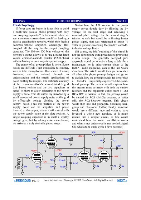
Fresh Topology<br />
If fewer caps are better, is it possible to build<br />
a multi-tube passive phono preamp with only<br />
one coupling capacitor In the circuit below we<br />
see a constant-current-draw amplifier feeding a<br />
passive equalization network, which then feeds a<br />
common-cathode amplifier, amazingly DCcoupled<br />
all the way to the output coupling<br />
capacitor. The 100-volt DC bias voltage on the<br />
network's output allows us to use a rather large<br />
valued common-cathode resistor (5200-ohms)<br />
without having to use a negative power supply.<br />
The enemy of all preamplifiers is noise. Some<br />
noises are difficult if not impossible to counter,<br />
such as tube microphonics. One source of noise,<br />
however, can be reduced through an<br />
understanding and the careful applications of<br />
noise mulling techniques. The elaborate circuitry<br />
at the common-cathode's second triode's grid<br />
(the 1-meg resistor and the two capacitors in<br />
series) is there to allow canceling of the power<br />
supply’s noise from its output by introducing a<br />
small amount of power supply noise at this grid<br />
by effectively voltage dividing the power<br />
supply’ noise. Thus this portion of the power<br />
supply noise can be amplified and phase<br />
inverted at the output, where it will cancel with<br />
the power supply noise at the plate resistor. A<br />
single coupling capacitor is in itself a worthy<br />
enough goal, but by adding noise cancellation,<br />
we arrive at a truly desirable phono stage.<br />
Notice how the 3.3k resistor in the power<br />
supply serves double duty by filtering the B+<br />
voltage for the first stage and achieving a<br />
matched plate voltage for the second stage’s<br />
triodes. A safe bet would be a floating heater<br />
power supply that was referenced to about 70<br />
volts to prevent exceeding the triode’s cathodeto-heater<br />
voltage limits.<br />
(Of course, my brief outlining of this circuit is<br />
not the correct tube-guru procedure to promoting<br />
a new design. The generally accepted guru<br />
approach would be to write a long article for a<br />
mainstream—or is minor-stream closer to the<br />
truth—audio magazine, such as the late Sound<br />
Practices. The article would then go on to slam<br />
all other tube phono preamp designs and go on<br />
to explain how the preamp sounds far better than<br />
a friend’s supremely-expensive-tube-namebrand<br />
preamp. The article would explain how<br />
the preamp must be made with both the carbon<br />
resistors and the capacitors culled from a 1961<br />
RCA BW television; in fact, the preamp would<br />
be named the RCA Uni-Cap preamp, or better<br />
still, the RCA-Unicorn preamp. This circuit<br />
would then live and propagate, becoming usergroup<br />
and chat-room fodder; finally, someone<br />
would use a different tube and claim to have<br />
invented a whole new topology or it might<br />
mutate into a simpler circuit, as few would<br />
understand how the noise cancellation works<br />
and what is not understood is not needed; right<br />
Oh, what a tube-audio cynic I have become.)<br />
3.3k<br />
+300V<br />
10k<br />
300<br />
100µF<br />
+200V<br />
10k<br />
C1<br />
+100V<br />
6DJ8<br />
+102V<br />
+200V<br />
.22µF<br />
300<br />
75k<br />
300<br />
1M<br />
+102V<br />
47k<br />
6DJ8<br />
1µF<br />
+2V<br />
10k<br />
100<br />
.029µF<br />
10.6k<br />
.01µF<br />
6DJ8<br />
+104V 6DJ8<br />
5.2k<br />
C2 1M<br />
< PREVIOUS Pg. 10<br />
www.tubecad.com Copyright © 2002 GlassWare All Rights Reserved NEXT >


