

RIAA Preamps Part 2 - Tube CAD Journal
RIAA Preamps Part 2 - Tube CAD Journal
RIAA Preamps Part 2 - Tube CAD Journal

Create successful ePaper yourself
Turn your PDF publications into a flip-book with our unique Google optimized e-Paper software.
+200V<br />
10k<br />
300<br />
10k<br />
300<br />
300<br />
+100V<br />
6DJ8<br />
+102V<br />
98.7k<br />
.1µF<br />
300<br />
+100V<br />
6DJ8<br />
+102V<br />
8.1k<br />
.47µF<br />
47k<br />
6DJ8 +2V<br />
1µF<br />
10k<br />
100<br />
.0318µF<br />
10k<br />
1M<br />
6DJ8 +2V<br />
1µF<br />
10k<br />
100<br />
.01µF<br />
1M<br />
100k<br />
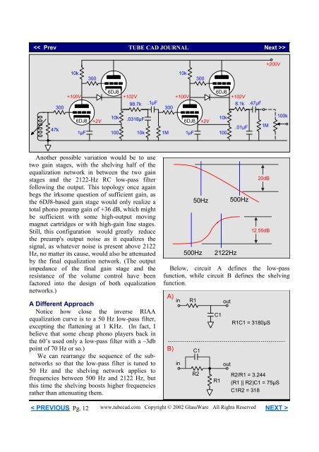
Another possible variation would be to use<br />
two gain stages, with the shelving half of the<br />
equalization network in between the two gain<br />
stages and the 2122-Hz RC low-pass filter<br />
following the output. This topology once again<br />
begs the irksome question of sufficient gain, as<br />
the 6DJ8-based gain stage would only realize a<br />
total phono preamp gain of +36 dB, which might<br />
be sufficient with some high-output moving<br />
magnet cartridges or with high-gain line stages.<br />
Still, this configuration would greatly reduce<br />
the preamp's output noise as it equalizes the<br />
signal, as whatever noise is present above 2122<br />
Hz, no matter its cause, would also be attenuated<br />
by the final equalization network. (The output<br />
impedance of the final gain stage and the<br />
resistance of the volume control have been<br />
factored into the design of both equalization<br />
networks.)<br />
A Different Approach<br />
Notice how close the inverse <strong>RIAA</strong><br />
equalization curve is to a 50 Hz low-pass filter,<br />
excepting the flattening at 1 KHz. (In fact, I<br />
believe that some cheap phono players back in<br />
the 60’s used only a low-pass filter with a –3db<br />
point of 70 Hz or so.)<br />
We can rearrange the sequence of the subnetworks<br />
so that the low-pass filter is tuned to<br />
50 Hz and the shelving network applies to<br />
frequencies between 500 Hz and 2122 Hz, but<br />
this time the shelving boosts higher frequencies<br />
rather than attenuating them.<br />
50Hz<br />
500Hz<br />
2122Hz<br />
500Hz<br />
20dB<br />
12.55dB<br />
Below, circuit A defines the low-pass<br />
function, while circuit B defines the shelving<br />
function.<br />
A)<br />
in<br />
B)<br />
in<br />
R1<br />
C1<br />
R2<br />
C1<br />
R1<br />
out<br />
out<br />
R1C1 = 3180µS<br />
R2/R1 = 3.244<br />
(R1 || R2)C1 = 75µS<br />
C1R2 = 318<br />
< PREVIOUS Pg. 12<br />
www.tubecad.com Copyright © 2002 GlassWare All Rights Reserved NEXT >


