Garage Door Operator Model MotorLift 5500 - Chamberlain
Garage Door Operator Model MotorLift 5500 - Chamberlain
Garage Door Operator Model MotorLift 5500 - Chamberlain

Create successful ePaper yourself
Turn your PDF publications into a flip-book with our unique Google optimized e-Paper software.
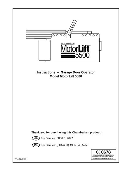
Instructions – <strong>Garage</strong> <strong>Door</strong> <strong>Operator</strong><br />
<strong>Model</strong> <strong>MotorLift</strong> <strong>5500</strong><br />
Thank you for purchasing this <strong>Chamberlain</strong> product.<br />
GB<br />
IRL<br />
For Service: 0800 317847<br />
For Service: (0044) (0) 1935 848 525<br />
114A2421D
GARAGE DOOR OPENER WARRANTY<br />
<strong>Chamberlain</strong> GmbH warrants to the first retail purchaser of this product that the product<br />
shall be free from any defect in materials and/or workmanship for a period of 60 full<br />
months (5 years) from the date of purchase. Upon receipt of the product, the first retail purchaser<br />
is under obligation to check the product for any visible defects.<br />
Conditions: The warranty is strictly limited to the reparation or replacement<br />
of the parts of this product which are found to be defective and does not cover the costs<br />
or risks of transportation of the defective parts or product.<br />
This warranty does not cover non-defect damage caused by unreasonable use (including<br />
use not in complete accordance with <strong>Chamberlain</strong>’s instructions for installation, operation<br />
and care; failure to provide necessary maintenance and adjustment; or any adaptations of<br />
or alterations to the products), labor charges for dismantling or reinstalling of a repaired or<br />
replaced unit or replacement batteries.<br />
A product under warranty which is determined to be defective in materials and/or workmanship<br />
will be repaired or replaced (at <strong>Chamberlain</strong>'s option) at no cost to the owner for the repair<br />
and/or replacement parts and/or product. Defective parts will be repaired or replaced with<br />
new or factory rebuilt parts at <strong>Chamberlain</strong>'s option.<br />
If, during the warranty period, the product appears as though it may be defective, contact<br />
your original place of purchase.<br />
This warranty does not affect the purchaser’s statutory rights under applicable national legislation<br />
in force nor the purchaser’s rights against the retailer arising from their sales/purchase<br />
contract. In the absence of applicable national or EU legislation, this warranty will<br />
be the purchaser’s sole and exclusive remedy, and neither <strong>Chamberlain</strong> nor its affiliates<br />
or distributors shall be liable for any incidental or consequential damages for any express<br />
or implied warranty relating to this product.<br />
No representative or person is authorized to assume for <strong>Chamberlain</strong> any other liability in<br />
connection with the sale of this product.<br />
Declaration of Conformity<br />
Automatic <strong>Garage</strong> <strong>Door</strong> Opener ..............................................<strong>Model</strong> No. ML<strong>5500</strong><br />
is in conformity to the applicable<br />
sections of Standards.................................EN 300 220-3, EN55014, EN61000-3,<br />
....................................................................................ETS 300 683 & EN60335-1<br />
per the provisions & all amendments<br />
of the EU Directives .....................................1999/5/EC, 73/23/EEC, 89/336/EEC<br />
Declaration of Incorporation<br />
Automatic <strong>Garage</strong> <strong>Door</strong> Opener <strong>Model</strong> No. ML<strong>5500</strong>, when installed and<br />
maintained according to all the Manufacturer’s instructions in combination<br />
with a <strong>Garage</strong> <strong>Door</strong>, which has also been installed and maintained according<br />
to all the Manufacturer’s instructions, meets the provisions of EU<br />
Directive 89/392/EEC and all amendments.<br />
I, the undersigned, hereby declare that the equipment<br />
specified above and any accessory listed in the manual<br />
conforms to the above Directives and Standards.<br />
THE CHAMBERLAIN GROUP, INC.<br />
Elmhurst, IL 60126<br />
USA<br />
May, 2003<br />
Barbara P. Kelkhoff<br />
Manager, Reg. Affairs<br />
© 2003, <strong>Chamberlain</strong> GmbH<br />
114A2421D All rights reserved Printed in Mexico
START BY READING THESE IMPORTANT SAFETY RULES<br />
These safety alert symbols mean Caution – a personal safety or property damage instruction. Read these instructions carefully.<br />
This garage door opener is designed and tested to offer reasonable safe service provided it is installed and operated in strict accordance<br />
with the following safety rules.<br />
Failure to comply with the following instructions may result in serious personal injury or property damage.<br />
Caution: If your garage has no service entrance door, <strong>Model</strong> 1702EML Outside Quick Release must be installed. This accessory allows manual<br />
operation of the garage door from outside in case of power failure.<br />
Keep garage door balanced. Sticking or binding doors must<br />
be repaired. <strong>Garage</strong> doors, door springs, cables, pulleys,<br />
brackets and their hardware are under extreme tension and<br />
can cause serious personal injury. Do not attempt to loosen,<br />
move or adjust them. Call for garage door service.<br />
Do not wear rings, watches or loose clothing while installing<br />
or servicing a garage door opener.<br />
To avoid serious personal injury from entanglement, remove<br />
all ropes connected to the garage door before installing the<br />
door opener.<br />
Installation and wiring must be in compliance with your local<br />
building and electrical codes. Connect the power supply<br />
cord only to properly earthed mains.<br />
Lightweight doors or fiberglass, aluminum or steel must<br />
be substantially reinforced to avoid door damage. (See<br />
page 4.) The best solution is to check with your garage door<br />
manufacturer for an opener installation reinforcement kit.<br />
The safety reverse system test is very important. Your<br />
garage door MUST reverse on contact with a 50mm (2")<br />
obstacle placed on the floor. Failure to properly adjust the<br />
opener may result in serious personal injury from a closing<br />
garage door. Repeat the test once a month and make any<br />
needed adjustments.<br />
This unit should not be installed in a damp or wet space.<br />
<strong>Door</strong> must not extend over public byway during operation.<br />
The force, as measured on the closing edge of the door,<br />
should not exceed 150 N (15kg). If the closing force is<br />
adjusted to more than 150 N, the Protector System must<br />
be installed. Do not use the force adjustments to<br />
compensate for a binding or sticking garage door.<br />
Excessive force will interfere with the proper operation of the<br />
Safety Reverse System or damage the garage door.<br />
Fasten the caution label adjacent to the lighted door control<br />
button as a reminder of safe operating procedures.<br />
Disengage all existing garage door locks to avoid damage<br />
to garage door.<br />
Install the lighted door control button (or any additional push<br />
buttons) in a location where the garage door is visible, but<br />
out of the reach of children. Do not allow children to<br />
operate push button(s) or remote control(s). Serious<br />
personal injury from a closing garage door may result from<br />
misuse of the opener.<br />
Activate opener only when the door is in full view, free of<br />
obstructions and opener is properly adjusted. No one<br />
should enter or leave the garage while the door is in<br />
motion. Do not allow children to play near the door.<br />
Use manual release only to disengage the trolley and, if<br />
possible, only when the door is closed. Do not use the red<br />
handle to pull the door open or closed.<br />
Disconnect electric power to the garage door opener<br />
before making repairs or removing covers.<br />
CONTENTS<br />
SAFETY RULES: Page 1<br />
DOOR TYPES: Page 1 – Illustration<br />
TOOLS REQUIRED: Illustration 2<br />
HARDWARE PROVIDED:<br />
Page 1 – Illustration 3<br />
BEFORE YOU BEGIN: Page 2<br />
COMPLETED INSTALLATION:<br />
Page 2 – Illustration 4<br />
ASSEMBLY:<br />
Page 2 – Illustrations 5 - 8<br />
1<br />
INSTALLATION:<br />
Pages 2-3 – Illustrations 9 - 18<br />
PROGRAMMING THE CODE:<br />
Page 4 – Illustration 19<br />
ADJUSTMENT:<br />
Page 4 – Illustrations 20 - 22<br />
INSTALL THE PROTECTOR: (Optional):<br />
Page 4 – Illustration 23<br />
OPERATION OF YOUR OPENER: Page 5<br />
CARE OF YOUR OPENER: Page 5<br />
MAINTENANCE OF YOUR OPENER: Page 5<br />
PROBLEMS: Pages 5-6<br />
SPECIAL FEATURE OF THE ML<strong>5500</strong>:<br />
Page 6 – Illustration 24<br />
ACCESSORIES:<br />
Page 6 – Illustration 25<br />
SPECIFICATIONS: Page 6<br />
REPLACEMENT PARTS:<br />
Illustrations 26 - 27<br />
DOOR TYPES<br />
1<br />
HARDWARE PROVIDED 3<br />
A. One-Piece <strong>Door</strong> with Horizontal Track Only<br />
B. One-Piece <strong>Door</strong> with Horizontal and Vertical Track:<br />
Special door arm (F, The <strong>Chamberlain</strong> Arm) required. See your<br />
dealer.<br />
C. Sectional <strong>Door</strong> with Curved Track:<br />
See 18 B – Connect <strong>Door</strong> Arm.<br />
D. Double-wing door: Special door arm required. See your dealer.<br />
E. Canopy door:<br />
Special door arm (F, The <strong>Chamberlain</strong> Arm) required. See your<br />
dealer.<br />
Assembly Hardware:<br />
(1) Bolts (8)<br />
(2) Hex Screws (4)<br />
(3) Lock Nuts (12)<br />
(4) Coupling<br />
Installation Hardware:<br />
(5) Carriage Bolts (2)<br />
(6) Wood Screws (4)<br />
(7) Screws (2)<br />
(8) Clevis Pins (3)<br />
(9) Hex Screws (4)<br />
(10) Rope<br />
(11) Handle<br />
(12) Insulated Staples<br />
(13) Anchors (2)<br />
(14) Lock Washers (6)<br />
(15) Nuts (6)<br />
(16) Ring Fasteners (3)<br />
(17) 8mm Anchors (4)<br />
(18) Sheet Metal Screws (2)<br />
114A2421D<br />
1-GB
BEFORE YOU BEGIN:<br />
1. Look at the wall or ceiling above the garage door. The door/header<br />
bracket must be securely fastened to structural supports.<br />
2. Do you have a finished ceiling in your garage If so, a support bracket<br />
and additional fastening hardware (not supplied) may be required.<br />
3. Depending on your door's construction, you might need a special door<br />
arm. See your dealer.<br />
4. Do you have an access door in addition to the garage door If not,<br />
<strong>Model</strong> 1702EML Outside Quick Release Accessory is required.<br />
COMPLETED INSTALLATION<br />
As you proceed with the assembly, installation and adjustment<br />
proceedures in this manual, you may find it helpful to refer back to<br />
this illustration of a completed installation.<br />
(1) Rail Brackets (7) Light Lens<br />
(2) Trolley (8) Manual Release Rope & Handle<br />
(3) Rail (9) Curved <strong>Door</strong> Arm<br />
(4) Hanging Bracket (10) Straight <strong>Door</strong> Arm<br />
(5) Power Cord (11) <strong>Door</strong>/Header Brackets<br />
(6) Opener (12) Trolley Release Arm<br />
ASSEMBLY SECTION 5 - 8<br />
ASSEMBLE THE RAIL 5<br />
1. (Illustration 5A) Turn the opened rail carton upside down, emptying its<br />
contents onto a level work surface.<br />
2. Unfold the rails, taking care to avoid kinking the screw rod joints.<br />
3. (Illustration 5B) Rotate the rail sections so that the flat side is down and<br />
the screw side is up for all three lengths. Keep it clean and free of debris<br />
while you are working.<br />
CAUTION: During assembly, avoid pulling the rail section housing the<br />
trolley rack (1) away from the screw rod. The rack is factory set about<br />
230mm (9") from the end of the screw rod to the center of the rack.<br />
If the plastic liner slides part way out during assembly, simply push it back in.<br />
4. (Illustration 5C) Beginning with the sprocket end (2), straighten the two<br />
rail sections so that the screw rod is in a straight line at the joint. (Avoid<br />
handling the joints, which may have sharp edges.)<br />
5. Carefully slide the pins (3) at the top edge of the rail into the openings<br />
(4) on the adjacent rail. It is essential that the rail assembly be on a<br />
level surface to achieve proper alignment and to avoid damage to<br />
the pins.<br />
6. Insert two bolts (5) through the center holes of a brace (6), and place its<br />
open length against the rail at this joint, aligning the holes as shown.<br />
Position another brace on the opposite side of the rail over the bolts, add<br />
lock nuts (7), and hand tighten. Insert two additional bolts and hand<br />
tighten.<br />
7. Keeping the rail straight and on a level surface, grasp the screw rods on<br />
each side of the remaining joint and pivot into a straight line. Repeat<br />
steps 5 and 6.<br />
8. With an 11mm wrench, tighten bolts til snug. Work from the center holes<br />
to those further from the joints. Do not overtighten.<br />
FASTEN THE RAIL TO THE OPENER 6<br />
Align the rail assembly (1) with the opener (2). Slip the coupling (3) over<br />
the rail sprocket (4). Slide the rail through the opener bracket (5) until the<br />
coupling fits securely over the opener sprocket (6). Align the two screw<br />
holes in the rail with those in the opener bracket. Insert two hex screws (7)<br />
and lock nuts (8). Tighten securely.<br />
INSTALL THE TROLLEY 7<br />
Slide the trolley (1) onto and along the bottom of the rail until it snaps firmly<br />
in place. Be certain to install it facing correctly: the trolley release arm<br />
must be horizontal (lock position), with its arrow pointed away from<br />
the opener.<br />
4<br />
ATTACH THE RAIL BRACKETS 8<br />
Align rail brackets (1) with end of rail assembly. Insert two hex screws (2)<br />
and lock nuts (3). Tighten securely.<br />
ASSEMBLY OF YOUR OPENER IS NOW COMPLETE.<br />
INSTALLATION SECTION 9 - 18<br />
Wear protective goggles when working overhead to protect your eyes<br />
from injury.<br />
Disengage all existing garage door locks to avoid damage to the<br />
garage door.<br />
To avoid serious personal injury from entanglement, remove all ropes<br />
connected to the garage door before installing the opener.<br />
Installation of this product shall comply with ZH1/494, VDE 0700 Part 238,<br />
and VDE 0700 Part 1.<br />
It is recommended that the opener be installed 2,1m (7 feet) or more above<br />
the floor where space permits.<br />
POSITION THE HEADER BRACKET 9<br />
The header bracket must be rigidly fastened to a structural support of<br />
the garage. Reinforce the wall or ceiling with a 40mm (1-1/2") board if<br />
necessary. Failure to comply may result in improper operation of<br />
safety reverse system.<br />
You can attach the header bracket either to the header wall (1) or to the<br />
ceiling (3). Follow the instructions which will work best for your particular<br />
requirements.<br />
With the door closed, mark the vertical centerline (2) of the garage door.<br />
Extend line onto header wall above the door.<br />
Open door to highest point of travel. Draw an intersecting horizontal line on<br />
header wall 75mm (3") above high point to provide travel clearance for top<br />
edge of door.<br />
INSTALL THE HEADER BRACKET 10<br />
A. Wall Mount: Center the bracket (2) on the vertical guideline (1) with the<br />
bottom edge of the bracket on the horizontal line (6) (with the arrow<br />
pointing toward the ceiling).<br />
Mark either set of bracket holes (4 or 5). Do not use the holes<br />
designated for ceiling mount. Drill 4,5mm (3/16") pilot holes and fasten<br />
the bracket with wood screws (3).<br />
B. Ceiling Mount: Extend vertical guideline (1) onto the ceiling. Center the<br />
bracket (2) on the vertical mark no more than 150mm (6") from the wall.<br />
Make sure the arrow is pointing toward the wall.<br />
Mark holes designated for ceiling mount only (4). Drill 4,5mm (3/16") pilot<br />
holes and fasten the bracket with wood screws (3). For concrete ceiling<br />
mount, use concrete anchors (7) provided.<br />
ATTACH RAIL TO HEADER BRACKET 11<br />
Position opener on garage floor below the header bracket. Use packing<br />
material to protect the cover.<br />
Note: To enable the rail to clear sectional door springs, it may be<br />
necessary to lift opener onto a temporary support.<br />
The opener must either be secured to a support or held firmly in place by<br />
another person.<br />
Raise rail until rail brackets and header bracket come together. Join with<br />
clevis pin (1). Insert ring fastener (2) to secure.<br />
POSITION THE OPENER 12<br />
Note: A 25mm (1") board (1) is convenient for setting an ideal door-to-rail<br />
distance (unless headroom is not sufficient).<br />
Raise the opener onto a stepladder. Open garage door. Place a 25mm<br />
(1") board (1) laid flat on the top section of door near the centerline as<br />
shown. Rest the rail on the board.<br />
If the raised door hits the trolley, pull down on the trolley release arm to<br />
disconnect the inner and outer trolley sections. The trolley can remain<br />
disconnected until connecting door arm to trolley is completed.<br />
114A2421D<br />
2-GB
HANG THE OPENER 13<br />
The opener must be securely fastened to a structural support of the<br />
garage. Attach the hanging brackets toward the front of the opener as<br />
shown (1).<br />
Three representative installations are shown. Yours may be different.<br />
Hanging brackets (2) should be angled (Figure A) to provide rigid support.<br />
On finished ceilings, (Figure B) attach a sturdy metal bracket (not<br />
supplied) (5) to a structural support before installing the opener. For<br />
concrete ceiling mount, (Figure C), use concrete anchors (6) provided.<br />
On each side of opener measure the distance from the opener to the<br />
structural support (or ceiling).<br />
Cut both pieces of the hanging bracket to required lengths. Flatten one end<br />
of each bracket and bend or twist to fit the fastening angles. Do not bend<br />
at the bracket holes. Drill 4,5mm (3/16") pilot holes in the structural<br />
supports (or ceiling). Attach flattened ends of brackets to supports with<br />
wood screws (3).<br />
Lift opener and fasten to hanging brackets with screw, lock washer and nut<br />
(4). Check to make sure rail is centered over the door. REMOVE<br />
25mm (1") board. Operate door manually. If door hits the rail, raise header<br />
bracket.<br />
ATTACH MANUAL RELEASE ROPE & HANDLE 14<br />
Thread one end of rope (1) through hole in top of red handle so "NOTICE"<br />
reads right side up as shown (3). Secure with an overhand knot (2). Knot<br />
should be at least 25mm (1") from end of the rope to prevent slipping.<br />
Thread other end of rope through hole in release arm of the outer trolley<br />
(4). Adjust rope length so that handle is 1,8m (6 feet) above the floor.<br />
Secure with an overhand knot.<br />
Note: If it is necessary to cut rope, heat seal cut end with a match or<br />
lighter to prevent fraying.<br />
CONNECT ELECTRIC POWER<br />
TO AVOID INSTALLATION DIFFICULTIES, DO NOT RUN THE GARAGE<br />
DOOR OPENER UNTIL INSTRUCTED TO DO SO.<br />
Connect the opener to a mains which is properly EARTHED according<br />
to the wiring instruction tag attached to power supply cord (and as<br />
specified by local code).<br />
Connect the door opener only to an outlet controlled by a double pole<br />
switch.<br />
INSTALL THE LIGHTED DOOR CONTROL BUTTON 15<br />
Locate push buttons where the garage door is visible, away from<br />
door and door hardware and out of the reach of children.<br />
Serious personal injury from a moving garage door may result from<br />
misuse of opener. Do not allow children to operate the lighted door<br />
control button or remote control transmitter.<br />
Fasten the caution label on the wall near the lighted door control<br />
button as a reminder of safe operating procedures.<br />
There are 2 screw terminals (1) on the back of the lighted door control<br />
button (2). Strip about 6mm (1/4") of insulation from bell wire (4). Separate<br />
wires enough to connect the white/red wire to terminal screw 1 and the<br />
white wire to terminal screw 2.<br />
Fasten the lighted door control button to an inside garage wall with sheet<br />
metal screws (3) provided. Drill 4mm (5/32") holes and use anchors (6) if<br />
installing into drywall or concrete. A convenient place is beside the service<br />
door and out of reach of children.<br />
Run the bell wire up the wall and across the ceiling to the garage door<br />
opener. Use insulated staples (5) to secure wire. The receiver terminal<br />
screws (7) are located on the back panel of the opener. Connect the bell wire<br />
to the terminal screws as follows: white/red to 1 and white to 2.<br />
INSTALL THE LIGHT AND LENS 16<br />
Install a 40 watt maximum (230V/E27) light bulb (1) in the socket as<br />
shown. The light will turn on and remain lit for 4-1/2 minutes when power is<br />
connected. After 4-1/2 minutes it will turn off.<br />
Replace burned out bulbs with rough service light bulbs (230V/W40/E27).<br />
Apply slight pressure on sides of the lens (2) and slide tabs (3) into slots<br />
(4) in the end panel. Reverse the procedure to remove the lens.<br />
FASTEN DOOR BRACKET 17<br />
If yours is a canopy or dual-track style garage door, a door arm conversion<br />
kit is required. Follow the installation instructions included with the<br />
replacement door arm. Exercise care in removing and assembling arm<br />
conversion kit. Keep fingers away from the sliding parts.<br />
NOTE: Horizontal and vertical reinforcement is needed for lightweight<br />
garage doors.<br />
Sectional and One-Piece <strong>Door</strong> Installation Procedure:<br />
1. Center bracket (1) at the top of inside face of door as shown. Mark<br />
holes.<br />
2. A. Wooden doors<br />
Drill 8mm (5/16") holes and fasten the door bracket with nut,<br />
lock washer, and carriage bolt (2).<br />
B. Sheet metal doors<br />
Fasten with sheet metal screws (3).<br />
C. One-piece door optional<br />
Fasten with sheet metal screws (3).<br />
CONNECT DOOR ARM TO TROLLEY 18<br />
NOTE: For one-piece doors, do not connect door arm to trolley before<br />
adjusting limits. Failure to follow instructions may result in damage to<br />
door. See below.<br />
Sectional <strong>Door</strong> Installation: Note door arm configuration in Figure B.<br />
One-Piece <strong>Door</strong> Installation: Procedure (Figure A).<br />
Connect straight door arm (1) and curved door arm sections (2) to obtain<br />
the longest possible length with hardware (3, 4 & 5). With door closed,<br />
connect straight door arm section to door bracket with a clevis pin (6).<br />
Secure with a ring fastener (7).<br />
Before connecting door arm to trolley, adjust travel limits. Limit<br />
adjustment screws are located on side panel.<br />
Open <strong>Door</strong> Adjustment: Decrease up limit. Turn up limit adjustment<br />
screw counterclockwise 5-1/2 turns.<br />
Press door control button. Trolley will travel to full open position (8).<br />
Manually raise door to open position (parallel to floor) and lift door arm (9)<br />
to trolley. The arm should touch trolley just in back of door arm connector<br />
hole (10) as shown in solid line drawing. Increase up limit if necessary.<br />
One full turn equals 5cm (2") of door travel.<br />
Closed <strong>Door</strong> Adjustment: Decrease down limit. Turn down limit<br />
adjustment screw clockwise 5 complete turns.<br />
Press door control button. Trolley will travel to full closed position (11).<br />
Manually close door and lift door arm (12) to trolley. The arm should touch<br />
trolley just ahead of door arm connector hole (13) as shown in dotted line<br />
drawing. Decrease down limit if necessary. One full turn equals 5cm (2") of<br />
door travel.<br />
Connect <strong>Door</strong> Arm to Trolley: With door closed, connect curved arm to<br />
trolley with remaining clevis pin. Secure with ring fastener. Note: Lift door<br />
slightly to make connection if necessary.<br />
Run opener through a complete travel cycle. If door has a slight<br />
"backward" slant in full open position, decrease up limits until door is<br />
parallel to floor.<br />
OPERATION OF THE LIGHTED DOOR CONTROL BUTTON<br />
Press to open or close the door. Press again to reverse the door during the<br />
closing cycle or to stop the door during opening cycle.<br />
114A2421D<br />
3-GB
PROGRAM YOUR OPENER & REMOTE 19<br />
Activate the opener only when door is in full view, free of obstruction<br />
and properly adjusted. No one should enter or leave garage while<br />
door is in motion. Do not allow children to operate push button(s) or<br />
remote(s). Do not allow children to play near the door.<br />
Your garage door opener receiver and remote control transmitter are set to<br />
a matching code. If you purchase additional remote controls, the garage<br />
door opener must be programmed to accept the new remote code.<br />
Program the Receiver to Match Additional Remote Control Codes<br />
1. Press and hold the remote control push button (1).<br />
2. Press and release the "Smart" button (2) on the back panel of the<br />
opener. The opener light will flash once.<br />
3. Release the remote push button.<br />
Now the opener will operate when the remote control push button is<br />
pressed.<br />
If you release the remote control push button before the opener lights<br />
flash, the opener will not accept the code.<br />
To Erase all Remote Control Codes<br />
• Press and hold the "Smart" button on the opener panel until the indicator<br />
light turns off (about 6 seconds). All the codes the opener has learned<br />
will be erased.<br />
• To reprogram, repeat Steps 1 – 3 for each remote control in use.<br />
ADJUSTMENT SECTION 20 - 22<br />
LIMIT ADJUSTMENT 20<br />
Run the opener through a complete travel cycle. Limit adjustments are<br />
not necessary when the door opens and closes completely and doesn't<br />
reverse unintentionally in the fully closed position.<br />
Situations requiring limit adjustment are listed below. Run the opener<br />
through a complete travel cycle after each adjustment.<br />
NOTE: Repeated operation of the opener during adjustment procedures<br />
may cause motor to overheat and shut off. Allow a 15 minute cooling<br />
period after 5 continuous operations of the opener.<br />
Read the following carefully before proceeding to Force Adjustment. Use a<br />
screwdriver to make limit adjustments.<br />
If <strong>Door</strong> Doesn't Open Completely but Opens at Least 1,5m (5 feet):<br />
Increase up travel. Turn the up limit adjustment screw (1) clockwise. One<br />
turn equals 5cm (2") of travel.<br />
If door does not open at least 1,5m (5 feet): Adjust up (open) force.<br />
See Force Adjustment.<br />
If <strong>Door</strong> Doesn't Close Completely: Increase down travel. Turn down<br />
limit adjustment screw (2) counterclockwise. One turn equals 5cm (2") of<br />
travel. If the door still will not close completely, lengthen the door arm. If it<br />
still will not close completely, lower the header bracket.<br />
If Opener Reverses in Fully Closed Position: Decrease down travel.<br />
Turn down limit adjustment screw (2) clockwise. One turn equals 5cm (2")<br />
of travel.<br />
If <strong>Door</strong> Reverses when Closing and there is no Interference to Travel<br />
Cycle: Test door for binding. Pull manual release handle. Manually open<br />
and close door. If door is binding, call a door serviceman. If door is not<br />
binding or unbalanced, adjust down (close) force.<br />
FORCE ADJUSTMENT 21<br />
The force, as measured on the closing edge of the door, should not<br />
exceed 150 N (15kg). If the closing force is adjusted to more than<br />
150 N, the Protector System must be installed.<br />
Do not use force adjustments to compensate for a binding or sticking<br />
garage door. Excessive force will interfere with proper operation of<br />
safety reverse system or damage garage door.<br />
Force Adjustment Controls (1 & 2) are located on the back panel of the<br />
opener.<br />
If the force adjustments are set too light, door travel may be interrupted by<br />
nuisance reversals in down direction and stops in up direction. Weather<br />
conditions can affect the door movement, occasional adjustment may be<br />
needed.<br />
Maximum force adjustment range is 260 degrees, about 3/4 of a complete<br />
turn. Do not force controls beyond that point. Turn force adjustment<br />
controls with a screwdriver.<br />
Test Down (Close) Force: Grasp the door handle or door bottom when<br />
door is about halfway through down (close) travel. <strong>Door</strong> should reverse.<br />
Reversal halfway through down travel does not guarantee reversal on a<br />
50mm (2") obstruction. If the door is hard to hold or doesn't reverse,<br />
decrease down (close) force by turning the control (2) in a<br />
counterclockwise direction. Make small adjustments until door reverses<br />
normally. After each adjustment, run opener through a complete cycle.<br />
If <strong>Door</strong> Doesn't Open at Least 1,5m (5 feet): Increase up (open) force by<br />
turning the control (1) in a clockwise direction. Make small adjustments<br />
until door opens completely. Re-adjust up limit if necessary. After each<br />
adjustment, run opener through a complete travel cycle.<br />
If <strong>Door</strong> Reverses During Down (Close) Cycle: Increase down (close)<br />
force by turning the control (2) in a clockwise direction. Make small<br />
adjustments until door completes close cycle. After each adjustment, run<br />
the opener through a complete travel cycle. Do not increase the force<br />
beyond the minimum amount required to close the door.<br />
TEST THE SAFETY REVERSE SYSTEM 22<br />
The safety reverse system test is important. <strong>Garage</strong> door must<br />
reverse on contact with a 50mm (2") obstacle laid flat on the floor.<br />
Failure to properly adjust opener may result in serious personal injury<br />
from a closing garage door. Repeat test once a month and adjust as<br />
needed.<br />
Procedure: Always begin with door in fully open position. Place a 50mm<br />
(2") obstacle (1) laid flat on the floor under the garage door. Operate the<br />
door in the down direction. The door must reverse on the obstruction. If<br />
the door stops on the obstruction, it is not traveling far enough in the<br />
down direction. Increase the down limit by turning down limit adjustment<br />
screw counterclockwise 1/4 turn. Repeat test.<br />
When the door reverses on the 50mm (2") obstacle, remove the<br />
obstruction and run the opener through a complete travel cycle. <strong>Door</strong> must<br />
not reverse in closed position. If it does, adjust Limits and Force and<br />
repeat safety reverse test.<br />
INSTALL THE PROTECTOR<br />
(See accessories)<br />
The force, as measured on the closing edge of the door, should not<br />
exceed 150 N (15kg). If the closing force is adjusted to more than<br />
150 N, the Protector System must be installed.<br />
After opener has been installed and adjusted, The Protector System<br />
accessory can be installed. Instructions are included with this accessory.<br />
The Protector System provides an additional measure of safety<br />
against a small child being caught under a garage door.<br />
It uses an invisible beam which, when broken by an obstruction, causes a<br />
closing door to open and prevents an open door from closing. It is strongly<br />
recommended for homeowners with young children.<br />
23<br />
114A2421D<br />
4-GB
OPERATION OF YOUR OPENER<br />
Your opener can be activated by any of the following devices:<br />
• The Lighted <strong>Door</strong> Control Button. Hold the button down until door<br />
starts to move.<br />
• The Outside Keylock or Keyless Entry System (if you have installed<br />
either of these accessories).<br />
• The Remote Control Transmitter. Hold the push button down until the<br />
door starts to move.<br />
Opening the <strong>Door</strong> Manually:<br />
<strong>Door</strong> should be fully closed if possible. Weak or broken springs could<br />
allow an open door to fall rapidly. Property damage or serious<br />
personal injury could result.<br />
The door can be opened manually by pulling the release handle straight<br />
down (so that the trolley release arm snaps into a vertical position). To<br />
reconnect the door, pull the release handle toward the opener at a 45˚<br />
angle so that the trolley release arm is horizontal. See illustration 14.<br />
Do not use the manual release handle to pull the door open or closed.<br />
When the Opener is Activated by Remote Control or Lighted <strong>Door</strong><br />
Control Button:<br />
1. If open, the door will close. If closed, the door will open.<br />
2. If closing, the door will reverse.<br />
3. If opening, the door will stop (allowing space for entry and exit of pets<br />
and for fresh air).<br />
4. If the door has been stopped in a partially open position, it will close.<br />
5. If an obstruction is encountered while closing, the door will reverse.<br />
6. If an obstruction is encountered while opening, the door will stop.<br />
7. The optional Protector System uses an invisible beam which, when<br />
broken by an obstruction, causes a closing door to open and prevents<br />
an open door from closing. It is STRONGLY RECOMMENDED for<br />
homeowners with young children.<br />
Allow a 15 minute cooling period after 5 continuous operations of the<br />
opener.<br />
The opener light will turn on: 1. when opener is initially plugged in;<br />
2. when the power is interrupted; 3. when the opener is activated.<br />
The light turns off automatically after 4-1/2 minutes. Bulb size is 40 Watts<br />
maximum (230V, E27).<br />
CARE OF YOUR OPENER<br />
When properly installed, opener will provide high performance with a<br />
minimum of maintenance. The opener does not require additional<br />
lubrication.<br />
Limit and Force Adjustments: These adjustments must be checked and<br />
properly set when opener is installed. Only a screwdriver is<br />
required. Weather conditions may cause some minor changes in the door<br />
operation, requiring some re-adjustments, particularly during the first year<br />
of operation.<br />
Refer to the limit and force adjustments on page 4. Follow the instructions<br />
carefully and repeat the safety reverse test after any adjustment.<br />
Remote Control Transmitter: The portable remote control may be<br />
secured to a car sun visor with the clip provided. Additional remotes can be<br />
purchased at any time for use in all vehicles using garage. Refer to<br />
Accessories. The receiver must be programmed to operate with any new<br />
remote.<br />
Remote Control Battery: The lithium batteries should produce power for<br />
up to 5 years. When the light becomes dim or does not come on, replace<br />
the battery. If transmission range lessens, check the battery test light.<br />
To Change Battery: To replace batteries, use the visor clip or screwdriver<br />
blade to pry open the case. Insert batteries positive side up. To replace<br />
cover, snap shut along both sides. Do not dispose of the old battery with<br />
household waste. Take battery to a proper disposal center.<br />
MAINTENANCE OF YOUR OPENER<br />
Once a Month:<br />
• Repeat safety reverse test. Make any necessary adjustments.<br />
• Manually operate door. If it is unbalanced or binding, call for professional<br />
garage door service.<br />
• Check to be sure door opens and closes fully. Adjust Limits and/or Force<br />
if necessary.<br />
Once a Year:<br />
Oil door rollers, bearings and hinges. The opener does not require<br />
additional lubrication. Do not grease the door tracks.<br />
HAVING A PROBLEM<br />
1. Opener doesn't operate from either door control or remote:<br />
• Does the opener have electric power Plug lamp into outlet. If it doesn't<br />
light, check the fuse box or the circuit breaker. (Some outlets are<br />
controlled by a wall switch.)<br />
• Have you disengaged all door locks Review installation instruction<br />
warnings on page 1.<br />
• Is there a build-up of ice or snow under door The door may be frozen to<br />
ground. Remove any obstruction.<br />
• The garage door spring may be broken. Have it replaced.<br />
• Repeated operation may have tripped the overload protector in the motor.<br />
Wait 15 minutes. Try again.<br />
2. Opener operates from remote but not from door control:<br />
• Is door control button lit If not, remove the bell wire from the opener<br />
terminals. Short the red and white terminals by touching both terminals at<br />
the same time with a piece of wire. If the opener runs, check for a faulty<br />
wire connection at the door control, a short under the staples, or a broken<br />
wire.<br />
• Are wiring connections correct Review page 3.<br />
3. <strong>Door</strong> operates from door control but not from remote:<br />
• Check the battery test light. Replace battery if necessary.<br />
• If you have two or more remotes and only one operates, review receiver<br />
programming procedures on page 4.<br />
• Is the door control button flashing The opener receiver must<br />
re-learn the remote control code. Follow the instructions on page 4.<br />
4. Remote has short range:<br />
• Is battery installed Check battery test light. If the light is dim, change the<br />
battery.<br />
• Change the location of the remote control on the car.<br />
• A metal garage door, foil-backed insulation or metal siding will reduce the<br />
transmission range.<br />
• Make sure antenna is fully extended across ceiling towards the door.<br />
5. <strong>Door</strong> reverses for no apparent reason and opener lights don't blink:<br />
• Is something obstructing the door Pull manual release handle. Operate<br />
door manually. If it is unbalanced or binding, call for professional garage<br />
door service.<br />
• Clear any ice or snow from garage floor area where garage door closes.<br />
• Review Force Adjustment.<br />
• If door reverses in FULLY CLOSED position, decrease travel limits.<br />
Repeat safety reverse test after adjustment is complete.<br />
The need for occasional adjustment of the force and limit settings is<br />
normal. Weather conditions in particular can affect door travel.<br />
6. <strong>Door</strong> reverses for no apparent reason and opener lights blink for<br />
5 seconds after reversing:<br />
Check The Protector System (if you have installed this accessory). If the<br />
light is blinking, correct alignment.<br />
114A2421D<br />
5-GB
HAVING A PROBLEM (Continued)<br />
7. Opener noise is disturbing in living quarters of home:<br />
If operational noise is a problem because of proximity of the opener to the<br />
living quarters, Vibration Isolator Kit 41A3263 can be installed. This kit was<br />
designed to eliminate the "sounding board effect" and is easy to install.<br />
8. The garage door opens and closes by itself:<br />
• Is there a neighbor with a garage door opener using the same frequency<br />
code Change your code.<br />
• Make sure remote push button is not stuck “on.”<br />
9. <strong>Door</strong> stops but doesn't close completely:<br />
Review Travel Limits Adjustment.<br />
Repeat safety reverse test after any adjustment of door arm length,<br />
close force or down limit.<br />
10. <strong>Door</strong> opens but won't close:<br />
• Check The Protector System (if you have installed this accessory). If<br />
the light is blinking, correct alignment.<br />
• If opener lights do not blink and it is a new installation, check the down<br />
force.<br />
Repeat the safety reverse test after the adjustment is complete.<br />
11. Opener light does not turn on:<br />
Replace light bulb (40 Watts maximum, 230V, E27). Replace burned out<br />
bulbs with rough service light bulbs.<br />
12. Opener light does not turn off:<br />
There may be a defective earth at the ceiling or wall receptacle. The unit<br />
must be earthed.<br />
13. Opener strains or maximum force is needed to activate door:<br />
<strong>Door</strong> may be unbalanced or springs are broken. Close door and use<br />
manual release rope and handle to disconnect trolley. Open and close door<br />
manually. A properly balanced door will stay in any point of travel while<br />
being supported entirely by its springs. If it does not, call for professional<br />
garage door service to correct the problem. Do not increase the force to<br />
operate the opener.<br />
14. Opener motor hums briefly, then won't work:<br />
• <strong>Garage</strong> door springs are broken. SEE ABOVE.<br />
• If problem occurs on first operation of opener, door may be locked.<br />
Disable door lock.<br />
15. Opener won't activate due to power failure:<br />
• Pull manual release rope and handle straight down to disconnect trolley.<br />
<strong>Door</strong> can be opened and closed manually. When the power is restored,<br />
pull the manual release handle toward the opener at a 45˚ angle, so that<br />
the trolley release arm is horizontal. The next time the opener is<br />
activated, the trolley will reconnect.<br />
• The Outside Quick Release accessory 1702EML (if fitted) disconnects the<br />
trolley from outside the garage in case of power failure.<br />
SPECIAL FEATURE OF THE MOTORLIFT <strong>5500</strong><br />
<strong>Door</strong> within a door connection<br />
Remove cover. Locate auxiliary terminal block. Remove jumper from<br />
terminal leads 1 and 2 (not shown). Replace with magnetic contact switch<br />
leads as shown.<br />
24<br />
ACCESSORIES<br />
(1) <strong>Model</strong> 4330EML Single-Function Remote Control<br />
(2) <strong>Model</strong> 4333EML 3-Function Remote Control<br />
(3) <strong>Model</strong> 4335EML 3-Function Mini Remote Control<br />
(4) <strong>Model</strong> 845EML Multi-Function <strong>Door</strong> Control Panel<br />
(5) <strong>Model</strong> 75EML Lighted <strong>Door</strong> Control Button<br />
(6) <strong>Model</strong> 747EML Wireless Keyless Entry Keypad<br />
(7) <strong>Model</strong> 760EML Outside Keylock<br />
(8) <strong>Model</strong> 1702EML Outside Quick Release<br />
(9) <strong>Model</strong> 770EML The Protector System<br />
(10) <strong>Model</strong> 1EML <strong>Door</strong> Handle Quick Release<br />
(11) <strong>Model</strong> 34EML 2-Position Key Switch Flush Mount<br />
<strong>Model</strong> 41EML 2-Position Key Switch Surface Mount<br />
(12) <strong>Model</strong> 1703EML The <strong>Chamberlain</strong> Arm<br />
WIRING INSTRUCTIONS FOR ACCESSORIES<br />
Lighted Push Button: Protector System:<br />
To opener terminals:<br />
To opener terminals:<br />
Red-1 and White-2<br />
White-2 and Black-3<br />
Outside Keylock:<br />
Wall Control Panel:<br />
To opener terminals:<br />
To opener terminals:<br />
Red-1 and White-2<br />
Red-1 and White-2<br />
REPLACEMENT PARTS 26 - 27<br />
SPECIFICATIONS<br />
25<br />
Max. Pull Force ...........900N<br />
Watts ...........................510W<br />
Motor<br />
Type.............................Permanent split capacitor<br />
Speed ..........................1500 rpm<br />
Volts.............................230-240 Volts AC-50Hz Only<br />
Drive Mechanism<br />
Reduction ....................1.27:1<br />
Drive ............................Screw. 2 Lead worm. Aluminum rail.<br />
Length of Travel ..........Adjustable to 2,23m (7.4 feet)<br />
Travel Rate..................152mm (6 inches) per second<br />
Lamp ...........................1x230V/40W/E27 socket, on when door starts,<br />
off 4-1/2 minutes after stop.<br />
<strong>Door</strong> Linkage...............Adjustable door arm. Pull cord trolley release.<br />
Safety<br />
Personal ......................Push button and automatic reversal in down<br />
direction. Push button and automatic stop in up<br />
direction.<br />
Electronic.....................Independent up and down force adjustment screws.<br />
Electrical......................Motor overload protector and low voltage push<br />
button wiring.<br />
Limit Adjustment..........Screwdriver adjustment on side panel.<br />
Start Circuit .................Low voltage push button circuit.<br />
Dimensions<br />
Length (Overall) ..........3,1m (122 inches)<br />
Headroom Required....6cm (2.3 inches)<br />
Hanging Weight...........19 kg (41.8 lb)<br />
Receiver Memory Registers<br />
Computer Code...........12<br />
Code Switch ................1<br />
Keypad ........................1<br />
114A2421D<br />
6-GB