Instruction Manual (PDF) - ICOM Canada
Instruction Manual (PDF) - ICOM Canada
Instruction Manual (PDF) - ICOM Canada

Create successful ePaper yourself
Turn your PDF publications into a flip-book with our unique Google optimized e-Paper software.
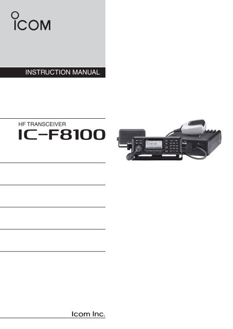
INSTRUCTION MANUAL<br />
HF TRANSCEIVER<br />
iF8100
FOREWORD<br />
Thank you for purchasing this Icom product. The IC-<br />
F8100 hf transceiver is designed and built with<br />
Icom’s state of the art technology and craftsmanship.<br />
With proper care, this product should provide you with<br />
years of trouble-free operation.<br />
We appreciate you making the IC-F8100 your radio of<br />
choice, and hope you agree with Icom’s philosophy of<br />
“technology first.” Many hours of research and development<br />
went into the design of your IC-F8100.<br />
D FEATURES<br />
❍ ALE (Automatic Link Establishment)/Selcall<br />
capability<br />
❍ Digital Signal Processor (DSP) allows flexible<br />
filter selection<br />
❍ Full-dot matrix LCD for variety of information<br />
IMPORTANT<br />
READ THIS INSTRUCTION MANUAL<br />
CAREFULLY before attempting to operate the<br />
transceiver.<br />
SAVE THIS INSTRUCTION MANUAL. This<br />
manual contains important safety and operating instructions<br />
for the IC-F8100.<br />
EXPLICIT DEFINITIONS<br />
WORD<br />
R DANGER!<br />
R WARNING!<br />
CAUTION<br />
NOTE<br />
DEFINITION<br />
Personal death, serious injury or an<br />
explosion may occur.<br />
Personal injury, fire hazard or electric<br />
shock may occur.<br />
Equipment damage may occur.<br />
Recommended for optimum use. No<br />
risk of personal injury, fire or electric<br />
shock.<br />
TABLE OF CONTENTS<br />
FOREWORD............................................................... i<br />
IMPORTANT............................................................... i<br />
EXPLICIT DEFINITIONS............................................ i<br />
TABLE OF CONTENTS.............................................. i<br />
PRECAUTIONS......................................................... ii<br />
1 PANEL DESCRIPTION...................................... 1–7<br />
■ Controller (Front panel or HM-192).................... 1<br />
■ Rear panel.......................................................... 4<br />
■ LCD screen........................................................ 5<br />
■ AD-119 Optional Junction Box........................... 7<br />
2 BASIC OPERATION........................................ 8–11<br />
■ Power ON........................................................... 8<br />
■ Selecting display mode...................................... 8<br />
■ Selecting a channel............................................ 8<br />
■ Setting audio volume.......................................... 9<br />
■ Squelch function................................................. 9<br />
■ Scan function..................................................... 9<br />
■ Mode selection................................................. 10<br />
■ Key Lock function............................................. 10<br />
■ VFO operation.................................................. 11<br />
3 RECEIVE AND TRANSMIT........................... 12–18<br />
■ Basic voice transmit/receive............................. 12<br />
■ Functions for transmit....................................... 13<br />
■ Functions for receive........................................ 15<br />
4 SELCALL/ALE OPERATION........................ 19–33<br />
■ Selcall/ALE....................................................... 19<br />
5 MENU SCREEN............................................ 34–46<br />
■ Edit Menu......................................................... 34<br />
■ User Menu........................................................ 35<br />
■ Admin Menu..................................................... 38<br />
■ CPU Reset....................................................... 46<br />
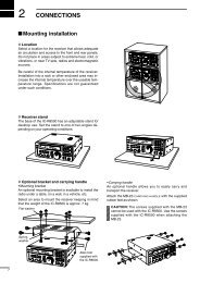
6 CONNECTION AND INSTALLATION........... 47–60<br />
■ Supplied accessories....................................... 47<br />
■ Connections..................................................... 49<br />
■ Ground connection........................................... 51<br />
■ Power source.................................................... 51<br />
■ Antenna............................................................ 52<br />
■ CFU-F8100 (Optional Cooling Fan)................. 52<br />
■ RMK-6 (Optional Separation kit)...................... 53<br />
■ HM-192 (Optional Remote control microphone)<br />
......................................................................... 55<br />
■ Mounting.......................................................... 56<br />
■ Fuse replacement............................................ 58<br />
■ Connector information for AD-119.................... 59<br />
7 SPECIFICATIONS............................................... 61<br />
8 OPTIONS............................................................. 62<br />
Versions of the IC-F8100 which display<br />
the “N33” symbol on the serial number<br />
seal, comply with Standard Australia<br />
Specification No. AS/NZS 4770: 2000.<br />
i
PRECAUTIONS<br />
R DANGER HIGH RF VOLTAGE! NEVER attach<br />
an antenna or internal antenna connector during transmission.<br />
This may result in an electrical shock or burn.<br />
R WARNING! NEVER operate the transceiver with a<br />
headset or other audio accessories at high volume levels.<br />
Hearing experts advise against continuous high volume<br />
operation. If you experience a ringing in your ears, reduce<br />
the volume or discontinue use.<br />
R WARNING! NEVER operate or touch the transceiver<br />
with wet hands. This may result in an electric<br />
shock or damage to the transceiver.<br />
R WARNING! NEVER apply AC power to the<br />
[DC13.8V] socket on the transceiver rear panel. This<br />
could cause a fire or damage the transceiver.<br />
R WARNING! NEVER apply more than 16 V DC to the<br />
[DC13.8V] socket on the transceiver rear panel, or use reverse<br />
polarity. This could cause a fire or damage the transceiver.<br />
R WARNING! NEVER let metal, wire or other objects<br />
protrude into the transceiver or into connectors on the<br />
rear panel. This may result in an electric shock.<br />
R WARNING! ALWAYS use the supplied Black and<br />
red cables with fuse holders. After connecting the fuse<br />
holders, NEVER cut the DC power cable between the<br />
DC plug and fuse holder. If an incorrect connection is<br />
made after cutting, the transceiver might be damaged.<br />
R WARNING! Immediately turn OFF the transceiver<br />
power and remove the power cable if it emits an abnormal<br />
odor, sound or smoke. Contact your Icom dealer or<br />
distributor for advice.<br />
CAUTION: NEVER change the internal settings of the<br />
transceiver. This may reduce transceiver performance<br />
and/or damage to the transceiver.<br />
In particular, incorrect settings for transmitter circuits,<br />
such as output power, idling current, and so on, might<br />
damage the expensive final devices.<br />
The transceiver warranty does not cover any problems<br />
caused by unauthorized internal adjustment.<br />
CAUTION: NEVER install the transceiver in a place<br />
without adequate ventilation. Heat dissipation may be<br />
reduced, and the transceiver may be damaged.<br />
DO NOT use or place the transceiver in direct sunlight<br />
or in areas with temperatures below –30°C (+32°F) or<br />
above +60°C (+122°F).<br />
The basic operations, transmission and reception of the<br />
transceiver are guaranteed within the specified operating<br />
temperature range. However, the LCD display may<br />
not be operate correctly, or show an indication in the<br />
case of long hours of operation, or after being placed in<br />
extremely cold areas.<br />
DO NOT use harsh solvents such as benzine or alcohol<br />
when cleaning, as they will damage the transceiver<br />
surfaces.<br />
DO NOT push the PTT switch when you don’t actually<br />
desire to transmit.<br />
DO NOT place the transceiver against walls or putting<br />
anything on top of the transceiver. This may overheat<br />
the transceiver.<br />
Always place unit in a secure place to avoid inadvertent<br />
use by children.<br />
BE CAREFUL! If you use a linear amplifier, set the<br />
transceiver’s RF output power to less than the linear<br />
amplifier’s maximum input level, otherwise, the linear<br />
amplifier will be damaged.<br />
BE CAREFUL! The transceiver will become hot when<br />
operating the transceiver continuously for long periods<br />
of time.<br />
USE only the specified microphone. Other manufacturers’<br />
microphones have different pin assignments, and<br />
connection to the IC-F8100 may damage the transceiver<br />
or microphone.<br />
During mobile operation, NEVER place the transceiver<br />
where air bag deployment may be obstructed.<br />
During mobile operation, DO NOT place the transceiver<br />
where hot or cold air blows directly onto it.<br />
During mobile operation, DO NOT operate the transceiver<br />
without running the vehicle’s engine. When the<br />
transceiver’s power is ON and your vehicle’s engine is<br />
OFF, the vehicle’s battery will soon become exhausted.<br />
Make sure the transceiver power is OFF before starting<br />
the vehicle engine. This will avoid possible damage to the<br />
transceiver by ignition voltage spikes.<br />
During maritime mobile operation, keep the transceiver<br />
and microphone as far away as possible from the<br />
magnetic navigation compass to prevent erroneous indications.<br />
Turn OFF the transceiver’s power and/or disconnect the<br />
DC power cable when you will not use the transceiver<br />
for long period of time.<br />
KEEP the transceiver away from the heavy rain, and<br />
Never immerse it in the water. The transceiver meets<br />
IP54* requirements for dust-protection and splash resistance.<br />
However, once the transceiver has been dropped, dustprotection<br />
and splash resistance cannot be guaranteed<br />
due to the fact that the transceiver may be cracked, or<br />
the waterproof seal damaged, and so on.<br />
* Only when the supplied microphone is attached.<br />
ii
1<br />
PANEL DESCRIPTION<br />
■ Controller (Front panel or HM-192)<br />
• HM-192<br />
e<br />
w !1<br />
o<br />
• Front panel<br />
r<br />
t<br />
q<br />
q<br />
w<br />
e<br />
r<br />
t y u<br />
y<br />
i<br />
u<br />
!0<br />
o<br />
i<br />
Keypad (p. 2)<br />
• Common<br />
q VOLUME KEYS [ +]/[ –](p. 9)<br />
Adjusts the audio output level.<br />
w EMERGENCY KEY [ ]<br />
NOTE: While in the VFO mode, the Emergency<br />
key cannot be used.<br />
➥ Push to enter the Emergency channel list.<br />
• Push again to return to the normal operating screen.<br />
➥ Hold down for 1 second to transmit the Selcall<br />
and RFDS call to the specified Selcall addresses<br />
in order.<br />
NOTE: The RFDS call is available for only AUS<br />
versions.<br />
e POWER KEY [ ]<br />
➥ While the transceiver’s power is OFF:<br />
Push to turn ON the transceiver power.<br />
• First, turn ON the DC power supply.<br />
➥ While the transceiver’s power is ON:<br />
Hold down for 2 second to turn OFF the power.<br />
r CALL KEY [ ]<br />
Push to enter the Call menu.<br />
• Push again to go to the next screen in the Call menu.<br />
t UP/DOWN KEYS [r]/[s]<br />
Selects the operating channel and the items in the<br />
Menu mode, and so on.<br />
y ENTER KEY [4]<br />
Push to enter or exit the selected Menu in the Menu<br />
screen.<br />
u CLEAR KEY [8]<br />
➥ Push to exit the Menu screen.<br />
➥ Push to return to the previous screen in the Call<br />
menu.<br />
i HOME/MENU KEY [HOME] [MENU](HOME)<br />
➥ Push to return to the home display.<br />
➥ Hold down for 1 second to enter the Menu<br />
screen.<br />
o FUNCTION KEYS [•]/[••]/[•••]<br />
Push to select the function that is displayed on the<br />
LCD display above each key.<br />
• The functions vary, depending on the selected menu and<br />
the operating mode.<br />
1
PANEL DESCRIPTION<br />
1<br />
• Front panel<br />
!0 MICROPHONE CONNECTOR [MIC]<br />
Connects only the microphone supplied with the<br />
transceiver.<br />
q<br />
w<br />
e<br />
NOTE: NEVER connect the HM-192 or any other<br />
microphone here.<br />
r<br />
Front view<br />
i<br />
u<br />
y<br />
t<br />
q MIC (microphone input)<br />
w MIC SW1<br />
e AF<br />
r MIC SW2<br />
t PTT<br />
y GND<br />
u GND (microphone ground)<br />
i +8 V DC output (Max. 10 mA)<br />
D Keypad<br />
➥ Inputs numbers for the Clock Setting.<br />
➥ Inputs numbers, characters or letters for the Selcall<br />
direct input.<br />
• Available characters<br />
10-key<br />
KEY INPUT KEY<br />
INPUT<br />
1 Q Z q z<br />
2 A B C a b c<br />
3 D E F d e f<br />
4 G H I g h i<br />
5 J K L j k l<br />
6 M N O m n o<br />
7 P R S p r s<br />
• HM-192<br />
!1 LOCK KEY [ ]<br />
Hold down for 1 second to set the Key lock function<br />
to ALL, NUMERIC KEY or OFF.<br />
8 T U V t u v<br />
9 W X Y w x y<br />
0<br />
(space)<br />
, . ; : ” ` ’ / ! @ # $ % ^ &<br />
* ( ) _ – + = | \ ~ < > { } [ ]<br />
Upper/Lower case letters/Numbers<br />
Quick Reference<br />
1<br />
2<br />
3<br />
4<br />
5<br />
6<br />
7<br />
8<br />
9<br />
10<br />
11<br />
12<br />
13<br />
14<br />
15<br />
16<br />
17<br />
2
1 PANEL DESCRIPTION<br />
DDKeypad (Continued)<br />
VFO KEY [VFO]<br />
Push to turn the VFO mode ON or OFF.<br />
NOTE: The VFO mode operation can be<br />
inhibited in the Admin Menu. (p. 39)<br />
GPS KEY [GPS]<br />
When a GPS receiver is connected through<br />
the optional AD-119 Junction Box or OPC-<br />
2205 Shielded control cable and valid data is<br />
received, push to turn the GPS information<br />
ON or OFF. The GPS information that can be<br />
selected are Position information, Direction<br />
and elevation.<br />
CLARIFIER KEY [CLAR]<br />
Push to turn the Clarifier function ON or<br />
OFF.<br />
NOTE: This key cannot be used when the<br />
“Clarifier” item in the User Menu is set to<br />
“OFF.” (p. 36)<br />
MUTE KEY [MUTE]<br />
Push to select the squelch types. The Call<br />
squelch, S-meter squelch (level 1 to 50),<br />
Voice squelch or squelch OFF are selectable.<br />
• The “S” icon appears when the Call squelch<br />
function is ON.<br />
• The “L” icon appears when the S-meter squelch<br />
function is ON.<br />
• The “V” icon appears when the Voice squelch<br />
function is ON.<br />
SCAN KEY [SCAN]<br />
Push to start or stop a scan.<br />
CLEAR TALK KEY [C TALK]<br />
Push to turn the Clear Talk function ON or<br />
OFF.<br />
• The “C” icon appears when the function is ON.<br />
TUNER KEY [TUNER]<br />
Push to turn the Antenna tune mode, Auto,<br />
<strong>Manual</strong> or OFF. (p. 12)<br />
• The “Auto Tune” or “<strong>Manual</strong> Tune” screen appears<br />
when the antenna tune mode is ON.<br />
• The SWR meter appears when the antenna tune<br />
mode is ON.<br />
3
PANEL DESCRIPTION<br />
1<br />
■ Rear panel<br />
u GND<br />
Quick Reference<br />
Protect plug<br />
1<br />
y ANT<br />
2<br />
t ACC2<br />
3<br />
q DC<br />
w FAN<br />
e SP<br />
r ACC1<br />
4<br />
q DC POWER CONNECTOR [DC]<br />
Accepts 13.8 V DC through a DC power cable.<br />
w FAN CONNECTOR [FAN]<br />
Connects the optional CFU-F8100 Cooling Fan.<br />
NOTE: Attach the protect plug when the optional<br />
Cooling Fan is not used.<br />
e SPEAKER JACK [SP]<br />
Connects to an external speaker such as the supplied<br />
SP-25.<br />
r ACCESSORY CONNECTOR (10 PIN) [ACC1]<br />
t ACCESSORY CONNECTOR (12 PIN) [ACC2]<br />
Connect the optional AD-119 junction box or OPC-<br />
2205 shielded control cable.<br />
Both connectors must be connected to use the AD-<br />
119 or OPC-2205.<br />
NOTE: Attach the connector caps when the optional<br />
unit or cable is not used.<br />
y ANTENNA CONNECTOR<br />
Connects a 50 Ω HF band antenna.<br />
u GROUND TERMINAL<br />
IMPORTANT! Connects a solid earth point.<br />
5<br />
6<br />
7<br />
8<br />
9<br />
10<br />
11<br />
12<br />
13<br />
14<br />
15<br />
16<br />
17<br />
4
1 PANEL DESCRIPTION<br />
■ LCD screen<br />
• Memory Channel Display<br />
• Selcall Address Display<br />
q w e r t y u q w e r t y u<br />
!0<br />
o<br />
i<br />
:<br />
!1<br />
:<br />
!0<br />
o<br />
i<br />
• ALE ID Display<br />
q w e r t y u<br />
!1<br />
!0<br />
o<br />
i<br />
q RECEIVE/TRANSMIT ICON<br />
➥ “RX” appears when signals are received or the<br />
squelch is open.<br />
➥ “TX” appears during transmit.<br />
w S-METER/TX METERS<br />
➥ Displays the receive signal strength.<br />
➥ Displays the transmit output power.<br />
Mic gain can also be displayed when the “METER<br />
TYPE” item in the Admin Menu is set to “MIC<br />
LEVEL.”<br />
e TUNE ICON<br />
Appears after the automatic antenna tuner matches<br />
the transceiver and antenna.<br />
r OPERATING MODE INDICATOR<br />
Displays the selected operating mode.<br />
• “LSB,” “USB,” “CW,” “AM,” “D1,”* “D2”* or “D3”* appears,<br />
depending on the operating mode.<br />
* When the “Modem” setting in the Admin Menu is set to<br />
“OFF,” “RTTY” appears instead. (p. 40)<br />
The D1, D2 or D3 mode can be set in the “Data mode<br />
1,” “Data mode 2” or “Data mode 3” settings in the<br />
Admin Menu. (p. 40)<br />
t MUTE ICON<br />
➥ “S” appears when the Call squelch function is selected.<br />
➥ “L” appears when the S-meter squelch is selected.<br />
➥ “V” appears when the Voice squelch is selected.<br />
y GPS ICON<br />
Appears when valid position data is received from<br />
a GPS receiver that is connected to the AD-119 or<br />
OPC-2205.<br />
u TIME INDICATOR<br />
Displays time data.<br />
i FUNCTION DISPLAY<br />
Displays the function of the function keys ([•], [••]<br />
and [•••]).<br />
o SUB READOUTS<br />
<br />
Shows the channel transmit and receive frequencies.<br />
The receive frequency is displayed on the right<br />
and the transmit frequency is displayed on the left.<br />
NOTE: The transmit frequency is not displayed<br />
when the selected channel is configured as “receive<br />
only.”<br />
<br />
Shows the Selcall ID or phone number of the call.<br />
<br />
Displays the NET ID for ALE transmissions.<br />
!0 MAIN READOUTS<br />
<br />
Displays the channel name.<br />
<br />
Shows the Selcall Address of the call.<br />
<br />
Shows the ALE ID for ALE transmission.<br />
5
PANEL DESCRIPTION<br />
1<br />
• Memory Channel Display<br />
• Selcall Address Display<br />
q w e r t y u q w e r t y u<br />
:<br />
!1<br />
:<br />
!0<br />
!0<br />
o<br />
o<br />
i<br />
i<br />
Quick Reference<br />
• ALE ID Display q w e r t y u<br />
!1<br />
!0<br />
o<br />
i<br />
!1 CALL ICON<br />
Displays the Call type icons for Selcall.<br />
• The “ ” icon appears when the Selective call is selected<br />
on the Selcall Address display.<br />
• The “ ” icon appears when the Phone call is selected<br />
on the Selcall Address display.<br />
• The “ ” icon appears when the Message call is selected<br />
on the Selcall Address display.<br />
• The “ ” icon appears when the GPS Send Position<br />
call is selected on the Selcall Address display.<br />
• The “ ” icon appears when the GPS Get Position call<br />
is selected on the Selcall Address display.<br />
• The “ ” icon appears when the Get Status call is selected<br />
on the Selcall Address display.<br />
• The “ ” icon appears when the RFDS Emergency call<br />
is selected on the Selcall Address display.<br />
• The “ ” icon appears when the Emergency call is selected<br />
on the Selcall Address display.<br />
• The “ ” icon appears when the Channel Test call is<br />
selected on the Selcall Address display.<br />
1<br />
2<br />
3<br />
4<br />
5<br />
6<br />
7<br />
8<br />
9<br />
10<br />
11<br />
12<br />
13<br />
14<br />
15<br />
16<br />
17<br />
6
1 PANEL DESCRIPTION<br />
■ AD-119 Optional Junction Box<br />
D Front Panel<br />
D Rear Panel<br />
q w e<br />
q<br />
w e r<br />
t<br />
q DATA JACK [DATA]<br />
Connects to a PC via an RS-232C cable (D-sub<br />
9-pin) for remote control in RS-232C format.<br />
w GPS CONNECTOR [GPS]<br />
Input position and UTC data in NMEA0183 ver. 2.0<br />
or 3.01 formats, such as from a GPS receiver to<br />
automatically set your position and time data.<br />
e GPIO CONNECTOR [GPIO]<br />
Connects a control cable to an optional AT-140 Antenna<br />
Tuner or AT230 Automatic Tuning Antenna.<br />
q USB CONNECTOR [USB]<br />
Connects a PC via an A-B type USB cable.<br />
w ACCESSORY CONNECTOR 2 (12 PIN) [ACC2]<br />
e ACCESSORY CONNECTOR 1 (10 PIN) [ACC1]<br />
Connect to the IC-F8100’s Accessory connectors.<br />
Both connectors must be connected to use this<br />
Junction Box.<br />
r GROUND TERMINAL<br />
IMPORTANT! Connect to a solid earth point.<br />
t EXTERNAL MODEM CONNECTOR [EXT. MODEM]<br />
Connect to an external unit such as an HF email<br />
modem or TNC (Terminal Node Controller).<br />
NOTE: This connector is not available, depending<br />
on the AD-119’s version.<br />
7
BASIC OPERATION<br />
2<br />
■ Power ON<br />
➥ Push [ ] to turn ON the Power.<br />
• Built-in Test is displayed.<br />
The BIT display can be turned OFF in Advance Menu.<br />
• Hold down [ ] for 2 seconds to turn OFF the Power.<br />
Quick Reference<br />
■ Selecting display mode<br />
➥ Push [•] one or more times to select a desired display<br />
mode.<br />
• The display toggles “Channel” ➪ “Selcall” ➪ “ALE” ➪<br />
“Channel.”<br />
■ Selecting a channel<br />
q Push [•] one or more times to select the Memory<br />
Channel display.<br />
• The display toggles through “Channel” ➪ “Selcall” ➪<br />
“ALE” ➪ “Channel.”<br />
w Push [r] or [s] to select a desired memory channel.<br />
Memory channel display<br />
Selcall Address display<br />
ALE ID display<br />
•<br />
•<br />
•<br />
1<br />
2<br />
3<br />
4<br />
5<br />
6<br />
7<br />
8<br />
9<br />
10<br />
11<br />
12<br />
13<br />
14<br />
15<br />
16<br />
17<br />
8
2 BASIC OPERATION<br />
■ Setting audio volume<br />
➥ Push [ +] or [ –] to adjust the audio level.<br />
• If the squelch is closed, push [MUTE](M) one or more<br />
times to open the squelch.<br />
• The display shows the volume level while adjusting.<br />
Minimum audio level<br />
•<br />
•<br />
•<br />
Maximum audio level<br />
■ Squelch function<br />
The squelch function detects signals with voice components<br />
and squelches (mutes) unwanted signals.<br />
This provides quiet stand-by.<br />
When you need to receive weak signals, the squelch<br />
can be turned OFF.<br />
➥ Push [MUTE](M) one or more times to select a<br />
squelch type. Selectable types are Call SQL, S-<br />
meter SQL (level 1 to 50), Voice SQL and OFF.<br />
• The S-meter squelch level can be adjusted in “Squelch<br />
Level” in the User Menu.<br />
Mute icon<br />
• Mute icon, “S,” “L,” “V” appear when the squelch function<br />
is turned ON.<br />
■ Scan function<br />
The scan function repeatedly scans programmed<br />
channels. This function is convenient to wait for calls<br />
on multiple channels.<br />
q Push [SCAN](#) to start a scan.<br />
• “Scanning” and the Scan type are displayed.<br />
[Stop]<br />
w When a signal is received, the scan pauses on<br />
that channel.<br />
e Push [Stop](••) to cancel the scan.<br />
• Pushing [SCAN](#) also cancels the scan.<br />
NOTE: The scan resume setting (the action after<br />
receiving a signal) can be changed in “Scan Resume”<br />
in the Admin Menu. (p. 41)<br />
9
BASIC OPERATION<br />
2<br />
■ Mode selection<br />
The following modes are selectable in the IC-F8100:<br />
LSB, USB, CW, AM, D1,* D2* and D3* modes.<br />
* When the “Modem” setting in the Admin Menu is set to<br />
“OFF,” “RTTY” can be selected instead. (p. 40)<br />
The D1, D2 or D3 mode can be set in the “Data mode<br />
1,” “Data mode 2” or “Data mode 3” settings in the Admin<br />
Menu. (p. 40)<br />
[Mode]<br />
■ Key Lock function<br />
To prevent accidental channel changes, or unnecessary<br />
function access, use the Key Lock function. The<br />
transceiver has two types of Key Lock functions.<br />
[]<br />
[Default] []<br />
/<br />
q Push [•] one or more times to select the Memory<br />
Channel display.<br />
• The display toggles through “Channel” ➪ “Selcall” ➪<br />
“ALE” ➪ “Channel.”<br />
w Push [Mode](••) one or more times to select the<br />
desired mode.<br />
• The selected mode icon appears at the top of the display.<br />
NOTE:<br />
• The selected mode can be used only temporary.<br />
Once changing the channel, the channel returns<br />
to the preprogrammed operating mode.<br />
• Depending on the transceiver version or preprogramming,<br />
some operating modes are not selectable<br />
or usable only receive.<br />
q Hold down [MENU](HOME) for 1 second to enter<br />
the Menu screen.<br />
w Push [r] or [s] to select the “User Menu,” and<br />
then push [4].<br />
e Push [r] or [s] to select “Key Lock.”<br />
r Push [t](•) or [u](•••) to select the Key Lock function,<br />
“ALL” or “NUMERIC KEY.”<br />
• Hold down [Default](••) for 1 second to return to the<br />
default setting.<br />
t Push [MENU](HOME) twice to return to the normal<br />
operating screen.<br />
• To turn OFF the function<br />
When you push the locked key, “Numeric Key Locked”<br />
or “All Key Locked” appears, depending on the function.<br />
Then push [Unlock](••) to turn OFF the function.<br />
Quick Reference<br />
1<br />
2<br />
3<br />
4<br />
5<br />
6<br />
7<br />
8<br />
9<br />
10<br />
11<br />
12<br />
13<br />
14<br />
15<br />
16<br />
17<br />
10
2 BASIC OPERATION<br />
■ VFO operation<br />
In the VFO mode, you can set a desired operating frequency,<br />
operating mode or split frequency function.<br />
NOTE:<br />
• The VFO mode operation can be inhibited in the<br />
Admin Menu.<br />
• While in the VFO mode, the Selcall, ALE features<br />
or the Emergency key cannot be used.<br />
/<br />
• Entering the VFO mode<br />
Push [VFO](2) to turn the VFO mode ON or OFF.<br />
[]<br />
[]<br />
[]<br />
• Frequency setting<br />
q Push [A/B](•) to select VFO A or VFO B.<br />
w Push [4] to enter the frequency setting mode.<br />
e Push [t](•) or [u](•••) to move the cursor to select<br />
the desired digit.<br />
• The cursor shows the selected digit.<br />
r Push [r] or [s] to change the frequency.<br />
t Push [4] to exit the frequency setting mode.<br />
• Turn the split frequency function<br />
q Push [A/B](•) to select VFO A or VFO B, then set<br />
the receive frequency or transmit frequency.<br />
w Push [Split](•••) to turn the split frequency function<br />
ON.<br />
• TX frequency appears below the RX frequency.<br />
e To turn OFF the split frequency function, push<br />
[Split](•••) again.<br />
11
RECEIVE AND TRANSMIT<br />
3<br />
■ Basic voice transmit/receive<br />
q First, check the following.<br />
➥ Microphone and external speaker are connected.<br />
➥ No mute icon “S,” “L” or “V” appears.<br />
• If “S,” “L” or “V” appears, push [MUTE](M) one or<br />
more times to turn OFF the mute.<br />
Mute icon<br />
r Push [TUNER](9) once or twice to enter the antenna<br />
tune mode.<br />
• The “Auto Tune” or “<strong>Manual</strong> Tune” screen appears in<br />
order.<br />
Quick Reference<br />
w Push [r] or [s] to select the desired receive channel.<br />
• The S-meter shows signal strength when signal is received.<br />
e Push [ +] or [ –] to adjust the needed audio level<br />
when receiving a signal.<br />
• If the bass or treble of the receive audio is too strong,<br />
set “Clarifier” to ON in the User Menu, and adjust to obtain<br />
clear audio. (See page 15 for the Clarifier function<br />
details.)<br />
• If the audio is distorted, select the suitable operating<br />
mode. (See page 10 for the Mode selection details.)<br />
When the transceiver is connected to an optional<br />
antenna tuner and “Auto Tune” screen is selected,<br />
push [4] to start auto tuning.<br />
• The display shows the antenna SWR.<br />
• When the tuner cannot tune the antenna, the tuning circuit<br />
is automatically bypassed after 20 seconds tuning.<br />
• After tune is finished, the auto tune automatically stops<br />
transmitting.<br />
• Push [8] to manually stop transmitting, if necessary.<br />
• Push [Through](••) to turn OFF the AT-140 (bypass).<br />
When the transceiver is connected to an other<br />
antenna tuner or directly connected antenna and<br />
“<strong>Manual</strong> Tune” screen is selected, push [4] to start<br />
transmitting to tune the antenna.<br />
• The display shows the antenna SWR.<br />
• Push [8] to stop transmitting.<br />
t After tune is finished, push [TUNER](9) once or<br />
twice to return to the normal operating screen.<br />
y To transmit on the channel, hold down [PTT] on the<br />
microphone, and speak into the microphone at a<br />
normal voice level.<br />
• The RF meter shows the output power.<br />
u Release [PTT] to receive.<br />
1<br />
2<br />
3<br />
4<br />
5<br />
6<br />
7<br />
8<br />
9<br />
10<br />
11<br />
12<br />
13<br />
14<br />
15<br />
16<br />
17<br />
12
3 RECEIVE AND TRANSMIT<br />
■ Functions for transmit<br />
ï Transmit power selection<br />
The transceiver has three output power levels, HIGH,<br />
MID and LOW. High power allows longer distance<br />
communications and low power reduces power consumption.<br />
/<br />
q Hold down [MENU](HOME) for 1 second to enter<br />
the Menu screen.<br />
w Push [r] or [s] to select the “User Menu,” and<br />
then push [4].<br />
e Push [r] or [s] to select “RF Power.”<br />
[]<br />
[Default] []<br />
r Push [t](•) or [u](•••) to select the desired output<br />
power.<br />
• Hold down [Default](••) for 1 second to return to the<br />
default setting.<br />
t Push [MENU](HOME) twice to return to the normal<br />
operating screen.<br />
ï Setting Microphone gain<br />
The microphone gain must be properly adjusted so<br />
that your signal is not distorted when transmitted.<br />
/<br />
q Hold down [MENU](HOME) for 1 second to enter<br />
the Menu screen.<br />
w Push [r] or [s] to select the “User Menu,” and<br />
then push [4].<br />
e Push [r] or [s] to select “Mic Gain.”<br />
[]<br />
[Default] []<br />
r Push [t](•) or [u](•••) to select the desired Mic<br />
gain.<br />
• Hold down [Default](••) for 1 second to return to the<br />
default setting.<br />
t Push [MENU](HOME) twice to return to the normal<br />
operating screen.<br />
13
RECEIVE AND TRANSMIT<br />
3<br />
ï Checking the MIC level<br />
The transceiver has a MIC level meter. You can check the<br />
MIC level before or after adjusting the Microphone<br />
gain.<br />
/<br />
q Hold down [MENU](HOME) for 1 second to enter<br />
the Menu screen.<br />
w Push [r] or [s] to select the “Admin Menu,” and<br />
then push [4].<br />
e Push [r] or [s] to select “Meter Type.”<br />
[]<br />
[Default] []<br />
r Push [u](•••) to select “MIC LEVEL.”<br />
t Push [MENU](HOME) twice to return to the normal<br />
operating screen.<br />
y Hold down [PTT] on the microphone, and speak<br />
into the microphone at a normal voice level.<br />
u While speaking into the microphone, check the TX<br />
meter reading.<br />
3<br />
ï Speech Processor<br />
The IC-F8100 has a built-in, low distortion Speech<br />
Processor circuit. This circuit increases your average<br />
talk power in the SSB mode and is especially useful<br />
when the receiving station is having difficulty hearing<br />
your audio.<br />
q Hold down [MENU](HOME) for 1 second to enter<br />
the Menu screen.<br />
w Push [r] or [s] to select the “User Menu,” and<br />
then push [4].<br />
e Push [r] or [s] to select “Speech Processor.”<br />
/<br />
[]<br />
[Default] []<br />
r Push [t](•) or [u](•••) to turn the Speech processor<br />
function ON or OFF.<br />
• Hold down [Default](••) for 1 second to return to the<br />
default setting.<br />
t Push [MENU](HOME) twice to return to the normal<br />
operating screen.<br />
y Push [Mode](••) one or more times to select the<br />
USB or LSB mode.<br />
u Hold down [PTT] on the microphone, and speak<br />
into the microphone at a normal voice level.<br />
14
3 RECEIVE AND TRANSMIT<br />
■ Functions for receive<br />
ï Clarifier function<br />
The Clarifier function compensates for off-frequency stations.<br />
The function shifts the receive frequency up to ±200<br />
Hz without moving the transmit frequency.<br />
• Setting<br />
/<br />
q Hold down [MENU](HOME) for 1 second to enter<br />
the Menu screen.<br />
w Push [r] or [s] to select the “User Menu,” and<br />
then push [4].<br />
e Push [r] or [s] to select “Clarifier.”<br />
[]<br />
r Push [u](•••) to turn ON the Clarifier function.<br />
t Push [MENU](HOME) twice to return to the normal<br />
operating screen.<br />
• Operation<br />
/<br />
q Push [CLAR](7) to turn ON the Clarifier function.<br />
[]<br />
[]<br />
[]<br />
w Push [–](•) or [+](•••) to tune the frequency shift.<br />
• The transmit frequencies are not shifted.<br />
• Hold down [Clear](••) for 1 second to return to the<br />
center position, if desired.<br />
When cancelling the Clarifier function, push<br />
[CLAR](7) again.<br />
Lower shift<br />
Upper shift<br />
15
RECEIVE AND TRANSMIT<br />
3<br />
ï Preamp and Attenuator<br />
The preamp amplifies received signals in the front<br />
end circuit to improve the S/N ratio and sensitivity.<br />
Turn ON this function to better receive weak signals.<br />
The attenuator prevents strong undesired signals near the<br />
desired frequency or near your location, such as from a<br />
broadcast station, from causing distortion or spurious signals.<br />
q Hold down [MENU](HOME) for 1 second to enter<br />
the Menu screen.<br />
w Push [r] or [s] to select the “User Menu,” and<br />
then push [4].<br />
e Push [r] or [s] to select “Pre Amp.”<br />
/<br />
[]<br />
[]<br />
r Push [t](•) or [u](•••) to turn ON the Preamp or<br />
Attenuator function.<br />
t Push [MENU](HOME) twice to return to the normal<br />
operating screen.<br />
3<br />
ï Noise Blanker<br />
The noise blanker reduces pulse-type noise such as<br />
that generated by automobile ignition systems.<br />
The noise blanker may distort reception of strong<br />
signals. In such cases, the noise blanker should be<br />
turned OFF.<br />
q Hold down [MENU](HOME) for 1 second to enter<br />
the Menu screen.<br />
w Push [r] or [s] to select the “User Menu,” and<br />
then push [4].<br />
e Push [r] or [s] to select “Noise Blanker.”<br />
/<br />
r Push [u](•••) to turn ON the Noise Blanker function.<br />
t Push [s] to select “Blanker Level.”<br />
[]<br />
[]<br />
y Push [t](•) or [u](•••) to adjust the noise blanker<br />
level.<br />
u Push [MENU](HOME) twice to return to the normal<br />
operating screen.<br />
When using the noise blanker, received signals<br />
may be distorted if they are excessively strong.<br />
16
3 RECEIVE AND TRANSMIT<br />
■ Functions for receive (Continued)<br />
D AGC function<br />
The AGC (auto gain control) controls receiver gain<br />
to produce a constant audio output level even when<br />
the received signal strength is varied by fading, and<br />
so on.<br />
The transceiver has two AGC characteristics (time<br />
constant: FAST and SLOW) and AUTO.<br />
q Hold down [MENU](HOME) for 1 second to enter<br />
the Menu screen.<br />
w Push [r] or [s] to select the “User Menu,” and<br />
then push [4].<br />
e Push [r] or [s] to select “AGC.”<br />
/<br />
[]<br />
[]<br />
r Push [t](•) or [u](•••) to select the desired AGC<br />
time constant, FAST, SLOW or AUTO.<br />
When AUTO is selected, the AGC time constant<br />
varies, depending on the operating mode.<br />
t Push [MENU](HOME) twice to return to the normal<br />
operating screen.<br />
D AGC OFF function<br />
When receiving weak signals with adjacent strong<br />
signals or noise, the AGC function may reduce the<br />
sensitivity. In this situation, the AGC function should<br />
be turned OFF.<br />
/<br />
q Hold down [MENU](HOME) for 1 second to enter<br />
the Menu screen.<br />
w Push [r] or [s] to select the “Admin Menu,” and<br />
then push [4].<br />
e Push [r] or [s] to select “AGC.”<br />
[]<br />
r Push [t](•) to turn OFF the AGC function.<br />
t Push [MENU](HOME) twice to return to the normal<br />
operating screen.<br />
17
RECEIVE AND TRANSMIT<br />
3<br />
ï Clear Talk function<br />
The Clear Talk function enhances desired signals in<br />
the presence of noise by using the DSP circuit.<br />
➥ Push [C TALK](8) to turn the Clear Talk function ON<br />
or OFF.<br />
• “C” appears when the Clear Talk function is ON.<br />
Appears<br />
Quick Reference<br />
Clear Talk function OFF<br />
Noise components<br />
Clear Talk function ON<br />
Desired<br />
signal (CW)<br />
1<br />
2<br />
3<br />
4<br />
5<br />
ï IF Filter selection<br />
The transceiver has three passband IF filter widths<br />
for each mode.<br />
/<br />
q Hold down [MENU](HOME) for 1 second to enter<br />
the Menu screen.<br />
w Push [r] or [s] to select the “User Menu,” and<br />
then push [4].<br />
e Push [r] or [s] to select “Bandwidth”<br />
6<br />
7<br />
8<br />
9<br />
[]<br />
[]<br />
y Push [t](•) or [u](•••) to select the IF filter width,<br />
NARROW, MID or WIDE.<br />
u Push [MENU](HOME) twice to return to the normal<br />
operating screen.<br />
10<br />
11<br />
12<br />
13<br />
14<br />
15<br />
16<br />
17<br />
18
4<br />
SELCALL/ALE OPERATION<br />
■ Selcall or ALE<br />
Selcall uses a 4 or 6-digit ID address and allows you to<br />
make an individual or group call. The ALE (automatic<br />
link establishment) is a system which automatically selects<br />
an available frequency and establishes a communication<br />
link. The IC-F8100 ALE system compiles with<br />
basic requirements of FED-STD-1045A.<br />
The Selcall or ALE features are not available, depending<br />
on the preprogramming. Check the Selcall<br />
or ALE capabilities in the Admin Menu, and then set<br />
the settings to the “RX&TX” option.<br />
ï Available calls<br />
• Selective call<br />
Selective call allows you to make an individual or group<br />
call using an individual ID (identification) assigned for<br />
each transceiver.<br />
• Phone call<br />
Allows you to make a Phone call through a telephone<br />
interconnect service provider.<br />
• Message call<br />
Allows you to exchange text messages of up to 64<br />
characters* with the intended ID station.<br />
* 64 character for <strong>ICOM</strong> Selcall system; 32 character<br />
for Open Selcall system.<br />
• Send Position call<br />
Allows you to send your own position information to<br />
the intended ID station.<br />
• Get Position call<br />
The Get Position call allows you to request the intended<br />
ID station to send its position information.<br />
• Get Status call<br />
Requests to send radio status information including<br />
power supply voltage, signal strength, output power,<br />
VSWR, and so on.<br />
• RFDS emergency call<br />
The RFDS (Royal Flying Doctor Service) emergency<br />
call uses a 2-Tone signal for an emergency call.<br />
• Emergency call<br />
Allows you to broadcast an emergency signal with own<br />
position information.<br />
• The Phone call, Message call, Send Position call,<br />
Get Position call, Get Status call and Emergency<br />
call use Icom original commands. These calls may<br />
not be compatible with other brands. (Icom Selcall<br />
system)<br />
• Depending on the preprogramming, you can select<br />
the Open Selcall system* for these call except the<br />
Get Status call.<br />
* Open Selcall system is compatible with other<br />
brands. Ask your dealer for details.<br />
• Channel Test call<br />
The Channel Test call allows the user to determine the<br />
signal quality between your transceiver and specific<br />
transceiver before an individual or group call.<br />
• ALE individual or net call<br />
Automatically establish a communication link by using<br />
the ALE table.<br />
• ALE sounding<br />
Automatically sends a sounding signal at a certain<br />
interval (0.5–16 hours) to check the propagation and<br />
stores the data in a table. <strong>Manual</strong> sounding can also<br />
be sent.<br />
• ALE AMD (Automatic Message Display)<br />
Automatically sends and receives text messages of up<br />
to a 90 characters.<br />
19
SELCALL/ALE OPERATION<br />
4<br />
ï Selective call<br />
The Selcall allows you to make individual or group<br />
calls. Each transceiver is assigned an individual ID<br />
(identification) and can be called using this ID.<br />
• Preparation for Selective call<br />
Sending a Channel Test call on several Selcall channels,<br />
and check the propagation on each channel to<br />
select the channel of good signal quality. (p. 30)<br />
• Sending Selective call<br />
q On the Memory Channel display, push [ ] to enter<br />
the Call select menu.<br />
w Push [t](•) or [u](•••) to select “SELCALL” as the<br />
Call, then push [ ] to enter the Selcall menu.<br />
e Push [t](•) or [u](•••) to select “SELECTIVE” as<br />
the Call type.<br />
• “SELECTIVE,” “PHONE,” “MESSAGE,” “SEND POSITION,”<br />
“GET POSITION,” “GET STATUS,” “EMERGENCY” and<br />
“CHANNEL TEST” are selectable.<br />
r Push [ ] to go to the next screen.<br />
• Push [HOME] to return to the previous screen.<br />
m Call ID input<br />
Push the numeric keys to enter the Call ID.<br />
• Push [8] to delete the number.<br />
• This Call ID is not stored in the Call ID list.<br />
m Call ID selection<br />
➥ Push [List](••) to enter the list selection<br />
mode.<br />
➥ Push [t](•) or [u](•••) to select the Call ID.<br />
• Push [Edit](••) to return to the direct input mode.<br />
t Push [ ] to go to the next screen.<br />
• Push [HOME] to return to the previous screen.<br />
m Network selection<br />
Push [t](•) or [u](•••) to select the Network.<br />
y Push [ ] to go to the next screen.<br />
• Push [HOME] to return to the previous screen.<br />
m Self ID selection<br />
Push [t](•) or [u](•••) to select the Self ID.<br />
m Self ID input<br />
➥ Push [Edit](••) to enter the direct input mode.<br />
➥ Push the numeric keys to enter the Self ID.<br />
• Push [8] to delete the number.<br />
• This Self ID is overwritten or stored in the Self ID list.<br />
• Push [List](••) to return to the list selection mode.<br />
u Push [ ] to enter the Channel Menu, and then<br />
push [t](•) or [u](•••) to select the desired operating<br />
channel.<br />
• Push [HOME] to return to the Selcall menu.<br />
i Push [ ] to transmit the Selective call. The call is<br />
stored in the Call Out memory.<br />
• While calling, push [PTT] to cancel the call.<br />
You can also transmit a Selective call when showing<br />
the Selcall Address display. In this case, you<br />
can skip steps q to t above, after selecting the<br />
Selective call address.<br />
• Receiving Selective call<br />
When a transceiver receives a Selective call with your<br />
individual ID, it automatically responds by transmitting.<br />
The received Selcall is stored in the Call In memory.<br />
q After receiving a Selective call, and push any key<br />
to enter the Call In memory.<br />
w Push [More](•••) or [Prev](•) to select the information.<br />
4<br />
e Push [Home] to return to the normal operating<br />
screen.<br />
20
4 SELCALL/ALE OPERATION<br />
ï Phone call<br />
Allows you to make Phone calls through a telephone<br />
interconnect service provider.<br />
• Preparation for Phone call<br />
Sending a Channel Test call on several Phone call<br />
channels, and check the propagation on each channel<br />
to select the channel of good signal quality. (p. 30)<br />
• Sending Phone call<br />
q On the Memory Channel display, push [ ] to enter<br />
the Call select menu.<br />
w Push [t](•) or [u](•••) to select the Call to “SEL-<br />
CALL,” then push [ ] to enter the Selcall menu.<br />
e Push [t](•) or [u](•••) to select the Call type to<br />
“PHONE.”<br />
• “SELECTIVE,” “PHONE,” “MESSAGE,” “SEND PO-<br />
SITION,” “GET POSITION,” “GET STATUS,” “EMER-<br />
GENCY” and “CHANNEL TEST” are selectable.<br />
t Push [ ] to go to the next screen.<br />
• Push [HOME] to return to the previous screen.<br />
m Phone Link selection<br />
Push [t](•) or [u](•••) to select the Network.<br />
m Phone Link input<br />
➥ Push [Edit](••) to enter the direct input mode.<br />
➥ Push the numeric keys to enter the Phone<br />
Link.<br />
• Push [8] to delete the number.<br />
• This Phone Link is not stored in the Phone Link<br />
list.<br />
• Push [List](••) to return to the list selection<br />
mode.<br />
y Push [ ] to go to the next screen.<br />
• Push [HOME] to return to the previous screen.<br />
m Network selection<br />
Push [t](•) or [u](•••) to select the Network.<br />
r Push [ ] to go to the next screen.<br />
• Push [HOME] to return to the previous screen.<br />
m Phone number input<br />
Push the numeric keys to enter the Phone number.<br />
• Push [8] to delete the number.<br />
• This Number is not stored in the Phone address list.<br />
u Push [ ] to go to the next screen.<br />
• Push [HOME] to return to the previous screen.<br />
m Self ID selection<br />
Push [t](•) or [u](•••) to select the Self ID.<br />
m Phone address selection<br />
➥ Push [List](••) to enter the list selection<br />
mode.<br />
➥ Push [t](•) or [u](•••) to select the Phone address.<br />
• Push [Edit](••) to return to the direct input<br />
mode.<br />
m Self ID input<br />
➥ Push [Edit](••) to enter the direct input mode.<br />
➥ Push the numeric keys to enter the Self ID.<br />
• Push [8] to delete the number.<br />
• This Self ID is overwritten or stored in the Self ID<br />
list.<br />
• Push [List](••) to return to the list selection<br />
mode.<br />
21
SELCALL/ALE OPERATION<br />
4<br />
i Push [ ] to enter the Channel Menu, and then<br />
push [t](•) or [u](•••) to select the desired operating<br />
channel.<br />
• Push [HOME] to return to Selcall menu.<br />
o Push [ ] to transmit the Phone call. The call is<br />
stored in the Call Out memory.<br />
• While calling, push [PTT] to cancel the call.<br />
You can also transmit a Phone call when showing<br />
the Selcall Address display. In this case, you can<br />
skip steps q to r above, after selecting the Phone<br />
call address.<br />
• After a Phone call<br />
q When a Phone call is finished, push [ ] to enter<br />
the Selcall menu.<br />
• “TEL DISCONNECT” appears.<br />
• If desired, push [HOME] to return to the previous<br />
screen.<br />
4<br />
w Then, push [ ] to transmit the disconnect call.<br />
• Until ‘TEL DISCONNECT’ is transmitted, the telephone<br />
interconnect service provider continues counting the<br />
time for toll charging.<br />
22
4 SELCALL/ALE OPERATION<br />
ï Message call<br />
The Message call allows you to exchange text messages<br />
of up to 64 character,* with the intended ID station,<br />
also you to leave a message at the station.<br />
* 64 character for <strong>ICOM</strong> Selcall system; 32 character<br />
for Open Selcall system.<br />
• Preparation for Message call<br />
Sending a Channel Test call on several Selcall channels,<br />
and check the propagation on each channel to<br />
select the channel of good signal quality. (p. 30)<br />
• Sending Message call<br />
q On the Memory Channel display, push [ ] to enter<br />
the Call select menu.<br />
w Push [t](•) or [u](•••) to select the Call to “SEL-<br />
CALL,” then push [ ] to enter the Selcall menu.<br />
e Push [t](•) or [u](•••) to select the Call type to<br />
“MESSAGE.”<br />
• “SELECTIVE,” “PHONE,” “MESSAGE,” “SEND PO-<br />
SITION,” “GET POSITION,” “GET STATUS,” “EMER-<br />
GENCY” and “CHANNEL TEST” are selectable.<br />
m Message input<br />
➥ Push [Edit](••) to enter the direct input mode.<br />
➥ Push the numeric keys to enter the Message.<br />
• Push [A/a](#) to select the character group, ABC<br />
(Upper case letters), abc (lower case letters) or<br />
123 (numbers).<br />
• Push [8] to delete the character.<br />
• This Message is overwritten or stored in the Message<br />
list.<br />
• Push [List](••) to return to the list selection<br />
mode.<br />
y Push [ ] to go to the next screen.<br />
• Push [HOME] to return to the previous screen.<br />
m Network selection<br />
Push [t](•) or [u](•••) to select the Network.<br />
u Push [ ] to go to the next screen.<br />
• Push [HOME] to return to the previous screen.<br />
m Self ID selection<br />
Push [t](•) or [u](•••) to select the Self ID.<br />
r Push [ ] to go to the next screen.<br />
• Push [HOME] to return to the previous screen.<br />
m Call ID input<br />
Push the numeric keys to enter the Call ID.<br />
• Push [8] to delete the number.<br />
• This Call ID is not stored in the Call ID list.<br />
m Call ID selection<br />
➥ Push [List](••) to enter the list selection<br />
mode.<br />
➥ Push [t](•) or [u](•••) to select the Call ID.<br />
• Push [Edit](••) to return to the direct input<br />
mode.<br />
t Push [ ] to go to the next screen.<br />
• Push [HOME] to return to the previous screen.<br />
m Message selection<br />
Push [t](•) or [u](•••) to select the Message.<br />
m Self ID input<br />
➥ Push [Edit](••) to enter the direct input mode.<br />
➥ Push the numeric keys to enter the Self ID.<br />
• Push [8] to delete the number.<br />
• This Self ID is overwritten or stored in the Self ID<br />
list.<br />
• Push [List](••) to return to the list selection<br />
mode.<br />
i Push [ ] to enter the Channel Menu, and then<br />
push [t](•) or [u](•••) to select the desired operating<br />
channel.<br />
• Push [HOME] to return to the Selcall menu.<br />
o Push [ ] to transmit the Message call. The call is<br />
stored in the Call Out memory.<br />
• While calling, push [PTT] to cancel the call.<br />
You can also transmit a Selective call when showing<br />
the Selcall Address display. In this case, you<br />
can skip steps q to y above, after selecting the<br />
Message call address.<br />
23
SELCALL/ALE OPERATION<br />
4<br />
• Receiving Message call<br />
When a transceiver receives a Message call with your<br />
individual ID, it automatically responds by transmitting.<br />
The received Message is stored in the Call In memory.<br />
q After receiving a Message call, and push any key to<br />
enter the Call In memory.<br />
w Push [More](•••) or [Prev](•) to select the information.<br />
e Push [HOME] to return to the normal operating<br />
screen.<br />
4<br />
24
4 SELCALL/ALE OPERATION<br />
ï Send Position call<br />
The Send Position call allows you to send your own<br />
position/time information to the intended ID station.<br />
• Preparation for Send Position call<br />
Sending a Channel Test call on several Selcall channels,<br />
and check the propagation on each channel to<br />
select the channel of good signal quality. (p. 30)<br />
• Sending Send Position call<br />
q On the Memory Channel display, push [ ] to enter<br />
the Call select menu.<br />
w Push [t](•) or [u](•••) to select the Call to “SEL-<br />
CALL,” then push [ ] to enter the Selcall menu.<br />
e Push [t](•) or [u](•••) to select the Call type to<br />
“SEND POSITION.”<br />
• “SELECTIVE,” “PHONE,” “MESSAGE,” “SEND PO-<br />
SITION,” “GET POSITION,” “GET STATUS,” “EMER-<br />
GENCY” and “CHANNEL TEST” are selectable.<br />
r Push [ ] to go to the next screen.<br />
• Push [HOME] to return to the previous screen.<br />
m Call ID input<br />
Push the numeric keys to enter the Call ID.<br />
• Push [8] to delete the number.<br />
• This Call ID is not stored in the Call ID list.<br />
m Call ID selection<br />
➥ Push [List](••) to enter the list selection<br />
mode.<br />
➥ Push [t](•) or [u](•••) to select the Call ID.<br />
• Push [Edit](••) to return to the direct input<br />
mode.<br />
t Push [ ] to go to the next screen.<br />
• Push [HOME] to return to the previous screen.<br />
m Network selection<br />
Push [t](•) or [u](•••) to select the Network.<br />
y Push [ ] to go to the next screen.<br />
• Push [HOME] to return to the previous screen.<br />
m Self ID selection<br />
Push [t](•) or [u](•••) to select the Self ID.<br />
m Self ID input<br />
➥ Push [Edit](••) to enter the direct input mode.<br />
➥ Push the numeric keys to enter the Self ID.<br />
• Push [8] to delete the number.<br />
• This Self ID is overwritten or stored in the Self ID<br />
list.<br />
• Push [List](••) to return to the list selection<br />
mode.<br />
u Push [ ] to enter the Channel Menu, and then<br />
push [t](•) or [u](•••) to select the desired operating<br />
channel.<br />
• Push [HOME] to return to the Selcall menu.<br />
i Push [ ] to transmit the Send Position call. The<br />
call is stored in the Call Out memory.<br />
• While calling, push [PTT] to cancel the call.<br />
You can also transmit a Send Position call when<br />
showing the Selcall Address display. In this case,<br />
you can skip steps q to t above, after selecting<br />
the Send Position call address.<br />
• Receiving a Send Position call<br />
When a transceiver receives a Send Position call with<br />
your individual ID, it automatically responds by transmitting.<br />
The received Send Position call is stored in the<br />
Call In memory.<br />
q After receiving a Send Position call, and push any<br />
key to enter the Call In memory.<br />
w Push [More](•••) or [Prev](•) to select the information.<br />
e Push [HOME] to return to normal operating screen.<br />
25
SELCALL/ALE OPERATION<br />
4<br />
ï Get Position call<br />
The Get Position call allows you to request the intended<br />
ID station to send position information.<br />
• Preparation for Get Position call<br />
Sending a Channel Test call on several Selcall channels,<br />
and check the propagation on each channel to<br />
select the channel of good signal quality. (p. 30)<br />
• Sending Get Position call<br />
q On the Memory Channel display, push [ ] to enter<br />
the Call select menu.<br />
w Push [t](•) or [u](•••) to select the Call to “SEL-<br />
CALL,” then push [ ] to enter the Selcall menu.<br />
e Push [t](•) or [u](•••) to select the Call type to<br />
“GET POSITION.”<br />
• “SELECTIVE,” “PHONE,” “MESSAGE,” “SEND PO-<br />
SITION,” “GET POSITION,” “GET STATUS,” “EMER-<br />
GENCY” and “CHANNEL TEST” are selectable.<br />
r Push [ ] to go to the next screen.<br />
• Push [HOME] to return to the previous screen.<br />
m Call ID input<br />
Push the numeric keys to enter the Call ID.<br />
• Push [8] to delete the number.<br />
• This Call ID is not stored in the Call ID list.<br />
m Self ID input<br />
➥ Push [Edit](••) to enter the direct input mode.<br />
➥ Push the numeric keys to enter the Self ID.<br />
• Push [8] to delete the number.<br />
• This Self ID is overwritten or stored in the Self ID<br />
list.<br />
• Push [List](••) to return to the list selection<br />
mode.<br />
u Push [ ] to enter the Channel Menu, and then<br />
push [t](•) or [u](•••) to select the desired operating<br />
channel.<br />
• Push [HOME] to return to the Selcall menu.<br />
i Push [ ] to transmit the Get Position call. The call<br />
is stored in the Call Out memory.<br />
• While calling, push [PTT] to cancel the call.<br />
You can also transmit a Get Position call when<br />
showing the Selcall Address display. In this case,<br />
you can skip steps q to t above, after selecting<br />
the Get Position call address.<br />
• Receiving a Get Position call acknowledgement<br />
q After the call is transmitted, your calling station responds<br />
a position/time information for an acknowledgement.<br />
Push [ ] to enter the Call In memory.<br />
4<br />
m Call ID selection<br />
➥ Push [List](••) to enter the list selection<br />
mode.<br />
➥ Push [t](•) or [u](•••) to select the Call ID.<br />
• Push [Edit](••) to return to the direct input<br />
mode.<br />
t Push [ ] to go to the next screen.<br />
• Push [HOME] to return to the previous screen.<br />
m Network selection<br />
Push [t](•) or [u](•••) to select the Network.<br />
y Push [ ] to go to the next screen.<br />
• Push [HOME] to return to the previous screen.<br />
m Self ID selection<br />
Push [t](•) or [u](•••) to select the Self ID.<br />
w Push [More](•••) or [Prev](•) to select the information.<br />
e Push [HOME] to return to the normal operating<br />
screen.<br />
• Receiving a Get Position call<br />
When a transceiver receives a Get Position call with<br />
your individual ID, it automatically responds by transmitting.<br />
<br />
26
4 SELCALL/ALE OPERATION<br />
ï Get Status call<br />
The Get Status call requests to send radio status information<br />
including power supply voltage, signal strength,<br />
output power, VSWR, and so on.<br />
• Preparation for Get Status call<br />
Sending a Channel Test call on several Selcall channels,<br />
and check the propagation on each channel to<br />
select the channel of good signal quality. (p. 30)<br />
• Sending Get Status call<br />
q On the Memory Channel display, push [ ] to enter<br />
the Call select menu.<br />
w Push [t](•) or [u](•••) to select the Call to “SEL-<br />
CALL,” then push [ ] to enter the Selcall menu.<br />
e Push [t](•) or [u](•••) to select the Call type to<br />
“GET STATUS.”<br />
• “SELECTIVE,” “PHONE,” “MESSAGE,” “SEND PO-<br />
SITION,” “GET POSITION,” “GET STATUS,” “EMER-<br />
GENCY” and “CHANNEL TEST” are selectable.<br />
r Push [ ] to go to the next screen.<br />
• Push [HOME] to return to the previous screen.<br />
m Call ID input<br />
Push the numeric keys to enter the Call ID.<br />
• Push [8] to delete the number.<br />
• This Call ID is not stored in the Call ID list.<br />
m Self ID input<br />
➥ Push [Edit](••) to enter the direct input mode.<br />
➥ Push the numeric keys to enter the Self ID.<br />
• Push [8] to delete the number.<br />
• This Self ID is overwritten or stored in the Self ID<br />
list.<br />
• Push [List](••) to return to the list selection<br />
mode.<br />
u Push [ ] to enter the Channel Menu, and then<br />
push [t](•) or [u](•••) to select the desired operating<br />
channel.<br />
• Push [HOME] to return to the Selcall menu.<br />
i Push [ ] to transmit the Get Status call. The call is<br />
stored in the Call Out memory.<br />
• While calling, push [PTT] to cancel the call.<br />
You can also transmit a Get Status call when showing<br />
the Selcall Address display. In this case, you<br />
can skip steps q to t above, after selecting the<br />
Get Status call address.<br />
• Receiving a Get Status call acknowledgement<br />
q After the call is transmitted, your calling station responds<br />
a status information for an acknowledgement.<br />
Push any key to enter the Call In memory.<br />
m Call ID selection<br />
➥ Push [List](••) to enter the list selection<br />
mode.<br />
➥ Push [t](•) or [u](•••) to select the Call ID.<br />
• Push [Edit](••) to return to the direct input<br />
mode.<br />
t Push [ ] to go to the next screen.<br />
• Push [HOME] to return to the previous screen.<br />
m Network selection<br />
Push [t](•) or [u](•••) to select the Network.<br />
y Push [ ] to go to the next screen.<br />
• Push [HOME] to return to the previous screen.<br />
m Self ID selection<br />
Push [t](•) or [u](•••) to select the Self ID.<br />
w Push [More](•••) or [Prev](•) to select the information.<br />
• Status information includes power supply voltage and<br />
signal strength.<br />
e Push [HOME] to return to the normal operating<br />
screen.<br />
• Receiving a Get Status call<br />
When a transceiver receives a Get Status call with<br />
your individual ID, it automatically responds by transmitting.<br />
27
SELCALL/ALE OPERATION<br />
4<br />
ï RFDS emergency call (AUS version only)<br />
The RFDS (Royal Flying Doctor Service) emergency<br />
call uses a 2-Tone signal for an emergency call.<br />
• Sending RFDS emergency call<br />
q On the Memory Channel display, push [ ] to enter<br />
the Call select menu.<br />
w Push [t](•) or [u](•••) to select the Call to “SEL-<br />
CALL,” then push [ ] to enter the Selcall menu.<br />
e Push [t](•) or [u](•••) to select the Call type to<br />
“RFDS EMERGENCY.”<br />
• “SELECTIVE,” “PHONE,” “MESSAGE,” “SEND PO-<br />
SITION,” “GET POSITION,” “GET STATUS,” “EMER-<br />
GENCY,” “CHANNEL TEST” and “RFDS EMERGENCY”<br />
are selectable.<br />
4<br />
r Push [ ] to enter the Channel Menu, and then<br />
push [t](•) or [u](•••) to select the desired operating<br />
channel.<br />
• Push [HOME] to return to the Selcall menu.<br />
t Push [ ] to transmit the RFDS emergency call.<br />
The call is stored in the Call Out memory.<br />
• While calling, push [PTT] to cancel the call.<br />
You can also transmit an RFDS emergency call<br />
when showing the Selcall Address display. In this<br />
case, you can skip above steps q to e, after selecting<br />
the RFDS emergency call address.<br />
28
4 SELCALL/ALE OPERATION<br />
ï Emergency selcall<br />
The Emergency call allows you to broadcast an emergency<br />
signal with own position information.<br />
• Sending Emergency call<br />
q On the Memory Channel display, push [ ] to enter<br />
the Call select menu.<br />
w Push [t](•) or [u](•••) to select the Call to “SEL-<br />
CALL,” then push [ ] to enter the Selcall menu.<br />
y Push [ ] to go to the next screen.<br />
• Push [HOME] to return to the previous screen.<br />
m Self ID selection<br />
Push [t](•) or [u](•••) to select the Self ID.<br />
e Push [t](•) or [u](•••) to select the Call type to<br />
“EMERGENCY.”<br />
• “SELECTIVE,” “PHONE,” “MESSAGE,” “SEND PO-<br />
SITION,” “GET POSITION,” “GET STATUS,” “EMER-<br />
GENCY” and “CHANNEL TEST” are selectable.<br />
m Self ID input<br />
➥ Push [Edit](••) to enter the direct input mode.<br />
➥ Push the numeric keys to enter the Self ID.<br />
• Push [8] to delete the number.<br />
• This Self ID is overwritten or stored in the Self ID<br />
list.<br />
• Push [List](••) to return to the list selection mode.<br />
u Push [ ] to enter the Channel Menu, and then<br />
push [t](•) or [u](•••) to select the desired operating<br />
channel.<br />
• Push [HOME] to return to the Selcall menu.<br />
r Push [ ] to go to the next screen.<br />
• Push [HOME] to return to the previous screen.<br />
m Call ID input<br />
Push the numeric keys to enter the Call ID.<br />
• Push [8] to delete the number.<br />
• This Call ID is not stored in the Call ID list.<br />
i Push [ ] to transmit the Emergency call. The call<br />
is stored in the Call Out memory.<br />
• While calling, push [PTT] to cancel the call.<br />
You can also transmit an Emergency call when<br />
showing the Selcall Address display. In this case,<br />
you can skip steps q to t above, after selecting<br />
the Emergency call address.<br />
m Call ID selection<br />
➥ Push [List](••) to enter the list selection<br />
mode.<br />
➥ Push [t](•) or [u](•••) to select the Call ID.<br />
• Push [Edit](••) to return to the direct input<br />
mode.<br />
t Push [ ] to go to the next screen.<br />
• Push [HOME] to return to the previous screen.<br />
m Network selection<br />
Push [t](•) or [u](•••) to select the Network.<br />
• Receiving an Emergency Call<br />
When a transceiver receives an Emergency Call with<br />
your individual ID, it automatically responds by transmitting.<br />
The received Emergency Call is stored in the<br />
Call In memory.<br />
q After receiving a Emergency call, and push any key<br />
to enter the Call In memory.<br />
w Push [More](•••) or [Prev](•) to select the information.<br />
e Push [HOME] to return to normal operating screen.<br />
29
SELCALL/ALE OPERATION<br />
4<br />
ï Channel Test call<br />
The Channel Test call allows the user determine the<br />
signal quality between your transceiver and specific<br />
transceiver before an individual/group call. The Channel<br />
Test call is also used for checking the channel before<br />
sending Phone call.<br />
• Sending Channel Test call<br />
q On the Memory Channel display, push [ ] to enter<br />
the Call select menu.<br />
w Push [t](•) or [u](•••) to select the Call to “SEL-<br />
CALL,” then push [ ] to enter the Selcall menu.<br />
e Push [t](•) or [u](•••) to select the Call type to<br />
“CHANNEL TEST.”<br />
• “SELECTIVE,” “PHONE,” “MESSAGE,” “SEND POSITION,”<br />
“GET POSITION,” “GET STATUS,” “EMERGENCY” and<br />
“CHANNEL TEST” are selectable.<br />
y Push [ ] to go to the next screen.<br />
• Push [HOME] to return to the previous screen.<br />
m Self ID selection<br />
Push [t](•) or [u](•••) to select the Self ID.<br />
m Self ID input<br />
➥ Push [Edit](••) to enter the direct input mode.<br />
➥ Push the numeric keys to enter the Self ID.<br />
• Push [8] to delete the number.<br />
• This Self ID is overwritten or stored in the Self ID list.<br />
• Push [List](••) to return to the list selection mode.<br />
u Push [ ] to enter the Channel Menu, and then<br />
push [t](•) or [u](•••) to select the desired operating<br />
channel.<br />
• Push [HOME] to return to the Selcall menu.<br />
4<br />
r Push [ ] to go to the next screen.<br />
• Push [HOME] to return to the previous screen.<br />
m Call ID input<br />
Push the numeric keys to enter the Call ID.<br />
• Push [8] to delete the number.<br />
• This Call ID is not stored in the Call ID list.<br />
i Push [ ] to transmit the Channel Test call. The<br />
call is stored in the Call Out memory.<br />
• While calling, push [PTT] to cancel the call.<br />
You can also transmit a Channel test call when<br />
showing the Selcall Address display. In this case,<br />
you can skip steps q to t above, after selecting<br />
the Channel Test call address.<br />
m Call ID selection<br />
➥ Push [List](••) to enter the list selection mode.<br />
➥ Push [t](•) or [u](•••) to select the Call ID.<br />
• Push [Edit](••) to return to the direct input mode.<br />
t Push [ ] to go to the next screen.<br />
• Push [HOME] to return to the previous screen.<br />
m Network selection<br />
Push [t](•) or [u](•••) to select the Network.<br />
30
4 SELCALL/ALE OPERATION<br />
ï ALE call<br />
Automatically establish a communication link by using<br />
the ALE table.<br />
• Sending an Individual call<br />
q On the Memory Channel display, push [ ] to enter<br />
the Call select menu.<br />
w Push [t](•) or [u](•••) to select the Call to “ALE,”<br />
then push [ ] to enter the ALE menu.<br />
e Push [t](•) or [u](•••) to select the Call type as<br />
“INDIVIDUAL.”<br />
• “INDIVIDUAL,” “NET,” “SOUNDING” and “AMD” are selectable.<br />
u Push [ ] to transmit an Individual call. The call is<br />
stored in the Call Out memory.<br />
• While calling, push [PTT] to cancel the call.<br />
You can also transmit an Individual call when showing<br />
the ALE ID display. In this case, you can skip<br />
the Call selection.<br />
• After an ALE call<br />
q After an ALE call is finished, push any key to enter<br />
the Call menu.<br />
• While linking the ALE call, “TERMINATION” appears.<br />
w Push [ ] to transmit a disconnect call.<br />
• Until ‘TERMINATION’ is transmitted, the channel cannot<br />
be changed.<br />
r Push [ ] to go to the next screen.<br />
• Push [HOME] to return to the previous screen.<br />
m ALE ID selection<br />
Push [t](•) or [u](•••) to select the ALE ID.<br />
t Push [ ] to go to the next screen.<br />
• Push [HOME] to return to the previous screen.<br />
m Self ID selection<br />
Push [t](•) or [u](•••) to select Self ID.<br />
y Push [ ] to enter the Channel Menu, and then<br />
push [t](•) or [u](•••) to select the desired operating<br />
channel.<br />
• Push [HOME] to return to the ALE Menu.<br />
• When is selected, the transceiver automatically<br />
selects the best quality channel in order, using the LQA<br />
table.<br />
• Sending Net call<br />
q Select the Call to “ALE,” the same operation as<br />
Sending Individual call’s steps q and w, to the<br />
left.<br />
w Push [t](•) or [u](•••) to select the Call type to<br />
“NET.”<br />
• “INDIVIDUAL,” “NET,” “SOUNDING” and “AMD” are selectable.<br />
e Push [ ] to go to the next screen.<br />
• Push [HOME] to return to the previous screen.<br />
m ALE ID selection<br />
Push [t](•) or [u](•••) to select an ALE ID for a<br />
Net call.<br />
r Select the Self ID and Operating channel, the same<br />
operation as Sending Individual call’s steps t and<br />
y to the left.<br />
t Push [<br />
] to transmit the Net call. The call is stored<br />
in the Call Out memory.<br />
• While calling, push [PTT] to cancel the call.<br />
You can also transmit a Net call when showing the<br />
ALE ID display. In this case, you can skip the Call<br />
selection.<br />
31
SELCALL/ALE OPERATION<br />
4<br />
ï ALE sounding<br />
Automatically sends a sounding signal at a certain<br />
interval (0.5–16 hours) to check the propagation and<br />
stores the data in a table. <strong>Manual</strong> soundings can also<br />
be made.<br />
• <strong>Manual</strong> sounding<br />
q On the Memory Channel display, push [ ] to enter<br />
the Call select menu.<br />
w Push [t](•) or [u](•••) to select the Call as “ALE,”<br />
then push [ ] to enter the ALE menu.<br />
Quick Reference<br />
1<br />
e Push [t](•) or [u](•••) to select the Call type as<br />
“SOUNDING.”<br />
• “INDIVIDUAL,” “NET,” “SOUNDING” and “AMD” are also<br />
selectable.<br />
r Push [ ] to go to the next screen.<br />
• Push [HOME] to return to the previous screen.<br />
m Self ID selection<br />
Push [t](•) or [u](•••) to select the Self ID.<br />
t Push [ ] to enter the Channel Menu, and then<br />
push [t](•) or [u](•••) to select the desired operating<br />
channel.<br />
• Push [HOME] to return to the ALE Menu.<br />
y Push [ ] to transmit the ALE sounding.<br />
• While calling, push [PTT] to cancel the call.<br />
You can also transmit an ALE sounding when<br />
showing the ALE ID display. In this case, you can<br />
skip the Call selection.<br />
2<br />
3<br />
4<br />
5<br />
6<br />
7<br />
8<br />
9<br />
10<br />
11<br />
12<br />
13<br />
14<br />
15<br />
16<br />
17<br />
32
4 SELCALL/ALE OPERATION<br />
ï ALE AMD<br />
The ALE AMD (Automatic Message Display) sends<br />
and receives test messages of up to a 90 character.<br />
q On the Memory Channel display, push [ ] to enter<br />
the Call select menu.<br />
w Push [t](•) or [u](•••) to select ALE as the Call to<br />
“ALE,” then push [ ] to enter the ALE menu.<br />
u Push [ ] to enter the Channel Menu, and then<br />
push [t](•) or [u](•••) to select the desired operating<br />
channel.<br />
• Push [HOME] to return to the ALE Menu.<br />
• When is selected, the transceiver automatically<br />
selects the best quality channel in order, using LQA<br />
table.<br />
e Push [t](•) or [u](•••) to select the AMD Call type<br />
“AMD.”<br />
• “INDIVIDUAL,” “NET,” “SOUNDING” and “AMD” are selectable.<br />
i Push [ ] to transmit an ALE AMD call. The call is<br />
stored in the Call Out memory.<br />
• While calling, push [PTT] to cancel the call.<br />
You can also transmit an ALE AMD when showing<br />
the ALE ID display. In this case, you can skip the<br />
Call selection.<br />
r Push [ ] to go to the next screen.<br />
• Push [HOME] to return to the previous screen.<br />
m ALE ID selection<br />
Push [t](•) or [u](•••) to select the ALE ID.<br />
• After ALE call<br />
q After ALE call is finished, push [ ] to enter the<br />
Call menu.<br />
• While linking the ALE call, “TERMINATION” appears.<br />
t Push [ ] to go to the next screen.<br />
• Push [HOME] to return to the previous screen.<br />
m Self ID selection<br />
Push [t](•) or [u](•••) to select the Self ID.<br />
w Push [ ] to transmit the disconnect call.<br />
• Until ‘TERMINATION’ is transmitted, the channel cannot<br />
be changed.<br />
y Push [ ] to go to the next screen.<br />
• Push [HOME] to return to the previous screen.<br />
m ALE Message selection<br />
Push [t](•) or [u](•••) to select the ALE Message.<br />
33
MENU SCREEN<br />
5<br />
■ Edit Menu<br />
D Entering Clock Setting<br />
q Hold down [MENU](HOME) for 1 second to enter<br />
the Menu screen.<br />
w Push [r] one or more times to select the Edit<br />
Menu, and then push [4].<br />
e Push [r] once to select the Clock Setting, and<br />
then push [4] again.<br />
r Push the numeric keys, 0 to 9 to edit the time.<br />
• Push [t](•) or [u](•••) to move the cursor.<br />
t Push [4] to fix the time.<br />
y Push [MENU](HOME) twice to return to the normal<br />
operating screen.<br />
D Entering UTC Offset Setting<br />
q Hold down [MENU](HOME) for 1 second to enter<br />
the Menu screen.<br />
w Push [r] one or more times to select the Edit<br />
Menu, and then push [4].<br />
e Push [s] once to select the UTC Offset Setting,<br />
and then push [4] again.<br />
r Push [t](•) or [u](•••) to adjust the offset time.<br />
• Hold down [Clear](••) for 1 second to clear the offset<br />
time.<br />
t Push [4] to save the offset time.<br />
y Push [MENU](HOME) twice to return to the normal<br />
operating screen.<br />
/<br />
[] []<br />
/<br />
[] [Clear] []<br />
Quick Reference<br />
1<br />
2<br />
3<br />
4<br />
5<br />
6<br />
7<br />
8<br />
9<br />
10<br />
11<br />
12<br />
13<br />
14<br />
15<br />
16<br />
17<br />
34
5 MENU SCREEN<br />
■ User Menu<br />
D Entering User Menu<br />
q Hold down [MENU](HOME) for 1 second to enter<br />
the Menu screen.<br />
w Push [r] or [s] to select the User Menu, and then<br />
push [4].<br />
e Push [r] or [s] to select the desired item.<br />
r Push [t](•) or [u](•••) to adjust or set the value or<br />
setting.<br />
• Hold down [Default](••) for 1 second to set the default<br />
value or setting.<br />
t Push [MENU](HOME) twice to return to the normal<br />
operating screen.<br />
[]<br />
/<br />
[Default] []<br />
D User Menu items<br />
LCD Contrast<br />
Adjust the contrast of the LCD between 0 and 10 in 1<br />
digit steps. (Default: 6)<br />
LCD Dimmer<br />
Adjusts the backlight brightness of the LCD between<br />
0 (dark) and 10 (bright) in 1 digit steps. (Default: 5)<br />
1 to 10 : Lights during transceiver power is ON.<br />
0 : Turns OFF the backlight.<br />
Backlight<br />
Set the LCD backlight timer to OFF, Continuous, 5<br />
seconds to 90 seconds in 5 second steps.<br />
<br />
CONT<br />
(Default: CONT)<br />
: Lights continuously during transceiver<br />
power is ON.<br />
5sec to 90sec : Lights when some operation is performed,<br />
goes out after specified time<br />
period.<br />
OFF<br />
: Never lights.<br />
BEEP Level<br />
Adjust the confirmation beep level between 0 (OFF)<br />
and 50 (Maximum) in 1 digit steps.<br />
(Default: 30)<br />
* When the Advanced User Menu in the Admin Menu is set to OFF, these items are not displayed. In this case, only the LCD<br />
Contrast, LCD Dimmer, Backlight, BEEP Level, Squelch Level, Noise Blanker, RF Power and Mic Gain can be adjusted the<br />
value or set the setting.<br />
35
MENU SCREEN<br />
5<br />
Squelch Level<br />
Adjust the squelch threshold level between 0 and 50,<br />
in 1 digit steps. (Default: 10)<br />
When the S-meter squelch is activated, only signals<br />
stronger than this set level are received.<br />
Noise Blanker<br />
Turns the noise blanker function ON or OFF.<br />
(Default: OFF)<br />
The Noise Blanker function eliminates pulse-type<br />
noise such as car ignitions.<br />
Blanker Level*<br />
This item appears when “Advanced User Menu” of<br />
the Admin Menu is set to ON.<br />
Adjust the Noise blanker level between 0 and 15 in 1<br />
digit steps. (Default: 10)<br />
The set level is effective when the Noise Blanker is<br />
activated.<br />
AGC*<br />
This item appears when “Advanced User Menu” of<br />
the Admin Menu is set to ON.<br />
Set the Automatic gain control settings to FAST,<br />
SLOW or AUTO.<br />
(Default: AUTO)<br />
Bandwidth*<br />
This item appears when “Advanced User Menu” of<br />
the Admin Menu is set to ON.<br />
Set the IF filter passband width to NARROW, MID or<br />
WIDE.<br />
(Default: WIDE)<br />
Clarifier*<br />
This item appears when “Advanced User Menu” of<br />
the Admin Menu is set to ON.<br />
Set the Clarifier function capability ON or OFF.<br />
(Default: OFF)<br />
When this setting is ON, push [CLAR](7) to turn ON the<br />
Clarifier function in the VFO/Memory Channel display.<br />
Pre Amp*<br />
This item appears when “Advanced User Menu” of<br />
the Admin Menu is set to ON.<br />
Set the receiver Preamplifier function ON or OFF.<br />
(Default: ON)<br />
When receiving a week signal, turn ON this item.<br />
* When the Advanced User Menu in the Admin Menu is set to OFF, these items are not displayed. In this case, only the LCD<br />
Contrast, LCD Dimmer, Backlight, BEEP Level, Squelch Level, Noise Blanker, RF Power and Mic Gain values can be adjusted,<br />
or the settings selected.<br />
Quick Reference<br />
1<br />
2<br />
3<br />
4<br />
5<br />
6<br />
7<br />
8<br />
9<br />
10<br />
11<br />
12<br />
13<br />
14<br />
15<br />
16<br />
17<br />
36
5 MENU SCREEN<br />
D User Menu items (Continued)<br />
RF Power<br />
Set the transmit output power to LOW, MID or HIGH.<br />
<br />
(Default: HIGH)<br />
Speech Processor*<br />
This item appears when “Advanced User Menu” in the<br />
Admin Menu is set to ON.<br />
Turns the Speech Processor function ON or OFF.<br />
(Default: OFF)<br />
Processor Level*<br />
This item appears when “Advanced User Menu” in the<br />
Admin Menu is set to ON.<br />
Adjust the Speech Processor Level to between 0<br />
(Minimum) and 10 (Maximum) in 1 digit steps.<br />
(Default: 6)<br />
The set level is effective only when the Speech Processor<br />
is turned ON.<br />
Mic Gain<br />
Adjust the Microphone gain to between 0 (Minimum)<br />
and 10 (Maximum) in 1 digit steps. (Default: 6)<br />
Key Lock*<br />
This item appears when “Advanced User Menu” in the<br />
Admin Menu is set to ON.<br />
Turn the Lock function ON or OFF. You can select the<br />
two type of Lock functions, “ALL” or “NUMERIC KEY.”<br />
(Default: OFF)<br />
Side Tone Level*<br />
This item appears when “Advanced User Menu” in the<br />
Admin Menu is set to ON.<br />
Adjust the CW side tone level from 0 (OFF) to 50 in 1<br />
digit steps. (Default: 30)<br />
* When the Advanced User Menu in the Admin Menu is set to OFF, these items are not displayed. In this case, only the LCD<br />
Contrast, LCD Dimmer, Backlight, BEEP Level, Squelch Level, Noise Blanker, RF Power and Mic Gain values can be adjusted,<br />
or settings selected.<br />
37
MENU SCREEN<br />
5<br />
■ Admin Menu<br />
The Admin Menu is used for programming infrequently<br />
changed values, settings or functions.<br />
D Entering the Administrator mode<br />
When first entering the Administrator mode, a Login Password<br />
may be required, depending on the preprogramming.<br />
q Turn OFF the transceiver power, if it is ON.<br />
w While holding down [ ], [ ] and [8], push [ ]<br />
to turn ON the transceiver power and enter the Administrator<br />
mode.<br />
• The “Login” display appears, depending on the preprogramming.<br />
e Push the keypad keys to enter your password, and<br />
then push [4] to enter the Administrator mode.<br />
• Repeatedly push [A/a](#) to select the character group,<br />
ABC (upper case letters), abc (lower case letters) or<br />
123 (numbers).<br />
• Push [8] to delete a character.<br />
• Push [t](•) or [u](•••) to move the cursor.<br />
[]<br />
[]<br />
Keypad<br />
5<br />
D Entering Admin Menu<br />
q Hold down [MENU](HOME) for 1 second to enter<br />
the Menu screen.<br />
w Push [s] to select the Admin Menu, and then push<br />
[4].<br />
e Push [r] or [s] to select the desired item.<br />
r Push [t](•) or [u](•••) to adjust or set the value or<br />
setting.<br />
• Hold down [Default](••) for 1 second to set the default<br />
value or setting.<br />
t Push [MENU](HOME) twice to return to the normal<br />
operating screen.<br />
[]<br />
/<br />
[Default] []<br />
D Return to User mode<br />
q Turn OFF the transceiver power, if the transceiver<br />
is powered ON.<br />
w While holding down [HOME], push [ ] to turn ON<br />
the transceiver power to return to the User mode.<br />
38
5 MENU SCREEN<br />
D Admin Menu items<br />
Tuner type<br />
Select the connected Icom antenna tuner from AT-140<br />
or AT230 antenna tuner or OFF.<br />
(Default: OFF)<br />
TX Timeout<br />
Set the Time-Out Timer function time to 1, 3, 5 or 10<br />
minutes, or OFF. If a continuous transmission exceeds<br />
the selected time period, transmitting will be cut off.<br />
(Default: 3min)<br />
CW Break-In<br />
The CW Break-In function toggles transmit and receive<br />
with your CW keying. This allows you to mute<br />
receiving the time delay ends after you stop keying.<br />
Turn ON the CW Break-In function and sets the delay<br />
to 0.5, 1, 2 or 3 seconds, or OFF. (Default: 2.0sec)<br />
VFO Mode<br />
Select the activation of the VFO mode ON or OFF.<br />
(Default: ON)<br />
AGC<br />
Turn the Automatic gain control function ON or OFF.<br />
(Default: ON)<br />
Clear Talk Level<br />
The Clear Talk function adjusts signals in the presence<br />
of noise by using the DSP circuit. This item<br />
adjusts the Clear Talk Level from 1 (Minimum) to 15<br />
(Maximum). (Default: 10)<br />
Meter Type<br />
This item sets the transmit meter type to TX POWER<br />
or MIC LEVEL.<br />
(Default: TX POWER)<br />
39
MENU SCREEN<br />
5<br />
FSK Tone<br />
Several mark frequencies are used for FSK operation.<br />
Select an FSK mark frequency for almost any FSK<br />
system, of 1200 Hz, 1275 Hz, 1487.5 Hz, 1615 Hz,<br />
1700 Hz, 2100 Hz or 2125 Hz. (Default: 1615 Hz)<br />
FSK shift<br />
Several shift frequencies are used for FSK operation.<br />
Select an FSK shift frequency for almost any FSK system,<br />
of 170 Hz, 200 Hz, 425 Hz or 850 Hz.<br />
(Default: 170 Hz)<br />
FSK Polarity<br />
Normal and reverse FSK polarities are selectable.<br />
Select normal or reverse polarities. (Default: NOMAL)<br />
Modem<br />
Select the Modem for the Data mode between IN-<br />
TERNAL, EXTERNAL and OFF.<br />
(Default: OFF)<br />
5<br />
Data Mode 1<br />
Set Data Mode 1 to S4539, M188-110B, S4285,<br />
S4529, S4415, M188-110A or FSK.<br />
(Default: S4539)<br />
Data Mode 2<br />
Set Data Mode 2 to S4539, M188-110B, S4285,<br />
S4529, S4415, M188-110A or FSK.<br />
(Default: M188-110B)<br />
Data Mode 3<br />
Set Data Mode 3 to S4539, M188-110B, S4285,<br />
S4529, S4415, M188-110A or FSK.<br />
(Default: FSK)<br />
40
5 MENU SCREEN<br />
D Admin Menu items (Continued)<br />
Shift Frequency<br />
Set the frequency shift for the Data mode to 1800Hz<br />
USB, 1500Hz USB, 1800 Hz LSB or 1500Hz LSB.<br />
(Default: 1800Hz USB)<br />
Scan<br />
Set the scan type to ALE, SELCALL, VOICE, CALL,<br />
ALL MEMORY or OFF.<br />
(Default: OFF)<br />
Scan Resume<br />
Set the scan resume ON or OFF.<br />
(Default: OFF)<br />
When this setting is ON, a scan pauses for 10 seconds,<br />
then resumes, or resumes after 2 seconds<br />
when the signal disappears.<br />
Scan Auto Start<br />
Sets the scan resume timer to between 1 minute to<br />
10 minutes or OFF, for all scan types. (Default: OFF)<br />
When this setting is ON, scan pauses for the set time<br />
period after your last transmitted, then resumes.<br />
Scan Speed<br />
Set the scan speed for the All Memory scan to HIGH,<br />
MID or LOW.<br />
(Default: HIGH)<br />
Selcall Silent<br />
Set the automatic answer back function for the Selcall<br />
ON or OFF.<br />
(Default: OFF)<br />
When OFF is selected, the transceiver automatically<br />
answers back if your station ID is called.<br />
Selcall Time Out<br />
If you are calling a specific station, but no answer is<br />
received, then transceiver cancels waiting for an answer<br />
back after this time period.<br />
Set the waiting time for the Selcall answer back while<br />
calling.<br />
(Default: 60 sec)<br />
41
MENU SCREEN<br />
5<br />
Selective Mode<br />
Select the activation of Selcall to both reception and<br />
transmission, reception only, transmission only or disable.<br />
(Default: RX&TX)<br />
Channel Test Mode<br />
Select the activation of Channel Test call to both reception<br />
and transmission, reception only, transmission<br />
only or disable.<br />
(Default: RX&TX)<br />
Send Position Mode<br />
Select the activation of Position transmitting call to<br />
both reception and transmission, reception only,<br />
transmission only or disable.<br />
(Default: RX&TX)<br />
Get Position Mode<br />
Select the activation of Position request call to both<br />
reception and transmission, reception only, transmission<br />
only or disable.<br />
(Default: RX&TX)<br />
5<br />
Phone Mode<br />
Select the activation of Phone call to both reception<br />
and transmission, reception only, transmission only or<br />
disable.<br />
(Default: RX&TX)<br />
Get Status Mode<br />
Select the activation of Status request call to both reception<br />
and transmission, reception only, transmission<br />
only or disable.<br />
(Default: RX&TX)<br />
Message Mode<br />
Select the activation of Message Call to both reception<br />
and transmission, reception only, transmission<br />
only or disable.<br />
(Default: RX&TX)<br />
42
5 MENU SCREEN<br />
D Admin Menu items (Continued)<br />
Emergency Mode<br />
Select the activation of Emergency call to both reception<br />
and transmission, reception only, transmission<br />
only or disable.<br />
(Default: RX&TX)<br />
ALE Mode<br />
Select the activation of ALE to both reception and<br />
transmission, reception only, transmission only or disable.<br />
(Default: RX&TX)<br />
ALE Scan Group<br />
Set the ALE scanning group to between 1 and 100.<br />
(Default: 1)<br />
ALE Scan Speed<br />
Set the scan speed for the ALE and Call scans to<br />
HIGH, MID or LOW.<br />
(Default: HIGH)<br />
ALE Auto Sounding<br />
The Auto Sounding function allows user to determine<br />
the signal quality.<br />
Set the Auto Sounding interval to 30 minutes, 45 minutes,<br />
1 hour, 2 hours, 3 hours, 4 hours, 8 hours, 16<br />
hours or OFF.<br />
(Default: OFF)<br />
ALE Auto Sounding Group<br />
Set the ALE Auto Sounding group to 1 to 100.<br />
(Default: 1)<br />
ALE Auto Sounding Self ID<br />
Set the Self ID for the Auto Sounding function to between<br />
1 and 20 . (Default: 1)<br />
43
MENU SCREEN<br />
5<br />
ALE Decay Time<br />
Set the decay time for the Auto Sounding function to<br />
between 1 and 8 hours.<br />
(Default: 1 hour)<br />
ALE Sounding Length<br />
Set the signal length to between 5 words and 100<br />
words in 1 word steps.<br />
(Default: 5 words)<br />
The transceiver repeats to call a calling ID while this<br />
setting length.<br />
ALE BER Threshold<br />
Set the Bit Error Ratio (BER) threshold level to between<br />
0 and 48 bit for ALE communication quality.<br />
(Default: 12)<br />
One unit consists of 48 bits of data.<br />
ALE Golay Threshold<br />
Set the Golay threshold level to between 0 and 3 bits<br />
for ALE communication quality. (Default: 3)<br />
The Golay consists of 12 bits of original data and 12<br />
bits of correction data.<br />
ALE Error Threshold<br />
Set the Error threshold level to between 0 and 4 for<br />
ALE communication quality.<br />
(Default: 0)<br />
When errors detected by BER threshold or Golay<br />
threshold are over this setting, the communication is<br />
not possible.<br />
ALE Silent<br />
Set the ALE Silent mode to ON or OFF.<br />
(Default: OFF)<br />
When OFF is set, the transceiver automatically answers<br />
back if your station ID is called. When ON is set<br />
the transceiver ignores the call.<br />
ALE Call Retry<br />
Set the retry times to between 0 (OFF) and 99 when<br />
the called station does not answer back. (Default: 0)<br />
Quick Reference<br />
1<br />
2<br />
3<br />
4<br />
5<br />
6<br />
7<br />
8<br />
9<br />
10<br />
11<br />
12<br />
13<br />
14<br />
15<br />
16<br />
17<br />
44
5 MENU SCREEN<br />
D Admin Menu items (Continued)<br />
ALE LQA Average<br />
Set the adopting number of LQA data for averaging to<br />
between 1 and 8. (Default: 8)<br />
ALE LQA Request<br />
Set the LQA request function to ON or OFF.<br />
(Default: ON)<br />
When ON is set, transceiver requests the called station<br />
to send LQA data with the ALE answer back call.<br />
ALE Scan Call Time<br />
Set the registration of the scan channel number for<br />
your group to set the ALE calling times. Selectable<br />
number are 1–100 in 1 digit steps, or AUTO.<br />
(Default: AUTO)<br />
AUTO: Same setting as your scan channels.<br />
RFDS TX Time<br />
Set the time period of the RFDS call emission length<br />
to between 10 and 60 seconds in 1 second steps.<br />
(Default: 30sec)<br />
Emer Link Interval<br />
Set the interval time period of the Emergency Link<br />
function to between 10 and 300 seconds in 10 seconds<br />
steps.<br />
(Default: 120sec)<br />
The transceiver will sequentially send a Selcall to the<br />
specified stations.<br />
Advanced User Menu<br />
Set the Advanced User Menu to ON or OFF.<br />
(Default: OFF)<br />
When this setting is ON, additional set items, Blanker<br />
Level, AGC, Bandwidth, Clarifier, Pre Amp, Speech<br />
Processor, Processor Level, Key Lock and Side Tone<br />
Level appear in the User Menu.<br />
45
MENU SCREEN<br />
5<br />
BIT Display<br />
Set the activation of Built-in Test display to ON or<br />
OFF.<br />
(Default: ON)<br />
When ON is set, the transceiver displays the device<br />
check screen after turning ON the power.<br />
AF Line Select<br />
When the optional AD-119 is connected, select the<br />
input for the modulation signals from an external unit,<br />
such as an HF email modem or TNC (Terminal Node<br />
Controller).<br />
(Default: USB)<br />
When MODEM is selected, the input for the modulation<br />
signals is from an internal or external modem.<br />
CI-V Baudrate<br />
Set the data transfer rate to 300, 1200, 4800, 9600,<br />
19200 bps or AUTO. (Default: AUTO)<br />
CI-V Address<br />
To distinguish equipment, each CI-V transceiver has<br />
its own Icom standard address in hexadecimal code.<br />
The IC-F8100’s address is 82h. (Default: 82h)<br />
■ CPU Reset<br />
If you want to initialize the operating settings in the<br />
User Menu and Admin Menu without clearing memory<br />
channel contents or ID contents, do the following<br />
steps.<br />
q Turn OFF the transceiver power, if the transceiver<br />
is powered ON.<br />
w While holding down [r] and [s], push [ ] to turn<br />
ON the transceiver power to reset the CPU.<br />
/<br />
Quick Reference<br />
1<br />
2<br />
3<br />
4<br />
5<br />
6<br />
7<br />
8<br />
9<br />
10<br />
11<br />
12<br />
13<br />
14<br />
15<br />
16<br />
17<br />
46
6<br />
CONNECTION AND INSTALLATION<br />
■ Supplied accessories<br />
D One package type<br />
The following accessories are supplied with IC-F8100<br />
One package type.<br />
q Microphone (HM-193) ........................................... 1<br />
w External speaker (SP-25) ...................................... 1<br />
e DC power cable (OPC-2140) ................................ 1<br />
r Stands ................................................................... 4<br />
t Black and red cables with fuse holders ........... 1 set<br />
y Spare fuses (ATC 30 A) ........................................ 2<br />
u Microphone hanger kit .................................... 1 set<br />
i Crimp terminals ..................................................... 2<br />
q<br />
w<br />
D Separated Type<br />
The following accessories are supplied with IC-F8100<br />
Separated type.<br />
q Microphone (HM-193) ........................................... 1<br />
w External speaker (SP-25) ...................................... 1<br />
e DC power cable (OPC-2140) ................................ 1<br />
r Stands ................................................................... 4<br />
t Black and red cables with fuse holders ........... 1 set<br />
y Spare fuses (ATC 30 A) ........................................ 2<br />
u Microphone hanger kit .................................... 1 set<br />
i Crimp terminals ..................................................... 2<br />
o Remote controller with mounting bracket .............. 1<br />
!0 Separation kit* ................................................. 1 set<br />
*The separation cable is not supplied, and must be purchased<br />
separately.<br />
q<br />
w<br />
e<br />
r<br />
e<br />
r<br />
t<br />
y<br />
t<br />
y<br />
u<br />
i<br />
u<br />
i<br />
o<br />
!0<br />
47
CONNECTION AND INSTALLATION<br />
6<br />
D Remote control microphone Type<br />
The following accessories are supplied with IC-F8100<br />
Remote control microphone type.<br />
q Remote control microphone (HM-192) .................. 1<br />
w External speaker (SP-25) ...................................... 1<br />
e DC power cable (OPC-2140) ................................ 1<br />
r Stands ................................................................... 4<br />
t Black and red cables with fuse holders ........... 1 set<br />
y Spare fuses (ATC 30 A) ........................................ 2<br />
u Microphone hanger kit .................................... 1 set<br />
i Crimp terminals ..................................................... 2<br />
o Extension MIC connector ...................................... 1<br />
*The separation cable is not supplied, and must be purchased<br />
separately.<br />
Quick Reference<br />
1<br />
2<br />
q<br />
w<br />
e<br />
r<br />
3<br />
4<br />
5<br />
6<br />
7<br />
t<br />
y<br />
u<br />
i<br />
8<br />
9<br />
o<br />
10<br />
11<br />
12<br />
13<br />
14<br />
15<br />
16<br />
17<br />
48
6 CONNECTION AND INSTALLATION<br />
■ Connections<br />
PC<br />
USB cable<br />
(purchase separately)<br />
AD-119<br />
to [USB]<br />
to a USB port<br />
to<br />
[ACC2]<br />
to<br />
[ACC1]<br />
Transceiver<br />
Crimp<br />
Crimp<br />
terminal<br />
OPC-2127<br />
OPC-2126<br />
to a 13.8 V DC power source<br />
to [ACC2]<br />
R WARNING! NEVER remove<br />
the fuse-holders from the black<br />
and red cables.<br />
to [ACC1]<br />
_ black<br />
+ red<br />
12V<br />
Battery<br />
SP-25<br />
R WARNING! NEVER connect to a 24 V battery.<br />
This will damage the transceiver.<br />
49
CONNECTION AND INSTALLATION<br />
6<br />
AT-140<br />
CAUTION: DO NOT transmit continuously while<br />
using an AT230, otherwise the AT230 will be damaged.<br />
AT230<br />
IC-F8100 main unit<br />
to a<br />
GPS receiver<br />
AT-140<br />
to a 13.8 V<br />
DC power source<br />
Ground<br />
(see page 51)<br />
Ground<br />
(see page 51)<br />
Ground<br />
(see page 51)<br />
to [ACC1]<br />
OPC-2205<br />
Ground<br />
to [ACC2]<br />
to a 13.8 V<br />
DC power source<br />
OPC-2142 (10 m): 4 pin<br />
to<br />
[ACC1]<br />
OPC-2142 (10 m): 4 pin<br />
OPC-2143 (5 m)<br />
IC-F8100 main unit<br />
to<br />
[ACC2]<br />
AD-119<br />
DO NOT pull the antenna and control cable receptacles.<br />
This may cause a cable disconnection<br />
(in the tuner unit), inside connector damage or a<br />
bad connection.<br />
Wrap both the antenna and the control cable connectors<br />
with rubber vulcanizing tape, and then<br />
wrap electrical tape over the rubber vulcanizing<br />
tape to help in waterproofing.<br />
DO NOT stretch the Ground<br />
wire. This may cause a<br />
ground wire disconnection<br />
and/or damage.<br />
Quick Reference<br />
1<br />
2<br />
3<br />
4<br />
5<br />
6<br />
7<br />
8<br />
9<br />
10<br />
11<br />
12<br />
13<br />
14<br />
15<br />
16<br />
17<br />
50
6 CONNECTION AND INSTALLATION<br />
■ Ground connection<br />
The transceiver and antenna tuner MUST have an<br />
adequate RF ground connection. Otherwise, the<br />
overall efficiency of the transceiver and antenna<br />
tuner installation will be reduced. Electrolysis, electrical<br />
shocks and interference from other equipment<br />
could also occur.<br />
For best results, use 50 or 75 mm (2 or 3 inches)<br />
wide copper strap and make the connection as short<br />
as possible. Ground the transceiver and antenna<br />
tuner to one ground point, otherwise the voltage difference<br />
(at the RF level) between 2 ground points<br />
may cause electrolysis.<br />
Best ground points<br />
• External ground plate<br />
• Copper screen<br />
• Copper foil<br />
Unusable ground points<br />
(These connections may cause an explosion or electrical<br />
shock)<br />
• Gas or electrical pipe<br />
• Fuel tank or oil-catch pan<br />
RWARNING! When grounding to a metal hull<br />
Use Zinc anodes to protect the hull from electrolysis.<br />
Ask your technical dealer, installer or refer to a<br />
technical book, and so on, for RF grounding details.<br />
Ground system example<br />
Copper pipe Metal object Copper screen<br />
■ Power source<br />
The transceiver requires a regulated DC power of<br />
13.8 V and at least 28 A. There are two ways to supply<br />
power:<br />
• Direct connection to a 12 V battery in your vehicle<br />
through the supplied DC power cable.<br />
• Use a DC power supply connected to an AC outlet.<br />
DC power cable connection<br />
NOTE: Use terminals for the cable connection.<br />
+ red<br />
Crimp<br />
_ black<br />
12 V<br />
battery<br />
Supplied<br />
DC power cable<br />
Solder<br />
51
CONNECTION AND INSTALLATION<br />
6<br />
■ Antenna<br />
Most stations operate with a whip or long wire (insulated<br />
back stay) antenna. However, these antennas<br />
cannot be connected directly to the transceiver since<br />
their impedance may not match with the transceiver<br />
antenna connector.<br />
RDANGER HIGH VOLTAGE!<br />
NEVER touch the antenna element/wire while tuning<br />
or transmitting.<br />
D AT-140 au to m at i c antenna tuner<br />
See page 50.<br />
D Non-Icom tuner<br />
Some non-Icom tuners may be used with the IC-<br />
F8100. Please consult your dealer if you wish to use<br />
one.<br />
■ CFU-F8100 (Optional Cooling Fan)<br />
q Attach the Cooling fan to the transceiver’s heatsink,<br />
and tighten the 4 supplied M3 × 8 screws.<br />
6<br />
w Secure the connector and cables using the supplied<br />
cable tie.<br />
52
6 CONNECTION AND INSTALLATION<br />
■ RMK-6 (Optional Separation kit)<br />
The RMK-6 allows you to install the IC-F8100’s Front<br />
panel separately from the Main unit for added installation<br />
convenience and operation. Use either the optional<br />
OPC-607, OPC-608, OPC-609 or OPC726 separation<br />
cable with the RMK-6.<br />
The RMK-6 is same as the separation kit for the Separated<br />
type.<br />
D Supplied Accessories<br />
D Separation<br />
The optional OPC-607 (3 m), OPC-608 (8 m), OPC-<br />
609 (1.9 m) or OPC-726 (5 m) separation cable is<br />
required for separately installing the transceiver Front<br />
panel and Main Unit.<br />
q First, make sure the transceiver’s power is OFF,<br />
then disconnect the DC power cable.<br />
w Remove the knob bolts and mounting bracket from<br />
RMK-6.<br />
RMK-6 with Mounting<br />
bracket<br />
Flat washers<br />
(M5)<br />
Mounting screws<br />
(M5 × 12)<br />
Cable clamps<br />
(ScrewsM2.6 × 5)<br />
Spring washers<br />
(M5)<br />
Nuts<br />
(M5)<br />
Self-tapping screws<br />
(M5 × 16)<br />
Screws<br />
(M3 × 8)<br />
Hex socket screws<br />
e Unscrew the 4 hex socket screws using an allen<br />
wrench, then remove the front panel from the transceiver<br />
in the direction of the arrow.<br />
• Separate the RMK-6’s Front panel attachment and Main<br />
unit attachment as same way.<br />
Transceiver<br />
RMK-6<br />
r Disconnect the connection cable from the Front<br />
panel.<br />
Connection cable<br />
Main unit<br />
Front panel<br />
Connection cable<br />
Front panel<br />
53
CONNECTION AND INSTALLATION<br />
6<br />
t Unscrew the 4 rear plate screws, then remove the<br />
Rear plates from both the Front panel and Main unit<br />
attachments.<br />
Rear plate<br />
*This illustration<br />
shows the description<br />
for the Main<br />
unit attachment.<br />
i Connect the other side of the Separation cable to<br />
the Front panel attachment as shown below.<br />
After the cable connection, replace the removed<br />
rear plate and the 4 screws.<br />
• The separation cable can be inserted into either the left or<br />
right grooves as desired on the back of the attachment.<br />
Use the supplied<br />
screw (M3 × 8).<br />
Separation cable<br />
Cable groove<br />
Quick Reference<br />
Main unit attachment<br />
y Connect either the OPC-607, OPC-608, OPC-609<br />
or OPC-726 separation cable to the Main unit attachment,<br />
as shown below.<br />
After the connecting the cable, replace the rear<br />
plate and the 4 screws.<br />
• The separation cable can be inserted into either the left or<br />
right grooves on the back of the attachment.<br />
Use the supplied<br />
screw (M3 × 8).<br />
Main unit attachment<br />
Separation cable<br />
Cable groove<br />
Rear plate<br />
u Connect the connection cable coming from the<br />
RMK-6, as shown below.<br />
Then tighten the 4 hex socket screws.<br />
Front panel attachment<br />
Rear plate<br />
o Connect the connection cable coming from the<br />
RMK-6, as shown below.<br />
Then tighten the 4 hex socket screws.<br />
1<br />
2<br />
3<br />
4<br />
5<br />
6<br />
7<br />
8<br />
9<br />
10<br />
11<br />
12<br />
13<br />
14<br />
15<br />
16<br />
17<br />
54
6 CONNECTION AND INSTALLATION<br />
■ HM-192 (Optional Remote control microphone)<br />
The HM-192 allows you to remotely control the transceiver<br />
by using the microphone. Use either the optional<br />
OPC-607, OPC-608, OPC-609 or OPC-726 separation<br />
cable.<br />
The HM-192 is same as the one supplied in the Remote<br />
control microphone type.<br />
r Attach the Extension MIC connector to the desired<br />
place, then tighten the 2 supplied screws (M4 ×<br />
20).<br />
D Mounting<br />
The optional OPC-607 (3 m), OPC-608 (8 m), OPC-<br />
609 (1.9 m) or OPC-726 (5 m) separation cable is<br />
required to install the transceiver’s Main unit and Remote<br />
control microphone.<br />
q Unscrew the 4 rear plate screws, then remove the<br />
Rear plates from both the Extension MIC connector<br />
and Main unit attachment.<br />
Rear plate<br />
*This illustration<br />
shows the description<br />
for the Main<br />
unit attachment.<br />
t Attach the holder base to the desired place near the<br />
Extension MIC connector, then tighten the 2 supplied<br />
screws (M4 × 20).<br />
Main unit attachment<br />
w Connect either the OPC-607, OPC-608, OPC-609<br />
or OPC-726 separation cable to the Main unit attachment,<br />
as shown below.<br />
After the connecting the cable, replace the rear<br />
plate and the 4 screws.<br />
• The separation cable can be inserted into either the left or<br />
right grooves on the back of the attachment.<br />
y Adjust the MIC holder angle, then tighten the one<br />
supplied M4 × 14 screw.<br />
Use the supplied<br />
M3 × 8 screw.<br />
Separation cable<br />
Cable groove<br />
Main unit attachment<br />
Rear plate<br />
e Connect the other side of the Separation cable to the<br />
Extension MIC connector, as described in step w.<br />
After the cable is connected, replace the removed<br />
rear plate and the 4 screws.<br />
u Connect the HM-192 to the Extension MIC connector.<br />
55
CONNECTION AND INSTALLATION<br />
6<br />
■ Mounting<br />
D Mounting location<br />
Select a location which can support the weight of<br />
the transceiver and does not interfere with driving.<br />
We recommend the locations shown in the diagram<br />
below.<br />
NEVER place the main unit or remote controller where normal<br />
operation of the vehicle may be hindered or where it<br />
could cause bodily injury.<br />
NEVER place the main unit or remote controller where air<br />
bag deployment may be obstructed.<br />
DO NOT place the main unit or remote controller where hot<br />
or cold air blows directly onto it.<br />
DO NOT place the main unit or remote controller in direct<br />
sunlight.<br />
D Mounting the controller or speaker<br />
Check the installation angle; the display may not be easy<br />
to read at some angles.<br />
These screws are shown as<br />
mounting example only.<br />
6<br />
56
6 CONNECTION AND INSTALLATION<br />
D Mounting the transceiver<br />
A supplied mounting bracket is used to mount the<br />
transceiver or transceiver’s Main unit to a flat surface.<br />
q Attach the mounting plates, and tighten the 2 supplied<br />
M5 × 8 screws on each side.<br />
r The completed mounting should look like this.<br />
• Mounting on the board<br />
w Put the mounting bracket on the board, and then<br />
tighten the 4 supplied screws (M5 × 20).<br />
RWARNING! Mount the mounting bracket with<br />
4 supplied screws to surface which is more than<br />
40 mm thick and can support more than 10 kg.<br />
The unit must be mounted on only a flat hard surface.<br />
e Attach the Main unit to the mounting bracket as<br />
shown below.<br />
Not supplied by Icom<br />
57
CONNECTION AND INSTALLATION<br />
6<br />
■ Fuse replacement<br />
If a fuse blows, or the transceiver stops functioning,<br />
find the source of the problem, and repair it. Then replace<br />
the damaged fuse with a new, adequately rated<br />
fuse.<br />
The IC-F8100 has two fuse types installed for transceiver<br />
protection.<br />
• DC power cable........................................ ATC 30 A<br />
• Circuitry fuse............................................... ATC 5 A<br />
RWARNING! Turn OFF the power and disconnect<br />
the DC power cable from the transceiver before<br />
performing any work on the transceiver. Otherwise,<br />
there is a danger of electric shock, equipment damage<br />
and/or fire or injury.<br />
D DC power cable fuse replacement<br />
Refer the figure described to the right for the DC<br />
power cable fuse replacement.<br />
6<br />
ATC 30 A fuse<br />
D Internal fuse replacement<br />
q Turn the transceiver upside down.<br />
w Unscrew 4 screws from the bottom cover, then lift<br />
up the bottom cover.<br />
e Replace the circuitry fuse as shown in the diagram<br />
below.<br />
• Use the supplied ATC 5 A fuse.<br />
r Reattach the bottom cover to its original position.<br />
58
6 CONNECTION AND INSTALLATION<br />
■ Connector information for AD-119<br />
GPIO Pin Pin name Description Specification<br />
9 15<br />
1 8<br />
1 13.8V 13.8 V output for Antenna tuner<br />
2 SCAN Outputs Antenna tuner control signal<br />
3 KEY Key signal input –0.5 to 0.8 V during tuning<br />
4 RL1 Goes to ground when transmitting<br />
5 TUM4 Stepping motor control signal output for AT230.<br />
6 TUM3 Stepping motor control signal output for AT230.<br />
7 TUM2 Stepping motor control signal output for AT230.<br />
8 TUM1 Stepping motor control signal output for AT230.<br />
9 NC No connection<br />
10 NC No connection<br />
11 START Start/through signal output<br />
12 CWKEY CW and FSK keying input. Input level : Less than 0.6 V for<br />
transmit<br />
13 ALC ALC voltage input. Control voltage : –4 to 0 V<br />
Input impedance : More than 10 kΩ<br />
14 GND Connect to ground<br />
15 TUMB Band control signal output for AT230.<br />
GPS Pin Pin name Description<br />
1 3V DC 3 V output (200 mA maximum )<br />
2 RXD Input terminal for receive data.<br />
6 9<br />
3 – —<br />
4 NC No connection<br />
5 GND Connect to the ground.<br />
1 5<br />
6 – —<br />
7 – —<br />
8 – —<br />
9 ALCV —<br />
DATA Pin Pin name Description<br />
1 NC No connection<br />
2 TXD Outputs transmit data.<br />
6 9<br />
3 RXD Input terminal for receive data.<br />
4 DTR Outputs data terminal ready signal.<br />
5 GND Connect to the ground.<br />
1 5<br />
6 NC No connection<br />
7 CTS Input terminal for clear-to-send data.<br />
8 RTS Outputs request-to-send data.<br />
9 NC No connection<br />
59
CONNECTION AND INSTALLATION<br />
6<br />
EXT. MODEM Pin Pin name Description Specification<br />
8<br />
1<br />
1 TXD Outputs terminal for receive data. RS-232C<br />
2 RXD Input terminal for transmit data. RS-232C<br />
3 GND Connect to the ground. —<br />
4 PTT PTT input terminal. When grounded, transmits. 0 V: transmit, 5 V: receive<br />
5 AF GND Ground line for AF signal.<br />
6 AF OUT Output terminal for AF signal. Output impedance : 4.7 kΩ<br />
Output level : 141 to 281 mVrms<br />
7 AF IN Input terminal for AF signal. Input impedance : 1 kΩ<br />
Input level : 56 to 824 mVrms<br />
8 NC No connection —<br />
Quick Reference<br />
1<br />
2<br />
3<br />
4<br />
5<br />
6<br />
7<br />
8<br />
9<br />
10<br />
11<br />
12<br />
13<br />
14<br />
15<br />
16<br />
17<br />
60
7<br />
SPECIFICATIONS<br />
D General<br />
• Frequency coverage : <br />
Receive 0.5–29.9999<br />
Transmit 1.6–29.9999<br />
(Unit: MHz)<br />
• Type of emission :<br />
AUS versions J3E (USB), A3E (AM) RX only<br />
Other versions J3E (USB/LSB), A1A (CW),<br />
A3E (AM), F1B (FSK)<br />
• No. of memory Ch.<br />
: 500 channels (maximum)<br />
• Usable temp. range : –30˚C to +60˚C<br />
• Frequency stability : ±0.3 ppm (–30˚C to +60˚C)<br />
• Power supply<br />
AUS versions<br />
Other versions<br />
: 13.8 V DC (negative ground)<br />
10.8–15.6 V DC<br />
11.73–15.87 V DC<br />
• Current drain :<br />
Transmit Less than 28 A<br />
(at maximum power)<br />
Receive Less than 3.0 A<br />
(at maximum audio)<br />
• Dimensions : (projections are not included)<br />
Main/Front package 62(W)×174(H)×259(D) mm<br />
• Weight<br />
: (approximately)<br />
Main/Front package 3.8 kg<br />
D Receiver<br />
• Sensitivity:<br />
J3E (Pre Amp ON)<br />
(0.5–1.5999 MHz) 14 dBµV (10 dB S/N)<br />
(1.6–29.9999 MHz) –14 dBµV (10 dB S/N)<br />
A3E<br />
(0.5–1.5999 MHz) 22 dBµV (10 dB S/N)<br />
(1.6–29.9999 MHz) 6 dBµV (10 dB S/N)<br />
• Spurious response rejection ratio:<br />
More than 70 dB<br />
• AF output power : (at 13.8 V DC)<br />
More than 4.0 W at 10%<br />
distortion with a 4 Ω load<br />
• Clarifier range : ±200 Hz<br />
D Transceiver<br />
• Output power<br />
AUS versions<br />
J3E<br />
Other versions<br />
J3E/A1A<br />
A3E<br />
: (typical)<br />
HIGH 100 W p-p<br />
MID 50 W p-p<br />
LOW 10 W p-p<br />
HIGH 125 W p-p<br />
MID 50 W p-p<br />
LOW 10 W p-p<br />
HIGH 30 W Carrier<br />
MID 12.5 W Carrier<br />
LOW 3 W Carrier<br />
F1B<br />
HIGH 75 W p-p<br />
MID 50 W p-p<br />
LOW 10 W p-p<br />
• Spurious emission : 64 dB (typical)<br />
below peak output power<br />
• Carrier suppression : 50 dB<br />
below peak output power<br />
• Unwanted sideband suppression :<br />
400 Hz 55 dB<br />
below peak output power<br />
1 kHz 65 dB<br />
below peak output power<br />
61<br />
All stated specifications are typical and subject to change without notice or obligation.
OPTIONS<br />
8<br />
AT-140 au to m at i c antenna tuner<br />
Antenna and control cable receptacles<br />
for easy installation and tuner through<br />
function are available.<br />
OPC-2142 shielded control cable<br />
The shielded control cable protects the<br />
transceiver from RF feedback and extends<br />
the separation between the AT-140<br />
and the transceiver up to 10 meters.<br />
OPC-2142: 4 pin<br />
OPC-2143 shielded control cable<br />
The shielded control cable protects the<br />
transceiver from RF feedback and extends<br />
the separation between the AT230<br />
and the transceiver up to 5 meters.<br />
OPC-2205 shielded control cable<br />
The shielded control cable protects the<br />
transceiver from RF feedback and connects<br />
the AT-140 or a GPS receiver to the<br />
transceiver.<br />
SP-10 external speaker<br />
SP-25 external speaker<br />
SP-30 external speaker<br />
The SP-25 is the same as that supplied<br />
with the IC-F8100. A mounting bracket is<br />
supplied with the speaker.<br />
Maximum AF input/impedance: 6 W/4 Ω<br />
HM-193 hand microphone<br />
Same as supplied with the IC-F8100 One<br />
package type or Separated Type.<br />
HM-192 remote control microphone<br />
Same that as supplied with the IC-F8100<br />
Remote control microphone type.<br />
Allows you to remotely control the transceiver<br />
with the microphone. The HM-193<br />
requires either the OPC-607, OPC-608,<br />
OPC-609 or OPC-726 separation cable.<br />
AD-119 junction b ox<br />
Allows you to connect the AT-140, AT230<br />
external modem or PC to the transceiver.<br />
MB-126 mounting bracket<br />
CFU-F8100 cooling fan<br />
Recommended Automatic tuning antenna, AT230 from Moonraker Australia Pty. Limited<br />
The AT230 is a 2.6 m length mobile whip antenna with an automatic tuning function. The antenna<br />
matches 2–30 MHz continuously. Use the optional OPC-2143 cable for use with the IC-F8100.<br />
Ask your dealer for details.<br />
RMK-6 separation kit<br />
The same as that supplied with the IC-<br />
F8100 Separated Type).<br />
Allows you to install the transceiver Front<br />
panel separate from the Main unit for operating<br />
convenience. The RMK-6 requires<br />
either the OPC-607, OPC-608, OPC-609<br />
or OPC-726 separation cable.<br />
OPC-607/OPC-608/OPC-609/OPC-726<br />
separation cable<br />
OPC-607 : 3 m<br />
OPC-608 : 8 m<br />
OPC-609 : 1.9 m<br />
OPC-726 : 5 m<br />
Quick Reference<br />
1<br />
2<br />
3<br />
4<br />
5<br />
6<br />
7<br />
8<br />
9<br />
10<br />
11<br />
12<br />
13<br />
14<br />
15<br />
16<br />
17<br />
62
63<br />
MEMO
MEMO<br />
Quick Reference<br />
1<br />
2<br />
3<br />
4<br />
5<br />
6<br />
7<br />
8<br />
9<br />
10<br />
11<br />
12<br />
13<br />
14<br />
15<br />
16<br />
17<br />
64
65<br />
MEMO
MEMO<br />
Quick Reference<br />
1<br />
2<br />
3<br />
4<br />
5<br />
6<br />
7<br />
8<br />
9<br />
10<br />
11<br />
12<br />
13<br />
14<br />
15<br />
16<br />
17<br />
66
67<br />
MEMO
MEMO<br />
Quick Reference<br />
1<br />
2<br />
3<br />
4<br />
5<br />
6<br />
7<br />
8<br />
9<br />
10<br />
11<br />
12<br />
13<br />
14<br />
15<br />
16<br />
17<br />
68
A-6916H-1EX-q<br />
Printed in Japan<br />
© 2011–2012 Icom Inc.<br />
Printed on recycled paper with soy ink.<br />
1-1-32 Kamiminami, Hirano-ku, Osaka 547-0003, Japan