NUREG/CR-7114 - NRC
NUREG/CR-7114 - NRC
NUREG/CR-7114 - NRC

You also want an ePaper? Increase the reach of your titles
YUMPU automatically turns print PDFs into web optimized ePapers that Google loves.
<strong>NUREG</strong>/<strong>CR</strong>-<strong>7114</strong><br />
SAND2011-0027P<br />
Methodology for Low<br />
Power/Shutdown Fire PRA<br />
Draft Report for Comment<br />
Office of Nuclear Regulatory Research
AVAILABILITY OF REFERENCE MATERIALS<br />
IN <strong>NRC</strong> PUBLICATIONS<br />
<strong>NRC</strong> Reference Material<br />
As of November 1999, you may electronically access<br />
<strong>NUREG</strong>-series publications and other <strong>NRC</strong> records at<br />
<strong>NRC</strong>’s Public Electronic Reading Room at<br />
http://www.nrc.gov/reading-rm.html. Publicly released<br />
records include, to name a few, <strong>NUREG</strong>-series<br />
publications; Federal Register notices; applicant,<br />
licensee, and vendor documents and correspondence;<br />
<strong>NRC</strong> correspondence and internal memoranda;<br />
bulletins and information notices; inspection and<br />
investigative reports; licensee event reports; and<br />
Commission papers and their attachments.<br />
<strong>NRC</strong> publications in the <strong>NUREG</strong> series, <strong>NRC</strong><br />
regulations, and Title 10, Energy, in the Code of<br />
Federal Regulations may also be purchased from one<br />
of these two sources.<br />
1. The Superintendent of Documents<br />
U.S. Government Printing Office<br />
Mail Stop SSOP<br />
Washington, DC 20402–0001<br />
Internet: bookstore.gpo.gov<br />
Telephone: 202-512-1800<br />
Fax: 202-512-2250<br />
2. The National Technical Information Service<br />
Springfield, VA 22161–0002<br />
www. ntis.gov<br />
1–800–553–6847 or, locally, 703–605–6000<br />
A single copy of each <strong>NRC</strong> draft report for comment is<br />
available free, to the extent of supply, upon written<br />
request as follows:<br />
Address: U.S. Nuclear Regulatory Commission<br />
Office of Administration<br />
Publications Branch<br />
Washington, DC 20555-0001<br />
E-mail: DISTRIBUTION.RESOURCE@<strong>NRC</strong>.GOV<br />
Facsimile: 301–415–2289<br />
Some publications in the <strong>NUREG</strong> series that are<br />
posted at <strong>NRC</strong>’s Web site address<br />
http://www.nrc.gov/reading-rm/doc-collections/nuregs<br />
are updated periodically and may differ from the last<br />
printed version. Although references to material found<br />
on a Web site bear the date the material was accessed,<br />
the material available on the date cited may<br />
subsequently be removed from the site.<br />
Non-<strong>NRC</strong> Reference Material<br />
Documents available from public and special technical<br />
libraries include all open literature items, such as<br />
books, journal articles, and transactions, Federal<br />
Register notices, Federal and State legislation, and<br />
congressional reports. Such documents as theses,<br />
dissertations, foreign reports and translations, and<br />
non-<strong>NRC</strong> conference proceedings may be purchased<br />
from their sponsoring organization.<br />
Copies of industry codes and standards used in a<br />
substantive manner in the <strong>NRC</strong> regulatory process are<br />
maintained at—<br />
The <strong>NRC</strong> Technical Library<br />
Two White Flint North<br />
11545 Rockville Pike<br />
Rockville, MD 20852–2738<br />
These standards are available in the library for<br />
reference use by the public. Codes and standards are<br />
usually copyrighted and may be purchased from the<br />
originating organization or, if they are American<br />
National Standards, from—<br />
American National Standards Institute<br />
11 West 42 nd Street<br />
New York, NY 10036–8002<br />
www.ansi.org<br />
212–642–4900<br />
Legally binding regulatory requirements are stated<br />
only in laws; <strong>NRC</strong> regulations; licenses, including<br />
technical specifications; or orders, not in<br />
<strong>NUREG</strong>-series publications. The views expressed<br />
in contractor-prepared publications in this series are<br />
not necessarily those of the <strong>NRC</strong>.<br />
The <strong>NUREG</strong> series comprises (1) technical and<br />
administrative reports and books prepared by the<br />
staff (<strong>NUREG</strong>–XXXX) or agency contractors<br />
(<strong>NUREG</strong>/<strong>CR</strong>–XXXX), (2) proceedings of<br />
conferences (<strong>NUREG</strong>/CP–XXXX), (3) reports<br />
resulting from international agreements<br />
(<strong>NUREG</strong>/IA–XXXX), (4) brochures<br />
(<strong>NUREG</strong>/BR–XXXX), and (5) compilations of legal<br />
decisions and orders of the Commission and Atomic<br />
and Safety Licensing Boards and of Directors’<br />
decisions under Section 2.206 of <strong>NRC</strong>’s regulations<br />
(<strong>NUREG</strong>–0750).<br />
DISCLAIMER: This report was prepared as an account of work sponsored by an agency of the U.S. Government.<br />
Neither the U.S. Government nor any agency thereof, nor any employee, makes any warranty, expressed or<br />
implied, or assumes any legal liability or responsibility for any third party’s use, or the results of such use, of any<br />
information, apparatus, product, or process disclosed in this publication, or represents that its use by such third<br />
party would not infringe privately owned rights.
<strong>NUREG</strong>/<strong>CR</strong>-<strong>7114</strong><br />
SAND2011-0027P<br />
Methodology for Low<br />
Power/Shutdown Fire PRA<br />
Draft Report for Comment<br />
Manuscript Completed: December 2011<br />
Date Published: December 2011<br />
Prepared by<br />
Steven P. Nowlen, Tara Olivier<br />
Sandia National Laboratories<br />
Risk and Reliability Analysis Department<br />
P.O. Box 5800<br />
Albuquerque, NM 87185<br />
Hugh Woods, <strong>NRC</strong> Project Manager<br />
<strong>NRC</strong> Job Code N6592<br />
Office of Nuclear Regulatory Research
COMMENTS ON DRAFT REPORT<br />
Any interested party may submit comments on this report for consideration by the <strong>NRC</strong> staff.<br />
Comments may be accompanied by additional relevant information or supporting data. Please<br />
specify the report number <strong>NUREG</strong>/<strong>CR</strong>-<strong>7114</strong>, draft, in your comments, and send them by March<br />
1, 2012 (during the 60 day public comment period) to the following address:<br />
Cindy Bladey, Chief<br />
Rules, Announcements, and Directives Branch<br />
Division of Administrative Services<br />
Office of Administration<br />
Mail Stop: TWB-05-B01M<br />
U.S. Nuclear Regulatory Commission<br />
Washington, DC 20555-0001<br />
Electronic comments may be submitted to the <strong>NRC</strong> by e-mail at Felix.Gonzalez@nrc.gov.<br />
For any questions about the material in this report, please contact:<br />
Felix E. Gonzalez<br />
Church Street Building (CSB) Mail Stop C4C07M<br />
U.S. Nuclear Regulatory Commission Washington, DC 20555-0001<br />
Phone: 301-251-7596<br />
E-mail: Felix.Gonzalez@nrc.gov<br />
Please be aware that any comments that you submit to the <strong>NRC</strong> will be considered a public<br />
record and entered into the Agencywide Documents Access and Management System<br />
(ADAMS). Do not provide information you would not want to be publically available.
Draft For Public Comment<br />
Abstract<br />
This document presents a probabilistic risk assessment (PRA) method for quantitatively<br />
analyzing fire risk in commercial nuclear power plants during low power and shutdown (LPSD)<br />
conditions, including the determination of core damage frequency (CDF) and large early release<br />
frequency (LERF). Future updates will be made to this document as experience is gained with<br />
LPSD quantitative risk analyses of both internal events and fires.<br />
This LPSD fire PRA method is intended to be used in combination with an at-power fire PRA<br />
performed using the method documented in Nuclear Regulatory Commission (<strong>NRC</strong>) Office of<br />
Nuclear Regulatory Research (RES) publication <strong>NUREG</strong>/<strong>CR</strong>-6850 and Electric Power Research<br />
Institute (EPRI) publication TR-1011989, “EPRI/<strong>NRC</strong>-RES Fire PRA Methodology for Nuclear<br />
Power Facilities.” This LPSD fire PRA method directly parallels that at-power fire PRA method<br />
with respect to the structure and objectives of its technical analysis tasks, addressing those<br />
aspects of the at-power fire PRA that require unique treatment in the context of low-power or<br />
shutdown conditions. This LPSD fire method also requires an LPSD internal events PRA; that<br />
is, both the at-power fire PRA and the LPSD internal events PRA are needed as starting points<br />
for conducting an LPSD fire PRA using the method described in this document.<br />
The <strong>NRC</strong> developed this LPSD fire quantitative risk method so analysts would be able to use a<br />
quantitative approach for estimating fire risk during LPSD conditions. While current LPSD<br />
safety analyses for fires under National Fire Protection Association Standard 805 (NFPA 805)<br />
focus on qualitative, defense-in-depth methods, it is envisioned that applications in the future<br />
may evolve to be more quantitative. At present, this method can provide an alternative for the<br />
analysis of LPSD fire risk in situations where qualitative methods are not appropriate, or where<br />
activities such as planning for an outage could benefit from risk reduction insights that could be<br />
gained from a quantitative analysis. It could also prove essential for the analysis of situations<br />
involving unusual, complex plant operating states (POSs).<br />
iii
Draft For Public Comment<br />
Table of Contents<br />
Abstract ......................................................................................................................................... iii<br />
List of Figures ................................................................................................................................ vi<br />
List of Tables ................................................................................................................................. vi<br />
Executive Summary ...................................................................................................................... vii<br />
Acknowledgements ........................................................................................................................ ix<br />
Abbreviations and Acronyms ........................................................................................................ xi<br />
1 Introduction ...................................................................................................................... 1<br />
1.1 Introduction and Purpose ........................................................................................ 1<br />
1.2 Scope ....................................................................................................................... 1<br />
1.3 Document Organization .......................................................................................... 2<br />
2 Overview of LPSD Fire PRA Methodology .................................................................... 3<br />
2.1 Structural Overview ................................................................................................ 3<br />
2.2 Key Assumptions and Potential Limitations ........................................................... 4<br />
3 LPSD PRA CDF and LERF ........................................................................................... 10<br />
4 Detailed Methodology ................................................................................................... 12<br />
4.1 Task 1: Plant Boundary Definition and Partitioning ............................................. 12<br />
4.2 Task 2: Fire PRA Component Selection ............................................................... 14<br />
4.3 Task 3: Fire PRA Cable Selection ........................................................................ 21<br />
4.4 Task 4: Qualitative Screening ............................................................................... 21<br />
4.5 Task 5: Fire-Induced Risk Model ......................................................................... 22<br />
4.6 Task 6: Fire Ignition Frequencies ......................................................................... 24<br />
4.7 Task 7: Quantitative Screening ............................................................................. 33<br />
4.8 Task 8: Scoping Fire Modeling ............................................................................. 36<br />
4.9 Task 9: Detailed Circuit Failure Analysis ............................................................. 39<br />
4.10 Task 10: Circuit Failure Mode Likelihood Analysis............................................. 43<br />
4.11 Task 11: Detailed Fire Modeling .......................................................................... 43<br />
4.12 Task 12: Post-Fire Human Reliability Analysis ................................................... 52<br />
4.13 Task 13: Seismic-Fire Interactions Assessment .................................................... 54<br />
4.14 Task 14: Fire Risk Quantification ......................................................................... 56<br />
4.15 Task 15: Uncertainty and Sensitivity Analyses .................................................... 57<br />
4.16 Task 16: Fire PRA Documentation ....................................................................... 58<br />
4.17 Task 17: Plant Walkdowns (Support Task A) ...................................................... 58<br />
4.18 Task 18: Fire PRA Database System (Support Task B) ....................................... 59<br />
5 References ...................................................................................................................... 60<br />
A: Appendix for Determination of LPSD Generic Fire Frequencies ............................... A-1<br />
v
Draft For Public Comment<br />
List of Figures<br />
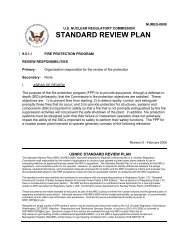
Figure 1: Fire PRA Process and Module Structure 8<br />
Figure 2: General Analysis Flow Chart for Task 11 – Detailed Fire Modeling 45<br />
List of Tables<br />
Table 1: Fire Ignition Frequency Bins Specific to LPSD Conditions 25<br />
Table 2: Fire Frequency Bins and Generic Frequencies 28<br />
Table 3: Quantitative Screening Criteria for Single PAU Analysis 34<br />
Table 4: Quantitative Screening Criteria for All Screened PAUs 35<br />
Table 5: Zone of Influence and Severity Factor Recommendations 40<br />
Table 6: Recommended Severity Factors and Suppression Curves for Ignition<br />
Sources in the Frequency Model 47<br />
Table A-1: Bins Considered for LPSD Data Analysis A-2<br />
Table A-2: Event Counts by Bin, Challenging Category and Operating Mode A-6<br />
Table A-3: Generic Fire Ignition Frequency Model for U.S. Nuclear<br />
Power Plants A-8<br />
Table A-4: Fire Type Split Fractions A-9<br />
Table A-5: Fire Event Classification A-10<br />
vi
Draft For Public Comment<br />
Executive Summary<br />
Methods for the application of Probabilistic Risk Assessment (PRA) to internal fire events<br />
during full-power operation of Nuclear Power Plants (NPPs) have evolved based on an extensive<br />
development process that began in the 1970s. Recently, existing fire PRA methods and<br />
evolutionary advances were consolidated through a collaborative effort between the U.S. Nuclear<br />
Regulatory Commission (<strong>NRC</strong>) Office of Nuclear Regulatory Research (RES) and the Electric<br />
Power Research Institute (EPRI). This work led to publication, in 2005, of the EPRI/<strong>NRC</strong>-RES<br />
Fire PRA Methodology for Nuclear Power Facilities [1]. Even these most recent fire PRA<br />
methods continue to evolve based on their application by industry and on the communication of<br />
lessons learned to both industry and the <strong>NRC</strong>.<br />
In contrast, fire PRAs for Low Power and Shutdown (LPSD) conditions have been conducted in<br />
only a few cases and all of the known analyses were based on methods and data that pre-date the<br />
RES/EPRI full-power fire PRA method. Methods for conducting such studies have not<br />
previously seen the same level of development as have the full-power methods and no<br />
comprehensive source for analysis guidance compatible with the current state-of-the art fire risk<br />
methods (e.g., [1]) is known to exist prior to this document. The LPSD fire PRA methodology<br />
presented here is presented as an extension of, or supplement to, the RES/EPRI full-power fire<br />
PRA method. That is, the LPSD method relies extensively on the extension of full-power<br />
analysis methods to LPSD conditions. As a result, documentation of the methodology as<br />
presented here focuses on those elements where the full-power methods should be adapted or<br />
extended to address LPSD conditions.<br />
LPSD plant operating states (POSs) potentially include a broad range of conditions for power,<br />
temperature and pressure levels. This methodology assumes that LPSD PRA might include plant<br />
operations at roughly the 30% power level and lower; hence, the LPSD conditions encompass a<br />
very broad spectrum of potential operating conditions.<br />
vii
Draft For Public Comment<br />
Acknowledgements<br />
The authors acknowledge the contributions of Dr. Mardy Kazarians of Kazarians and Associates<br />
to the development of this document. Mardy was a key contributor to the development of the<br />
initial drafts of this document. We also wish to thank Jeff Mitman of the <strong>NRC</strong> New Reactors<br />
Office for his support in developing this document. Jeff provided us with many background<br />
references relative to low power and shutdown risk analysis, the developing LPSD PRA<br />
standard, and plant operations. He supported us through the early development stages during a<br />
series of conversations on these subjects. We also acknowledge the contributions of Dr. Ron<br />
Boring of Idaho National Laboratory and thank him for his contributions to early drafts of the<br />
report in the area of human reliability analysis. Finally, we gratefully acknowledge the support<br />
and patience of our <strong>NRC</strong> technical monitor, Hugh ‘Roy’ Woods of the <strong>NRC</strong> Office of Nuclear<br />
Regulatory Research.<br />
ix
Draft For Public Comment<br />
ADAMS<br />
ANS<br />
ANSI<br />
ASME<br />
BWR<br />
CCDP<br />
CDF<br />
CFR<br />
CLERP<br />
dc<br />
EOP<br />
EPRI<br />
FAQ<br />
FEDB<br />
FEP<br />
HEAF<br />
HEP<br />
HFE<br />
HRA<br />
HRR<br />
ICDP<br />
ID<br />
ILERP<br />
IS<br />
LCO<br />
LERF<br />
LOCA<br />
LPSD<br />
MCB<br />
M<strong>CR</strong><br />
MG<br />
NFPA<br />
NPP<br />
<strong>NRC</strong><br />
PAU<br />
POS<br />
PRA<br />
PWR<br />
RCP<br />
RES<br />
RG<br />
RISC<br />
RPS<br />
SRV<br />
T/G<br />
ZOI<br />
Abbreviations and Acronyms<br />
Agency-wide Documents Access and Management System<br />
American Nuclear Society<br />
American National Standards Institute<br />
American Society of Mechanical Engineers<br />
Boiling Water Reactor<br />
Conditional Core Damage Probability<br />
Core Damage Frequency<br />
Code of Federal Regulations<br />
Conditional Large Early Release Probability<br />
Direct current<br />
Emergency Operating Procedure<br />
Electric Power Research Institute<br />
Frequently Asked Question<br />
Fire Events Database<br />
Fire Emergency Procedure<br />
High Energy Arcing Fault<br />
Human Error Probability<br />
Human Failure Event<br />
Human Reliability Analysis<br />
Heat Release Rate<br />
Incremental Core Damage Probability<br />
Identifier<br />
Incremental Large Early Release Probability<br />
Ignition Source<br />
Limiting Condition of Operation<br />
Large Early Release Frequency<br />
Loss of Coolant Accident<br />
Low Power and Shutdown<br />
Main Control Board<br />
Main Control Room<br />
Motor-Generator<br />
National Fire Protection Association<br />
Nuclear Power Plant<br />
Nuclear Regulatory Commission<br />
Physical Analysis Unit<br />
Plant Operating State<br />
Probabilistic Risk Assessment<br />
Pressurized Water Reactor<br />
Reactor Coolant Pump<br />
The Office of Nuclear Regulatory Research (at <strong>NRC</strong>)<br />
Regulatory Guide<br />
Risk Informed Standards Committee<br />
Reactor Protection System<br />
Safety Relief Valve<br />
Turbine/Generator<br />
Zone of Influence<br />
xi
Draft For Public Comment<br />
1.1 Introduction and Purpose<br />
1 Introduction<br />
Methods for the application of Probabilistic Risk Assessment (PRA) to internal fire events<br />
during full-power operation of Nuclear Power Plants (NPPs) have evolved based on an extensive<br />
development process that began in the 1970s. Recently, existing fire PRA methods and<br />
evolutionary advances were consolidated through a collaborative effort between the U.S. Nuclear<br />
Regulatory Commission (<strong>NRC</strong>) Office of Nuclear Regulatory Research (RES) and the Electric<br />
Power Research Institute (EPRI). This work led to publication, in 2005, of the EPRI/<strong>NRC</strong>-RES<br />
Fire PRA Methodology for Nuclear Power Facilities [1] (referred to in this document more<br />
simply as either “the RES/EPRI full-power fire PRA method” or “reference [1]”). Even these<br />
most recent fire PRA methods continue to evolve based on their application by industry and on<br />
the communication of lessons learned to both industry and the <strong>NRC</strong>. Many of the currently<br />
operating U.S. NPPs are actively engaged in the conduct of fire PRAs driven, in part, by licensee<br />
decisions to transition to the alternative risk-informed, performance-based fire protection rules as<br />
embodied in National Fire Protection Association (NFPA) Standard 805 [2] and the Code of<br />
Federal Regulations (CFR) Section 10CFR50.48(c) [3].<br />
In contrast, fire PRAs for Low Power and Shutdown (LPSD) conditions have been conducted in<br />
only a few cases and all of the known analyses were based on methods and data that pre-date the<br />
RES/EPRI full-power fire PRA method. Methods for conducting such studies have not<br />
previously seen the same level of development as have the full-power methods and no<br />
comprehensive source for analysis guidance compatible with the current state-of-the art fire risk<br />
methods (e.g., [1]) is known to exist prior to this document. The methodology presented here is<br />
presented as an extension of, or supplement to, the RES/EPRI full-power fire PRA method [1].<br />
That is, the LPSD method relies extensively on the extension of full-power analysis methods to<br />
LPSD conditions. As a result, documentation of the methodology as presented here focuses on<br />
those elements where the full-power methods should be adapted or extended to address LPSD<br />
conditions.<br />
1.2 Scope<br />
LPSD plant operating states (POSs) potentially include a broad range of conditions for power,<br />
temperature and pressure levels. For reference, the American National Standard Low Power and<br />
Shutdown PRA Methodology 1 [4] defines key terms relevant to LPSD PRAs as follows:<br />
1) “Low Power - Power levels at which major secondary components are out of service as a<br />
plant shuts down or starts up. This is typically a transition mode to/from hot/cold<br />
1 The cited quotes are based on the joint American National Standards Institute (ANSI) and American Nuclear<br />
Society (ANS) standard ANSI/ANS-58.22-200x, DRAFT #8C, for the Risk Informed Standards Committee (RISC)<br />
Reballot & Public Review, June 2008. At the time the current document was prepared, this was the most recent<br />
version of the LPSD PRA standard available. The reader should be aware that the standard is a document in<br />
transition and should review updated versions, as available, for wording changes.<br />
1
Draft For Public Comment<br />
shutdown. Designated as Startup in a boiling water reactor (BWR) when transitioning<br />
from cold shutdown to power operations.”<br />
2) “Low power: a POS (or set of POSs) during which the reactor is at reduced power, below<br />
full-power conditions. In this POS, the power level may be changed as the reactor is<br />
shutting down or starting up. The power level that distinguishes full power and low<br />
power is the power level below which major plant evolutions are required to reduce or<br />
increase power (e.g., taking manual control of feedwater level).”<br />
3) “LPSD evolution: a series of connected or related activities, such as a reduction in power<br />
to a low level, or plant shutdown, followed by the return to full-power plant conditions.<br />
LPSD evolutions are modeled as a series of POSs. Outage types are a general type of a<br />
shutdown evolution, and a refueling outage is a specific example. Reducing power to<br />
30% in order to conduct maintenance or an operational activity is another example of a<br />
low-power evolution. LPSD evolutions are characterized by a transition down to the POS<br />
where the activity is conducted, followed by a transition back to full power.”<br />
Note that even though these definitions all come from the same document, they are not entirely<br />
consistent. It is anticipated that the final revisions of the draft LPSD PRA standard will resolve<br />
the differences and settle on final definitions for these terms. Generally, the differences in<br />
phrasing are relatively minor and this methodology adopts these definitions with the intent of<br />
maintaining consistency with this quality standard. Consistent with these excerpts and for<br />
general purposes, this methodology assumes that LPSD PRA might include plant operations at<br />
roughly the 30% power level and lower.<br />
One implication of this assumption is that LPSD conditions encompass a very broad spectrum of<br />
potential operating conditions. At one end of the POS spectrum, the reactor may be producing<br />
power with the control rods partly out, pressure and temperature of the main cooling loop very<br />
close to full-power conditions, and decay heat cooling systems not yet functioning (due to<br />
system pressures). At the other end of the POS spectrum, LPSD includes refueling outage<br />
conditions where all the rods are inserted, the main reactor vessel is open and flooded with<br />
refueling pool borated water, and the reactor is at near-ambient temperature. During refueling,<br />
depending on the maintenance needs, only one decay heat removal loop may be available for a<br />
limited time and plant modification activities could be underway.<br />
1.3 Document Organization<br />
An overview of the LPSD fire PRA method is provided in Section 2 below. The overview<br />
defines the tasks of the methodology. The selection of POSs and the equations for estimating<br />
overall plant core damage frequency (CDF) and large early release frequency (LERF) are<br />
discussed in Section 3. Section 4 provides a detailed discussion of each technical element of the<br />
analysis methodology. Note that the subsections within Section 4 follow the same ordering as<br />
the chapters and technical tasks as defined in Volume 2 of the RES/EPRI full-power fire PRA<br />
methodology [1].<br />
2
Draft For Public Comment<br />
2 Overview of LPSD Fire PRA Methodology<br />
2.1 Structural Overview<br />
An internal fire event during LPSD operations can occur from either an equipment item<br />
malfunction (e.g., a short in a switchgear may lead to arcing inside the device, rapid release of<br />
energy, and ignition of switchgear internals) or a transient combustible or activity (e.g., welding<br />
done for repair or plant upgrade). These are the same two types of fire events considered in fullpower<br />
fire PRA. It is possible that the characteristics of an LPSD fire event (e.g., intensity or<br />
amount of fuel available) may be different from a similar class of events during full-power<br />
operation. However, the underlying fire behaviors of interest remain the same (e.g., ignition of<br />
combustible materials leading to plume formation, radiant heating, and other potentially<br />
damaging effects). Therefore, in principle, the methodology developed for full-power fire PRA<br />
[1] should be applicable to LPSD conditions. Clearly some of the parameters and conditions<br />
should be adjusted to reflect the special conditions of LPSD POSs.<br />
The methodology presented in this document is structured to coincide with the RES/EPRI fullpower<br />
fire PRA method. Therefore, the discussions provided in this document assume that the<br />
reader is familiar with that method and the related data as presented in reference [1]. The task<br />
elements of the RES/EPRI full-power fire PRA method are each discussed. These discussions<br />
focus on the differences introduced by virtue of the LPSD perspective. Note that for some task<br />
elements the differences are quite minor or even nonexistent.<br />
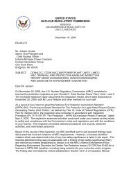
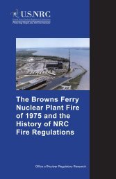
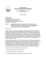
The RES/EPRI full-power fire PRA methodology defines 16 technical task elements and<br />
provides a detailed discussion, supporting data, and other information for each task. Figure 1<br />
(presented at the end of Section 2) is the flow chart used in the RES/EPRI full-power fire PRA<br />
method to illustrate the interrelationship among the different tasks of the methodology. The<br />
same set of tasks and flow chart apply to LPSD fire PRA. Each task is discussed separately<br />
below in Section 3.<br />
The RES/EPRI full-power fire PRA method for at-power conditions assumes that certain<br />
information will be available based on prior completion of a corresponding plant internal events<br />
PRA. If an internal events analysis is not available, then the fire PRA analyst is responsible for<br />
developing and validating the required information. Similarly, the LPSD fire PRA method<br />
assumes that certain information will be available based on prior completion of a LPSD internal<br />
events PRA. The information that is assumed to be available includes:<br />
Definition of LPSD POSs that will be addressed in terms of core power level, core<br />
cooling system pressure and temperature, equipment status (functional or under<br />
maintenance), special activities (e.g., maintenance and plant upgrade), status of barriers<br />
(e.g., doors propped open to allow certain activity, etc.);<br />
A list of initiating events for each POS as defined in the LPSD internal events PRA<br />
(e.g., loss of service water, loss of direct current (dc) power, etc.);<br />
A plant response model for each LPSD initiating event and for each relevant POS of<br />
interest;<br />
3
Draft For Public Comment<br />
A list of equipment and their failure modes of interest to the LPSD internal events<br />
PRA; and<br />
Human error scenarios integrated in the LPSD internal events plant response model.<br />
It is also assumed that an at-power fire PRA has been completed and is available. Information<br />
assumed to be available based on the at-power fire PRA includes:<br />
Plant partitioning results which divide the plant into fire compartments or,<br />
equivalently, into physical analysis units (PAUs); 2<br />
The listing of equipment included in the at-power fire PRA plant response model (i.e.,<br />
selected equipment per Task 2 of the RES/EPRI full-power fire PRA method);<br />
The listing of cables associated with selected equipment;<br />
Any additional initiating events that are specific to the fire analysis;<br />
Equipment and ignition source counting results;<br />
Control circuit failure modes and effects analysis reports; and<br />
Component and cable mapping/routing results for the circuits in the circuit analysis<br />
report.<br />
If any of this information is not available, the analyst should generate the needed information.<br />
2.2 Key Assumptions and Potential Limitations<br />
This methodology is based on a number of key assumptions, and these key assumptions which<br />
have implications for both the scope of the methodology and for potential limitations to<br />
application of the methodology. These key assumptions and the associated implications are<br />
summarized as follows.<br />
Assumption 1: The LPSD method assumes that a full-power fire PRA has been<br />
completed consistent with the general approach defined by the RES/EPRI full-power fire<br />
PRA methodology.<br />
Impact of this assumption on the methodology: The LPSD method takes as given that<br />
certain analysis tasks have already been completed and will, at most, require review and<br />
updating to address the LPSD conditions. For example, it is assumed that the task of<br />
identifying and counting fixed fire ignition sources within the plant has been completed.<br />
Hence, the LPSD analysis should only consider changes that might be associated with<br />
LPSD conditions (e.g., changes in the operational status of equipment, changes in the<br />
nature and likelihood of transient fuel sources that might be introduced during an outage,<br />
etc.).<br />
2 <strong>NUREG</strong>/<strong>CR</strong>-6850, EPRI 1011989 [1] uses the phrase “fire compartments” and the American Society of<br />
Mechanical Engineers (ASME) PRA quality standard [10] uses the phrase “physical analysis units.” The<br />
differences are largely semantic in nature and this method document has adopted the language of the PRA standard<br />
in this regard.<br />
4
Draft For Public Comment<br />
Implications: This assumption is thought to carry few practical implications. An<br />
early conclusion reached by the authors was that it is wholly impractical to perform an<br />
analysis of LPSD fire risk without first completing an assessment of the full-power fire<br />
risk. An analyst attempting to conduct an LPSD fire analysis without first completing a<br />
full-power fire analysis would, in effect, be forced to do nearly all of the work associated<br />
with a full-power fire risk study simply to establish the required input for beginning the<br />
LPSD risk study.<br />
Assumption 2: The LPSD fire PRA method assumes that an LPSD PRA has already<br />
been completed for internal event accident initiators.<br />
Impact of this assumption on the methodology: This parallels an equivalent<br />
assumption made in the RES/EPRI full-power fire PRA methodology; namely, that a fullpower<br />
internal events PRA has been completed prior to conducting the full-power fire<br />
PRA. In general, the impact on the LPSD fire PRA methodology is also the same;<br />
namely, the LPSD fire PRA method calls for the analyst to build a fire plant response<br />
model beginning from the corresponding model developed for the LPSD internal events<br />
PRA. The fire method thereby focuses on incorporating required changes and additions<br />
to address those aspects of plant response that are unique to fire (e.g., fire-induced<br />
spurious actuation of plant equipment, potential new initiators or sequences, and fire<br />
response procedures).<br />
Implications: The most significant implication of this assumption is that the LPSD<br />
fire PRA method assumes that the relevant POSs to be evaluated will have been defined<br />
in the LPSD internal events PRA. This method assumes that, at least nominally, the same<br />
set of POSs is then carried forward to the fire PRA. Based on this assumption, this<br />
document does not explicitly address the process or criteria by which the POSs will<br />
actually be defined. Defining LPSD POSs is an analytical challenge with far-reaching<br />
implications and is the focus of substantial debate in the more general PRA community.<br />
The resolution of this challenge lies beyond the scope of this document. It is also<br />
acknowledged that the fire analysis will present unique challenges with respect to POS<br />
definition. This method, for example, recommends that the LPSD fire PRA characterize<br />
and quantify the fire-specific plant configuration changes that occur with respect to each<br />
POS analyzed (e.g., breaching of fire barriers, staffing by plant personnel and contractors,<br />
introduction of new transient combustibles, increased hot work, fire protection system<br />
unavailability, maintenance activities, etc.). The implied work scope could become<br />
burdensome if a high level of detail for all possible POSs is sought. Methods for the<br />
management of the work scope challenge will likely develop through practical<br />
application, but cannot be defined a-priori. One general approach that might be<br />
especially helpful would be screening methods that would define the subset of POSs to be<br />
included in, or conversely excluded from, the quantitative fire analysis; but again, the<br />
more general state of POS definition guidance is not yet mature enough to support<br />
development of such screening approaches.<br />
Assumption 3: Development of detailed human reliability analysis (HRA)<br />
quantification methods for application to the LPSD fire PRA lie beyond the scope of this<br />
document.<br />
5
Draft For Public Comment<br />
Impact of this assumption on the methodology: This parallels an equivalent<br />
assumption made in the RES/EPRI full-power fire PRA methodology; namely, that postfire<br />
HRA methods will rely upon general practice for HRA in other contexts and that<br />
specific guidance for application to fire conditions will be developed by the HRA<br />
community. This document does not explicitly address HRA quantification methods.<br />
Implications: HRA is a unique area of methodology development whose implications<br />
extend well beyond the boundaries of a fire PRA. HRA quantification in the context of<br />
general LPSD plant operations is an active area of debate and development in the HRA<br />
technical community. A joint effort is already well underway between RES and EPRI to<br />
develop fire HRA quantification guidance for full-power fire PRA applications (see<br />
further discussion in Section 4.12). The LPSD fire PRA method assumes that the HRA<br />
community will ultimately develop LPSD analysis guidance and will extend that<br />
guidance to include the treatment of fire conditions. Section 4.12 discusses prior LPSD<br />
HRA analyses and applications, the updated EPRI-RES fire HRA guidance and<br />
considerations relevant to the application of that guidance to LPSD applications.<br />
However, the resolution of the LPSD HRA challenge lies beyond the scope of this<br />
document.<br />
Assumption 4: LPSD Fire frequencies are estimated based on past plant experience in<br />
the same manner that fire frequencies were estimated for the RES/EPRI full-power fire<br />
PRA methodology and using the same root database (i.e., the EPRI fire event database<br />
(FEDB)).<br />
Impact of this assumption on the methodology: The development of a new FEDB or<br />
the gathering of substantially new information for incorporation into the existing FEDB<br />
lie beyond the scope of this project. Hence, this method followed the approach used in<br />
the RES/EPRI full-power fire PRA methodology. If the RES/EPRI full-power fire PRA<br />
methodology concluded that the frequency of fires for a given fire source was not<br />
dependent on the POS, this method has made the same assumption (i.e., the fire<br />
frequency for many ignition source bins reflects fires occurring during all modes of plant<br />
operation). New fire frequencies are calculated only for those ignition source bins where<br />
the RES/EPRI full-power fire PRA methodology concluded that the shutdown fire<br />
frequency might vary substantially from the at-power fire frequency (e.g., transients and<br />
hot work fires).<br />
Implications: The existing FEDB has limitations that make it difficult to parse fire<br />
events to the extent that might be considered desirable. While this was also true for the<br />
RES/EPRI full-power fire PRA methodology, there are some unique implications in the<br />
context of LPSD conditions. In particular, while there are some exceptions, the fire event<br />
database does not generally identify the specific POS that a plant was in when a<br />
particular fire occurred. Rather, the vast majority of records only classify the POS as<br />
either at-power or shutdown (or they fail to specify a plant state at all). As a result, it is<br />
not currently possible to provide estimates of fire frequency that are POS-specific. An<br />
RES/EPRI collaborative effort is underway to expand and improve the EPRI FEDB. The<br />
planned improvements should afford some opportunity to improve the ability to parse fire<br />
events.<br />
6
Draft For Public Comment<br />
Assumption 5: Consistent with the LPSD PRA standard [4] 3 , the LPSD fire PRA end<br />
states considered here are limited to CDF and LERF.<br />
Impact of this assumption on the Methodology: While the methodology presented<br />
here could be extended to include other end states, it should be emphasized that this<br />
document makes no attempt to address any end states other than CDF and LERF.<br />
Implications: During certain LPSD POSs, depending on the specific conditions,<br />
radionuclide release may occur from events other than core damage (the focus of fullpower<br />
PRA). For example, during a refueling outage coolant boiling in the core,<br />
uncovering the core, or fuel bundle mishandling could be considered as possible endstates<br />
for a risk analysis. Consistent with the standard [4], these alternative end states lie<br />
outside the scope of this methodology. Also consistent with the standard [4], this<br />
document excludes consideration of potential release scenarios associated with either the<br />
spent fuel pool or on-site dry cask storage of spent fuel.<br />
3 At the time the current document was prepared, reference [4] was the most recent version of the LPSD PRA<br />
standard available. The reader should be aware that the standard is a document in transition and should review<br />
updated versions, as available, for wording or scope changes.<br />
7
Draft For Public Comment<br />
TASK 1: Plant Boundary &<br />
Partitioning<br />
TASK 3: Fire PRA Cable<br />
Selection<br />
SUPPORT TASK A: Plant<br />
Walk Downs<br />
TASK 4: Qualitative<br />
Screening<br />
TASK 6: Fire Ignition<br />
Frequencies<br />
SUPPORT TASK B: Fire<br />
PRA Database<br />
TASK 7A: Quantitative<br />
Screening -I<br />
TASK 8: Scoping Fire<br />
Modeling<br />
TASK 7B: Quantitative<br />
Screening -II<br />
B<br />
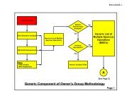
Figure 1: Fire PRA Process and Module Structure (part 1 of 2).<br />
TASK 2: Fire PRA<br />
Component Selection<br />
TASK 5: Fire-Induced Risk<br />
Model<br />
TASK 12A: Post-Fire HRA:<br />
Screening<br />
8
Draft For Public Comment<br />
B<br />
Detailed Fire Scenario Analysis<br />
TASK 9: Detailed Circuit<br />
Failure Analysis<br />
TASK 10: Circuit Failure<br />
Mode & Likelihood Analysis<br />
TASK 13: Seismic-Fire<br />
Interactions<br />
TASK 14: Fire Risk<br />
Quantification<br />
TASK 15: Uncertainty &<br />
Sensitivity Analyses<br />
TASK 16: Fire PRA<br />
Documentation<br />
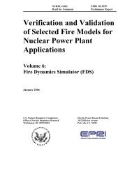
Figure 1: Fire PRA Process and Module Structure (part 2 of 2).<br />
TASK 11: Detailed Fire<br />
Modeling<br />
A. Single Compartment<br />
B. Multi-Compartment<br />
C. Main Control Room<br />
TASK 12B: Post fire HRA:<br />
Detailed & recovery<br />
9
Draft For Public Comment<br />
3 LPSD PRA CDF and LERF<br />
A key challenge of LPSD PRA, both for internal events and fire, is the definition of the POSs to<br />
be analyzed. There are many possible solutions to this challenge. This document takes no<br />
position as to the ‘correct’ solution. Whatever approach is ultimately taken, this method assumes<br />
that a POS set will be defined as a part of the plant’s internal events LPSD PRA and that the<br />
defined POS set will be equally valid and inclusive so as to serve the needs of the LPSD fire<br />
PRA. It is therefore assumed that the analyst will have a set of POSs defined prior to attempting<br />
LPSD fire PRA effort. Two general approaches to defining the POSs are anticipated. The POS<br />
set could be “complete” so as to cover all possible POSs in substantive detail. The set could also<br />
be a limited, well defined grouping of POSs intended to represent a typical outage or for use in a<br />
focused-scope analysis. This method is neutral to this aspect of the analysis. The approach<br />
taken to defining POSs for analysis will clearly impact the scope of the analysis, but will not<br />
alter the fundamental nature of the fire PRA methodology. Instead, the choice of approach will<br />
be driven by the objectives and intended applications of the analysis.<br />
An evaluation based on a more complete set of POSs will facilitate modeling of actual plant<br />
configurations and equipment status changes that could increase, or reduce, fire risk. For each<br />
POS that exists there may be special plant configurations that are unique to a specific outage<br />
(e.g., steam generator replacement, flooding of the spent fuel pool). These special plant<br />
configurations will require particular consideration since initiators and mitigating equipment may<br />
vary from the original POS. PRA models for each POS should also reflect each special<br />
configuration.<br />
If the objective of the analysis is to estimate the total risk over the course of an outage sequence<br />
(e.g., from the beginning of plant shutdown from power to the point of restart), the CDF and<br />
LERF calculations should be repeated for each POS and combined according to the following<br />
equation:<br />
Where:<br />
CDFΣPOS = Σ i CDFPOS(i) x ft POS(i)<br />
CDFΣPOS :<br />
The total CDF of all POSs combined in number of events per reactor year<br />
CDFPOS(i): The instantaneous CDF of specific POS(i)<br />
ft POS(i) :<br />
The fraction of time that each POS exists<br />
If a specific one-time POS under a specific set of conditions is analyzed, the CDF and LERF<br />
should be estimated using the same equation, except that only one POS is considered. Therefore,<br />
we can write:<br />
CDF POS(i) = CDFPOS(i) x ft POS(i)<br />
10
Draft For Public Comment<br />
Where:<br />
CDF POS(i) :<br />
CDFPOS(i):<br />
ft POS(i) :<br />
The CDF of POS(i) in number of events per reactor year<br />
The instantaneous CDF of specific POS(i)<br />
The fraction of time that POS i exists<br />
The same set of equations applies to LERF calculations where CDF is simply replaced with<br />
LERF.<br />
11
Draft For Public Comment<br />
4 Detailed Methodology<br />
4.1 Task 1: Plant Boundary Definition and Partitioning<br />
The purpose and scope for this task remains the same as presented in reference [1]. This section<br />
provides supplemental guidance for conducting the plant boundary definition and partitioning<br />
tasks in support of the LPSD fire PRA. As in the full-power fire PRA, the plant is divided into a<br />
number of PAUs. The analysis then considers the impact of fires in a given PAU, and fires that<br />
might impact multiple PAUs. This practice supports both the organization of the PRA<br />
information and analysis, and provides a framework for reporting risk results.<br />
Task 1 establishes the process for defining the overall plant boundary and partitioning of the<br />
plant into PAUs. The product of this task will be a list of PAUs that encompasses the nuclear<br />
power plant under analysis.<br />
Analysts have two choices: (1) use the same set of PAUs as per the definitions established in the<br />
full-power fire PRA or (2) redefine the PAUs based on the barrier configurations and conditions<br />
specific to the POS. Both approaches have merits but this report advocates for maintaining the<br />
PAU definitions as per the full-power fire PRA with few exceptions. This approach ensures that<br />
plant locations are identified consistently among the analyses and will allow the results for the<br />
same plant location under different operating conditions to be quickly and easily identified. If<br />
the PAU boundaries are redefined, then tracking results becomes far more difficult and<br />
burdensome. The two significant exceptions to this recommendation are as follows:<br />
(1) The analysis should verify that the full-power fire PRA plant boundary encompasses all<br />
plant areas of potential interest to the LPSD fire PRA. If it does not, then the global<br />
analysis boundary is expanded and new PAUs are defined.<br />
(2) The analysis should consider the treatment afforded the containment structure in the<br />
full-power fire PRA and determine if an alternative treatment is appropriate.<br />
Containment fires are relatively rare while the plant is at full-power operation. For<br />
those BWRs with inerted containment, fires during full-power operation are not<br />
analyzed (no fire frequency is assigned to these containments per the guidance in<br />
reference [1]). During LPSD operations, these conditions can change and the changes<br />
could impact containment partitioning decisions.<br />
The primary challenge to the LPSD fire PRA with respect to Task 1 is that the partitioning<br />
elements that defined the compartments in the full-power fire PRA (e.g., walls, ceilings/floors,<br />
spatial separation, etc) are subject to modification during LPSD plant operations. For example,<br />
equipment hatches in ceilings/floors may be removed, normally closed doors may be propped<br />
opened, fire barrier penetrations may be breached (e.g., to support equipment or cable work), the<br />
containment structure may be open, and for BWRs, containment will no longer be inerted. The<br />
LPSD fire PRA will need to define and address such changes, but this need not force changes to<br />
previous (i.e., at power) partitioning decisions. Rather, changes in the status or integrity of a<br />
credited partitioning feature or element can be addressed during Task 11, and in particular Task<br />
11c - the multi-compartment fire analysis (see Section 3.11 for additional discussion).<br />
If the decision is made to alter the partitioning of any plant locations, the analysis should (1)<br />
define the partitioning changes and (2) provide a concise mapping between PAUs as defined in<br />
12
Draft For Public Comment<br />
the full-power fire PRA and in the LPSD fire PRA. As in the full-power fire PRA, the LPSD<br />
PAUs should collectively encompass all locations within the global analysis boundary with no<br />
exclusions and no overlap between compartments (the set of PAUs is both complete and<br />
exclusive).<br />
In Section 1.3.1 of reference [1]; the guidance cautions the analyst to avoid “excessive<br />
partitioning” and an over-reliance on multi-compartment fire scenarios as significant contributors<br />
to plant fire risk. If the recommendations discussed above are followed (i.e., the same PAU<br />
definitions are retained from the full-power analysis), then it is likely that there will be more<br />
contributing multi-compartment scenarios for LPSD than the full-power fire PRA. This is<br />
because normally closed fire barriers and other partitioning features may be opened during LPSD<br />
operations. This is inevitable, and is not considered to detract from the quality or validity of the<br />
LPSD fire PRA provided appropriate treatment is afforded to the relevant multi-compartment<br />
fire scenarios (i.e., in Task 11c).<br />
The same procedure as that described in reference [1] for full-power fire PRA applies here as<br />
well with the following clarifications.<br />
Step 1: Selection of Global Plant Analysis Boundary:<br />
This task begins with an assessment of the global plant analysis boundary definition<br />
established in the full-power fire PRA. The guidance provided in reference [1] seeks a<br />
liberal definition of the global plant analysis boundary. Hence, for most analyses it is<br />
considered unlikely that the boundary will need to be expanded to suit the LPSD fire PRA;<br />
however, the LPSD analysis should determine whether the global plant analysis boundary<br />
should be expanded to encompass new areas of the plant. The definition of the global plant<br />
analysis boundary may need to be expanded if any locations excluded from the full-power<br />
analysis are identified as potentially relevant to the LPSD analysis. For example, the unit<br />
under analysis may establish electrical ties via temporary cabling to a sister unit during<br />
shutdown that would not be present while at power (e.g., to make up for de-energized<br />
power supply busses undergoing maintenance during the shutdown). If these ties meet the<br />
criteria for equipment/cable selection and the corresponding areas of the sister unit were<br />
outside the global analysis boundary for the unit’s at-power fire PRA, then the LPSD fire<br />
PRA global analysis boundary should expand accordingly.<br />
As with the full-power fire PRA, the LPSD fire PRA global plant analysis boundary should<br />
encompass all areas of the plant associated with both normal and emergency reactor<br />
operating and support systems, and power production (e.g., the turbine building). The<br />
unique aspect of this assessment for the LPSD analysis is that the terms “normal and<br />
emergency reactor operating and support systems” should encompass all defined POSs to<br />
be considered in the analysis rather than just full-power conditions. This holds the<br />
potential to introduce plant locations that were deemed outside the scope of the full-power<br />
fire PRA.<br />
Selection of the LPSD fire PRA global plant analysis boundary should begin with the fullpower<br />
fire PRA global plant analysis boundary. A review should be performed to ensure<br />
that locations not included within the full-power boundary could not contribute to fire risk<br />
under any of the defined LPSD POSs. In particular, the LPSD fire PRA plant analysis<br />
boundary should encompass all locations, including qualifying locations associated with a<br />
13
Draft For Public Comment<br />
sister unit at a multi-unit site, that house any of the LPSD fire PRA components and cables<br />
identified in Tasks 2 and 3 (see next two sections).<br />
Step 2: Plant Partitioning:<br />
The discussions provided in Section 1.5.2 of reference [1] apply in full to the LPSD fire<br />
PRA. As a general practice, this method recommends that the PAUs (i.e., the plant<br />
partitioning results) as developed for the full-power fire PRA be applied without<br />
modification to the LPSD fire PRA with two specific exceptions:<br />
(1) For any new locations added to the global analysis boundary in Step 1, partition those<br />
locations into PAUs consistent with the guidance in Section 1.5.2 of reference [1].<br />
(2) It is recommended that a review of the containment structure be performed to assess<br />
whether or not additional partitioning is appropriate.<br />
With respect to item (2) above, in a typical full-power fire PRA the containment structure<br />
is either not analyzed in detail (i.e., in the case of those plants whose containments are<br />
inerted during plant operations) or analyzed in limited detail (e.g., due to the relatively low<br />
frequency of fires inside containment during power operations that can affect core cooling).<br />
These conditions (inerting and low fire frequency) may not apply to LPSD operations and<br />
the analyst should anticipate that a more thorough examination of containment fires will be<br />
required. Hence, the purpose of item (2) above is to ensure that due consideration is given<br />
to the potential analytical needs of the containment fire analysis during the plant<br />
partitioning task. As always, partitioning decisions are ultimately up to the analyst but<br />
additional partitioning of the containment structure should be considered.<br />
Step 3: Compartment Information Gathering and Characterization:<br />
The discussions provided in Section 1.5.3 of reference [1] apply in full to the LPSD fire<br />
PRA.<br />
Step 4: Documentation:<br />
The discussions provided in Section 1.5.4 of reference [1] apply in full to the LPSD fire<br />
PRA. In addition, the analyst should take particular care to document any changes in plant<br />
partitioning made to support the LPSD fire PRA as compared to the full-power fire PRA.<br />
If any partitioning changes are made, task documentation should define those changes and<br />
provide a mapping of LPSD PAUs to full-power fire compartments.<br />
4.2 Task 2: Fire PRA Component Selection<br />
4.2.1 Background<br />
The objective of Task 2 is to create the LPSD fire PRA component list 4 . This list identifies the<br />
plant components that will be modeled in the LPSD fire PRA. The component list also identifies<br />
4 As in the full-power procedure, the terms “equipment” and “component” as used here are considered synonymous<br />
and are meant to include plant components such as valves, fans, pumps, etc.; structures; barriers; indicators; alarms;<br />
and other devices as appropriate. The terms generally exclude electrical cables as these are dealt with explicitly (see<br />
Task 3).<br />
14
Draft For Public Comment<br />
plant equipment for which the corresponding cables (power, control and instrumentation – see<br />
Task 3) need to be identified and located.<br />
This task builds upon foundations of equipment selection established by the full-power fire PRA.<br />
It also builds upon foundations established in a corresponding internal event LPSD PRA. Hence,<br />
as noted in Section 2, these two analyses are considered critical inputs to this task. If either<br />
analysis is not available, the analyst faces a substantial additional burden to generate the<br />
information that would normally be imported from these analyses and that effort lies outside the<br />
scope of this document.<br />
Given the wide range of possible POS conditions, essentially all of the components selected for<br />
inclusion in the full-power fire PRA will also be relevant to the LPSD fire PRA and should be<br />
retained in the LPSD fire PRA component list. However, component selection will need to be<br />
augmented with additional components unique to the conditions posed by the specific POSs<br />
associated with shutdown and with equipment outages during LPSD conditions (e.g., loss of the<br />
redundant train of a system to a fire while the other train is out of service for maintenance).<br />
The process for generating the LPSD fire PRA component list is fundamentally the same as the<br />
full-power analysis. The analyst, however, should consider each POS separately to ensure that<br />
potential accident initiators and mitigating equipment relevant to each POS are properly<br />
accounted for.<br />
Overall and for each POS, the component list needs to span:<br />
(1) equipment that, if affected by a fire, will cause an initiating event such that the<br />
appropriate fire-induced initiators can be defined;<br />
(2) all equipment necessary to support those mitigating functions and operator actions that<br />
are credited in the analysis in response to any initiator; and<br />
(3) equipment that can be a source of undesirable responses adverse to safety during a fireinduced<br />
accident sequence, (e.g., fire-induced spurious operations).<br />
The considerations cited for the selection of equipment in Section 2.2 of reference [1] are fully<br />
applicable to the LPSD fire PRA. In addition, it is recommended that the LPSD fire component<br />
list include the following:<br />
(1) all components included in the full-power fire PRA, and<br />
(2) all components credited in the Internal Events LPSD PRA, and in particular, equipment<br />
associated with electrically diverse systems.<br />
The input to Task 2 is much the same as those identified in Section 2.4.1 of reference [1] with<br />
the following additions:<br />
(1) Task 2 includes the mapping of identified components to plant locations (e.g., fire areas<br />
and/or PAUs). It is strongly recommended that the LPSD fire PRA use the same plant<br />
boundary and compartment definitions and location identification nomenclature as<br />
established in the corresponding full-power fire PRA. If the global analysis boundary is<br />
expanded to accommodate the needs of the LPSD fire PRA, then the additions should be<br />
clearly documented (e.g., identify locations that were deemed outside the scope of the<br />
full-power fire PRA but are included in the LPSD fire PRA). This approach will greatly<br />
simplify the process of component tracing and location documentation.<br />
15
Draft For Public Comment<br />
(2) The internal events LPSD PRA model for the specific POSs under consideration and the<br />
corresponding equipment lists are a required input.<br />
(3) Plant procedures applicable to the POSs being considered (e.g., emergency operating<br />
procedures, fire procedures, annunciator response procedures) are required in addition to<br />
at-power operating procedures.<br />
(4) The analysis will need to review plant Technical Specifications to determine possible<br />
limiting conditions of operation (LCOs) applicable to each defined POS conditions (see<br />
Task 2 Step 3).<br />
4.2.2 Procedure<br />
The steps that follow provide a method to create the LPSD fire PRA component list. The step<br />
structure is identical to that provided in Section 2.5 of reference [1]. As with the full-power fire<br />
PRA, as a practical matter, the LPSD fire PRA component selection task is an iterative process.<br />
Hence, as other tasks are performed, there may be reason to revisit and redo portions of Task 2<br />
during the development, screening, and eventual quantification of the LPSD fire PRA.<br />
Step 1: Identify Internal Events LPSD PRA Sequences to be included (and those to be<br />
excluded) in the LPSD fire PRA Model.<br />
This step for the fire LPSD task is identical to the corresponding step as described in<br />
Section 2.5.1 of reference [1] with one modification. For the purposes of the LPSD fire<br />
PRA, Step 1 reviews accident sequences from the full-power fire PRA and the internal<br />
events LPSD PRA (rather than only the internal events full-power PRA.)<br />
Possible Elimination of Sequences and Equipment - The identification of sequences that<br />
could generally be eliminated from the LPSD fire PRA is similar to the corresponding<br />
analysis element in reference [1] with the following additions:<br />
(1) In determining which sequences and equipment to include, or potentially exclude, from<br />
the LPSD fire PRA, consider all sequences included in the full-power fire PRA and<br />
those included in the internal events LPSD PRA.<br />
(2) It is recommended that all components included in the full-power fire PRA be retained<br />
for (i.e., not eliminated from) the LPSD fire PRA with few exceptions. In essence, the<br />
full-power fire PRA will already have established component locations and will have<br />
identified and traced related cables. Hence, there is likely little benefit to be gained by<br />
excluding such components from the fire LPSD analysis especially given that the LPSD<br />
fire PRA will include low-power (e.g., startup) POSs that will be quite similar in nature<br />
to the full-power plant configuration. If any components that were included in the fullpower<br />
fire PRA are excluded from the LPSD fire PRA, the exclusion should be noted<br />
and explained, including a discussion of the potential impact of these exclusions on the<br />
risk results.<br />
(3) As in the full-power fire PRA, justification for the exclusion of any sequences or<br />
equipment and the resulting impact on the “reduced” PRA model should be noted. In<br />
particular, the analyst should take care not to eliminate sequences or equipment that<br />
could adversely affect equipment credited in the LPSD fire PRA. For example,<br />
elements of an electric power distribution system may be considered for elimination<br />
(e.g., dc power distribution system elements). However, the analyst should be careful<br />
16
Draft For Public Comment<br />
not to eliminate those parts of the system that may be needed for proper functioning of<br />
credited equipment items (e.g., instrumentation loops).<br />
Possible Additions of Sequences and Equipment - Considerations relative to the addition of<br />
sequences and equipment are essentially the same as for the corresponding analysis<br />
element in the full-power fire PRA with the following clarifications:<br />
(1) As was the case for the full-power fire PRA as compared to the full-power internal<br />
events PRA, some sequences that were screened out of the internal events LPSD PRA<br />
based on low frequency of occurrence may need to be retained in the LPSD fire PRA.<br />
The bases for such additions would be similar to those leading to additions to the fullpower<br />
fire PRA. Specifically, a search should be conducted, in concert with carrying<br />
out all the steps of this procedure, for new functional challenges in the plant not<br />
otherwise accounted for especially because of fire-induced spurious actuation<br />
considerations.<br />
For example, spurious actuation of a high pressure pump while the reactor<br />
vessel is closed but in cold shutdown may lead to pressurizer safety relief valve<br />
(SRV) lift. Spurious actuation of the pump may have been deemed of sufficiently<br />
low probability in the internal events LPSD PRA that the sequence may have<br />
been screened out. However, fire-induced spurious actuation of the same pump<br />
(e.g., due to control cable failures) might be likely enough to warrant retention of<br />
the sequence.<br />
A review should be conducted for such scenarios originally eliminated from the internal<br />
events LPSD PRA to determine if new components should be added to the LPSD fire<br />
PRA component list implying that those components, their failure modes, and the<br />
associated sequences would be included in the LPSD fire PRA plant risk model (see<br />
Task 5). Particularly when considering the possible effects of spurious operations, new<br />
accident sequences and associated components of interest beyond those considered in<br />
the Internal Events LPSD PRA may be identified that should be addressed in the LPSD<br />
fire PRA. Each POS should be considered individually to determine applicability.<br />
Typically, new sequences might arise as a result of spurious events that:<br />
cause a loss of coolant accident (LOCA), e.g., drain down events;<br />
adversely affect plant pressure control, e.g., letdown or safety relief valve<br />
events;<br />
cause loss of cooling to core; or<br />
introduce other “new” scenarios that may not be addressed in the internal<br />
events LPSD PRA.<br />
(2) As with the full-power fire PRA, a review of the fire emergency procedures (FEPs) or<br />
similar fire-related instructions as such instructions apply to various LPSD POSs should<br />
be conducted (see also Task 12). In particular, fire-specific manual actions designed to<br />
preclude or overcome spurious operations will likely not have been addressed in the<br />
Internal Events LPSD PRA. For example:<br />
An FEP may require shutdown of a pump from the switchgear to avoid<br />
spurious actuation of the pump and pump damage due to cavitation. This may<br />
17
Draft For Public Comment<br />
cause demands on the pressurizer SRV and lead to sequences not modeled in the<br />
Internal Events LPSD PRA.<br />
Fire specific manual actions may cause an unintentional failure of a safety<br />
function or a subset of that functional response. For example, a proceduralized<br />
action may be to trip a power supply thereby disabling (“failing”) certain<br />
equipment in the plant.<br />
As with full-power considerations, the likely timing of the operator action as<br />
compared to when the affected component is needed should also be considered.<br />
Step 2: Review the Internal Events LPSD PRA Model Against the Fire Safe Shutdown<br />
Analysis:<br />
The impact of Step 2 on the LPSD fire PRA is likely to be more limited than the impact of<br />
this step on the full-power fire PRA. However, this step does retain some relevance to the<br />
LPSD fire PRA and should not be neglected.<br />
The fire safe shutdown analysis addresses regulatory requirements to demonstrate that, in<br />
the event of a plant fire, the plant will retain the ability to achieve hot-shutdown (or hotstandby)<br />
and ultimately to achieve and maintain cold shutdown. Hence, the safe shutdown<br />
procedures will overlap some of the POSs that will likely be defined in the LPSD fire PRA.<br />
To the extent that this overlap exists, Step 2 should be completed.<br />
The underlying steps (i.e., steps 2.1 through 2.5) are executed largely consistent with the<br />
treatment afforded in the full-power fire PRA. The most significant difference is that the<br />
review compares the fire safe shutdown analysis to the plant risk model developed for the<br />
internal events LPSD PRA rather than the treatment provided in the internal events fullpower<br />
PRA. The reconciliation effort in steps 2.1 through 2.4 compares the fire safe<br />
shutdown analysis to the internal events LPSD PRA rather than to the internal events fullpower<br />
PRA. When reconciling system or equipment differences due to end-state<br />
and mission considerations, the fire safe shutdown analysis will likely not deal at all with<br />
various POSs associated with the LPSD fire PRA. In particular, the fire safe shutdown<br />
analysis will typically not address any aspects of plant operations during refueling stages of<br />
a plant shutdown. When considering specific review of manual actions, the reconciliation<br />
effort should compare the fire safe shutdown analysis to the internal events LPSD PRA<br />
rather than to the internal events full-power PRA. Also, with respect to manual actions to<br />
be credited in the LPSD fire PRA, considerations should include both the need to achieve<br />
and maintain safe shutdown (e.g., given an automatic or manual trip from a low-power<br />
POS) and the need to maintain safe and stable conditions during other non-power POSs<br />
(e.g., refueling evolutions).<br />
Step 3: Identify Fire-Induced Initiating Events Based on Equipment Affected:<br />
The role of this step in the analysis is essentially identical for the LPSD fire PRA as for the<br />
full-power fire PRA. That is, to the extent the above steps have not already done so, this<br />
step addresses that equipment which, if affected by a fire, could cause an initiating event<br />
(e.g., forced shutdown of the plant from a low power state or a drain down event for other<br />
shutdown evolutions). As in the full-power analysis, the goal of Step 3 is to identify what<br />
initiator(s) will likely occur if a fire in any given compartment affects equipment identified<br />
on the LPSD fire PRA component list. For guidance, see Section 2.5.3 of reference [1]<br />
18
Draft For Public Comment<br />
with the following clarification: In addition to the considerations applicable to the fullpower<br />
fire PRA, for the LPSD fire PRA, consideration also extends to equipment whose<br />
failure would compromise the ability to maintain a safe and stable condition for each POS<br />
being considered. It is anticipated that new initiating events may need to be identified<br />
stemming from the specific conditions imposed by the POS. It must be noted here again<br />
that this guidance is focused on CDF and LERF. Other radionuclide release possibilities<br />
are not considered as part of the scope of this document.<br />
Step 4: Identify Equipment with Potential Spurious Actuations that may Challenge the<br />
Ability to Safely Maintain the Plant During Each POS:<br />
The role of this step in the analysis is essentially identical for the LPSD fire PRA as for the<br />
full-power fire PRA. This step is aimed at further expanding the LPSD fire PRA<br />
component list, and thus potentially the LPSD fire PRA plant risk model (Task 5), to<br />
include adequate consideration of the potential for harmful fire-induced spurious<br />
actuations. For guidance, see Section 2.5.4 of reference [1] with the following<br />
clarifications:<br />
(1) In addition to the considerations applicable in the full-power fire PRA, for the LPSD<br />
fire PRA it also extends to equipment whose spurious actuation would compromise the<br />
ability to maintain a safe and stable condition for each POS being considered.<br />
(2) The systematic review of potential spurious actuation concerns is conducted on the basis<br />
of accident sequence types and related mitigation system functions included in the<br />
internal events LPSD PRA plant risk model rather than the internal events full-power<br />
PRA plant risk model.<br />
(3) Table 2-2 of reference [1] presents (illustrative only) examples of how single and<br />
multiple spurious actuation failures might be important for some accident sequences. In<br />
addition to those examples provided for full-power conditions, the LPSD PRA should<br />
include consideration of spurious actuations impacting secondary-side cooling functions<br />
because these either may not have been considered, or may have been considered and<br />
screened out, during the full-power fire PRA.<br />
Step 5: Identify Additional Mitigating, Instrumentation, and Diagnostic Equipment<br />
Important to Human Response:<br />
The goal of this step in the LPSD fire PRA is identical to that of the corresponding step in<br />
the full-power fire PRA [1]. Namely, the goal is to expand the LPSD fire PRA component<br />
list, and thus potentially the LPSD fire PRA plant risk model (Task 5) to include other<br />
mitigating equipment, instrumentation, and diagnostic equipment necessary for human<br />
actions if not already addressed in previous steps for each POS. The structure and role of<br />
the underlying steps (5.1 and 5.2) remains unchanged.<br />
Step 5.1: Identify Human Actions of Interest: See Section 2.5.5.1 of reference [1] for<br />
guidance with the following clarifications:<br />
(1) The identification of human actions gives consideration to those human actions<br />
credited in the internal events LPSD PRA rather than those actions credited in the<br />
internal events full-power PRA.<br />
19
Draft For Public Comment<br />
(2) The review of human actions should consider all relevant plant procedures for all<br />
POSs being considered. This should include both general plant operations and any<br />
fire-specific procedures as available.<br />
Step 5.2: Identify Instrumentation and Diagnostic Equipment Associated with both<br />
Credited and Potentially Harmful Human Actions: See Section 2.5.5.2 of reference [1]<br />
for guidance. The following is an alternative example to those offered in reference [1]<br />
that should be included during the performance of Step 5.2:<br />
(1) The LPSD fire PRA will need to consider the potential role of the plant’s alternate<br />
shutdown panel in LPSD operations. If, for example, a main control room (M<strong>CR</strong>)<br />
fire were to occur during a shutdown evolution, the analysis will need to assess what<br />
benefit could be gained through use of the alternate shutdown panel(s) to control<br />
some of the plant systems.<br />
Step 6: Include “Potentially High Consequence” Related Equipment:<br />
As the final analysis step in performing Task 2, consideration is given to equipment<br />
associated with potentially high consequence events. The goal is to ensure that such events<br />
are not be prematurely screened, but are analyzed in more detail to determine their risk<br />
significance.<br />
High consequence events for full-power conditions are potentially relevant to low-power<br />
operations as well. These are defined per Section 2.5.6 of reference [1] (list items (a) and<br />
(b) in that section). To the extent that such events are relevant to low-power operations<br />
they should be considered consistent with the full-power fire PRA guidance. In addition to<br />
(a) and (b) in reference [1], for the purposes of the LPSD fire PRA, consideration of<br />
potentially high consequence events should be extended to include events where:<br />
(c) one or more related component failures, including spurious operations, where at least<br />
one failure/spurious operation is induced by a fire that by themselves results in fuel<br />
bundle damage either (1) when the reactor vessel and secondary containment structure<br />
are open (i.e., no primary or secondary containment) or (2) in a location outside<br />
containment to the extent that plant operations associated with the removal of fuel<br />
bundles from containment are included in the defined POS(s).<br />
<br />
Step 7: Assemble LPSD fire PRA component list:<br />
As in the full-power fire PRA, the final step is to assemble the LPSD fire PRA component<br />
list. This list is generally maintained in a supporting database. The most important<br />
elements of the database will be the component identifiers and the location of the<br />
component. This effectively defines the PRA damage targets within each PAU in terms of<br />
components. Section 2.5.7 of reference [1] provides recommendations relative to the type<br />
of information that should be recorded for each item on the component list. Similar<br />
information will be needed to support the LPSD fire PRA, but this information will also<br />
need to extend to all POSs being considered. Some component characteristics (e.g.,<br />
equipment identifier (ID), description, locations, system designation, and type) will remain<br />
the same regardless of the plant operating state. However, others (e.g., the normal<br />
position/status, desired position/status, failed electrical position, and failed air position) will<br />
change depending on the POS. It is recommended that the database structure be expanded<br />
20
Draft For Public Comment<br />
to capture, as relevant, variable aspects of each component identified and the relevant<br />
entries as applicable to each identified POS. Additionally, there could be temporarilystaged<br />
equipment (e.g., auxiliary diesel), which may be a part of the safe plant operation<br />
during a POS. These new equipment items would need to be added to the list.<br />
4.3 Task 3: Fire PRA Cable Selection<br />
The approach and process for identifying cables of potential interest to the LPSD fire PRA is<br />
essentially identical to that applied to the full-power fire PRA as documented in Section 3 of<br />
reference [1]. However, the following clarifications should be noted:<br />
Any and all cables selected for inclusion in the full power fire PRA will likely be<br />
included in the LPSD fire PRA. Any exceptions to this general practice should be<br />
identified and justified.<br />
The cable identification process considers the equipment and components identified in<br />
Task 2 of the LPSD fire PRA rather than the set of equipment identified in the<br />
corresponding full-power fire PRA. The LPSD fire PRA equipment list may contain new<br />
components not included in the full-power fire PRA and the cable selection process should<br />
be repeated for these new components. If, as part of maintenance activities during a POS,<br />
for equipment on the component list, temporary cables are installed or existing cables are<br />
re-routed, those cables should be added to the list.<br />
The full-power cable selection results should also be reviewed to ensure that<br />
component failure modes that may not have been of interest to the full-power fire PRA but<br />
that have unique implications to the LPSD POSs are identified and addressed. This might,<br />
for example, include the re-introduction of cables leading to spurious equipment actuations<br />
that were considered benign in the full-power analysis but which might not be benign in the<br />
context of one or more LPSD POSs. For example, the spurious operation of valves<br />
associated only with shutdown cooling systems might have little or no impact on at-power<br />
operations, but might compromise core cooling during one or more LPSD POS. Hence, it<br />
is possible that components, and their associated cables, that were properly screened out<br />
from the at-power fire PRA would need to be added to the LPSD fire PRA equipment and<br />
cable lists.<br />
Cable selection considers the potential impact of cable failures in the context of each<br />
POS being considered in the LPSD fire PRA.<br />
The final outcome of this task is a set of entries in the fire PRA Database identifying the cables<br />
of interest in terms of associated component serviced by the cable, cable function, and cable<br />
locations (see Section 3.5.6.1 of reference [1] for further detail). This information establishes the<br />
PRA damage targets in each PAU in terms of cables.<br />
4.4 Task 4: Qualitative Screening<br />
The purpose of this task is to qualitatively screen PAUs before the quantitative analysis is<br />
initiated. Since CDF and LERF are the focus of the LPSD fire PRA, the method and criterion<br />
provided in Chapter 4 of reference [1] are applicable to the LPSD fire PRA. The criterion<br />
provided in reference [1] is repeated here:<br />
21
Draft For Public Comment<br />
Screen a PAU if the compartment does not contain any of the equipment (including<br />
circuits and cables) identified in Tasks 2 and 3, and<br />
In concert with Section 2.5.3 of the Task 2 procedure, the compartment is such that<br />
fires in the compartment will not impact plant status. For example, there would not be a<br />
reactor trip if the reactor is critical or loss of decay heat cooling if the reactor is in cold<br />
shutdown.<br />
As in the case of full-power fire PRA, these criteria are specifically intended to allow the<br />
qualitative screening of PAUs that do not contain any of the equipment or cables identified in<br />
Tasks 2 and 3, but where a prolonged fire might lead operators to implement alternative or<br />
preemptive measures to maintain the POS or to place the plant in a more stable condition. That<br />
is, the full-power methodology assumes that a PAU where a fire cannot directly threaten any of<br />
the fire PRA equipment or cables will not represent a substantive contributor to fire risk even if<br />
operators might take preemptive actions to, for example, trip the plant. For this case the fire<br />
represents just one more potential source of a plant trip with no loss of mitigating equipment,<br />
scenarios already captured in the internal events PRA. Analogous situations are likely for LPSD<br />
conditions. For example, if a fire were to occur during plant startup, operators might choose to<br />
initiate a preemptive trip even though no important plant systems or equipment have been lost or<br />
are threatened. The criteria above would allow for the screening of such PAUs so long as there<br />
is no direct threat to the LPSD fire PRA equipment or cables identified as important to the<br />
POS(s) associated with plant startup.<br />
It should be noted that compartments qualitatively screened in this task will be reexamined in<br />
Task 11 for the potential for affecting adjacent compartments in the multi-compartment fire<br />
analysis.<br />
Compartments that would be qualitatively screened out in this task and later in Task 11 as part of<br />
the multi-compartment analysis are concluded to be of little risk significance to be tracked for<br />
risk contribution.<br />
4.5 Task 5: Fire‐Induced Risk Model<br />
In this task the plant model is put together using event trees and fault trees for calculating the<br />
CDF and LERF of LPSD fire PRA. The same procedure as for full-power fire PRA applies here.<br />
The same modeling approaches (i.e., either fault tree linking or event trees with boundaries [1])<br />
can be used for LPSD conditions. A separate model may need to be developed for each POS. In<br />
other words, this task may need to be repeated for each POS separately. If the complete set of<br />
LPSD POSs (i.e., the average or typical outages as discussed in Section 3.0 above) is of interest,<br />
a separate model should be developed for each POS of the set. Similarly, if a one-of-a-kind<br />
outage is under consideration, the model should reflect the specific conditions of that POS.<br />
For full-power PRA model, in addition to emergency operating procedures (EOPs), the analysts<br />
may use FEPs to establish the chain of events in response to an initiating event. In the case of<br />
LPSD, practices will vary from plant to plant. Some plants may develop specialized EOPs and<br />
FEPs to address specific conditions of the POS or a one-of-a-kind outage. Those EOPs and<br />
FEPs should be consulted when developing the plant model for LPSD fire PRA (see Section<br />
4.2.2 for further detail). If M<strong>CR</strong> evacuation is part of a fire scenario, the specific conditions of<br />
the LPSD POS should be considered when using the FEP for such events. Plant management<br />
22
Draft For Public Comment<br />
may need to be consulted to ensure that POS specific procedures and guidelines are incorporated<br />
in the development of the LPSD fire PRA model.<br />
Similar to full-power fire PRA, an internal events model serves as the starting point for this<br />
purpose. That is, this method assumes that an internal events LPSD PRA model for the specific<br />
POS of the study does exist. The same approach can be used as in the full-power case defined in<br />
reference [1] to arrive at the LPSD fire PRA plant model. A set of initiating events applicable to<br />
the fire analysis should be identified first and then the internal events analysis event trees and<br />
fault trees are modified as necessary to establish the set of fire-induced failures and operator<br />
errors that could lead to core damage or large early release. Similar to the full-power case, the<br />
process may include temporary changes to the Internal Events LPSD PRA that are later modified<br />
as PAUs and fire scenarios are screened from further analysis. In the temporary models,<br />
conservative measures are incorporated to expedite the analysis, which are later refined and<br />
applied to risk significant scenarios.<br />
As noted above, the same procedure described in reference [1] applies here. The assumptions,<br />
input from other tasks and output to other tasks remain the same. When analyzing a specific<br />
POS, especially in the case of one-of-a-kind outage, it is possible that only a small part of the<br />
plant could be affected. For those cases, the analyst may elect to limit the analysis only to those<br />
parts of the plant. The same procedure should apply regardless of the scope of the analysis with<br />
the following clarifications:<br />
Step 1–Develop the Fire PRA CDF/CCDP Model:<br />
In this case the model is focused on specific LPSD POS conditions. The conditional core<br />
damage probability (CCDP) and CDF models are the same. To obtain the CCDP, the<br />
model is quantified using 1.0 for the initiating event frequency. Step 1 is divided into three<br />
sub-steps as follows:<br />
Step 1.1: Select Appropriate Fire-Induced Initiating Events and Sequences and Verify<br />
Against the Component List and Failure Modes: The initiating events identified in Step 3<br />
of Task 2 are reviewed and verified in this step. It should be noted that new initiating<br />
events (i.e., other than those adopted from the full-power fire PRA and internal events<br />
LPSD analyses) may be identified here based on the special conditions created by a<br />
specific POS.<br />
Step 1.2: Incorporate Fire-Induced Equipment Failures: Equipment failure due to fire<br />
impact is carefully studied in the full-power fire PRA. The same information should<br />
apply to LPSD conditions. Clearly, special conditions should be taken into account. For<br />
example, if the doors of a normally closed active electrical cabinet are opened for the<br />
duration of a task or POS, the analyst should consider reviewing the assumptions made in<br />
the fire model for that cabinet and adjust the fire characteristics accordingly.<br />
Step1.3: Incorporate Fire-Induced Human Failures: The manual actions credited in<br />
the full-power fire PRA model should be reviewed and modified to reflect the special<br />
conditions that may exist during the postulated POS. If POS specific FEPs are<br />
developed, the manual actions credited in those procedures should also be reviewed<br />
carefully and incorporated in the model.<br />
23
Draft For Public Comment<br />
Step 2–Develop the Fire PRA LERF/CLERP Model:<br />
The same discussions apply to the LERF and conditional large early release probability<br />
(CLERP) model as in Step 1 above. Under certain POS conditions, the containment may<br />
be open to the atmosphere. In that case, the LERF model could be very simple. If the<br />
containment is closed, the analyst should develop a LERF model based on the internal<br />
events LPSD model and review and verify the applicability of equipment failures and<br />
operator actions as in the case of the CDF model.<br />
4.6 Task 6: Fire Ignition Frequencies<br />
4.6.1 Background Information<br />
Similar to Task 6 of reference [1], the LPSD fire PRA should estimate fire-ignition frequencies<br />
and their respective uncertainties for ignition sources and compartments. The ignition frequency<br />
task represents the first step in quantifying fire scenarios as they are defined and analyzed in later<br />
tasks. A generic set of fire-ignition frequencies for various generic equipment types (ignition<br />
sources) typically found in certain plant locations was developed as a starting point for the fullpower<br />
analysis. The same analysis approach described in Task 6 of reference [1] applies to<br />
LPSD conditions with a few exceptions as discussed below.<br />
The frequencies provided in reference [1] were based on events that either occurred during all<br />
operating modes or just during power operation. That is, as a part of the full-power methodology<br />
development, each of the identified fire ignition source bins was reviewed. Judgment was<br />
applied to assess whether or not the frequency of fire events would be substantially dependent on<br />
the plant operating mode. Two fire frequency cases resulted as follows:<br />
Case 1: If the fire ignition frequency of an ignition source bin was judged to be<br />
independent of the operating mode, then the fire frequency analysis considered all fire<br />
events occurring over all plant operating states and the corresponding years of reactor<br />
experience. For these fire frequency bins, no changes are needed and the full-power fire<br />
frequency values apply to the LPSD fire PRA unchanged.<br />
Case 2: If the fire ignition frequency for a fire ignition source bin was judged to be<br />
dependent on the plant operating mode, then only those fire events occurring during plant<br />
power operations were considered along with the corresponding at-power reactor<br />
experience (i.e., the fraction of the time that the plants were not in power mode) in<br />
developing the full-power fire frequency estimates. For these cases, re-analysis of the fire<br />
frequency is required to support the LPSD fire PRA.<br />
Table 1 provides the list of bins that fell into the second case. For these bins, a reanalysis of the<br />
fire frequency has been performed and LPSD-specific fire frequency values determined. Note<br />
the following:<br />
One event involving a gas-turbine was observed during LPSD operation that was not<br />
considered in the full-power analysis. Since the number of gas-turbines and corresponding<br />
experience base (i.e., total number of operating years) is not readily available, an ignition<br />
frequency for this bin is not estimated.<br />
Fires are not considered plausible inside inerted BWR containments in the full-power<br />
fire PRA. In contrast, several transient and hot work events have taken place inside BWR<br />
containments during shutdown, events not considered in the full-power analysis. Since<br />
24
Draft For Public Comment<br />
BWR and pressurized water reactor (PWR) containments are quite different, a new bin is<br />
defined specifically for transient and hot-work fires in BWR containments (bin 3B) and the<br />
PWR containment transient and hot-work fire bin has been renamed (bin 3P rather than<br />
simply bin 3 as in the full-power set).<br />
Table 1: Fire Ignition Frequency Bins Specific to LPSD Conditions.<br />
Bin #<br />
Location<br />
Ignition Source<br />
(Equipment Type)<br />
2 Containment (PWR) Reactor Coolant Pump (RCP)<br />
3P Containment (PWR) Transients and Hotwork<br />
3B Containment (BWR) Transients and Hotwork<br />
5 Control/Aux/Reactor Building Cable fires caused by welding and cutting<br />
6 Control/Aux/Reactor Building Transient fires caused by welding and cutting<br />
7 Control/Aux/Reactor Building Transients<br />
11 Plant-Wide Components Cable fires caused by welding and cutting<br />
20 Plant-Wide Components Off-gas/Hydrogen Recombiner (BWR)<br />
22 Plant-Wide Components Reactor protection system (RPS) motor-generator<br />
(MG) Sets<br />
24 Plant-Wide Components Transient fires caused by welding and cutting<br />
25 Plant-Wide Components Transients<br />
27 Transformer Yard Transformer – Catastrophic<br />
28 Transformer Yard Transformer - Non Catastrophic<br />
29 Transformer Yard Yard transformers (Others)<br />
31 Turbine Building Cable fires caused by welding and cutting<br />
32 Turbine Building Main Feedwater Pumps<br />
33* Turbine Building Turbine Generator (T/G) Exciter*<br />
34 Turbine Building T/G Hydrogen<br />
35 Turbine Building T/G Oil<br />
36 Turbine Building Transient fires caused by welding and cutting<br />
37 Turbine Building Transients<br />
* Bin #33 frequency was not quantified assuming that under all POS conditions, the main generator<br />
would not be generating power.<br />
25
Draft For Public Comment<br />
As in reference [1], the combination of locations and equipment types (ignition source) are<br />
referred to here as ignition frequency bins. Table 2 provides the list of these bins and their<br />
respective generic mean frequencies (i.e., the mean value of the uncertainty distribution) in terms<br />
of the number of events per year assuming that the plant is in the specific operating mode the<br />
entire year. Table 2 is the LPSD version of the original study (i.e., Table 6-1 of reference [1]).<br />
Only those ignition frequency bins identified in Table 1 have been changed (i.e., recalculated).<br />
All of the other ignition source bins (i.e., those not in Table 1) have simply been reproduced here<br />
directly from Table 6-1 of reference [1] with no change in value.<br />
Appendix A describes the frequency analysis approach, assumptions and derivation method. The<br />
general approach is the same as that applied to the full-power fire frequency analysis. It should<br />
be noted that proposed modifications to various ignition source bins for full-power conditions<br />
have been put forth via the NFPA-805 Frequently Asked Questions (FAQ) process (see<br />
FAQ08-0048 in the <strong>NRC</strong> Agency-wide Documents Access and Management System (ADAMS)<br />
accession number ML092190457). The FAQ proposes that a change (reduction) in fire<br />
frequencies was observed after 1990 and recalculates fire frequencies on that basis. The analysis<br />
presented in this document (i.e., in Appendix A) uses the complete set of fire event data<br />
consistent with the original treatment in <strong>NUREG</strong>/<strong>CR</strong>-6850. That is, the analysis performed here<br />
does assume that general fire frequencies dropped beginning in 1990. This approach preserves a<br />
larger event set for the LPSD-specific fire frequency bins.<br />
There is an ongoing effort between <strong>NRC</strong>/RES and EPRI to develop an enhanced fire event<br />
database that should resolve this frequency trend issue. The analyst should be aware that a new<br />
set of fire frequencies for both full-power and LPSD conditions will likely be developed in the<br />
near future.<br />
As with the full-power analysis, a two-stage Bayesian update method [5] was used to account for<br />
plant-to-plant variability. The 5 th , 50 th and 95 th percentiles of the uncertainty distributions are<br />
also provided in Appendix A. As in full-power fire PRA, single stage Bayesian update methods<br />
can be used to modify the generic frequencies to reflect the influence of plant specific fire event<br />
experience.<br />
As in reference [1], different fire types can be postulated for some of the ignition sources. For<br />
example, the bin “plant-wide components/pumps” can refer to both electric and oil fires. In<br />
those cases, Table 2 provides a split fraction for each fire type. The split fraction was determined<br />
according to fire events in the FEDB. Continuing with the plant-wide-components/pumps<br />
example, the pump fire events in the database were reviewed and classified as oil or electrical<br />
fires. This classification serves as the basis for the split fraction.<br />
If the quantification process needs the fire frequency associated with a compartment, the<br />
following equation remains valid for the LPSD operating modes:<br />
λ J,L = Σ λ IS W L W IS,J,L<br />
where the right-hand side is summed over all ignition sources (IS) in compartment J of location<br />
L and where:<br />
λ J,L = Compartment (J) level fire frequency<br />
λ IS = Plant-level fire frequency associated with ignition source IS<br />
W L = Location weighting factor associated with the ignition source<br />
26
Draft For Public Comment<br />
W IS,J,L = Ignition source weighting factor reflecting the quantity of the ignition source<br />
type present in compartment J of location L.<br />
Note that the frequencies presented in Table 2 are instantaneous values that are assumed to<br />
remain constant over the POS. As presented in Section 3.0 above, the CDF calculated based on<br />
these frequencies should be adjusted for the fraction of the time that the plant is in the specific<br />
operating mode.<br />
Plant-level fire frequencies (i.e., λ IS ) are either taken directly from Table 2 or can be updated<br />
using plant-specific fire experience. The location weighting factor, W L , adjusts the frequencies<br />
for those situations where a common location (e.g. turbine building) or set of equipment types<br />
are shared between multiple units. The ignition source weighting factor, in general terms, is the<br />
fraction of an ignition source type found in a specific compartment. The discussions provided in<br />
reference [1] for these parameters apply to LPSD conditions as well.<br />
4.6.2 Assumptions<br />
The same set of assumptions as in reference [1] applies to LPSD fire ignition frequencies.<br />
Because of their importance, they are repeated below:<br />
Fire ignition frequencies remain constant over time;<br />
Among the plants, total ignition frequency is the same for the same equipment type,<br />
regardless of differences in the quantity and characteristics of the equipment type that may<br />
exist among the plants;<br />
Within each plant, the likelihood of fire ignition is the same across an equipment type.<br />
For example, pumps are assumed to have the same fire ignition frequency regardless of<br />
size, usage level, working environment, etc.<br />
The ignition frequency is the same among all POSs<br />
Clearly there are marked differences among the POSs that might influence the ignition<br />
frequencies. The level of detail provided in FEDB could not support a meaningful<br />
resolution among POSs. Therefore, one set of frequencies were estimated for all the POSs.<br />
4.6.3 Procedure<br />
The same procedure as in reference [1] applies to LPSD conditions. The following general<br />
conditions apply as in the full-power case:<br />
This task needs the list of unscreened PAUs generated in Task 4, Qualitative Screening,<br />
to establish fire frequencies by compartment.<br />
Fire event records available at the plant applicable to the bins defined in Table 1 may<br />
be used to update ignition frequencies of those bins using plant-specific data. (Note that it<br />
is assumed that the frequencies of the bins not included in Table 1 are already examined for<br />
plant specific fire experience and other conditions as part of the Full-power fire PRA.)<br />
27
Draft For Public Comment<br />
Table 2: Fire Frequency Bins and Generic Frequencies.<br />
Split Fraction for Fire Type<br />
Generic Freq<br />
(per rx yr)<br />
Electrical<br />
Bin<br />
#<br />
Location<br />
Ignition Source (Equipment<br />
Type)<br />
Mode<br />
Oil<br />
Transient<br />
Hotwork<br />
Hydrogen<br />
High energy<br />
arc fault<br />
(HEAF)<br />
1 Battery Room Batteries All 7.5E-04 1.0 0 0 0 0 0<br />
2 Containment (PWR) Reactor Coolant Pump LPSD or Undetermined 6.6E-03 0.25 0.75 0 0 0 0<br />
3P Containment (PWR) Transients and Hotwork LPSD or Undetermined 3.1E-02 0.00 0.00 0.39 0.61 0.00 0.00<br />
3B Containment (BWR) Transients and Hotwork LPSD or Undetermined 3.5E-02 0.05 0.00 0.24 0.71 0.00 0.00<br />
4 M<strong>CR</strong> Main Control Board (MCB) All 2.5E-03 1.0 0 0 0 0 0<br />
5<br />
6<br />
7<br />
8<br />
9<br />
10<br />
11<br />
12<br />
13<br />
14<br />
15<br />
Control/Auxiliary/Rea<br />
ctor Building<br />
Control/Auxiliary/Rea<br />
ctor Building<br />
Control/Auxiliary/Rea<br />
ctor Building<br />
Diesel Generator<br />
Room<br />
Plant-Wide<br />
Components<br />
Plant-Wide<br />
Components<br />
Plant-Wide<br />
Components<br />
Plant-Wide<br />
Components<br />
Plant-Wide<br />
Components<br />
Plant-Wide<br />
Components<br />
Plant-Wide<br />
Components<br />
Cable fires caused by welding<br />
and cutting<br />
Transient fires caused by<br />
welding and cutting<br />
LPSD or Undetermined 1.2E-03 0 0 0 1.0 0 0<br />
LPSD or Undetermined 9.3E-03 0 0 0.09 0.91 0 0<br />
Transients LPSD or Undetermined 4.7E-03 0 0 1.0 0 0 0<br />
Diesel Generators All 2.1E-02 0.16 0.84 0 0 0 0<br />
Air Compressor All 2.4E-03 0.83 0.17 0 0 0 0<br />
Battery Chargers All 1.8E-03 1.0 0 0 0 0 0<br />
Cable fires caused by welding<br />
and cutting<br />
Cable Run (Self-ignited cable<br />
fires)<br />
LPSD or Undetermined 8.8E-04 0 0 0 1.0 0 0<br />
All 4.4E-03 1.0 0 0 0 0 0<br />
Dryers All 2.6E-03 0 0 1.0 0 0 0<br />
Electric Motors All 4.6E-03 1.0 0 0 0 0 0<br />
Electrical Cabinets All 4.5E-02 1.0 0 0 0 0 0<br />
28
Draft For Public Comment<br />
Table 2: Fire Frequency Bins and Generic Frequencies.<br />
Split Fraction for Fire Type<br />
Generic Freq<br />
(per rx yr)<br />
Electrical<br />
Bin<br />
#<br />
Location<br />
Ignition Source (Equipment<br />
Type)<br />
Mode<br />
Oil<br />
Transient<br />
Hotwork<br />
Hydrogen<br />
High energy<br />
arc fault<br />
(HEAF)<br />
16<br />
17<br />
18<br />
19<br />
20<br />
21<br />
22<br />
23a<br />
23b<br />
24<br />
25<br />
26<br />
Plant-Wide<br />
Components<br />
Plant-Wide<br />
Components<br />
Plant-Wide<br />
Components<br />
Plant-Wide<br />
Components<br />
Plant-Wide<br />
Components<br />
Plant-Wide<br />
Components<br />
Plant-Wide<br />
Components<br />
Plant-Wide<br />
Components<br />
Plant-Wide<br />
Components<br />
Plant-Wide<br />
Components<br />
Plant-Wide<br />
Components<br />
Plant-Wide<br />
Components<br />
High Energy Arcing Faults 1 All 1.5E-03 0 0 0 0 0 1.0<br />
Hydrogen Tanks All 1.7E-03 0 0 0 0 1.0 0<br />
Junction Boxes All 1.9E-03 1.0 0 0 0 0 0<br />
Misc. Hydrogen Fires All 2.5E-03 0 0 0 0 1.0 0<br />
Off-gas/Hydrogen recombiner<br />
(BWR)<br />
LPSD or Undetermined 2.0E-02 0.33 0 0.33 0 0.33 0<br />
Pumps All 2.1E-02 0.54 0.46 0 0 0 0<br />
RPS MG sets LPSD or Undetermined 3.2E-03 1.0 0 0 0 0 0<br />
Transformers (Oil filled) All 9.9E-03 0 1.0 0 0 0 0<br />
Transformers (Dry) 1.0 0 0 0 0 0<br />
Transient fires caused by<br />
welding and cutting<br />
LPSD or Undetermined 1.1E-02 0 0 0 1.0 0 0<br />
Transients LPSD or Undetermined 5.8E-03 0.1 0 0.90 0 0 0<br />
Ventilation Subsystems All 7.4E-03 0.95 0.05 0 0 0 0<br />
27 Transformer Yard Transformer - catastrophic LPSD or Undetermined 7.2E-03 0.70 0.30 0.00 0.00 0.00 0.00<br />
28 Transformer Yard Transformer - noncatastrophic LPSD or Undetermined 3.8E-03 0.80 0.00 0.00 0.20 0.00 0.00<br />
29 Transformer Yard Yard Transformers (others) LPSD or Undetermined 2.0E-03 1.0 0 0 0 0 0<br />
30 Turbine Building Boiler All 1.1E-03 0 1.0 0 0 0 0<br />
29
Draft For Public Comment<br />
Table 2: Fire Frequency Bins and Generic Frequencies.<br />
Split Fraction for Fire Type<br />
Generic Freq<br />
(per rx yr)<br />
Electrical<br />
Bin<br />
#<br />
Location<br />
Ignition Source (Equipment<br />
Type)<br />
Mode<br />
Oil<br />
Transient<br />
Hotwork<br />
Hydrogen<br />
High energy<br />
arc fault<br />
(HEAF)<br />
31 Turbine Building<br />
Cable fires caused by welding<br />
and cutting<br />
LPSD or Undetermined 1.3E-03 0 0 0 1.00 0 0<br />
32 Turbine Building Main feedwater pumps LPSD or Undetermined 1.9E-03 0 1.0 0 0 0 0<br />
33 Turbine Building T/G exciter At-power only 6.2E-04 1.0 0 0 0 0 0<br />
34 Turbine Building T/G hydrogen LPSD or Undetermined 3.0E-03 0.25 0 0 0 0.75 0<br />
35 Turbine Building T/G oil LPSD or Undetermined 2.5E-03 0 1.0 0 0 0 0<br />
36 Turbine Building<br />
Transient fires caused by<br />
welding and cutting<br />
LPSD or Undetermined 2.2E-02 0.00 0.07 0.29 0.64 0.00 0.00<br />
37 Turbine Building Transients LPSD or Undetermined 1.0E-02 0.00 0.04 0.96 0.00 0.00 0.00<br />
30
Draft For Public Comment<br />
At least one plant or unit walkdown is recommended to identify ignition sources. In the<br />
case of LPSD, it is expected that transient and hot work related fire frequencies would be<br />
different from full-power conditions. Those parts of the plant where maintenance activities<br />
are planned may need to be examined carefully. Plant personnel involved in planning the<br />
outage may need to be consulted to establish the type and range of transient activities to<br />
establish the types of ignition sources that may be introduced in certain compartments.<br />
As in reference [1], this task is organized around the following eight steps:<br />
Step 1 Mapping plant ignition sources to generic sources,<br />
Step 2 Plant fire event data collection and review,<br />
Step 3 Plant specific updates of generic ignition frequencies,<br />
Step 4 Mapping plant-specific locations to generic locations,<br />
Step 5 Location weighting factors,<br />
Step 6 Fixed fire ignition source counts,<br />
Step 7 Ignition source weighting factors, and<br />
Step 8 Ignition source and compartment fire frequency evaluation.<br />
These steps are further discussed below:<br />
Step 1: Mapping Plant Ignition Sources to Generic Sources<br />
This step should already be completed as part of the full-power fire PRA. That is, the<br />
characteristics of fixed ignition sources in the plant should not change based on POS in the<br />
context of this step. If any new plant locations have been added to the LPSD study, then<br />
some additional mapping may be required. It is recommended that any temporary ignition<br />
sources introduced during LPSD be treated as transient fire sources rather than as fixed fire<br />
sources.<br />
Step 2: Plant Fire Event Data Collection and Review<br />
For fire event data collection and review, the same approach as that presented in reference<br />
[1] can be followed for LPSD operating modes. In this case the fire events that had<br />
occurred during LPSD operating modes are collected and analyzed. The same two<br />
questions, as in full-power case apply here:<br />
(1) Are there any unusual fire occurrence patterns in the plant<br />
(2) Is plant-specific fire frequency evaluation warranted<br />
Guidance provided in reference [1] on determining the response to these two questions<br />
applies to LPSD operating modes as well.<br />
Step 3: Plant Specific Updates of Generic Ignition Frequencies<br />
As in reference [1], this step should be followed for those frequencies that will be based on<br />
plant-specific fire event data. The approach described in reference [1] applies here with the<br />
exception of one minor difference. The generic bin frequencies can be updated using a<br />
Bayesian approach [5] that includes Poisson distribution for the likelihood function of plant<br />
specific fire events. The Poisson distribution requires number of reactor years (T). In the<br />
31
Draft For Public Comment<br />
case of LPSD operating modes, this should be the total time that the affected unit has been<br />
in LPSD operating modes since commercial operation (i.e., "reactor-in-LPSD-years" rather<br />
than "reactor-at-full-power-years.").<br />
Step 4: Mapping Plant-Specific Locations to Generic Locations<br />
The location mapping of the full-power fire PRA should be validated for LPSD specific<br />
conditions. For example, in the case of the BWRs, the containment may need to be added<br />
to the list because maintenance work may be scheduled inside the containment.<br />
Step 5: Location Weighting Factor<br />
Plant configuration may be reviewed to verify that changes planned for LPSD conditions<br />
do not affect W L . For example, if Unit 1 is shutdown with several systems under<br />
maintenance and part of Unit 2 systems are used to provide the necessary functions, the fire<br />
PRA analyst may need to include parts of Unit 2 in the Unit 1 analysis. In such a case, the<br />
analyst should define the method for counting ignition sources carefully so that relevant<br />
compartments and ignition sources from Unit 2 can be correctly included in the Unit 1<br />
LPSD fire PRA. To further expand this example, consider 10 pumps in Units 1 and 2 each<br />
and two of the Unit 2 pumps are being used for Unit 1 service during a specific LPSD<br />
operating mode. Also, consider that those two pumps are located in the same compartment,<br />
J, with 3 other Unit 2 pumps (total of 5 pumps). The fire ignition frequency in that<br />
compartment associated with pump operation would then be calculated by the following<br />
equation:<br />
where:<br />
J, pump = bin 21 x W IS, J, L x W L<br />
bin 21 = 2.1E-02 per reactor year, frequency of a fire from any one of the<br />
pumps in one of the two units.<br />
W IS, J, L = 5/20 Fraction of the pumps present in this room with respect to<br />
all the pumps in the two units<br />
W L = 2 The correction factor for counting both units in the total pump<br />
count<br />
Step 6: Fixed Fire Ignition Source Counts:<br />
To estimate the frequency of fire occurrence per ignition source or per compartment, it is<br />
necessary to obtain the total number of items within a unit that belong to each bin. The<br />
counting approaches recommended in reference [1] augmented by responses to the FAQs<br />
generated after the publication of reference [1] should apply to LPSD operating modes.<br />
Generally, the number of countable items (e.g. pumps and electrical cabinets) should<br />
remain the same between full-power and LPSD conditions. However, for those bins for<br />
which LPSD specific ignition frequencies are established, the analyst should review the<br />
equipment configurations during LPSD conditions to verify that full-power counts remain<br />
valid. Transients and hot work related ignition source weighting factors could be different<br />
during LPSD operating modes, which is discussed as part of Step 7 below.<br />
Step 7: Ignition Source Weighting Factors:<br />
32
Draft For Public Comment<br />
The Ignition source weighting factor, W IS,J,L , is the fraction of ignition source (IS) that is<br />
present in compartment J. The W IS,J,L are evaluated for all the ignition sources identified in<br />
Step 1 of this task and all the compartments identified in Task 1. The bins listed in the<br />
preceding section can be classified in three categories: countable items, transients, and<br />
large systems. The procedure presented in reference [1] for all three types of items should<br />
apply to LPSD operating modes.<br />
It is anticipated that the relative likelihood of transient and hot-work related fires in various<br />
plant locations will shift during LPSD operations as compared to full-power operation and<br />
the analysis should account for these differences. Transient combustible controls programs<br />
may be relaxed or may allow for routine exemptions to the normal controls. Transient<br />
materials not expected to be found during full-power operations (e.g., larger quantities of<br />
grease or oil and various equipment packing materials) may be introduced into the plant<br />
given that a range of longer-term maintenance activities will be undertaken. Hot work<br />
(e.g., welding and cutting) may be allowed in locations where that type of work would<br />
normally be disallowed during power operations. Plant traffic and occupancy factors<br />
would also be different.<br />
As a result, for the ignition source bins related to “general transients” (i.e., bins 3A, 3B, 7,<br />
25 and 37), “transient fires caused by welding and cutting” (i.e., bins 6, 24, and 36) and<br />
“cable fires caused by welding and cutting” (i.e., bins 5, 11 and 31) the influencing factors<br />
assigned to each compartment should be adjusted to reflect the specific LPSD conditions.<br />
This will require updating of the location-specific frequencies accordingly. For example,<br />
for those compartments where maintenance work is planned, “very high” may be assigned<br />
to the maintenance factor. For the passageways that lead to that compartment, the<br />
occupancy factor could be “high” as well.<br />
Step 8: Ignition Source and Compartment Fire Frequency<br />
Fire frequencies (generic or plant-specific) for a single fire ignition source, λ IS-J , and fire<br />
frequencies for an entire PAU (i.e., considering the combined frequency for all ignition<br />
sources in the PAU) are calculated using the same process as was described in reference<br />
[1].<br />
4.7 Task 7: Quantitative Screening<br />
The objective of this task is to apply quantitative screening criteria to reduce the list of PAUs and<br />
fire scenarios carried forward for detailed analysis. This is an important task used commonly in<br />
fire PRA to limit the level of effort and yet maintain the integrity of the analysis. Screening does<br />
not imply removing a PAU or fire scenario from the analysis. Rather screening simply implies<br />
that no further analysis effort (e.g., to increase the level of analysis detail) will be expended on<br />
that scenario or PAU. The CDF and LERF of the screened PAU or scenario would be based on<br />
the existing level of detail (a screening result) and the risk contribution would be ranked among<br />
all other PAUs and fire scenarios on that basis.<br />
For full-power PRA, screening criteria are defined in reference [1] for CDF, LERF, incremental<br />
core damage probability (ICDP) and incremental large early release probability (ILERP). The<br />
same criteria may be used for LPSD fire PRA. For ease of reference, the criteria presented in<br />
reference [1] are repeated here in Tables 3 and 4. Note that the quantitative measures (e.g.,<br />
33
Draft For Public Comment<br />
CDF) are expressed in reactor years, which means that they include the fraction of time that the<br />
plant is in the postulated POS.<br />
The criteria presented in Tables 3 and 4 may be met by reducing the duration of a POS. One<br />
then may argue that defense in depth can be reduced significantly while meeting the screening<br />
criteria. Defense in depth related and all other regulatory requirements remain in effect during a<br />
POS. The PRA provides a measure to establish the overall risk and relative ranking of various<br />
contributors that can be used to determine if added risk reduction measures are necessary and<br />
where those measures can be most effective.<br />
It should be noted that these are suggested screening criteria. Also note that the cumulative<br />
screening criteria presented in Table 4 compare the LPSD fire PRA to the corresponding internal<br />
events LPSD analysis results on a POS by POS basis. This approach is intended, in part, to<br />
maintain consistency with this document’s neutrality relative to how the POSs to be analyzed are<br />
defined, and in particular, with how complete the POS set is. This screening approach works<br />
equally well whether the analysis quantifies a complete set of very specific POSs, quantifies a<br />
generally defined set of average outage conditions, or quantifies just one POS. Moreover, if a<br />
large number of compartments or fire scenarios meet the criteria in Table 3, it may not be<br />
possible to meet the criteria presented in Table 4. The analyst may encounter this situation after<br />
a few screening phases. To meet Table 4 criteria, the analyst may need to adjust Table 3 criteria<br />
downward (make the criteria more stringent).<br />
Table 3: Quantitative Screening Criteria for Single PAU Analysis.<br />
Quantification Type<br />
PAU CDF<br />
PAU CDF with Intact<br />
Trains/Systems<br />
Unavailable<br />
PAU LERF<br />
CDF and LERF Compartment<br />
Screening Criteria<br />
CDF < 1.0E-07/year*<br />
Note: This criterion should be<br />
reduced, as necessary, to ensure that<br />
the CDF criterion in Table 4 is met.<br />
LERF < 1.0E-08/year*<br />
Note: This criterion should be<br />
reduced, as necessary, to ensure that<br />
the LERF criterion in Table 4 is met<br />
ICDP and ILERP Compartment<br />
Screening Criteria (Optional)<br />
ICDP < 1.0E-7<br />
Note: This criterion should be reduced,<br />
as necessary, to ensure that the ICDP<br />
criterion in Table 4 is met<br />
PAU LERF with Intact<br />
Trains/Systems<br />
Unavailable<br />
ILERP < 1.0E-8<br />
Note: This criterion should be<br />
reduced, as necessary, to ensure that<br />
the ILERP criterion in Table 4 is met<br />
* All quantitative measures include the fraction of time that the plant is in the postulated POS.<br />
34
Draft For Public Comment<br />
Table 4: Quantitative Screening Criteria for All Screened PAUs.<br />
Quantification Type<br />
Sum of CDFs for all screened out PAUs for each POS<br />
analyzed<br />
Sum of LERFs for all screened out PAUs for each POS<br />
analyzed<br />
Sum of ICDPs for all screened out PAUs for each POS<br />
analyzed<br />
Sum of ILERPs for all screened out PAUs for each POS<br />
analyzed<br />
Screening Criteria<br />
< 0.1 * [Internal Event CDF for the same<br />
POS]<br />
< 0.1 * [Internal Event LERF for the<br />
same POS]<br />
< 1.0E-06<br />
< 1.0E-07<br />
As in reference [1], it should be emphasized that the screening criteria are meant to be applied as<br />
part of the fire PRA Model building and quantifying process. The screening criteria are not the<br />
same, nor should they be confused with the acceptance criteria for applications of PRA. For<br />
example, the screening criteria herein are not directly correlated to the delta-CDF and delta-<br />
LERF criteria used in Regulatory Guide 1.174 [6] for the acceptability of making permanent<br />
changes to the plant. The screening criteria are intended to complement the Regulatory Guide<br />
(RG) 1.174 criteria and to allow for the use of fire PRA results in a RG 1.174 application, but<br />
they are also intended to serve the broader objectives of a typical fire PRA.<br />
The overall approach described in reference [1] is applicable to LPSD conditions. The same<br />
assumptions and input and output discussions apply here as well. Several stages of quantitative<br />
screening are expected to be necessary to identify plant areas that need detailed analysis and<br />
establish risk ranking of PAUs and fire scenarios. Four phases of quantitative screening are<br />
identified in reference [1] (Tasks 7A through 7D) based on implementation of Tasks 8 through<br />
10 of the methodology. The same phases may be used in LPSD fire PRA. Clearly, conducting a<br />
screening phase would depend on the analyst’s preferences and the results of each task (i.e.,<br />
Tasks 8 through 10).<br />
Step 1–Quantify CDF Model:<br />
The model developed in Task 5 is quantified in this step. The CCDP is quantified first<br />
followed by CDF. This step involves 3 sub-steps as follows.<br />
Step 1.1: Quantify CCDP Model: The CCDP is calculated by setting the fire scenario<br />
frequency as 1.0 per reactor year. Event trees and fault trees are quantified using internal<br />
events failure probabilities and human error probabilities (HEPs) estimated in Task 12.<br />
In the initial stages of screening, the circuit failure probabilities may be set at 1.0 and<br />
screening HEPs may be used (see Task 12). In later stages of screening, more refined<br />
values may be used. The outcome of this step is a list of PAUs and fire scenarios<br />
organized by CCDP. This result provides an important insight into fire risk significance<br />
of a PAU or scenario.<br />
Step 1.2: Quantify CDFs: CDF results can be calculated for a single fire scenario, for<br />
a group of fire scenarios (e.g., a group of electrical cabinets), for a PAU, or for the entire<br />
plant. Quantitative screening is generally based at the fire scenarios and/or PAU level.<br />
For quantification, the fire frequency is matched to the screening level applied (e.g., fire<br />
35
Draft For Public Comment<br />
frequency might reflect a single fire source, a group of fire sources, or an entire PAU).<br />
The CDF of a specific POS is calculated using the following equation (from Section 3.0<br />
above):<br />
CDF POS(i) = CDFPOS(i) x ft POS(i)<br />
Where:<br />
CDF POS(i) = λ fire x CCDP POS(i)<br />
λ fire = The fire frequency of the PAU or fire scenario (depending on screening<br />
level being applied) from Task 6 or Task 11 per reactor year.<br />
CCDP POS(i) = The CCDP of POS(i) calculated in Step 1.1 above.<br />
The fraction of time that POS(i) is in effect (i.e., ft POS(i) ) is estimated in this step and used<br />
in CDF calculation.<br />
In the first quantitative screening stage, the frequency (i.e., λ fire ) would be gleaned from<br />
Task 6 where fire frequencies are estimated at the PAU level. At later stages of analysis,<br />
the refined fire frequency calculated in Task 11 is used. By applying the screening<br />
criteria discussed above, PAUs or fire scenarios are set aside from further analysis.<br />
Step 1.3: Quantify ICDP Values (Optional): This is an optional task that may not be<br />
applicable to LPSD conditions since Limiting Conditions of Operation (LCOs) may not<br />
be applicable. The same approach may be used as in reference [1] to define and calculate<br />
ICDP values.<br />
Step 2–Quantify LERF Model:<br />
The same formulations and process as for CDF can be used to establish the LERF for each<br />
PAU or fire scenario. Similar to Step 1, this step is defined in three substeps where CLERP<br />
is calculated first. Similar to CDF, LERF is calculated as the product of CLERP, fire<br />
frequency (i.e., λ fire ) and fraction of time POS is in effect (i.e., ft POS(i) ).<br />
Step 3–Quantitative Screening:<br />
In this step, the CDF, LERF, ICDP (optional), and ILERP (optional) values are compared<br />
against the quantitative screening criteria provided in Tables 3 and 4. PAUs and fire<br />
scenarios that fall below the screening criteria are screened out from further analysis but<br />
retained for overall risk quantification and risk ranking of significant contributors. As this<br />
screening task progresses, the analyst may have to reduce the criteria presented in Table 3<br />
to allow the results to meet Table 4 criteria.<br />
4.8 Task 8: Scoping Fire Modeling<br />
4.8.1 General Discussion<br />
Scoping fire modeling is the first task where computational fire modeling tools are used to<br />
identify those fixed ignition sources that may impact the fire risk of the plant. Note that transient<br />
related ignition sources are not examined in this task. Screening some of the fixed ignition<br />
sources, along with the application of severity factors to the unscreened ones, may reduce the<br />
compartment fire frequency previously calculated in Task 6.<br />
36
Draft For Public Comment<br />
The process for completing the LPSD fire PRA Scoping Fire Modeling Task is fundamentally<br />
the same as the full power analysis described in reference [1]. The analysis considers the<br />
potential for each fire ignition source to induce either fire spread to secondary combustibles or<br />
damage to PRA targets (equipment and cables) without fire spread.<br />
For this task, the analyst may, in fact, be able to draw upon results obtained in the full-power fire<br />
PRA to a large extent. The nature of the fires associated with fixed fire sources may be<br />
independent of the plant operating mode. The nature and proximity of fixed secondary<br />
combustibles are also unlikely to change. The primary challenge may lie in two areas; namely,<br />
changes to the nature or location of PRA targets and potential changes to the configuration or<br />
characteristics of certain types of fixed fire ignition sources.<br />
In the case of PRA targets, several factors could change the relationship between ignition source<br />
and target. LPSD fire PRA targets may exist in locations that do not contain full-power fire PRA<br />
targets. The damage targets of concern may also change depending on the POS being analyzed,<br />
so the analysis needs to either bound all POSs or consider each POS separately. Damage targets<br />
may also be of a different type than were considered in the full-power analysis (e.g., a different<br />
type of cable or presence of electronic equipment rather than cables as the most easily damaged<br />
target).<br />
The second factor that should be considered is the possibility of altered conditions of a fixed<br />
ignition source. Altered conditions may lead to a fire more severe than the most severe<br />
conditions postulated in full-power analysis for a given ignition source. For example, an<br />
electrical cabinet that is normally fully enclosed during full-power operations may be operated<br />
with the doors open during a specific POS (e.g., to allow for maintenance or monitoring<br />
activities). Opening the cabinet door increases the potential fire intensity and the potential for<br />
fire spread outside the cabinet. This could, in turn, affect other aspects of the fire scenario<br />
including time to detection and time to fire damage.<br />
4.8.2 Crediting Equipment Operational Status<br />
Altered equipment conditions might also effectively preclude specific types of fires with certain<br />
types of ignition sources. For example, a bus duct that has been de-energized during a particular<br />
POS cannot act as a source of a high energy arc fault (HEAF) and fire. Other types of equipment<br />
that are fully shut down during specific POSs might also preclude, or sharply limit, certain types<br />
of fires. For example, an electrical motor fire would not be considered plausible for a motor that<br />
is never energized during a particular POS because it is the electric potential that creates the fire<br />
hazard.<br />
Whether or not special treatment is warranted for de-energized or non-operating equipment<br />
should be determined on a case-specific basis. That is, the analyst should make the argument for<br />
elimination or modification of a specific fire ignition source (or a specific type of fire for a given<br />
fire ignition source; e.g., electrical fires for a pump) based on the plant configuration and<br />
equipment status. The results could then be factored into the scoping fire modeling analysis by<br />
incorporating the modified fire characteristics or by screening out the fire source.<br />
There is a substantive difference between full-power and LPSD conditions that impacts the<br />
viability of this approach. For the full-power fire PRA, de-energizing plant equipment is not<br />
considered as a mitigating factor in the potential for fires to occur [1] largely because the<br />
analysis should span all potential operating configurations which could include swapping of<br />
active and standby equipment trains. Demonstrating that a specific set of equipment would<br />
37
Draft For Public Comment<br />
never be operated or energized during power operations is quite difficult for most of the<br />
equipment of interest. The approach is more viable for LPSD plant operations because a broader<br />
range of plant equipment will be deenergized and non-operational during certain POSs. For<br />
example, unless the plant is actively generating electric power, the turbine generator exciter will<br />
not be active, the turbine lube oil system will not be pressurized, and the iso-phase bus duct will<br />
be deenergized. For various LPSD POSs, a broad range of reactor systems will be shut down<br />
and non-operational (e.g., high pressure flow and inventory control systems during refueling).<br />
As a result, LPSD conditions present a greater opportunity to credit equipment status as a factor<br />
in fire likelihood because it will be easier to demonstrate that certain equipment will, in fact, be<br />
non-operational and/or deenergized. This is especially true and potentially advantageous for<br />
analyses built on a foundation of specific POSs able to deal with specific equipment line-ups.<br />
For a detailed outage-specific approach, the analysis could include consideration of the fire<br />
potential of equipment based on whether or not that equipment is energized and/or operating<br />
(e.g., whether or not electrical potentials are present or whether or not oil systems are<br />
pressurized). If the analysis is based on an average POS approach, it will be more difficult to<br />
argue that certain types of equipment will never be energized. In particular, the analysis would<br />
likely not be able to take advantage of train outages for LPSD equipment, but might still take<br />
advantage of the shutdown of other equipment exclusively associated with power operations<br />
(e.g., BOP equipment).<br />
Specific potential considerations in this regard are as follows:<br />
Portions of a circuit that are isolated from electric power during a particular POS would<br />
not be subject to electrical fires. Note that consideration should be given to both power<br />
circuits and control circuits. As an example, even if a switchgear breaker is “racked out,” if<br />
control power remains available, a potential for electrical fires also remains. 5 However, a<br />
switchgear breaker that is “racked out” would deenergize the power circuits and cables fed<br />
by that breaker eliminating the potential for electrical fires in the downstream power<br />
circuits.<br />
Some lubrication systems may be depressurized during various LPSD POSs. No<br />
specific analysis of oil fires in pressurized versus non-pressurized systems has been<br />
conducted so it is not possible to speculate on the impact of system pressurization on fire<br />
frequencies. Note that for some specific cases LPSD specific fire frequencies have been<br />
calculated (i.e., main feedwater pump oil fires and turbine generator lube oil fires) while<br />
other cases assume the same fire frequency for all modes of plant operation. In general,<br />
two types of oil fires are possible; namely, oil spills burning as a pool fire and pressuredriven<br />
oil spray fires. For a normally pressurized oil system that is de-pressurized during<br />
LPSD conditions, the potential for an oil spray fire becomes localized to system elements<br />
subject to a static pressure head (e.g., leaks at a low-elevation outlet valve on a storage<br />
tank). For locations not subject to a static pressure head, a spill consistent with leakage<br />
from a non-pressurized system should be assumed. It is common practice to locate oil<br />
5 Note that non-operational equipment might still be vulnerable to fire-induced spurious actuation, but this would be<br />
a potential consequence of a fire involving some other fire ignition source and not a factor that would contribute to<br />
the potential for fire ignition.<br />
38
Draft For Public Comment<br />
reservoirs at a relatively low point in the system so much of the system piping for a<br />
normally pressurized system will likely be at or near atmospheric conditions when the<br />
system is de-pressurized. Some system elements may also be drained of oil. For locations<br />
that retain oil, a reduced pressure would also impact potential leak rates. A review of any<br />
oil fire scenarios postulated in the full-power fire PRA is recommended to ensure that the<br />
assumed fire conditions and characteristics are consistent with the actual status of the<br />
lubricating system.<br />
In general, most aspects of the ignition frequency analysis need not be revisited. In particular,<br />
de-energized equipment would not need to be removed from the equipment type counts in Task 6<br />
in order to take advantage of these approaches. This recommendation is based on the notion that<br />
the Task 6 approach to estimating ignition frequencies inherently reflects the fact that any given<br />
piece of equipment will cycle through periods of both in and out of service times. The method<br />
does not attempt to estimate, for example, pump operating years but rather uses reactor years as<br />
the frequency basis. In the specific case of the LPSD analysis, specific equipment line-ups are<br />
likely based on the POS definition, and it would be appropriate to reflect a known line-up to the<br />
extent feasible in the risk evaluation.<br />
Beyond these possible modifications, the general task objectives and approach for Task 8 remain<br />
the same for LPSD fire PRA. The only differences are applied in Table 5 (modified version of<br />
Table 8-1 of reference [1]) where one new bin is introduced: 3A, Containment PWR. Table 5<br />
emphasizes the ignition sources that can and cannot be screened out in this task. Note again that<br />
this task focuses only on fixed ignition sources.<br />
4.9 Task 9: Detailed Circuit Failure Analysis<br />
This is the second phase of circuit analysis where circuit operation and functionality are<br />
examined to determine equipment responses to specific cable failure modes. These relationships<br />
are then used to further refine the original cable selection by screening out cables that cannot<br />
prevent a component from completing its credited function. The approach presented in reference<br />
[1] should also apply to LPSD conditions. Since control circuits are not generally altered during<br />
any LPSD POS, it is anticipated that the analysis done and information generated as part of fullpower<br />
fire PRA would also be applicable to LPSD conditions. However, it is recommended that<br />
as in Task 3, the information obtained from full-power fire PRA be reviewed carefully to verify<br />
that it is applicable to the specific conditions imposed by the postulated LPSD POS(s).<br />
In an LPSD fire PRA additional circuits may be identified needing a detailed analysis. The same<br />
methodology as that described in Chapter 9 of reference [1] can be applied here to conduct that<br />
analysis. This includes adding the new information to the circuit failure data base created as part<br />
of full-power fire PRA.<br />
As in full-power fire PRA, the output of this task supports the quantitative screening process<br />
under Task 7.<br />
39
Draft For Public Comment<br />
Table 5: Zone of Influence (ZOI) and Severity Factor Recommendations.<br />
ID Location Ignition Source<br />
Ignition Source Screening<br />
Approach<br />
Recommended Method (1)<br />
1 Battery Room Batteries Calculate ZOI using Figure F-2 in<br />
[1]<br />
Electric motors<br />
2 Containment (PWR) Reactor coolant pump Do not screen in Task 8 Assume 1.0<br />
3P Containment (PWR) Transients and hotwork Do not screen in Task 8 Assume 1.0<br />
3B Containment (BWR) Transients and hotwork Do not screen in Task 8 Assume 1.0<br />
4 M<strong>CR</strong> Electrical cabinets Calculate ZOI using Figure F-2 in<br />
[1]<br />
Applicable electrical cabinet<br />
5 Control/Auxiliary/Reactor<br />
Building<br />
Cable fires caused by welding and<br />
cutting<br />
Do not screen in Task 8 Assume 1.0<br />
6 Control/Auxiliary/Reactor<br />
Building<br />
Transient fires caused by welding and<br />
cutting<br />
Do not screen in Task 8 Assume 1.0<br />
7 Control/Auxiliary/Reactor<br />
Building<br />
Transients Do not screen in Task 8 Assume 1.0<br />
8 Diesel Generator Room Diesel generators Do not screen in Task 8 Assume 1.0<br />
9 Plant-Wide Components Air compressors Do not screen in Task 8 Assume 1.0<br />
10 Plant-Wide Components Battery chargers Calculate ZOI using Figure F-2 in<br />
[1]<br />
Electrical cabinets<br />
11 Plant-Wide Components Cable fires caused by welding and<br />
cutting<br />
Do not screen in Task 8 Assume 1.0<br />
12 Plant-Wide Components Cable run (self-ignited cable fires) Do not screen in Task 8 Assume 1.0<br />
13 Plant-Wide Components Dryers Calculate ZOI using Figure F-2 in<br />
[1]<br />
Transients<br />
40
Draft For Public Comment<br />
Table 5: Zone of Influence (ZOI) and Severity Factor Recommendations.<br />
ID Location Ignition Source Ignition Source Screening<br />
A h<br />
14 Plant-Wide Components Electric motors Calculate ZOI using Figure F-2 in<br />
[1]<br />
Recommended Method (1)<br />
Electric motors<br />
15 Plant-Wide Components Electrical cabinets Calculate ZOI using Figure F-2 in<br />
[1]<br />
Electrical cabinets<br />
16 Plant-Wide Components High-energy arcing faults Do not screen in Task 8 Assume 1.0<br />
17 Plant-Wide Components Hydrogen tanks Do not screen in Task 8 Assume 1.0<br />
18 Plant-Wide Components Junction box Calculate ZOI using Figure F-2 in<br />
[1]<br />
Electric motors<br />
19 Plant-Wide Components Miscellaneous hydrogen fires Do not screen in Task 8 Assume 1.0<br />
20 Plant-Wide Components Off-gas/Hydrogen recombiner (BWR) Do not screen in Task 8 Assume 1.0<br />
21 Plant-Wide Components Pumps Do not screen in Task 8 Assume 1.0<br />
22 Plant-Wide Components RPS MG sets Calculate ZOI using Figure F-2 in<br />
[1]<br />
Electric motors<br />
23a Plant-Wide Components Transformers (oil filled) Do not screen in Task 8 Assume 1.0<br />
23b Plant-Wide Components Transformers (dry) Calculate ZOI using Figure F-2 in<br />
[1]<br />
Electric motors<br />
24 Plant-Wide Components Transient fires caused by welding and<br />
cutting<br />
Do not screen in Task 8 Assume 1.0<br />
25 Plant-Wide Components Transients Do not screen in Task 8 Assume 1.0<br />
26 Plant-Wide Components Ventilation subsystems Calculate ZOI using Figure F-2 in<br />
[1]<br />
Assume 1.0<br />
27 Transformer Yard Transformer - catastrophic Do not screen in Task 8 Assume 1.0<br />
28 Transformer Yard Transformer - noncatastrophic Do not screen in Task 8 Assume 1.0<br />
41
Draft For Public Comment<br />
Table 5: Zone of Influence (ZOI) and Severity Factor Recommendations.<br />
ID Location Ignition Source Ignition Source Screening Recommended Method (1)<br />
A h<br />
29 Transformer Yard Yard transformers (Others) Do not screen in Task 8 Assume 1.0<br />
30 Turbine Building Boiler Do not screen in Task 8 Assume 1.0<br />
31 Turbine Building Cable fires caused by welding and<br />
cutting<br />
Do not screen in Task 8 Assume 1.0<br />
32 Turbine Building Main feedwater pumps Do not screen in Task 8 Assume 1.0<br />
33 Turbine Building T/G exciter Not considered for non-power<br />
POSs<br />
34 Turbine Building T/G hydrogen Do not screen in Task 8 Assume 1.0<br />
35 Turbine Building T/G oil Do not screen in Task 8 Assume 1.0<br />
36 Turbine Building Transient fires caused by welding and<br />
cutting<br />
Do not screen in Task 8 Assume 1.0<br />
37 Turbine Building Transients Do not screen in Task 8<br />
Table Notes:<br />
(1) This column provides a recommended approach for establishing the probability distribution for severity factor. See Appendix E of<br />
reference [1] and related responses to the FAQs that appeared after publication of reference [1].<br />
42
Draft For Public Comment<br />
4.10 Task 10: Circuit Failure Mode Likelihood Analysis<br />
The purpose of this task is to estimate the failure mode probabilities of circuits that are identified<br />
in the previous tasks for further analysis. As noted in reference [1], the methods and data for<br />
deriving circuit failure probabilities are based on limited information and the field continues to<br />
evolve. The analyst is encouraged to use the latest information, if this task is included in an<br />
LPSD fire PRA.<br />
There is no reason to conclude that the methods and underlying test data used for estimating<br />
circuit failure probabilities should be different between full-power and LPSD POS conditions.<br />
Therefore, the discussions provided in Chapter 10 of reference [1] should apply to LPSD<br />
conditions as well. The assumptions provided in Section 10.3.2 of reference [1] are also<br />
applicable to LPSD conditions, except that some of the circuits may be de-energized during a<br />
specific POS.<br />
It is anticipated that the majority of circuits that would be identified in Task 9 of LPSD fire PRA<br />
for further analysis would have already been addressed in the full-power fire PRA. It is<br />
recommended that the existing analyses be reviewed to ensure that all underlying assumptions<br />
remain valid under the specific conditions of the LPSD POS. For example, if the analyst<br />
adjusted a probability value because of special conditions affecting a cable, the LPSD analysis<br />
should confirm that those special conditions remain valid during the postulated POS.<br />
4.11 Task 11: Detailed Fire Modeling<br />
4.11.1 Purpose and Scope<br />
Detailed fire modeling provides the final estimates for the frequency of occurrence of fire<br />
scenarios involving a specific fire ignition source failing a predefined target set before fire<br />
protection succeeds in protecting this target set. This result is combined in the final<br />
quantification steps that follow this task, with the CCDP/CLERP given failure of the target set to<br />
estimate the CDF/LERF contribution for each fire scenario. The CCDP/CLERP may include<br />
modified human error probabilities based on fire scenario specifics.<br />
The detailed fire modeling process generally follows a common structure, but the details of the<br />
analyses often vary depending on the specifics of the postulated fire scenario. This chapter<br />
addresses three general categories of fire scenarios: fires affecting target sets located inside one<br />
compartment; fires affecting the main control room (M<strong>CR</strong>); and fires affecting target sets located<br />
in more than one PAU (multi-compartment fire analysis).<br />
For LPSD fire PRA, the detailed fire modeling process is generally the same as the RES/EPRI<br />
full-power fire PRA methodology in reference [1]. The same input and output information<br />
applies. Focused walkdowns are an important part of this task. The supporting information<br />
provided in the Appendices of reference [1] is also applicable 6 . Clearly, the analyst should use<br />
the latest information applicable to each scenario analysis. Though the general fire modeling<br />
6 Note that some aspects of various fire modeling approaches have been modified or amended based on feedback<br />
from the NFPA-805 pilot plant applications. Modifications documented via the NFPA implementation FAQ process<br />
are considered equally applicable to the LPSD fire PRA.<br />
43
Draft For Public Comment<br />
approach and process is essentially unchanged between LPSD and full-power, the plant<br />
configuration will impact the choice of fire scenario damage targets, and may alter the<br />
relationship between fire source and damage targets (e.g., relative locations, damage thresholds,<br />
and intervening combustibles). These changes could in turn alter the objectives and results of<br />
the detailed fire modeling task. Therefore, to the extent that fire source and target relationships<br />
change, fire modeling analyses may need to be repeated for different POSs to ensure that all POS<br />
specific factors are incorporated and evaluated.<br />
A detailed fire modeling analysis may be performed for each fire scenario in each unscreened<br />
PAU, with the focus placed on those fire scenarios with the highest contribution to the<br />
CDF/LERF. For many compartments, it may be appropriate to develop several fire scenarios in<br />
order to appropriately represent the range of unscreened fire ignition sources (i.e., ignition<br />
sources that were not screened in Task 8). Detailed fire modeling may utilize a range of tools to<br />
assess fire growth and damage behavior and the fire detection and suppression response for<br />
specific fire scenarios. These tools include computational fire models, statistical models, and<br />
empirical models.<br />
The ultimate output of Task 11 is a set of fire scenarios, each including:<br />
a defined fire ignition source;<br />
a defined target set consisting of those LPSD fire PRA components and cables that are<br />
subject to fire-induced damage given ignition of the fire ignition source;<br />
an estimate of the frequency of fires involving the defined fire ignition source leading<br />
to loss of the defined target set (including the fire ignition frequency, applicable severity<br />
factors, and corresponding non-suppression probability values); and<br />
an examination of forced abandonment scenarios involving fire in the M<strong>CR</strong> or in other<br />
plant areas that could lead to M<strong>CR</strong> abandonment (i.e., due to loss of M<strong>CR</strong> functions).<br />
4.11.2 General Approach.<br />
The general approach to fire scenario modeling remains the same for the LPSD fire PRA as in<br />
the full-power fire PRA [1]. Figure 2 provides a block diagram of the overall process. Note that<br />
the step definitions are the same as those cited in reference [1]. Clearly, the special conditions of<br />
each POS should be taken into account when conducting each step, but the nature and objectives<br />
of each step remain unchanged.<br />
The factors that may require special consideration for the LPSD fire PRA include the following:<br />
For certain POSs, the status of compartment boundaries could be significantly different<br />
from full-power conditions. For example, during a maintenance outage certain doors that<br />
are normally closed may be propped open by temporary piping and cables passing through<br />
the doorway, penetrations may be un-sealed to allow for cable or piping work, equipment<br />
hatches may be removed, and/or the containment structure may be open.<br />
As noted with regard to scoping fire modeling (Task 8), the characteristics of an<br />
ignition source may be altered. For example, cabinet doors may be opened whereas they<br />
are normally closed.<br />
44
Draft For Public Comment<br />
Step 1<br />
Characterize Relevant<br />
Features of PAU<br />
Step 2<br />
Identify and Characterize<br />
Fire Detection and<br />
S i F i<br />
Step 3<br />
Identify and Characterize<br />
Fire Ignition Sources<br />
Step 4<br />
Identify and Characterize<br />
Secondary Combustibles<br />
Step 5<br />
Identify and Characterize<br />
Target Sets<br />
Step 6<br />
Define Fire Scenarios to<br />
be Analyzed<br />
Step 7<br />
Conduct Fire Growth and<br />
Propagation Analysis<br />
Step 8<br />
Conduct Fire Detection<br />
and Suppression Analysis<br />
Step 9<br />
Calculate<br />
Suppression<br />
d S i F<br />
Step 10<br />
Calculate<br />
Frequency<br />
Step 11<br />
Document<br />
Results<br />
Non-<br />
Probability<br />
Scenario<br />
Analysis<br />
Figure 2: General Analysis Flow Chart for Task 11 – Detailed Fire Modeling.<br />
The status of fire detection and suppression systems could be altered. For example, fire<br />
protection systems may be unavailable due to maintenance or may be intentionally disabled<br />
due to other maintenance activities under way in the protected space (e.g., to prevent<br />
spurious actuation).<br />
Fire brigade access paths may be altered because of maintenance or plant upgrade<br />
activities.<br />
45
Draft For Public Comment<br />
New transient combustibles may be present in a compartment. For example, packing<br />
materials for new or replacement equipment may be introduced, combustible controls<br />
restrictions for specific areas may be relaxed, pump oils may be changed out so that a<br />
larger quantity of oil than might normally be present is introduced into an area (e.g., both<br />
the old oil and new replacement oil loads may be present and exposed), and/or combustible<br />
cutting oil may be brought into a compartment for certain repair or modification work.<br />
Welding and cutting operations may be undertaken in areas where such activities would<br />
be either prohibited or very unlikely during at-power operations (e.g., the M<strong>CR</strong>, cable<br />
spreading room, cable vault and tunnel areas, emergency switchgear rooms, etc.).<br />
Staffing changes could alter fire watches and other general personnel traffic and<br />
occupancy patterns. For example, compensatory measure fire watches may be suspended<br />
or a space that is not routinely manned during power operations may be manned during a<br />
specific POS.<br />
The containment structure may be open with substantive work activities underway. In<br />
particular, for BWRs with inerted containment, de-inerting of the containment introduces a<br />
potential for fires in areas never considered in the full-power fire PRA.<br />
The approach for addressing these issues is exactly the same as that described in reference [1].<br />
The analyst should simply gather and apply the appropriate data to support the analysis for the<br />
POS of interest. Table 6 provides a list of the ignition sources and recommended severity factor<br />
and suppression curves. There are relatively few differences between the information provided<br />
in Table 6 and that provided in reference [1]. It should be noted that, as discussed below, the<br />
manual suppression curves may need to be adjusted to reflect the specific conditions of a POS.<br />
The available LPSD suppression data were not sufficient to support a statistical analysis of the<br />
LPSD versus full-power suppression timing. Hence, it is recommended that a judgment-based<br />
adjustment be applied to address the specific plant conditions and changes as compared to full<br />
power conditions. That is, it may not be possible to fully characterize those aspects of the fire<br />
scenarios that would impact manual fire fighting and suppression reliability. The characteristics<br />
of interest (e.g., fire watches, location accessibility, fire fighting system outages, staffing levels,<br />
etc.) might vary over the course of a given POS, from POS to POS, or from outage to outage.<br />
Hence, the recommended approach is to apply judgment based adjustments to, for example,<br />
reflect the possibility that an area might be manned at the time of the fire increasing the<br />
likelihood of rapid detection and suppression or, conversely, that ongoing work may interfere<br />
with fire fighters reaching the scene and thereby delay the response.<br />
4.11.3 Assumptions<br />
The same assumptions apply to LPSD fire scenario analyses as in the full-power fire PRA [1].<br />
The key assumptions are repeated below:<br />
The analysis is limited to considering a single fire occurring at any given time.<br />
If a fixed, water-based fire suppression system is available, actuation of that system is<br />
assumed to disrupt the process of fire growth and spread sufficient to achieve and maintain<br />
effective control of the fire so that additional damage to potential fire PRA targets will not<br />
occur.<br />
46
Draft For Public Comment<br />
Table 6: Recommended Severity Factors and Suppression Curves for Ignition Sources in<br />
the Frequency Model.<br />
ID Location Ignition Source<br />
Heat Release Rate (HRR)<br />
Probability Distribution for<br />
Calculation of Severity Factor<br />
Suppression Curve<br />
1 Battery Room Batteries Electric motors Electrical<br />
2 Containment<br />
(PWR)<br />
Reactor coolant Pump Pumps (Electrical)/Oil spills Containment<br />
3P<br />
Containment<br />
(PWR)<br />
Transients and hotwork Transients Containment<br />
3B<br />
Containment<br />
(BWR)<br />
Transients and hotwork Transients Containment<br />
4a M<strong>CR</strong> Electrical cabinets Applicable electrical cabinet M<strong>CR</strong><br />
4b M<strong>CR</strong> MCB See Appendix L of [1] See Appendix L of<br />
[1]<br />
5 Control/Auxiliary/R<br />
eactor Building<br />
Cable fires caused by<br />
welding and cutting<br />
See Appendix R of [1]<br />
Welding<br />
6 Control/Auxiliary/R<br />
eactor Building<br />
Transient fires caused by<br />
welding and cutting<br />
Transients<br />
Welding<br />
7 Control/Auxiliary/R<br />
eactor Building<br />
Transients Transients Transients<br />
8 Diesel Generator<br />
Room<br />
Diesel generators Oil spills Electrical/Oil<br />
9 Plant-Wide<br />
Components<br />
Air compressors Electrical/Oil spills Electrical/Oil<br />
10 Plant-Wide<br />
Components<br />
Battery chargers Electrical cabinets Electrical<br />
11 Plant-Wide<br />
Components<br />
Cable fires caused by<br />
welding and cutting<br />
See Appendix R of [1]<br />
Welding<br />
12 Plant-Wide<br />
Components<br />
Cable run (Self-ignited<br />
cable fires)<br />
See Appendix R of [1]<br />
Electrical<br />
47
Draft For Public Comment<br />
Table 6: Recommended Severity Factors and Suppression Curves for Ignition Sources in<br />
the Frequency Model.<br />
ID Location Ignition Source<br />
Heat Release Rate (HRR)<br />
Probability Distribution for<br />
Calculation of Severity Factor<br />
Suppression Curve<br />
13 Plant-Wide<br />
Components<br />
14 Plant-Wide<br />
Components<br />
15 Plant-Wide<br />
Components<br />
16 Plant-Wide<br />
Components<br />
17 Plant-Wide<br />
Components<br />
18 Plant-Wide<br />
Components<br />
Dryers Transients Transients<br />
Electric motors Electric motors Electrical<br />
Electrical cabinets Electrical cabinets Electrical<br />
High energy arcing faults See Appendix M of [1] See Appendix M of<br />
[1]<br />
Hydrogen Tanks See Appendix N of [1] Flammable gas<br />
Junction box Electric motors Electrical<br />
19 Plant-Wide<br />
Components<br />
Miscellaneous hydrogen<br />
fires<br />
See Appendix N of [1]<br />
Flammable gas<br />
20 Plant-Wide<br />
Components<br />
Off-gas/Hydrogen<br />
recombiner (BWR)<br />
See Appendix N of [1]<br />
Flammable gas<br />
21 Plant-Wide<br />
Components<br />
22 Plant-Wide<br />
Components<br />
Pumps Pump (Electrical)/Oil spills Electrical/Oil<br />
RPS MG sets Electric motors Electrical<br />
23a<br />
23b<br />
Plant-Wide<br />
Components<br />
Plant-Wide<br />
Components<br />
Transformers (Oil filled) Oil spills Oil<br />
Transformers (Dry) Electric motors Electrical<br />
24 Plant-Wide<br />
Components<br />
Transient fires caused by<br />
welding and cutting<br />
Transients<br />
Welding<br />
25 Plant-Wide<br />
Components<br />
26 Plant-Wide<br />
Components<br />
Transients Transients Transients<br />
Ventilation subsystems Electric motors/Oil spills Electrical/Oil/<br />
Transients<br />
27 Transformer Yard Transformer –<br />
catastrophic<br />
28 Transformer Yard Transformer -<br />
noncatastrophic<br />
See Section 6.5.6 of [1]<br />
See section 6.5.6 of [1]<br />
Outdoor transformers<br />
Outdoor transformers<br />
48
Draft For Public Comment<br />
Table 6: Recommended Severity Factors and Suppression Curves for Ignition Sources in<br />
the Frequency Model.<br />
ID Location Ignition Source<br />
29 Transformer Yard Yard transformers<br />
(others)<br />
Heat Release Rate (HRR)<br />
Probability Distribution for<br />
Calculation of Severity Factor<br />
See section 6.5.6 of [1]<br />
Suppression Curve<br />
Outdoor transformers<br />
30 Turbine Building Boiler Oil spills Oil<br />
31 Turbine Building Cable fires caused by<br />
welding and cutting<br />
See Appendix R of [1]<br />
Welding<br />
32 Turbine Building Main feedwater pumps Pump (Electrical)/Oil spills Electrical/Oil<br />
33 Turbine Building T/G exciter Not considered for non-power<br />
POSs<br />
34 Turbine Building T/G hydrogen See Appendix O of [1] Turbine generator<br />
35 Turbine Building T/G oil See Appendix O of [1] Turbine generator<br />
36 Turbine Building Transient fires caused by<br />
welding and cutting<br />
Transients<br />
Welding<br />
37 Turbine Building Transients Transients Transients<br />
If a fixed, gaseous fire suppression system is available, actuation of that system is<br />
assumed to disrupt the process of fire growth and spread sufficient to achieve effective<br />
control of the fire. However, the duration of control is assumed to be the time period over<br />
which it has been demonstrated, by test or analysis, that a sufficient suppressant<br />
concentration, per applicable standards, can be maintained.<br />
Core damage would occur if the M<strong>CR</strong> operators are unable to use the main control<br />
board (MCB) and no actions are taken from outside the M<strong>CR</strong>.<br />
4.11.4 Single Compartment Fire Scenarios<br />
The overall process for analyzing single compartment fire scenarios for LPSD fire PRA,<br />
regardless of the POS, remains the same as what is presented in reference [1] for full-power fire<br />
PRA. For LPSD fire PRA, the analyst should ensure that the following issues are addressed:<br />
The heat release rate (HRR) of the ignition sources and other combustibles reflect the<br />
conditions of the POS. For example, if the doors of an electrical cabinet are opened during<br />
a specific POS, the heat release rate of that cabinet should be modified to reflect the POSspecific<br />
condition.<br />
Status of protective barriers should be verified. For example, heat shields may be<br />
removed temporarily for maintenance work while the ignition sources remain operational.<br />
Status of detection and suppression systems should be verified. For example, parts of<br />
an automatic suppression system may be valved off for repair or modification work.<br />
49
Draft For Public Comment<br />
If the fire brigade is credited, the path between fire brigade equipment and the PAU<br />
should be reviewed and the response time adjusted. Longer response times should be used<br />
if there is a possibility of maintenance or other activities in the PAUs along the fire<br />
brigade’s path.<br />
Transient ignition sources should be characterized carefully to reflect the additional<br />
items that may be brought into the PAU. Under certain POS that include maintenance<br />
activity or plant modification, the quantity and type of transient materials may be different.<br />
Secondary combustibles should be specifically characterized in case of POS that<br />
include maintenance activities and plant upgrade. Quantity, type and position of potential<br />
combustible materials should be identified. Where in doubt, conservative assumptions<br />
should be used and carefully recorded.<br />
If there is a potential for erecting scaffolding or other structures to be used as a<br />
temporary platform for staging maintenance work, the analyst should postulate secondary<br />
combustibles accordingly using conservative assumptions where the specifics of the<br />
activity may not be completely defined.<br />
4.11.5 Analysis of Fire Scenarios in the M<strong>CR</strong><br />
The M<strong>CR</strong> analysis methodology remains the same as in reference [1]. The conditions within the<br />
M<strong>CR</strong>, and especially the alternate shutdown system, may be markedly different under certain<br />
POS. However, the same key concerns apply to LPSD conditions. The MCB should be<br />
examined for specific areas where fire damage can lead to a significant CCDP. All other control<br />
boards and electrical cabinets should be examined for potential risk impact. Finally, the<br />
possibility and likelihood of M<strong>CR</strong> abandonment should be examined.<br />
For LPSD fire PRA, the analyst should ensure that the following issues are addressed:<br />
Activities within the M<strong>CR</strong> should be characterized and changes that can impact the fire<br />
risk profile identified. For example, the number of personnel within the M<strong>CR</strong> may<br />
increase. Multiple parallel activities may be taking place. Electricians could be working<br />
inside the MCB.<br />
When analyzing the MCB, the analyst should understand which controls will be tagged<br />
and the position of the control device while tagged.<br />
The MCB fire propagation and suppression curve presented in Appendix S of reference<br />
[1] can be used for all POS cases except those that include a maintenance activity behind<br />
the main face of the board. If such an activity is planned, the specifics of those tasks<br />
should be identified and evaluated. A set of fire scenarios may need to be identified to<br />
address those specific activities. Those scenarios should cover new ignition sources<br />
introduced inside the MCB and fire growth starting with that source and propagating to<br />
secondary combustibles (i.e., vertical and horizontal wire bundles and electrical and<br />
electronic devices). The target sets should be identified carefully in terms of the circuits<br />
present in the affected wire bundles and controls on the control board. The detection and<br />
suppression curves for M<strong>CR</strong> fires may still be used for these cases.<br />
50
Draft For Public Comment<br />
Operating procedures for LPSD conditions will need to be reviewed and assessed.<br />
Substantial changes to fire-related operator manual actions may occur when the plant<br />
transitions to LPSD operations.<br />
Both remote and alternate shutdown capabilities should be re-examined using the<br />
specific condition imposed by the POS to assess their role in, and relevance to, LPSD<br />
operations. Access to the remote/alternate shutdown location(s) could be different during<br />
LPSD. The alternate shutdown circuits could also be altered. These issues should be<br />
identified and taken into account when analyzing operator error using the alternate<br />
shutdown capability.<br />
M<strong>CR</strong> abandonment calculations may need to be reviewed and verified for applicability<br />
to the specific POS conditions. If the transient combustibles profile or electrical cabinet<br />
characteristics are altered, the calculations for M<strong>CR</strong> abandonment should be verified.<br />
4.11.6 Analysis of Fire Scenarios Initiated Outside the M<strong>CR</strong> that May Impact M<strong>CR</strong><br />
Functions or Habitability<br />
The possibility of adversely impacting the M<strong>CR</strong> function by a fire outside the room, as in fullpower<br />
fire PRA, should also be examined. As discussed in reference [1], there could be other<br />
compartments where a fire may damage sufficient control circuits rendering a part of the M<strong>CR</strong><br />
function inoperable or affect the information displayed for the operators. Also, there could be<br />
locations where a fire may adversely impact the M<strong>CR</strong> environment forcing abandonment. It is<br />
very possible that these compartments are the same as those identified in the full-power fire<br />
PRA. However, it is recommended that the analyst revisit this task and re-examine the<br />
underlying assumptions and information. Conditions associated with a specific POS may lead to<br />
areas within the plant or fire scenarios other than those identified in the full power analysis that<br />
can adversely affect the M<strong>CR</strong>. Two specific areas of consideration should be included as<br />
follows:<br />
The locations that might lead to functional degradation of the M<strong>CR</strong> control and<br />
indication systems could change based on the POS and plant status. This is because the<br />
systems and indications which are most important to maintaining core integrity will change<br />
depending on the POS, which means the location of equipment and cables of potential<br />
concern could also change.<br />
The status of fire barrier elements (e.g., opened doors or breached barriers) could create<br />
smoke, heat, and fire spread paths that were not considered plausible in the full-power fire<br />
PRA.<br />
4.11.7 Analysis of Fire Scenarios Impacting Multiple Compartments<br />
Multi-compartment fire propagation and damage analysis as presented in reference [1] uses four<br />
screening steps to arrive at fire scenarios that could be risk significant and that thereby may<br />
warrant a more detailed analysis. The detailed analysis uses the same general approach as does<br />
the single-compartment fire analysis. The same screening steps can be used for LPSD conditions<br />
as those described in reference [1]; however, the conditions relevant to screening could be<br />
markedly different under certain POSs.<br />
51
Draft For Public Comment<br />
For LPSD fire PRA, the analyst should ensure that the following issues are addressed:<br />
The exposing and exposed compartment matrix should be reviewed and updated to<br />
reflect the POS-specific status of PAU partitioning elements (e.g., breached barriers or<br />
open hatches and doorways).<br />
Multi-compartment fire damage target sets will need to be re-defined to reflect the<br />
equipment and cables important to maintaining core integrity for each identified POS.<br />
Once the compartment relationships have been re-defined, the same screening<br />
assumptions and criteria can be used to identify compartment combinations that warrant<br />
more detailed analysis. However, the screening analysis should consider that fire<br />
protection features and systems that were credited in the full-power fire PRA may be<br />
unavailable or degraded under LPSD conditions. Screening should be performed<br />
accordingly.<br />
For barriers whose status and integrity are not changed, the failure probabilities and<br />
guidance provided in reference [1] can be used.<br />
If a particular barrier element will be breached during a specific POS (e.g., hatch<br />
removal or a specific outage plan that involves breaching of fire barrier elements) it is<br />
recommended that the analysis should treat the breached barrier as a non-confining<br />
partitioning element relative to the spread of fire or fire products (e.g., smoke, heat and<br />
toxic gas). The importance of breaching such barriers can be assessed in a sensitivity study<br />
if necessary.<br />
4.12 Task 12: Post‐Fire Human Reliability Analysis<br />
4.12.1 Background<br />
While considerable effort has been directed toward the development of human reliability analysis<br />
(HRA) methods and approaches, historically, most of these efforts have resulted in methods and<br />
approaches that are intended to apply to full-power internal events PRA applications.<br />
One exception is the recent joint development of fire HRA guidance by EPRI and <strong>NRC</strong>-RES 7<br />
which supersedes that given in <strong>NUREG</strong>/<strong>CR</strong>-6850, EPRI TR-1011989. Consequently, it is<br />
recommended that for the purposes of LPSD fire PRA, the updated joint RES-EPRI fire HRA<br />
guidance be used, in combination with the special considerations for LPSD conditions given<br />
below. As with other elements of the LPSD fire PRA methodology, Task 12 also assumes the<br />
existence of a LPSD, internal events PRA that includes corresponding HRA elements.<br />
It is also recommended that only the detailed HRA analysis approaches as described in the joint<br />
RES-EPRI fire HRA guidance be used. No specific development effort for LPSD Fire HRA<br />
guidance has been undertaken so it is not known how relevant the screening and scoping HRA<br />
7 Publication of the final RES/EPRI fire HRA guidance remains pending. The guidance document has been released<br />
as a draft for public comment (see reference: <strong>NUREG</strong>-1921, EPRI TR-1019196) and is available at the following<br />
web address: http://www.nrc.gov/reading-rm/doc-collections/nuregs/staff/sr1921/.<br />
52
Draft For Public Comment<br />
approaches from the joint guidance document would be to LPSD conditions. Finally, consistent<br />
with overall fire PRA guidance and standards, the fire HRA guidance does not address preinitiator<br />
human failure events (HFEs) (or latent human failures). Pre-initiator HFEs will need to<br />
be addressed using typical full-power, PRA approaches, supplemented by any special<br />
considerations for LPSD conditions.<br />
At present, no specific HRA guidance has been developed for LPSD PRA, paralleling that for atpower<br />
fire HRA/PRA. However, a variety of applications of HRA for LPSD internal events<br />
PRA have been performed, including two PRAs sponsored by the <strong>NRC</strong> [7,8]. Also, preliminary<br />
development work to support a LPSD HRA method was performed in the early 1990s [9,10].<br />
Consequently, there is some basis for performing LPDS HRA/PRA even in absence of a<br />
comprehensive LPSD-specific approach.<br />
4.12.2 Special Considerations Related to LPSD<br />
Since, as discussed above, no comprehensive LPSD-specific HRA method has been developed,<br />
the recommended approach, at present, is to combine some known, LPSD-specific<br />
considerations with the joint RES-EPRI guidance developed for at-power fire HRA.<br />
The following are examples of such considerations (but should not be considered a complete<br />
list):<br />
Plant conditions or configurations typically are different for LPSD than for full-power<br />
(potentially resulting in function, system, equipment, instrumentation and control, as well<br />
as indication and alarm, unavailability). HRA analysts should be aware that some of these<br />
condition or configuration differences may matter only to the operators (i.e., there may be<br />
no impact on plant equipment as in the case, for example, of control room indication<br />
unavailability). For fires during LPSD, indications needed to identify the fire location may<br />
be effected. Also, the HRA analyst should collect information on how control room<br />
operators maintain an awareness of plant conditions and configurations (e.g., log books,<br />
shift turnover briefings, schematics, risk monitors).<br />
Success criteria for plant functions are likely to be different during LPSD conditions,<br />
changing operator actions (e.g., number of pumps that need to be started, manual action<br />
required for initial response rather than backup/recovery of automatic actuation) and<br />
changing the required timing for response.<br />
Different and additional human failure events should be addressed in LPSD HRA,<br />
largely because of the two preceding items. In particular:<br />
The HRA may be needed to explicitly address human-induced initiating events. As<br />
noted in <strong>NRC</strong>'s Good Practices Guidance [11], if there are important dependencies<br />
between operator actions that cause an initiating event and the actions required for<br />
accident response, then the human-induced initiator should be addressed explicitly.<br />
Because of the increased number of maintenance, testing, and other outage activities<br />
during shutdown, the number of potential pre-initiator HFEs or latent failures also<br />
increases. The HRA analyst should review relevant information to identify such<br />
opportunities and realistically provide credit for recovery of such failures (i.e., do not<br />
credit multiple, independent verifications).<br />
53
Draft For Public Comment<br />
Which procedures are used for accident mitigation, how they are used, and how they<br />
are entered can be different for LPSD than for full-power. The HRA analyst should review<br />
all of these aspects with respect to procedure usage.<br />
Operator training for response to LPDS accidents is likely to be different, in frequency<br />
and depth, from that for full-power. Similarly, training for LPDS fire events may be even<br />
less than that for general LPSD plant operations.<br />
Staffing of the control room during LPSD is likely to be different than that for fullpower<br />
and should be reviewed by the HRA analyst. In addition, as in the at-power fire<br />
HRA guidance, the HRA analyst should determine if some control room staff will be<br />
required to serve roles on the fire brigade, making them unavailable for control room<br />
actions.<br />
There can be concerns related to staffing, procedures, and training in combination for<br />
fire HRA/PRA for both full-power and LPSD. In particular, the HRA analyst should<br />
identify situations in which the following occurs:<br />
Fewer operators are in the control room for a fire event than for an internal events<br />
accident, and/or<br />
multiple procedures (e.g., emergency operating procedures and fire response<br />
procedures) are being used with individual operators assigned to independently<br />
implement one of the two or more procedures (i.e., the control room operators are no<br />
longer operating as a normal crew), and<br />
use of multiple procedures (especially, use of fire response procedures) is not normal<br />
operating practice and there is infrequent training on the use of multiple procedures that<br />
require coordination.<br />
There are other considerations that can be important in performing LPSD HRA such as:<br />
ex-control room or local actions (with, for example, different human-machine interface<br />
issues than the control room),<br />
accessibility of equipment,<br />
environmental factors (such as habitability),<br />
special fitness needs, and<br />
needs for special equipment or tools.<br />
These issues (and others) are explicitly addressed in the joint RES-EPRI fire HRA guidance and,<br />
therefore, are not discussed here. The same approaches for dealing with such factors as are<br />
outlined for at-power conditions are expected to apply to LPSD conditions.<br />
4.13 Task 13: Seismic‐Fire Interactions Assessment<br />
A qualitative approach is used in reference [1] to address potential seismic-fire interaction cases<br />
using the approach recommended in the Fire Risk Scoping Study [12]. That approach identified<br />
the following four seismic-fire interaction issues:<br />
Seismically induced fires,<br />
54
Draft For Public Comment<br />
Degradation of fire suppression systems and features,<br />
Spurious actuation of suppression and/or detection systems, and<br />
Degradation of manual firefighting effectiveness.<br />
All four issues are applicable to plant conditions during LPSD POS(s). The main assumption<br />
about low risk of seismically induced fire events can be extrapolated to LPSD conditions.<br />
However, during LPSD conditions, many activities will occur in the plant that would not be<br />
observed, or will be undertaken in areas where they would be disallowed, during full power<br />
operation. For example, welding and cutting operations could introduce portable compressed gas<br />
cylinders in unexpected locations, transient combustible control restrictions may be relaxed,<br />
maintenance activities may introduce a range of temporary storage items in various plant<br />
locations, and operations involving temporary hoisting or rigging equipment may be undertaken.<br />
These factors would tend to indicate that the probability of a seismic-fire interaction event given<br />
an earthquake (i.e., an event that can be attributed to one of the four issues listed above) is<br />
expected to be higher during an LPSD condition than full-power. Nonetheless, the overall risk is<br />
deemed to remain low largely because of the short duration of LPSD conditions.<br />
The following assumptions are made relative to the seismic-fire analysis:<br />
A full-power Seismic-Fire Interaction Assessment exists.<br />
A post-earthquake plant response analysis exists for the specific POS being considered.<br />
A separate, stand-alone assessment should be conducted for each postulated POS.<br />
The assessment should be walkdown-based and may be qualitative.<br />
The same seven step approach applied to the full-power fire PRA can be used for LPSD. The<br />
following notes summarize the key issues of seismic-fire interaction assessment related to LPSD:<br />
Step 1: Identify key seismic-fire interaction analysis PAU: The PAUs that contain postearthquake<br />
response components and circuits are identified in this step. Component and<br />
circuit conditions may be altered during LPSD conditions. Those PAUs where altered<br />
components and circuits are located should specifically be identified in this task. Similarly,<br />
those PAUs where a manual action is credited should be included in the analysis.<br />
Step 2: Assess potential impact of seismically induced fires: The special conditions<br />
during a POS should be taken into account to assess the potential impact of seismically<br />
induced fires. As in the full-power case, the assessment should be focused on the PAUs<br />
that were identified in Step 1. A plant walkdown and a review of potential special<br />
conditions during a POS are essential in this step.<br />
Step 3: Assess seismic degradation of fire suppression systems and features: The<br />
analysis conducted for full-power conditions can be reviewed and modified if any part of<br />
the fire suppression systems and features will be modified during the postulated POS.<br />
Step 4: Assess the potential impact of spurious fire detection signals: Spurious fire<br />
detection signal as a result of dust or steam (caused by equipment shaking or pipe break)<br />
could be more likely because of maintenance activities. The full-power analysis can be<br />
reviewed and modified to reflect the special conditions of postulated maintenance<br />
activities.<br />
55
Draft For Public Comment<br />
Step 5: Assess the potential impact of spurious fire suppression system actuations: The<br />
full-power analysis can be used to establish the cases where spurious fire suppression<br />
actuations are possible. The impact of such events should be reviewed against the<br />
conditions postulated for each POS and modified accordingly.<br />
Step 6: Assess the potential impact of a seismic event on manual firefighting: For each<br />
compartment identified in Step 1, the manual fire fighting possibility should be reviewed in<br />
the same way as for full-power analysis by taking into account the LPSD conditions.<br />
Step 7: Complete documentation: Apply the same guidelines as provided for the fullpower<br />
analysis.<br />
4.14 Task 14: Fire Risk Quantification<br />
The objectives and overall approach for risk quantification is the same as in full-power fire PRA<br />
as described in reference [1]. However, the basis of quantification may vary depending on the<br />
intended objectives and applications. In this task, the final LPSD fire PRA model is quantified to<br />
obtain the final fire risk results in terms of CDF and LERF for each fire scenario defined in Task<br />
11. The scope of this task will depend on the scope of the LPSD analysis. If an overall or<br />
average outage analysis is the main objective, the CDF and LERF calculations should be<br />
repeated for each POS and combined according to the equations in Section 3 above. If a specific<br />
POS (or subset of POSs) is analyzed, the CDF and LERF should be estimated using the same<br />
equation, except that only one POS (or a specific group of POSs) is considered.<br />
Similar to full-power PRA, it is expected that the nature (e.g., type of sequences) of the screened<br />
out compartments/scenarios is at least identified. As a check of the cumulative screening criteria<br />
discussed in Task 7, it is recommended that the screened CDFs and LERFs also be summed<br />
separately to provide a perspective on the total residual risk from the screened<br />
compartments/scenarios. It should be emphasized that these screened portions of the results<br />
represent various levels of analysis (for instance, some may only involve fire scoping modeling;<br />
others may involve both detailed fire modeling and some detailed circuit analysis, etc.).<br />
This task uses the LPSD fire PRA Model to quantify CDF and LERF. The model is initially<br />
developed in Task 5 (Fire Induced Risk Model), and modified in the quantitative screening<br />
performed in Task 7. This task also requires input from Task 10 (Circuit Failure Mode<br />
Likelihood Analysis), Task 11 (Detailed Fire Modeling), and Task 12 (Post-Fire Human<br />
Reliability Analysis).<br />
The fire PRA analysts will need basic event occurrence probabilities from the Internal Events<br />
LPSD PRA Model to be able to quantify accident sequence frequencies where the fire scenario<br />
does not affect all basic events of the sequence. Also, the analyst should have access to the<br />
software tools required to quantify the PRA Model.<br />
As noted above, the procedure in this task is the same as the RES/EPRI full-power fire PRA<br />
methodology. With the exception of fire-specific elements of the quantification process, this<br />
procedure relies heavily on the approach provided in the ASME/ANS PRA Standard [13]. The<br />
LPSD fire PRA Model developed in previous tasks is used to quantify CDFs and LERFs for each<br />
fire ignition event.<br />
56
Draft For Public Comment<br />
4.15 Task 15: Uncertainty and Sensitivity Analyses<br />
This procedure provides an overall approach to all the other tasks on suggested ways to address<br />
the uncertainties associated with each task in the LPSD fire PRA process. In addition to<br />
uncertainty analysis, the identification of possible sensitivity analysis cases is addressed in this<br />
procedure. The discussions provided in Chapter 15 of reference [1] on uncertainty and<br />
sensitivity analyses and the guidance provided in reference [1] apply to LPSD cases as well.<br />
This task describes the approach for identifying and treating uncertainties and identifying<br />
sensitivity analysis cases. It also prescribes a review for the identified uncertainties among the<br />
fire PRA analysts to establish an integrated approach for addressing the effects of these<br />
uncertainties on the final results.<br />
Many of the inputs that make up the LPSD CDF and LERF estimates, as in full-power fire PRA,<br />
are uncertain (e.g., fire frequencies, extent of fire growth, equipment failure probabilities,<br />
operator action probabilities, etc.). Additionally, there may be uncertainty in the fraction of the<br />
time that the plant could be in a specific POS. See Section 3 above for a brief discussion on the<br />
use of these fractions. Uncertainties in the input parameters lead to epistemic uncertainties in the<br />
LPSD Fire CDF and LERF. The same methods as for full-power fire PRA can be used to<br />
estimate the uncertainty distributions for the LPSD PRA analysis.<br />
Similar to full-power fire PRA, it is important that users of the results of the LPSD fire PRA<br />
understand the fundamental modeling assumptions underlying the analysis and the sources of<br />
uncertainty associated with the results. Some uncertainties may be specifically included in the<br />
quantification of the results; others may only be qualitatively addressed or not addressed at all.<br />
The analysts for Tasks 1 through 13 are expected to follow the overall approach provided in this<br />
procedure to articulate and quantify, when necessary, the uncertainties in their numerical results.<br />
For each affected task, the following information will be needed for uncertainty analysis:<br />
Sources of uncertainties, and<br />
Proposed approach for addressing each of the identified uncertainties.<br />
It is expected that specific parameters and assumptions for which uncertainty or sensitivity<br />
analyses can provide valuable insights on the LPSD Fire CDF and LERF will be identified<br />
during the performance of an LPSD fire PRA. To that extent, the issues addressed here should be<br />
modified to reflect the key uncertainties identified on a plant-specific basis.<br />
The same procedure as that described in reference [1] for full-power fire PRA applies here as<br />
well.<br />
Step 1: Identify Uncertainties Associated with Each Task: Where applicable, the<br />
outcome of each preceding task should include a discussion on the uncertainties in the<br />
results of the task. That information is collected and reviewed in this step. The<br />
uncertainties in the fraction of the time that the plant could be in a specific POS should also<br />
be addressed in this step. A determination should be made about the extent of those<br />
uncertainties and including them in the uncertainty analysis process.<br />
Step 2: Develop Strategies for Addressing the Uncertainties: Analysis strategies<br />
developed for the full-power fire PRA or LPSD internal events PRA could be applicable to<br />
LPSD conditions as well. Those strategies may be reviewed and adopted as appropriate.<br />
57
Draft For Public Comment<br />
Step 3: Perform Review of Uncertainties to Make Final Decisions as to Which<br />
Uncertainties Will Be Addressed and How: A review of the parameters to identify those<br />
that will be included in the uncertainty analysis is conducted in this step. Another<br />
important result of this step is a set of sensitivity analysis cases.<br />
Step 4: Perform the Uncertainty and Sensitivity Analyses: Uncertainties are propagated<br />
through the model and sensitivity cases are performed. The same methods as in the fullpower<br />
fire PRA or LPSD internal events PRA can be used to propagate the uncertainties.<br />
Sensitivity analyses may require their own unique approach depending on the sensitivity<br />
case, but should not be different from the methods used for full-power fire or LPSD<br />
internal events cases.<br />
Step 5: Include the Results of the Uncertainty and Sensitivity Analyses in the fire PRA<br />
Documentation: The same documentation approach can be used as in full-power case.<br />
4.16 Task 16: Fire PRA Documentation<br />
The objective of this task is to ensure there is adequate documentation of the fire PRA to allow<br />
review of the PRA development and its results, as well as to provide a written basis for any<br />
future uses of that PRA. The recommended documentation in reference [1] applies to LPSD fire<br />
PRA as well. A recommended outline of the report and a list of supporting documents are<br />
provided in Tables 16-1 and 16-2 of reference [1]. That outline and recommended supporting<br />
documents apply to LPSD fire PRA as well. Certainly the LPSD fire PRA report should have a<br />
clear discussion of the POSs analyzed and the assumptions made to define the POSs. As noted<br />
in reference [1], the documentation should provide an adequate summary of the development of<br />
the LPSD fire PRA, including the performance and results of all the previous tasks in this<br />
document and the results of the LPSD fire PRA itself (with uncertainties, sensitivities,<br />
observations, etc.).<br />
4.17 Task 17: Plant Walkdowns (Support Task A)<br />
Plant walkdown is defined in reference [1] as an inspection of local areas in an NPP where<br />
systems and components are physically located to ensure accuracy of procedures and drawings,<br />
equipment location, operating status of equipment, and environmental or system interaction<br />
effects on equipment during accident conditions. As noted in reference [1] and for LPSD<br />
conditions, paper and electronic documents are not sufficient to provide all the information<br />
needed for a proper fire PRA. Therefore, plant walkdowns are critically important when<br />
conducting an LPSD fire PRA.<br />
The guidance provided in reference [1] applies to LPSD conditions as well. The walkdowns<br />
already conducted in support of full-power fire PRA should provide the baseline information that<br />
will be modified according to the special conditions imposed by the LPSD POS. It is anticipated<br />
that a separate set of walkdowns will be necessary in support of each POS. The pattern of the<br />
walkdowns (i.e., those defined in Table 17-1 of reference [1]) is expected to remain the same.<br />
However, not all walkdown types may be necessary. In addition to the guidance provided in<br />
Chapter 17 of reference [1], the following notes are provided for LPSD fire PRA related<br />
walkdowns:<br />
A separate set of walkdowns and especially walkdown notes should be created for each<br />
POS.<br />
58
Draft For Public Comment<br />
As part of the initial walkdown, a separate meeting with plant management should be<br />
requested. In this meeting the specific conditions of the POS being studied should be<br />
reviewed and verified.<br />
Engineering documents (e.g., plant layout drawings) may need to be taken to the plant<br />
and marked up to reflect the anticipated changes during a specific POS.<br />
An effort should be made to discuss anticipated POS related transient combustibles and<br />
hot work with plant personnel to establish the changes to the extent possible.<br />
Plant areas where changes may take place should be visited and the walkdown notes<br />
updated or new ones created for the affected compartments.<br />
A walkdown may be planned during the plant shutdown to confirm the information that<br />
was gathered prior to the shutdown. This walkdown may take place after LPSD fire PRA<br />
is completed. If marked differences are noted, management should be notified to make a<br />
determination about updating the PRA.<br />
4.18 Task 18: Fire PRA Database System (Support Task B)<br />
The fire PRA Database System is a relational database of equipment, circuits and plant locations.<br />
It may also include cable raceway information and equipment failure modes. The main purpose<br />
of the database is to assist in fire scenario development, establishing the target set of each<br />
scenario and equipment failure modes given fire damage. The database developed for full-power<br />
fire PRA can be used in LPSD fire PRA as a starting point. The same assumptions apply to<br />
LPSD. Tasks 2 and 3 related information should be reviewed to identify components, circuits<br />
and cables other than those included in the full-power PRA. The database should be updated to<br />
include the new information. All other features of the database remain the same as those<br />
discussed in reference [1].<br />
59
Draft For Public Comment<br />
5 References<br />
[1] EPRI/<strong>NRC</strong>-RES Fire PRA Methodology for Nuclear Power Facilities, a joint publication<br />
of the U.S. <strong>NRC</strong> and EPRI, <strong>NUREG</strong>/<strong>CR</strong>-6850, EPRI TR #1011989, Volume 2, September 2005.<br />
[2] NFPA Standard 805, Performance-Based Standard for Fire Protection for Light Water<br />
Reactor Electric Generating Plants, 2001 Edition.<br />
[3] Code of Federal Regulations: Section 10CFR50.48, “Fire Protection,” subsection (c),<br />
“National Fire Protection Association Standard NFPA 805.”<br />
[4] “American National Standard, Low Power and Shutdown PRA Methodology”,<br />
ANSI/ANS-58.22-200x, DRAFT #8C, for RISC Reba lot & Public Review, June 2008.<br />
[5] <strong>NUREG</strong>-1921/EPRI 1019196, “EPRI/<strong>NRC</strong>-RES Fire Human Reliability Analysis<br />
Guidelines,” Draft Document for Public Comment, U.S. Nuclear Regulatory Commission,<br />
Washington, DC, July 2009.<br />
[6] Kaplan, “On a ‘Two-Stage’ Bayesian Procedure for Determining Failure Rates from<br />
Experiential Data,” IEEE Transactions on Power Apparatus and Systems, Volume<br />
PAS-102, 1983, pp. 195-202.<br />
[7] An Approach for Using Probabilistic Risk Assessment In Risk-Informed Decisions on<br />
Plant-Specific Changes to the Licensing Basis, U.S. <strong>NRC</strong>, Regulatory Guide 1.174, Revision 1,<br />
November 2002.<br />
[8] “Wolf Creek Incident Investigation Team Report,” 94-04, Revision 2, U.S. Nuclear<br />
Regulatory Commission, April 15, 1995.<br />
[9] <strong>NUREG</strong>-1624, “Technical Basis and Implementation Guidelines for A Technique for<br />
Human Event Analysis (ATHEANA),” Rev. 1, U.S. Nuclear Regulatory Commission,<br />
Washington, DC, May 2000.<br />
[10] <strong>NUREG</strong>-1880, “ATHEANA User’s Guide,” U.S. Nuclear Regulatory Commission,<br />
Washington, DC, May 2007.<br />
[11] Fire Risk Scoping Study: Investigation of Nuclear Power Plant Fire Risk, Including<br />
Previously Unaddressed Issues, US<strong>NRC</strong>, <strong>NUREG</strong>/<strong>CR</strong>-5088, January 1989.<br />
[12] Standard for Probabilistic Risk Assessment for Nuclear Power Plant Applications,<br />
ASME/ANS RA-S-2008, and Addenda, ASME/ANS RA-Sa-2009.<br />
60
Draft for Public Comment<br />
A: APPENDIX FOR DETERMINATION OF LPSD GENERIC FIRE<br />
FREQUENCIES<br />
A generic set of fire frequency distributions were developed to support full-power Fire PRA (see<br />
Table 6-1 of reference A-1). Those frequencies were based on EPRI Fire Events Database<br />
(FEDB) ending at January 1, 2000. A part of those frequencies that cover all operating states<br />
(i.e., full-power and shutdown phases) can be directly used in LPSD Fire PRA. These are bins in<br />
Table 6-1 of reference A-1 that are noted with “All” under the Mode column. The frequencies<br />
for the bins that are noted with “Power” had to be estimated for LPSD conditions. This<br />
Appendix is intended to describe the fire event data analysis and methodology used to estimate<br />
the fire frequencies to be applied in the LPSD Fire PRA.<br />
A.1 Screening Events for Inclusion in the Calculation of Generic Fire<br />
Frequencies<br />
There are 1,405 event records in FEDB that had been reviewed as part of the full-power<br />
frequency analysis for reference A-1. Events contained in the FEDB were screened for inclusion<br />
into (or exclusion from) the fire event frequency calculation based on two general considerations.<br />
The first consideration is when and where the fire occurred. The second consideration is whether<br />
or not a given event either did or could have become a potentially challenging fire (see the<br />
definition below).<br />
A.1.1 Where and When a Fire Occurred<br />
The FEDB was filtered to include only those events that were not assigned in the original study<br />
(i.e., the study supporting reference A-1) to “power” mode bins. Table A-1 provides the list of<br />
bins that were considered for LPSD specific fire frequency evaluation. Of the 1,405 events, 431 8<br />
event records were assigned to a bin that needed an LPSD specific frequency analysis. The<br />
following notes are in order:<br />
Bin assignment was reviewed and one additional bin had to be defined to capture<br />
events in BWR containments. During power operation, BWR containments are inerted<br />
precluding the possibility of a fire event in that POS. Since BWR and PWR containments<br />
are quite different, a new bin is defined specifically for transient and hot-work fires in<br />
BWR containments (bin 3B) and the PWR containment transient and hot-work fire bin has<br />
been renamed (bin 3P rather than simply bin 3 as in the full-power set in reference A-1).<br />
Similar to the full-power case, although there were fire events associated with gas<br />
turbine-driven emergency generators, they are not included in this analysis because the<br />
number of emergency generators in nuclear power plants using gas turbines is not known.<br />
8 One of the 431 events involved a gas-turbine based emergency generator. That event was not included in the<br />
frequency analyses.<br />
A-1
Draft for Public Comment<br />
A.1.2 Potentially Challenging Events<br />
The second stage of event screening considered whether or not a particular event did, or had the<br />
potential to become challenging. The intent of this step is to identify reported events involving<br />
an incipient fire, fire ignition event, or explosion event that had the potential to develop into a<br />
self-sustaining fire. Events that lack this potential were screened out from the fire frequency<br />
calculation as “not-challenging”. A detailed discussion of the screening process can be found in<br />
Appendix C of reference A-1. Although the FEDB events associated with the bins in Table A-1<br />
were already screened for challenging fire, the entire set was reviewed anew to verify the<br />
original assignments. Since this screening process is one of the important steps of data analysis,<br />
the criteria are repeated below.<br />
Table A-1: Bins Considered for LPSD Data Analysis.<br />
Bin #<br />
Location<br />
Ignition Source<br />
(Equipment Type)<br />
2 Containment (PWR) Reactor Coolant Pump<br />
3B Containment (BWR) Transients and Hotwork<br />
3P Containment (PWR) Transients and Hotwork<br />
5 Control/Aux/Reactor Building Cable fires caused by welding and cutting<br />
6 Control/Aux/Reactor Building Transient fires caused by welding and cutting<br />
7 Control/Aux/Reactor Building Transients<br />
11 Plant-Wide Components Cable fires caused by welding and cutting<br />
20 Plant-Wide Components Off-gas/Hydrogen Recombiner (BWR)<br />
22 Plant-Wide Components RPS MG Sets<br />
24 Plant-Wide Components Transient fires caused by welding and cutting<br />
25 Plant-Wide Components Transients<br />
27 Transformer Yard Transformer – Catastrophic<br />
28 Transformer Yard Transformer - Non Catastrophic<br />
29 Transformer Yard Yard transformers (Others)<br />
31 Turbine Building Cable fires caused by welding and cutting<br />
32 Turbine Building Main Feedwater Pumps<br />
34 Turbine Building Turbine Generator Hydrogen<br />
35 Turbine Building Turbine Generator Oil<br />
36 Turbine Building Transient fires caused by welding and cutting<br />
37 Turbine Building Transients<br />
A-2
Draft for Public Comment<br />
The criteria for identifying potentially challenging events include objective and subjective<br />
elements. The objective criteria are based on reportable facts related to the means of fire<br />
suppression, the extent of fire growth and/or damage, fire duration, and other indicators. The<br />
objective criteria are applied in a mechanical manner–i.e., yes/no checkboxes. The subjective<br />
criteria involve the application of judgment. Factual information related to the objective criteria<br />
is often lacking in the event reports. Hence, the analysts had to use judgment to determine<br />
whether or not the event was potentially challenging, typically based on a review of the<br />
descriptive text provided for the event.<br />
Per the objective classification criteria, a fire event was classified as potentially challenging if<br />
any one of the following is true.<br />
A hose stream, multiple portable fire extinguishers, and/or a fixed fire suppression<br />
system (either manually or automatically actuated) were used to suppress the fire.<br />
One or more components outside the boundaries of the fire ignition source were<br />
affected where the term “outside the boundaries of the fire ignition source” will depend to<br />
some degree on the specific ignition source (see further discussions below).<br />
Combustible materials outside the boundaries of the fire ignition source were ignited<br />
(with a similar use of the term “outside the fire ignition source” implied).<br />
A fire event was also classified as potentially challenging if two or more of the following<br />
features are cited in an event report:<br />
<br />
<br />
<br />
<br />
Actuation of an automatic detection system,<br />
A plant trip was experienced,<br />
A reported loss of greater than $5,000 (not including any lost business damages), or<br />
A burning duration or suppression time of 10 minutes or longer.<br />
After the objective criteria are applied, a fire event may still be classified as potentially<br />
challenging if there are sufficient indications to determine that the fire was self-sustaining or that<br />
it might have affected components or ignited materials outside the fire ignition source. This<br />
subjective method may be based on the general tone of the event report or on the observation of<br />
specific aspects of a fire event. In general, observations of the following features in an event<br />
report can be indicative of a potentially challenging fire.<br />
It is apparent that active intervention was needed to prevent potential spread.<br />
There are indications that the heat that was generated had sufficient intensity and<br />
duration to affect components outside the fire ignition source, had such been in close<br />
proximity to the ignition source.<br />
There are indications that flames or heat were generated of sufficient intensity and<br />
duration to cause the ignition of secondary combustibles outside the fire ignition source,<br />
had such been in close proximity to the ignition source.<br />
Substantial smoke was generated (e.g., a room was reported to be smoke-filled when<br />
first responders arrived on the scene, or the report includes a description such as “heavy” or<br />
“dense” smoke).<br />
A-3
Draft for Public Comment<br />
The original “potentially challenging” or “not-challenging” assignments were reviewed for each<br />
event identified as occurring during plant low power or shutdown conditions, and the assignment<br />
was modified where deemed necessary. The assignments for events occurring during power<br />
operations were left as per the original <strong>NUREG</strong>/<strong>CR</strong>-6850 assessment (they were not revised).<br />
A.1.3 Plant Operating Mode<br />
Each event was also examined for the plant operating mode. Most event descriptions had a clear<br />
statement about the operating mode. Since the database was filtered excluding “power”<br />
operating mode, all the events that were analyzed either clearly stated that the plant (or one of the<br />
units) was in LPSD mode or no information was provided. In the latter cases, the operating<br />
mode was assigned as “undetermined”. In one case, the POS assignment of the event was<br />
modified from “low power/shutdown” to “full-power”. In another case, the event had occurred<br />
during the de-commissioning phase of the plant.<br />
A.2 Event Counting Method<br />
To estimate the fire occurrence frequency for each bin, the total number of events associated<br />
with the bin and years of plant experience are needed. The calculation method described in<br />
Section C.4 of reference A-1 applies in the case of LPSD frequency calculations. That is, the<br />
following equation is applicable to LPSD fire frequency computations (see Section C.4.1 of<br />
reference A-1 for a description):<br />
F plant,i = K i + C i·q + B i·p + BC i·p·q + A i /N + (AC i /N)·q + (AB i /N)·p + (ABC i /N)·p·q<br />
All the parameters of this equation have the same definition as for the full-power case with the<br />
exception of “p”. The parameter “p” in the case of LPSD is the fraction of the events of known<br />
operating mode that had occurred during LPSD. In effect p LPSD = 1 - p full-power .<br />
Note that there was no attempt made to further classify the events that occurred during LPSD<br />
based on the specific LPSD POS of the plant when these events occurred. That is, there is an<br />
implicit assumption that each LPSD event applied, for ignition frequency purposes, equally<br />
throughout LPSD (i.e., equally to all potential POSs).<br />
A.3 Uncertainty Analysis<br />
Uncertainty distributions of bin frequencies were established using the non-homogeneous<br />
Bayesian analysis method option of the R-DAT computer program (reference A-2). Similar to<br />
the two-stage Bayesian approach, fire event statistics of each plant are entered into the<br />
uncertainty estimation process separately to allow plant-to-plant variability influencing the<br />
uncertainty distributions. The results of this process are shown in Table A-3 in terms of the<br />
mean, 5 th , 50 th and 95 th percentiles of the each distribution. The mean values can be used as<br />
point estimates for each ignition frequency bin.<br />
A.4 Event Counts and Generic Frequencies<br />
As noted above, the 431 events were reviewed and screened for challenging category and<br />
operating mode assignment. For a large number of cases, the challenging category was modified<br />
from the original study (i.e., reference A-1). Also, several of these events were concluded to be<br />
not applicable to LPSD Fire PRA. In a few cases the bin assignment had to be modified. Seven<br />
A-4
Draft for Public Comment<br />
events were removed from analysis. Table A-2 provides the number of events by bins, power<br />
level (i.e., LPSD or not) and “challenging” assignment.<br />
The total number of events that should be used for frequency calculation was estimated using the<br />
equation presented in Section A.2 above using 0.5 for q and p parameters. The results are<br />
presented in Table A-3. The corresponding total number of plant years is also presented in<br />
Table A-3 for each bin. The number of reactor years for LPSD operating mode is calculated in<br />
exactly the same way as that described in reference A-1 for the full-power operating mode.<br />
The frequencies presented in Table A-3 are simple division of the number of fire events and the<br />
number of plant years noted.<br />
A.5 Fire Type Split Fraction<br />
As it is discussed in reference A-1, different fire types can be postulated for most of the ignition<br />
sources. For example, the bin “Containment (PWR) / Reactor Coolant Pumps” can refer to both<br />
electric and oil fires. The same six fire types, postulated in reference [1], are used here. Table<br />
A-4 provides the split fraction for each fire type for the LPSD specific bins. The split fractions<br />
are based on interpretations of the FEDB events.<br />
A.6 Fire Event Classification<br />
As it is discussed above, EPRI’s FEDB events, filtered for non full-power operating mode, were<br />
reviewed to verify the appropriate ignition source bin, the status relative to potentially<br />
challenging determination, and the operating mode assignments. For a large number of cases,<br />
the challenging category was modified. Also, a few events were concluded to be not applicable<br />
to LPSD Fire PRA. In a few cases the bin assignment had to be modified. Table A-5 provides a<br />
complete list of the events that were reviewed. Corresponding bin assignment, operating mode<br />
and challenging category are also shown. Notes are provided to indicate changes in event<br />
assessment (e.g., if “challenging” assignment was altered from the original study). Also, it is<br />
noted if the event is not included in the frequency estimation.<br />
A.7 References<br />
A-1 “Fire PRA Methodology for Nuclear Power Facilities; Volume 2: Detailed<br />
Methodology”, U.S. <strong>NRC</strong> and EPRI. <strong>NUREG</strong>/<strong>CR</strong>-6850 and EPRI 1011989, September<br />
2005.<br />
A-2 “R-DAT and R-DAT Plus 1.5 User’s Manual”, Prediction Technologies, College Park,<br />
MD, 2002.<br />
A-5
Draft for Public Comment<br />
Table A-2: Event Counts by Bin, Challenging Category and Operating Mode.<br />
Bin # Location Ignition Source Power Level<br />
2 Containment (PWR) Reactor Coolant Pump<br />
3P Containment (PWR) Transient fires caused by welding and cutting<br />
3B Containment (BWR) Transient fires caused by welding and cutting<br />
5 Control/Aux/Reactor Building Cable fires caused by welding and cutting<br />
6 Control/Aux/Reactor Building Transient fires caused by welding and cutting<br />
7 Control/Aux/Reactor Building Transients<br />
11 Plant-Wide Components Cable fires caused by welding and cutting<br />
20 Plant-Wide Components Off-gas/Hydrogen Recombiner (BWR)<br />
22 Plant-Wide Components RPS MG sets<br />
24 Plant-Wide Components Transient fires caused by welding and cutting<br />
25 Plant-Wide Components Transients<br />
27 Transformer Yard Transformer – Catastrophic<br />
28 Transformer Yard Transformer - Non Catastrophic<br />
29 Transformer Yard Cable fires caused by welding and cutting<br />
32 Turbine Building Main feedwater pumps<br />
34 Turbine Building T/G Hydrogen<br />
Not<br />
Challenging<br />
Potentially<br />
Challenging<br />
Undetermined<br />
LPSD 1 3 1<br />
Undetermined 1 0 0<br />
LPSD 32 10 11<br />
Undetermined 7 2 0<br />
LPSD 45 10 11<br />
Undetermined 1 0 0<br />
LPSD 0 0 0<br />
Undetermined 0 0 1<br />
LPSD 32 4 5<br />
Undetermined 17 0 2<br />
LPSD 8 1 2<br />
Undetermined 4 2 2<br />
LPSD 0 0 0<br />
Undetermined 0 0 1<br />
LPSD 0 3 0<br />
Undetermined 0 0 0<br />
LPSD 5 1 4<br />
Undetermined 0 0 1<br />
LPSD 9 6 3<br />
Undetermined 12 1 0<br />
LPSD 11 1 1<br />
Undetermined 12 1 7<br />
LPSD 0 5 0<br />
Undetermined 0 0 0<br />
LPSD 1 1 4<br />
Undetermined 1 0 0<br />
LPSD 1 1 0<br />
Undetermined 0 0 0<br />
LPSD 0 1 0<br />
Undetermined 0 0 1<br />
LPSD 0 2 0<br />
Undetermined 0 0 0<br />
A-6
Draft for Public Comment<br />
Table A-2: Event Counts by Bin, Challenging Category and Operating Mode.<br />
Bin # Location Ignition Source Power Level<br />
35 Turbine Building T/G Oil<br />
36 Turbine Building Transient fires caused by welding and cutting<br />
37 Turbine Building Transients<br />
Not<br />
Challenging<br />
Potentially<br />
Challenging<br />
Undetermined<br />
LPSD 2 1 0<br />
Undetermined 0 0 0<br />
LPSD 38 8 8<br />
Undetermined 17 1 4<br />
LPSD 11 3 4<br />
Undetermined 8 2 3<br />
Totals 278 70 (1) 76<br />
(1) One fire event that was deemed as potentially challenging involved a gas-turbine. The event is not shown in this table.<br />
A-7
Draft for Public Comment<br />
Table A-3: Generic Fire Ignition Frequency Model for U.S. Nuclear Power Plants.<br />
Bin # Location Ignition Source<br />
# of<br />
Events<br />
Total<br />
Reactor<br />
Years<br />
Frequency (R-DAT Results )<br />
Mean 5 th 50 th 95 th<br />
2 Containment (PWR) Reactor Coolant Pump 3.5 519.9 (1) 6.6E-03 2.6E-04 3.3E-03 1.8E-02<br />
3P Containment (PWR) Transients and Hotwork 16.5 519.9 3.1E-02 2.9E-03 2.1E-02 8.2E-02<br />
3B Containment (BWR) Transients and Hotwork 15.5 298.5 (2) 3.5E-02 2.3E-04 7.3E-03 1.2E-01<br />
5<br />
6<br />
7<br />
Control/Auxiliary/Reactor<br />
Building<br />
Control/Auxiliary/Reactor<br />
Building<br />
Control/Auxiliary/Reactor<br />
Building<br />
Cable fires caused by welding and<br />
cutting<br />
Transient fires caused by welding<br />
and cutting<br />
0.25 822.5 (3) 1.2E-03 2.3E-05 3.8E-04 3.5E-03<br />
7 822.5 9.3E-03 3.6E-04 5.0E-03 2.5E-02<br />
Transients 3.5 822.5 4.7E-03 2.0E-04 2.5E-03 1.3E-02<br />
11 Plant-Wide Components<br />
Cable fires caused by welding and<br />
cutting<br />
0.25 822.5 8.8E-04 1.8E-05 2.9E-04 2.8E-03<br />
Off-gas/Hydrogen recombiner<br />
20 Plant-Wide Components<br />
(BWR)<br />
3 298.5 2.0E-02 8.5E-05 3.1E-03 3.8E-02<br />
22 Plant-Wide Components RPS MG sets 3.25 822.5 3.2E-03 1.5E-04 1.7E-03 9.0E-03<br />
24 Plant-Wide Components<br />
Transient fires caused by welding<br />
and cutting<br />
8 822.5 1.1E-02 4.0E-04 5.8E-03 3.0E-02<br />
25 Plant-Wide Components Transients 3.75 822.5 5.8E-03 2.1E-04 2.9E-03 1.5E-02<br />
27 Transformer Yard Transformer - catastrophic 5 822.5 7.2E-03 8.9E-05 2.3E-03 2.1E-02<br />
28 Transformer Yard Transformer - noncatastrophic 3 822.5 3.8E-03 1.6E-04 1.9E-03 1.1E-02<br />
29 Transformer Yard Yard Transformers (others) 1 822.5 2.0E-03 2.7E-05 6.1E-04 5.7E-03<br />
31 Turbine Building<br />
Cable fires caused by welding and<br />
cutting<br />
0 822.5 1.3E-03 2.2E-05 4.0E-04 3.7E-03<br />
32 Turbine Building Main feedwater pumps 1.25 822.5 1.9E-03 7.6E-05 8.9E-04 5.6E-03<br />
34 Turbine Building T/G hydrogen 2 822.5 3.0E-03 4.8E-05 1.1E-03 8.7E-03<br />
35 Turbine Building T/G oil 1 822.5 2.5E-03 3.5E-05 7.5E-04 6.9E-03<br />
36 Turbine Building<br />
Transient fires caused by welding<br />
and cutting<br />
13.5 822.5 2.2E-02 2.5E-04 5.5E-03 7.1E-02<br />
37 Turbine Building Transients 6.75 822.5 1.0E-02 2.2E-04 4.3E-03 3.0E-02<br />
(1) Total number of years PWRs were in an LPSD POS up to December 31, 2000.<br />
(2) Total number of years BWRs were in an LPSD POS up to December 31, 2000.<br />
(3) Total number of years all NPPs were in an LPSD POS up to December 31, 2000.<br />
A-8
Draft for Public Comment<br />
Table A-4: Fire Type Split Fractions.<br />
Bin # Location Ignition Source Electrical Oil Transient Hotwork Hydrogen HEAF<br />
2 Containment (PWR) Reactor Coolant Pump 0.25 0.75 0.00 0.00 0.00 0.00<br />
3P Containment (PWR) Transients and Hotwork 0.00 0.00 0.39 0.61 0.00 0.00<br />
3B Containment (BWR) Transients and Hotwork 0.05 0.00 0.24 0.71 0.00 0.00<br />
5 Control/Auxiliary/Reactor Building<br />
Cable fires caused by welding and<br />
cutting<br />
0.00 0.00 0.00 1.00 0.00 0.00<br />
6 Control/Auxiliary/Reactor Building<br />
Transient fires caused by welding and<br />
cutting<br />
0.00 0.00 0.09 0.91 0.00 0.00<br />
7 Control/Auxiliary/Reactor Building Transients 0.00 0.00 1.00 0.00 0.00 0.00<br />
11 Plant-Wide Components<br />
Cable fires caused by welding and<br />
cutting<br />
0.00 0.00 0.0 1.00 0.00 0.00<br />
20 Plant-Wide Components Off-gas/Hydrogen recombiner (BWR) 0.33 0.00 0.33 0.00 0.33 0.00<br />
22 Plant-Wide Components RPS MG sets 1.00 0.00 0.00 0.00 0.00 0.00<br />
24 Plant-Wide Components<br />
Transient fires caused by welding and<br />
cutting<br />
0.00 0.00 0.0 1.00 0.00 0.00<br />
25 Plant-Wide Components Transients 0.10 0.00 0.90 0.00 0.00 0.00<br />
27 Transformer Yard Transformer - catastrophic 0.70 0.30 0.00 0.00 0.00 0.00<br />
28 Transformer Yard Transformer - noncatastrophic 0.80 0.00 0.00 0.20 0.00 0.00<br />
29 Transformer Yard Yard Transformers (others) 1.00 0.00 0.00 0.00 0.00 0.00<br />
31 Turbine Building<br />
Cable fires caused by welding and<br />
cutting<br />
0.00 (1) 0.00 0.00 1.00 0.00 0.00<br />
32 Turbine Building Main feedwater pumps 0.00 1.00 0.00 0.00 0.00 0.00<br />
34 Turbine Building T/G hydrogen 0.25 0.00 0.00 0.00 0.75 0.00<br />
35 Turbine Building T/G oil 0.00 1.00 0.00 0.00 0.00 0.00<br />
36 Turbine Building<br />
Transient fires caused by welding and<br />
cutting<br />
0.00 0.07 0.29 0.64 0.00 0.00<br />
37 Turbine Building Transients 0.00 0.04 0.96 0.00 0.00 0.00<br />
(1) Since no events were recorded during LPSD, the split fraction of the full-power analysis (i.e., reference [1]) is used.<br />
A-9
Draft for Public Comment<br />
Table A-5: Fire Event Classification.<br />
Location Ignition Source Power Level<br />
Comments<br />
Incident No.<br />
Bin #<br />
High Energy<br />
Arcing Fault<br />
Challenging<br />
Not-Challenging<br />
Undetermined<br />
9 20<br />
Plant-Wide<br />
Components<br />
11 36 Turbine Building<br />
16 36 Turbine Building<br />
18 <br />
Plant-Wide<br />
Components<br />
25 27 Transformer Yard<br />
26 3 Containment (PWR)<br />
30 36 Turbine Building<br />
33 20<br />
56 7<br />
Plant-Wide<br />
Components<br />
Control/Aux/Reactor<br />
Building<br />
60 32 Turbine Building<br />
80 3 Containment (BWR)<br />
88 3 Containment (PWR)<br />
Off-gas/Hydrogen<br />
Recombiner<br />
(BWR)<br />
Transient fires<br />
caused by welding<br />
and cutting<br />
Transient fires<br />
caused by welding<br />
and cutting<br />
Gas Turbines<br />
Transformer -<br />
Catastrophic<br />
Transient and<br />
Hotwork<br />
Transient fires<br />
caused by welding<br />
and cutting<br />
Off-gas/Hydrogen<br />
Recombiner<br />
(BWR)<br />
Transients<br />
Main feedwater<br />
pumps<br />
Transient and<br />
Hotwork<br />
Transient and<br />
Hotwork<br />
Low Power<br />
Operation<br />
Low Power<br />
Operation<br />
Low Power<br />
Operation<br />
Low Power<br />
Operation<br />
Low Power<br />
Operation<br />
Low Power<br />
Operation<br />
Low Power<br />
Operation<br />
Low Power<br />
Operation<br />
Low Power<br />
Operation<br />
Low Power<br />
Operation<br />
Low Power<br />
Operation<br />
Low Power<br />
Operation<br />
FALSE TRUE FALSE FALSE<br />
FALSE FALSE FALSE TRUE<br />
FALSE TRUE FALSE FALSE<br />
FALSE TRUE FALSE FALSE<br />
FALSE TRUE FALSE FALSE<br />
FALSE TRUE FALSE FALSE<br />
FALSE FALSE TRUE FALSE<br />
FALSE TRUE FALSE FALSE<br />
FALSE FALSE TRUE FALSE<br />
FALSE TRUE FALSE FALSE<br />
FALSE TRUE FALSE FALSE<br />
FALSE TRUE FALSE FALSE<br />
This event assessment<br />
was changed<br />
This event assessment<br />
was changed<br />
This event assessment<br />
was changed<br />
This event assessment<br />
was changed<br />
A-10
Draft for Public Comment<br />
Table A-5: Fire Event Classification (continued).<br />
Location Ignition Source Power Level<br />
Comments<br />
Incident No.<br />
Bin #<br />
High Energy<br />
Arcing Fault<br />
Challenging<br />
Not-Challenging<br />
Undetermined<br />
95 3 Containment (PWR)<br />
96 2 Containment (PWR)<br />
107 36 Turbine Building<br />
112 2 Containment (PWR)<br />
Transient and<br />
Hotwork<br />
Reactor Coolant<br />
Pump<br />
Transient fires<br />
caused by welding<br />
and cutting<br />
Reactor Coolant<br />
Pump<br />
123 37 Turbine Building Transients<br />
148 3 Containment (PWR)<br />
Transient and<br />
Hotwork<br />
149 34 Turbine Building T/G Hydrogen<br />
152 36 Turbine Building<br />
153 28 Transformer Yard<br />
167 2 Containment (PWR)<br />
179 25 Plant-Wide<br />
Components<br />
Transient fires<br />
caused by welding<br />
and cutting<br />
Transformer - Non<br />
Catastrophic<br />
Reactor Coolant<br />
Pump<br />
Transients<br />
Low Power<br />
Operation<br />
Low Power<br />
Operation<br />
Low Power<br />
Operation<br />
Low Power<br />
Operation<br />
Low Power<br />
Operation<br />
Low Power<br />
Operation<br />
Low Power<br />
Operation<br />
Low Power<br />
Operation<br />
Low Power<br />
Operation<br />
Low Power<br />
Operation<br />
Low Power<br />
Operation<br />
FALSE FALSE TRUE FALSE<br />
FALSE TRUE FALSE FALSE<br />
FALSE<br />
TRUE FALSE FALSE<br />
FALSE TRUE FALSE FALSE<br />
FALSE TRUE FALSE FALSE<br />
FALSE FALSE FALSE TRUE<br />
FALSE TRUE FALSE FALSE<br />
FALSE FALSE TRUE FALSE<br />
FALSE FALSE FALSE TRUE<br />
FALSE FALSE FALSE TRUE<br />
FALSE FALSE FALSE TRUE<br />
187 25 Plant-Wide<br />
Components<br />
196 22 Plant-Wide<br />
Components<br />
203 3 Containment (PWR)<br />
Transients Undetermined FALSE TRUE FALSE FALSE<br />
RPS MG sets<br />
Transient and<br />
Hotwork<br />
Low Power<br />
Operation<br />
Low Power<br />
Operation<br />
FALSE FALSE TRUE FALSE<br />
FALSE FALSE FALSE TRUE<br />
This event assessment<br />
was changed<br />
This event assessment<br />
was changed<br />
This event assessment<br />
was changed<br />
A-11
Draft for Public Comment<br />
Table A-5: Fire Event Classification (continued).<br />
Location Ignition Source Power Level<br />
Comments<br />
Incident No.<br />
Bin #<br />
High Energy<br />
Arcing Fault<br />
Challenging<br />
Not-Challenging<br />
Undetermined<br />
206 24 Plant-Wide<br />
Components<br />
210 36 Turbine Building<br />
225 3 Containment (BWR)<br />
226 3 Containment (PWR)<br />
227 3 Containment (BWR)<br />
232 3 Containment (PWR)<br />
245 3 Containment (BWR)<br />
247 3 Containment (PWR)<br />
248 3 Containment (PWR)<br />
253 24 Plant-Wide<br />
Components<br />
265 3 Containment (PWR)<br />
272 3 Containment (BWR)<br />
274 3 Containment (BWR)<br />
Transient fires<br />
caused by welding<br />
and cutting<br />
Transient fires<br />
caused by welding<br />
and cutting<br />
Transient and<br />
Hotwork<br />
Transient and<br />
Hotwork<br />
Transient and<br />
Hotwork<br />
Transient and<br />
Hotwork<br />
Transient and<br />
Hotwork<br />
Transient and<br />
Hotwork<br />
Transient and<br />
Hotwork<br />
Transient fires<br />
caused by welding<br />
and cutting<br />
Transient and<br />
Hotwork<br />
Transient and<br />
Hotwork<br />
Transient and<br />
Hotwork<br />
Low Power<br />
Operation<br />
Low Power<br />
Operation<br />
Low Power<br />
Operation<br />
Low Power<br />
Operation<br />
Low Power<br />
Operation<br />
Low Power<br />
Operation<br />
Low Power<br />
Operation<br />
Low Power<br />
Operation<br />
Low Power<br />
Operation<br />
FALSE FALSE FALSE FALSE<br />
FALSE FALSE TRUE FALSE<br />
FALSE FALSE TRUE FALSE<br />
FALSE FALSE FALSE TRUE<br />
FALSE FALSE FALSE TRUE<br />
FALSE FALSE FALSE TRUE<br />
FALSE FALSE TRUE FALSE<br />
FALSE TRUE FALSE FALSE<br />
FALSE FALSE TRUE FALSE<br />
Undetermined FALSE FALSE TRUE FALSE<br />
Low Power<br />
Operation<br />
Low Power<br />
Operation<br />
Low Power<br />
Operation<br />
FALSE FALSE TRUE FALSE<br />
FALSE FALSE TRUE FALSE<br />
FALSE FALSE TRUE FALSE<br />
The plant was<br />
decommissioned at the<br />
time of the event.<br />
This event assessment<br />
was changed<br />
This event assessment<br />
was changed<br />
A-12
Draft for Public Comment<br />
Table A-5: Fire Event Classification (continued).<br />
Location Ignition Source Power Level<br />
Comments<br />
Incident No.<br />
Bin #<br />
High Energy<br />
Arcing Fault<br />
Challenging<br />
Not-Challenging<br />
Undetermined<br />
276 6 Control/Aux/Reactor<br />
Building<br />
Transient fires<br />
caused by welding<br />
and cutting<br />
277 37 Turbine Building Transients<br />
278 3 Containment (BWR)<br />
281 6 Control/Aux/Reactor<br />
Building<br />
283 3 Containment (BWR)<br />
284 3 Containment (BWR)<br />
287 3 Containment (BWR)<br />
290 36 Turbine Building<br />
293 3 Containment (BWR)<br />
294 24 Plant-Wide<br />
Components<br />
297 3 Containment (PWR)<br />
303 36 Turbine Building<br />
Transient and<br />
Hotwork<br />
Transient fires<br />
caused by welding<br />
and cutting<br />
Transient and<br />
Hotwork<br />
Transient and<br />
Hotwork<br />
Transient and<br />
Hotwork<br />
Transient fires<br />
caused by welding<br />
and cutting<br />
Transient and<br />
Hotwork<br />
Transient fires<br />
caused by welding<br />
and cutting<br />
Transient and<br />
Hotwork<br />
Transient fires<br />
caused by welding<br />
and cutting<br />
Low Power<br />
Operation<br />
Low Power<br />
Operation<br />
Low Power<br />
Operation<br />
Low Power<br />
Operation<br />
Low Power<br />
Operation<br />
Low Power<br />
Operation<br />
Low Power<br />
Operation<br />
Low Power<br />
Operation<br />
Low Power<br />
Operation<br />
FALSE FALSE TRUE FALSE<br />
FALSE FALSE TRUE FALSE<br />
FALSE FALSE TRUE FALSE<br />
FALSE FALSE TRUE FALSE<br />
FALSE FALSE TRUE FALSE<br />
FALSE FALSE TRUE FALSE<br />
FALSE FALSE FALSE TRUE<br />
FALSE FALSE FALSE TRUE<br />
FALSE TRUE FALSE FALSE<br />
Undetermined FALSE FALSE TRUE FALSE<br />
Low Power<br />
Operation<br />
Low Power<br />
Operation<br />
FALSE FALSE FALSE TRUE<br />
FALSE FALSE TRUE FALSE<br />
This event assessment<br />
was changed<br />
This event assessment<br />
was changed<br />
This event assessment<br />
was changed<br />
This event assessment<br />
was changed<br />
This event assessment<br />
was changed<br />
This event assessment<br />
was changed<br />
A-13
Draft for Public Comment<br />
Table A-5: Fire Event Classification (continued).<br />
Location Ignition Source Power Level<br />
Comments<br />
Incident No.<br />
Bin #<br />
High Energy<br />
Arcing Fault<br />
Challenging<br />
Not-Challenging<br />
Undetermined<br />
309 24 Plant-Wide<br />
Components<br />
311 3 Containment (BWR)<br />
313 3 Containment (BWR)<br />
314 3 Containment (BWR)<br />
315 3 Containment (BWR)<br />
316 3 Containment (BWR)<br />
325 24 Plant-Wide<br />
Components<br />
334 6 Control/Aux/Reactor<br />
Building<br />
335 36 Turbine Building<br />
336 3 Containment (BWR)<br />
337 6 Control/Aux/Reactor<br />
Building<br />
339 6 Control/Aux/Reactor<br />
Building<br />
Transient fires<br />
caused by welding<br />
and cutting<br />
Transient and<br />
Hotwork<br />
Transient and<br />
Hotwork<br />
Transient and<br />
Hotwork<br />
Transient and<br />
Hotwork<br />
Transient and<br />
Hotwork<br />
Transient fires<br />
caused by welding<br />
and cutting<br />
Transient fires<br />
caused by welding<br />
and cutting<br />
Transient fires<br />
caused by welding<br />
and cutting<br />
Transient and<br />
Hotwork<br />
Transient fires<br />
caused by welding<br />
and cutting<br />
Transient fires<br />
caused by welding<br />
and cutting<br />
Low Power<br />
Operation<br />
Low Power<br />
Operation<br />
Low Power<br />
Operation<br />
Low Power<br />
Operation<br />
Low Power<br />
Operation<br />
Low Power<br />
Operation<br />
Low Power<br />
Operation<br />
Low Power<br />
Operation<br />
Low Power<br />
Operation<br />
Low Power<br />
Operation<br />
Low Power<br />
Operation<br />
Low Power<br />
Operation<br />
FALSE FALSE TRUE FALSE<br />
FALSE FALSE TRUE FALSE<br />
FALSE FALSE TRUE FALSE<br />
FALSE FALSE TRUE FALSE<br />
FALSE FALSE TRUE FALSE<br />
FALSE FALSE FALSE TRUE<br />
FALSE FALSE TRUE FALSE<br />
FALSE FALSE TRUE FALSE<br />
FALSE FALSE TRUE FALSE<br />
FALSE FALSE FALSE TRUE<br />
FALSE FALSE TRUE FALSE<br />
FALSE FALSE TRUE FALSE<br />
This event assessment<br />
was changed<br />
This event assessment<br />
was changed<br />
This event assessment<br />
was changed<br />
This event assessment<br />
was changed<br />
A-14
Draft for Public Comment<br />
Table A-5: Fire Event Classification (continued).<br />
Location Ignition Source Power Level<br />
Comments<br />
Incident No.<br />
Bin #<br />
High Energy<br />
Arcing Fault<br />
Challenging<br />
Not-Challenging<br />
Undetermined<br />
342 3 Containment (BWR)<br />
343 6 Control/Aux/Reactor<br />
Building<br />
344 6 Control/Aux/Reactor<br />
Building<br />
345 6 Control/Aux/Reactor<br />
Building<br />
348 36 Turbine Building<br />
350 24 Plant-Wide<br />
Components<br />
355 3 Containment (BWR)<br />
356 3 Containment (PWR)<br />
359 36 Turbine Building<br />
Transient and<br />
Hotwork<br />
Transient fires<br />
caused by welding<br />
and cutting<br />
Transient fires<br />
caused by welding<br />
and cutting<br />
Transient fires<br />
caused by welding<br />
and cutting<br />
Transient fires<br />
caused by welding<br />
and cutting<br />
Transient fires<br />
caused by welding<br />
and cutting<br />
Transient and<br />
Hotwork<br />
Transient and<br />
Hotwork<br />
Transient fires<br />
caused by welding<br />
and cutting<br />
Low Power<br />
Operation<br />
Low Power<br />
Operation<br />
Low Power<br />
Operation<br />
Low Power<br />
Operation<br />
Low Power<br />
Operation<br />
Low Power<br />
Operation<br />
Low Power<br />
Operation<br />
Low Power<br />
Operation<br />
Low Power<br />
Operation<br />
FALSE FALSE TRUE FALSE<br />
FALSE FALSE TRUE FALSE<br />
FALSE FALSE TRUE FALSE<br />
FALSE FALSE TRUE FALSE<br />
FALSE FALSE FALSE TRUE<br />
FALSE FALSE TRUE FALSE<br />
FALSE FALSE TRUE FALSE<br />
FALSE FALSE FALSE TRUE<br />
FALSE TRUE FALSE FALSE<br />
360 3 Containment (PWR)<br />
Transient and<br />
Hotwork<br />
Low Power<br />
Operation<br />
FALSE FALSE FALSE TRUE<br />
This event assessment<br />
was changed<br />
This event assessment<br />
was changed<br />
This event assessment<br />
was changed<br />
This event assessment<br />
was changed<br />
This event assessment<br />
was changed<br />
This event was identified<br />
as Containment (PWR),<br />
Transient Fires Caused<br />
by Cutting and Welding.<br />
It was reworded it to<br />
Transient and Hotwork.<br />
A-15
Draft for Public Comment<br />
Table A-5: Fire Event Classification (continued).<br />
Location Ignition Source Power Level<br />
Comments<br />
Incident No.<br />
Bin #<br />
High Energy<br />
Arcing Fault<br />
Challenging<br />
Not-Challenging<br />
Undetermined<br />
362 37 Turbine Building Transients<br />
371 3 Containment (PWR)<br />
373 3 Containment (BWR)<br />
375 3 Containment (PWR)<br />
377 3 Containment (BWR)<br />
378 3 Containment (BWR)<br />
379 36 Turbine Building<br />
380 3 Containment (BWR)<br />
382 3 Containment (BWR)<br />
383 3 Containment (BWR)<br />
386 3 Containment (BWR)<br />
387 3 Containment (BWR)<br />
392 36 Turbine Building<br />
393 3 Containment (BWR)<br />
Transient and<br />
Hotwork<br />
Transient and<br />
Hotwork<br />
Transient and<br />
Hotwork<br />
Transient and<br />
Hotwork<br />
Transient and<br />
Hotwork<br />
Transient fires<br />
caused by welding<br />
and cutting<br />
Transient and<br />
Hotwork<br />
Transient and<br />
Hotwork<br />
Transient and<br />
Hotwork<br />
Transient and<br />
Hotwork<br />
Transient and<br />
Hotwork<br />
Transient fires<br />
caused by welding<br />
and cutting<br />
Transient and<br />
Hotwork<br />
Low Power<br />
Operation<br />
Low Power<br />
Operation<br />
Low Power<br />
Operation<br />
Low Power<br />
Operation<br />
Low Power<br />
Operation<br />
Low Power<br />
Operation<br />
Low Power<br />
Operation<br />
Low Power<br />
Operation<br />
Low Power<br />
Operation<br />
Low Power<br />
Operation<br />
Low Power<br />
Operation<br />
Low Power<br />
Operation<br />
Low Power<br />
Operation<br />
Low Power<br />
Operation<br />
FALSE TRUE FALSE FALSE<br />
FALSE FALSE FALSE TRUE<br />
FALSE TRUE FALSE FALSE<br />
FALSE<br />
This event assessment<br />
was changed<br />
This event assessment<br />
FALSE TRUE FALSE<br />
was changed<br />
FALSE FALSE TRUE FALSE<br />
FALSE FALSE TRUE FALSE<br />
FALSE FALSE TRUE FALSE<br />
FALSE FALSE TRUE FALSE<br />
FALSE FALSE TRUE FALSE<br />
FALSE FALSE TRUE FALSE<br />
FALSE FALSE TRUE FALSE<br />
FALSE TRUE FALSE FALSE<br />
FALSE FALSE TRUE FALSE<br />
FALSE FALSE TRUE FALSE<br />
This event assessment<br />
was changed<br />
A-16
Draft for Public Comment<br />
Table A-5: Fire Event Classification (continued).<br />
Location Ignition Source Power Level<br />
Comments<br />
Incident No.<br />
Bin #<br />
High Energy<br />
Arcing Fault<br />
Challenging<br />
Not-Challenging<br />
Undetermined<br />
394 3 Containment (BWR)<br />
408 3 Containment (BWR)<br />
409 6 Control/Aux/Reactor<br />
Building<br />
411 6 Control/Aux/Reactor<br />
Building<br />
412 6 Control/Aux/Reactor<br />
Building<br />
424 6 Control/Aux/Reactor<br />
Building<br />
426 3 Containment (BWR)<br />
429 3 Containment (BWR)<br />
430 3 Containment (BWR)<br />
443 3 Containment (BWR)<br />
447 6 Control/Aux/Reactor<br />
Building<br />
450 7 Control/Aux/Reactor<br />
Building<br />
Transient and<br />
Hotwork<br />
Transient and<br />
Hotwork<br />
Transient fires<br />
caused by welding<br />
and cutting<br />
Transient fires<br />
caused by welding<br />
and cutting<br />
Transient fires<br />
caused by welding<br />
and cutting<br />
Transient fires<br />
caused by welding<br />
and cutting<br />
Transient and<br />
Hotwork<br />
Transient and<br />
Hotwork<br />
Transient and<br />
Hotwork<br />
Transient and<br />
Hotwork<br />
Transient fires<br />
caused by welding<br />
and cutting<br />
Transients<br />
Low Power<br />
Operation<br />
Low Power<br />
Operation<br />
Low Power<br />
Operation<br />
Low Power<br />
Operation<br />
Low Power<br />
Operation<br />
Low Power<br />
Operation<br />
Low Power<br />
Operation<br />
Low Power<br />
Operation<br />
Low Power<br />
Operation<br />
Low Power<br />
Operation<br />
Low Power<br />
Operation<br />
Low Power<br />
Operation<br />
FALSE FALSE TRUE FALSE<br />
FALSE FALSE TRUE FALSE<br />
FALSE FALSE TRUE FALSE<br />
FALSE TRUE FALSE FALSE<br />
FALSE FALSE TRUE FALSE<br />
FALSE FALSE TRUE FALSE<br />
FALSE TRUE FALSE FALSE<br />
FALSE FALSE FALSE TRUE<br />
FALSE FALSE TRUE FALSE<br />
FALSE FALSE TRUE FALSE<br />
FALSE FALSE TRUE FALSE<br />
FALSE TRUE FALSE FALSE<br />
464 7 Control/Aux/Reactor<br />
Building<br />
Transients Undetermined FALSE FALSE FALSE TRUE<br />
This event assessment<br />
was changed<br />
This event assessment<br />
was changed<br />
This event assessment<br />
was changed<br />
A-17
Draft for Public Comment<br />
Table A-5: Fire Event Classification (continued).<br />
Location Ignition Source Power Level<br />
Comments<br />
Incident No.<br />
Bin #<br />
High Energy<br />
Arcing Fault<br />
Challenging<br />
Not-Challenging<br />
Undetermined<br />
466 24 Plant-Wide<br />
Components<br />
Transient fires<br />
caused by welding<br />
and cutting<br />
Low Power<br />
Operation<br />
FALSE FALSE TRUE FALSE<br />
470 37 Turbine Building Transients Undetermined FALSE TRUE FALSE FALSE<br />
Transient and Low Power<br />
This event assessment<br />
471 3 Containment (PWR) Hotwork<br />
Operation<br />
FALSE FALSE TRUE FALSE<br />
was changed<br />
Transient and Low Power<br />
This event assessment<br />
FALSE FALSE FALSE TRUE<br />
473 3 Containment (BWR) Hotwork<br />
Operation<br />
was changed<br />
496 36 Turbine Building Transient fires<br />
Low Power<br />
caused by welding<br />
Operation<br />
and cutting<br />
FALSE TRUE FALSE FALSE<br />
and 502 3 Containment (BWR) Transient Hotwork<br />
Low Power<br />
Operation<br />
FALSE TRUE FALSE FALSE<br />
506 6 Control/Aux/Reactor<br />
Building<br />
517 7 Control/Aux/Reactor<br />
Building<br />
525 3 Containment (PWR)<br />
528 20 Plant-Wide<br />
Components<br />
530 22 Plant-Wide<br />
Components<br />
532 22 Plant-Wide<br />
Components<br />
539 3 Containment (PWR)<br />
Transient fires<br />
caused by welding<br />
and cutting<br />
Transients<br />
Transient and<br />
Hotwork<br />
Off-gas/Hydrogen<br />
Recombiner<br />
(BWR)<br />
RPS MG sets<br />
RPS MG sets<br />
Transient and<br />
Hotwork<br />
Low Power<br />
Operation<br />
Low Power<br />
Operation<br />
Low Power<br />
Operation<br />
Low Power<br />
Operation<br />
Low Power<br />
Operation<br />
Low Power<br />
Operation<br />
Low Power<br />
Operation<br />
FALSE FALSE FALSE FALSE<br />
FALSE FALSE TRUE FALSE<br />
FALSE TRUE FALSE FALSE<br />
FALSE TRUE FALSE FALSE<br />
FALSE FALSE TRUE FALSE<br />
FALSE FALSE FALSE TRUE<br />
FALSE FALSE TRUE FALSE<br />
This event was removed<br />
from the LPSD analysis<br />
because the Mode of<br />
Operation is "Power"<br />
A-18
Draft for Public Comment<br />
Table A-5: Fire Event Classification (continued).<br />
Location Ignition Source Power Level<br />
Comments<br />
Incident No.<br />
Bin #<br />
High Energy<br />
Arcing Fault<br />
Challenging<br />
Not-Challenging<br />
Undetermined<br />
540 37 Turbine Building Transients<br />
545 24 Plant-Wide<br />
Components<br />
552 24 Plant-Wide<br />
Components<br />
556 3 Containment (BWR)<br />
557 22 Plant-Wide<br />
Components<br />
Transient fires<br />
caused by welding<br />
and cutting<br />
Transient fires<br />
caused by welding<br />
and cutting<br />
Transient and<br />
Hotwork<br />
RPS MG sets<br />
568 37 Turbine Building Transients<br />
580 36 Turbine Building<br />
581 3 Containment (PWR)<br />
Transient fires<br />
caused by welding<br />
and cutting<br />
Transient and<br />
Hotwork<br />
582 37 Turbine Building Transients<br />
583 36 Turbine Building<br />
586 36 Turbine Building<br />
588 36 Turbine Building<br />
Transient fires<br />
caused by welding<br />
and cutting<br />
Transient fires<br />
caused by welding<br />
and cutting<br />
Transient fires<br />
caused by welding<br />
and cutting<br />
Low Power<br />
Operation<br />
Low Power<br />
Operation<br />
Low Power<br />
Operation<br />
Low Power<br />
Operation<br />
Low Power<br />
Operation<br />
Low Power<br />
Operation<br />
Low Power<br />
Operation<br />
Low Power<br />
Operation<br />
Low Power<br />
Operation<br />
Low Power<br />
Operation<br />
Low Power<br />
Operation<br />
Low Power<br />
Operation<br />
FALSE FALSE TRUE FALSE<br />
FALSE FALSE FALSE TRUE<br />
FALSE TRUE FALSE FALSE<br />
FALSE FALSE TRUE FALSE<br />
FALSE TRUE FALSE FALSE<br />
FALSE FALSE TRUE FALSE<br />
FALSE TRUE FALSE FALSE<br />
FALSE FALSE TRUE FALSE<br />
FALSE FALSE FALSE TRUE<br />
FALSE FALSE TRUE FALSE<br />
FALSE FALSE TRUE FALSE<br />
FALSE FALSE FALSE TRUE<br />
This event assessment<br />
was changed<br />
This event assessment<br />
was changed<br />
A-19
Draft for Public Comment<br />
Table A-5: Fire Event Classification (continued).<br />
Location Ignition Source Power Level<br />
Comments<br />
Incident No.<br />
Bin #<br />
High Energy<br />
Arcing Fault<br />
Challenging<br />
Not-Challenging<br />
Undetermined<br />
589 36 Turbine Building<br />
590 36 Turbine Building<br />
591 36 Turbine Building<br />
592 36 Turbine Building<br />
594 36 Turbine Building<br />
599 24 Plant-Wide<br />
Components<br />
600 7 Control/Aux/Reactor<br />
Building<br />
Transient fires<br />
caused by welding<br />
and cutting<br />
Transient fires<br />
caused by welding<br />
and cutting<br />
Transient fires<br />
caused by welding<br />
and cutting<br />
Transient fires<br />
caused by welding<br />
and cutting<br />
Transient fires<br />
caused by welding<br />
and cutting<br />
Transient fires<br />
caused by welding<br />
and cutting<br />
Transients<br />
601 35 Turbine Building T/G Oil<br />
604 36 Turbine Building<br />
605 36 Turbine Building<br />
611 22 Plant-Wide<br />
Components<br />
Transient fires<br />
caused by welding<br />
and cutting<br />
Transient fires<br />
caused by welding<br />
and cutting<br />
RPS MG sets<br />
Low Power<br />
Operation<br />
Low Power<br />
Operation<br />
Low Power<br />
Operation<br />
Low Power<br />
Operation<br />
Low Power<br />
Operation<br />
Low Power<br />
Operation<br />
Low Power<br />
Operation<br />
Low Power<br />
Operation<br />
Low Power<br />
Operation<br />
Low Power<br />
Operation<br />
Low Power<br />
Operation<br />
FALSE FALSE FALSE TRUE<br />
FALSE FALSE FALSE TRUE<br />
FALSE FALSE FALSE TRUE<br />
FALSE FALSE TRUE FALSE<br />
FALSE FALSE TRUE FALSE<br />
FALSE FALSE TRUE FALSE<br />
FALSE FALSE TRUE FALSE<br />
FALSE TRUE FALSE FALSE<br />
FALSE FALSE TRUE FALSE<br />
FALSE FALSE TRUE FALSE<br />
FALSE FALSE FALSE TRUE<br />
This event assessment<br />
was changed<br />
This event assessment<br />
was changed<br />
This event assessment<br />
was changed<br />
A-20
Draft for Public Comment<br />
Table A-5: Fire Event Classification (continued).<br />
Location Ignition Source Power Level<br />
Comments<br />
Incident No.<br />
Bin #<br />
High Energy<br />
Arcing Fault<br />
Challenging<br />
Not-Challenging<br />
Undetermined<br />
613 36 Turbine Building<br />
616 35 Turbine Building T/G Oil<br />
Transient fires<br />
caused by welding<br />
and cutting<br />
618 37 Turbine Building Transients<br />
619 37 Turbine Building Transients<br />
630 35 Turbine Building T/G Oil<br />
635 3 Containment (PWR)<br />
638 3 Containment (PWR)<br />
639 3 Containment (PWR)<br />
640 3 Containment (BWR)<br />
641 6 Control/Aux/Reactor<br />
Building<br />
643 36 Turbine Building<br />
647 3 Containment (BWR)<br />
648 3 Containment (BWR)<br />
682 3 Containment (PWR)<br />
Transient and<br />
Hotwork<br />
Transient and<br />
Hotwork<br />
Transient and<br />
Hotwork<br />
Transient and<br />
Hotwork<br />
Transient fires<br />
caused by welding<br />
and cutting<br />
Transient fires<br />
caused by welding<br />
and cutting<br />
Transient and<br />
Hotwork<br />
Transient and<br />
Hotwork<br />
Transient and<br />
Hotwork<br />
Low Power<br />
Operation<br />
Low Power<br />
Operation<br />
Low Power<br />
Operation<br />
Low Power<br />
Operation<br />
Low Power<br />
Operation<br />
Low Power<br />
Operation<br />
Low Power<br />
Operation<br />
Low Power<br />
Operation<br />
Low Power<br />
Operation<br />
Low Power<br />
Operation<br />
Low Power<br />
Operation<br />
Low Power<br />
Operation<br />
Low Power<br />
Operation<br />
Low Power<br />
Operation<br />
FALSE TRUE FALSE FALSE<br />
FALSE FALSE TRUE FALSE<br />
FALSE FALSE FALSE TRUE<br />
FALSE TRUE FALSE FALSE<br />
FALSE FALSE TRUE FALSE<br />
FALSE FALSE TRUE FALSE<br />
FALSE TRUE FALSE FALSE<br />
FALSE TRUE FALSE FALSE<br />
FALSE TRUE FALSE FALSE<br />
FALSE TRUE FALSE FALSE<br />
FALSE TRUE FALSE FALSE<br />
FALSE FALSE TRUE FALSE<br />
FALSE FALSE FALSE TRUE<br />
FALSE TRUE FALSE FALSE<br />
A-21
Draft for Public Comment<br />
Table A-5: Fire Event Classification (continued).<br />
Location Ignition Source Power Level<br />
Comments<br />
Incident No.<br />
Bin #<br />
High Energy<br />
Arcing Fault<br />
Challenging<br />
Not-Challenging<br />
Undetermined<br />
686 7 Control/Aux/Reactor<br />
Building<br />
687 3 Containment (BWR)<br />
692 6 Control/Aux/Reactor<br />
Building<br />
693 3 Containment (BWR)<br />
694 3 Containment (BWR)<br />
697 3 Containment (BWR)<br />
698 3 Containment (BWR)<br />
703 6 Control/Aux/Reactor<br />
Building<br />
705 7 Control/Aux/Reactor<br />
Building<br />
712 3 Containment (BWR)<br />
713 24 Plant-Wide<br />
Components<br />
717 24 Plant-Wide<br />
Components<br />
718 24 Plant-Wide<br />
Components<br />
Transients Undetermined FALSE FALSE TRUE FALSE<br />
Transient and<br />
Hotwork<br />
Transient fires<br />
caused by welding<br />
and cutting<br />
Transient and<br />
Hotwork<br />
Transient and<br />
Hotwork<br />
Transient and<br />
Hotwork<br />
Transient and<br />
Hotwork<br />
Transient fires<br />
caused by welding<br />
and cutting<br />
Transients<br />
Transient and<br />
Hotwork<br />
Transient fires<br />
caused by welding<br />
and cutting<br />
Transient fires<br />
caused by welding<br />
and cutting<br />
Transient fires<br />
caused by welding<br />
and cutting<br />
Low Power<br />
Operation<br />
Low Power<br />
Operation<br />
Low Power<br />
Operation<br />
Low Power<br />
Operation<br />
Low Power<br />
Operation<br />
Low Power<br />
Operation<br />
Low Power<br />
Operation<br />
Low Power<br />
Operation<br />
Low Power<br />
Operation<br />
Low Power<br />
Operation<br />
Low Power<br />
Operation<br />
Low Power<br />
Operation<br />
FALSE FALSE TRUE FALSE<br />
FALSE FALSE TRUE FALSE<br />
FALSE FALSE TRUE FALSE<br />
FALSE FALSE TRUE FALSE<br />
FALSE FALSE TRUE FALSE<br />
FALSE FALSE TRUE FALSE<br />
FALSE FALSE TRUE FALSE<br />
FALSE FALSE TRUE FALSE<br />
FALSE FALSE TRUE FALSE<br />
FALSE FALSE FALSE TRUE<br />
FALSE TRUE FALSE FALSE<br />
FALSE TRUE FALSE FALSE<br />
This event assessment<br />
was changed<br />
This event assessment<br />
was changed<br />
A-22
Draft for Public Comment<br />
Table A-5: Fire Event Classification (continued).<br />
Location Ignition Source Power Level<br />
Comments<br />
Incident No.<br />
Bin #<br />
High Energy<br />
Arcing Fault<br />
Challenging<br />
Not-Challenging<br />
Undetermined<br />
719 28 Transformer Yard<br />
720 22 Plant-Wide<br />
Components<br />
722 3 Containment (BWR)<br />
724 24 Plant-Wide<br />
Components<br />
Transformer - Non<br />
Catastrophic<br />
RPS MG sets<br />
Transient and<br />
Hotwork<br />
Transient fires<br />
caused by welding<br />
and cutting<br />
730 37 Turbine Building Transients<br />
738 28 Transformer Yard<br />
740 24 Plant-Wide<br />
Components<br />
751 36 Turbine Building<br />
754 36 Turbine Building<br />
761 3 Containment (BWR)<br />
772 3 Containment (BWR)<br />
773 25 Plant-Wide<br />
Components<br />
779 3 Containment (BWR)<br />
Transformer - Non<br />
Catastrophic<br />
Transient fires<br />
caused by welding<br />
and cutting<br />
Transient fires<br />
caused by welding<br />
and cutting<br />
Transient fires<br />
caused by welding<br />
and cutting<br />
Transient and<br />
Hotwork<br />
Transient and<br />
Hotwork<br />
Transients<br />
Transient and<br />
Hotwork<br />
Low Power<br />
Operation<br />
Low Power<br />
Operation<br />
Low Power<br />
Operation<br />
Low Power<br />
Operation<br />
Low Power<br />
Operation<br />
Low Power<br />
Operation<br />
Low Power<br />
Operation<br />
FALSE FALSE FALSE TRUE<br />
FALSE FALSE FALSE TRUE<br />
FALSE TRUE FALSE FALSE<br />
FALSE FALSE FALSE TRUE<br />
FALSE FALSE TRUE FALSE<br />
FALSE FALSE FALSE TRUE<br />
FALSE TRUE FALSE FALSE<br />
Undetermined FALSE FALSE FALSE TRUE<br />
Low Power<br />
Operation<br />
Low Power<br />
Operation<br />
Low Power<br />
Operation<br />
Low Power<br />
Operation<br />
Low Power<br />
Operation<br />
FALSE FALSE TRUE FALSE<br />
FALSE FALSE TRUE FALSE<br />
FALSE FALSE TRUE FALSE<br />
FALSE FALSE TRUE FALSE<br />
FALSE FALSE FALSE TRUE<br />
This event assessment<br />
was changed<br />
This event assessment<br />
was changed<br />
This event assessment<br />
was changed<br />
A-23
Draft for Public Comment<br />
Table A-5: Fire Event Classification (continued).<br />
Location Ignition Source Power Level<br />
Comments<br />
Incident No.<br />
Bin #<br />
High Energy<br />
Arcing Fault<br />
Challenging<br />
Not-Challenging<br />
Undetermined<br />
782 22 Plant-Wide<br />
Components<br />
788 28 Transformer yard<br />
800 22 Plant-Wide<br />
Components<br />
Plant-Wide<br />
801 22<br />
Components<br />
835 24 Plant-Wide<br />
Components<br />
838 24 Plant-Wide<br />
Components<br />
839 28 Transformer Yard<br />
840 21 Plant-Wide<br />
Components<br />
845 27 Transformer Yard<br />
849 3 Containment (PWR)<br />
858 25 Plant-Wide<br />
Components<br />
862 25 Plant-Wide<br />
Components<br />
919 29 Transformer Yard<br />
941 27 Transformer Yard<br />
RPS MG sets<br />
Transformer - Non<br />
Catastrophic<br />
RPS MG sets<br />
RPS MG sets<br />
Transient fires<br />
caused by welding<br />
and cutting<br />
Transient fires<br />
caused by welding<br />
and cutting<br />
Transformer - Non<br />
Catastrophic<br />
Pumps<br />
Transformer -<br />
Catastrophic<br />
Transient and<br />
Hotwork<br />
Transients<br />
Transients<br />
Cable fires caused<br />
by welding and<br />
cutting<br />
Transformer -<br />
Catastrophic<br />
Low Power<br />
Operation<br />
Low Power<br />
Operation<br />
Low Power<br />
Operation<br />
Low Power<br />
Operation<br />
Low Power<br />
Operation<br />
Low Power<br />
Operation<br />
Low Power<br />
Operation<br />
Low Power<br />
Operation<br />
Low Power<br />
Operation<br />
Low Power<br />
Operation<br />
Low Power<br />
Operation<br />
Low Power<br />
Operation<br />
Low Power<br />
Operation<br />
Low Power<br />
Operation<br />
FALSE FALSE TRUE FALSE<br />
FALSE FALSE FALSE TRUE<br />
FALSE FALSE TRUE FALSE<br />
FALSE<br />
This event assessment<br />
FALSE TRUE FALSE<br />
was changed<br />
FALSE FALSE TRUE FALSE<br />
FALSE TRUE FALSE FALSE<br />
FALSE FALSE TRUE FALSE<br />
FALSE FALSE TRUE FALSE<br />
FALSE TRUE FALSE FALSE<br />
FALSE TRUE FALSE FALSE<br />
FALSE FALSE TRUE FALSE<br />
FALSE FALSE TRUE FALSE<br />
FALSE TRUE FALSE FALSE<br />
FALSE TRUE FALSE FALSE<br />
This event assessment<br />
was changed<br />
A-24
Draft for Public Comment<br />
Table A-5: Fire Event Classification (continued).<br />
Location Ignition Source Power Level<br />
Comments<br />
Incident No.<br />
Bin #<br />
High Energy<br />
Arcing Fault<br />
Challenging<br />
Not-Challenging<br />
Undetermined<br />
963 3 Containment (PWR)<br />
Transient and<br />
Hotwork<br />
Undetermined FALSE FALSE TRUE FALSE<br />
964 25 Plant-Wide<br />
Components<br />
965 24 Plant-Wide<br />
Components<br />
Transients Undetermined FALSE FALSE TRUE FALSE<br />
Transient fires<br />
caused by welding<br />
and cutting<br />
Undetermined FALSE FALSE TRUE FALSE<br />
966 25 Plant-Wide<br />
Components<br />
Transients Undetermined FALSE FALSE TRUE FALSE<br />
968 25 Plant-Wide<br />
Components<br />
969 36 Turbine Building<br />
970 3 Containment (BWR)<br />
Transients Undetermined FALSE FALSE TRUE FALSE<br />
Transient fires<br />
caused by welding<br />
and cutting<br />
Transient and<br />
Hotwork<br />
Undetermined FALSE FALSE TRUE FALSE<br />
Undetermined FALSE FALSE TRUE FALSE<br />
972 37 Turbine Building Transients Undetermined FALSE FALSE FALSE TRUE<br />
974 25 Plant-Wide<br />
Components<br />
Transients Undetermined FALSE FALSE TRUE FALSE<br />
981 25 Plant-Wide<br />
Components<br />
983 36 Turbine Building<br />
Transients Undetermined FALSE FALSE TRUE FALSE<br />
Transient fires<br />
caused by welding<br />
and cutting<br />
Undetermined FALSE FALSE FALSE TRUE<br />
990 7 Control/Aux/Reactor<br />
Building<br />
992 7 Control/Aux/Reactor<br />
Building<br />
995 29 Transformer Yard<br />
Transients Undetermined FALSE FALSE TRUE FALSE<br />
Transients<br />
Cable fires caused<br />
by welding and<br />
cutting<br />
Low Power<br />
Operation<br />
Low Power<br />
Operation<br />
FALSE FALSE TRUE FALSE<br />
FALSE FALSE TRUE FALSE<br />
This event assessment<br />
was changed<br />
This event assessment<br />
was changed<br />
This event assessment<br />
was changed<br />
This event assessment<br />
was changed<br />
This event assessment<br />
was changed<br />
A-25
Draft for Public Comment<br />
Table A-5: Fire Event Classification (continued).<br />
Location Ignition Source Power Level<br />
Comments<br />
Incident No.<br />
Bin #<br />
High Energy<br />
Arcing Fault<br />
Challenging<br />
Not-Challenging<br />
Undetermined<br />
997 25 Plant-Wide<br />
Components<br />
1004 36 Turbine Building<br />
1007 6 Control/Aux/Reactor<br />
Building<br />
1009 6 Control/Aux/Reactor<br />
Building<br />
Transients Undetermined FALSE FALSE FALSE TRUE<br />
Transient fires<br />
caused by welding<br />
and cutting<br />
Transient fires<br />
caused by welding<br />
and cutting<br />
Transient fires<br />
caused by welding<br />
and cutting<br />
Low Power<br />
Operation<br />
Low Power<br />
Operation<br />
FALSE FALSE TRUE FALSE<br />
FALSE FALSE TRUE FALSE<br />
Undetermined FALSE FALSE TRUE FALSE<br />
1010 25 Plant-Wide<br />
Components<br />
Transients Undetermined FALSE FALSE TRUE FALSE<br />
1011 37 Turbine Building Transients Undetermined FALSE FALSE TRUE FALSE<br />
1012 37 Turbine Building Transients Undetermined FALSE FALSE TRUE FALSE<br />
1025 3 Containment (PWR)<br />
1031 2 Containment (PWR)<br />
1032 27 Transformer Yard<br />
1040 3 Containment (BWR)<br />
1044 6 Control/Aux/Reactor<br />
Building<br />
Transient and<br />
Hotwork<br />
Reactor Coolant<br />
Pump<br />
Transformer -<br />
Catastrophic<br />
Transient and<br />
Hotwork<br />
Transient fires<br />
caused by welding<br />
and cutting<br />
1051 37 Turbine Building Transients<br />
1054 6 Control/Aux/Reactor<br />
Building<br />
Transient fires<br />
caused by welding<br />
and cutting<br />
Low Power<br />
Operation<br />
Low Power<br />
Operation<br />
Low Power<br />
Operation<br />
Low Power<br />
Operation<br />
Low Power<br />
Operation<br />
Low Power<br />
Operation<br />
Low Power<br />
Operation<br />
FALSE FALSE FALSE TRUE<br />
FALSE FALSE TRUE FALSE<br />
FALSE TRUE FALSE FALSE<br />
FALSE TRUE FALSE FALSE<br />
FALSE TRUE FALSE FALSE<br />
FALSE FALSE FALSE TRUE<br />
FALSE FALSE TRUE FALSE<br />
This event assessment<br />
was changed<br />
This event assessment<br />
was changed<br />
This event assessment<br />
was changed<br />
A-26
Draft for Public Comment<br />
Table A-5: Fire Event Classification (continued).<br />
Location Ignition Source Power Level<br />
Comments<br />
Incident No.<br />
Bin #<br />
High Energy<br />
Arcing Fault<br />
Challenging<br />
Not-Challenging<br />
Undetermined<br />
1060 3 Containment (PWR)<br />
1094 6 Control/Aux/Reactor<br />
Building<br />
Transient and<br />
Hotwork<br />
Transient fires<br />
caused by welding<br />
and cutting<br />
Low Power<br />
Operation<br />
Low Power<br />
Operation<br />
FALSE FALSE FALSE TRUE<br />
FALSE FALSE FALSE TRUE<br />
1106 25 Plant-Wide<br />
Components<br />
Transients<br />
Low Power<br />
Operation<br />
FALSE FALSE FALSE FALSE<br />
1109 6 Control/Aux/Reactor<br />
Building<br />
1111 6 Control/Aux/Reactor<br />
Building<br />
1117 24 Plant-Wide<br />
Components<br />
1120 3 Containment (BWR)<br />
1121 24 Plant-Wide<br />
Components<br />
1136 6 Control/Aux/Reactor<br />
Building<br />
Transient fires<br />
caused by welding<br />
and cutting<br />
Transient fires<br />
caused by welding<br />
and cutting<br />
Transient fires<br />
caused by welding<br />
and cutting<br />
Transient and<br />
Hotwork<br />
Transient fires<br />
caused by welding<br />
and cutting<br />
Transient fires<br />
caused by welding<br />
and cutting<br />
1138 37 Turbine Building Transients<br />
1143 24 Plant-Wide<br />
Components<br />
Transient fires<br />
caused by welding<br />
and cutting<br />
Low Power<br />
Operation<br />
Low Power<br />
Operation<br />
Low Power<br />
Operation<br />
Low Power<br />
Operation<br />
Low Power<br />
Operation<br />
Low Power<br />
Operation<br />
Low Power<br />
Operation<br />
FALSE FALSE FALSE TRUE<br />
FALSE FALSE TRUE FALSE<br />
FALSE FALSE TRUE FALSE<br />
FALSE FALSE TRUE FALSE<br />
FALSE FALSE TRUE FALSE<br />
FALSE FALSE TRUE FALSE<br />
FALSE FALSE TRUE FALSE<br />
Undetermined FALSE FALSE TRUE FALSE<br />
1144 37 Turbine Building Transients Undetermined FALSE FALSE FALSE TRUE<br />
Decommissioned plant.<br />
Removed from LPDS<br />
analysis.<br />
This event assessment<br />
was changed<br />
This event assessment<br />
was changed<br />
This event assessment<br />
was changed<br />
This event assessment<br />
was changed<br />
A-27
Draft for Public Comment<br />
Table A-5: Fire Event Classification (continued).<br />
Location Ignition Source Power Level<br />
Comments<br />
Incident No.<br />
Bin #<br />
High Energy<br />
Arcing Fault<br />
Challenging<br />
Not-Challenging<br />
Undetermined<br />
1145 36 Turbine Building<br />
1146 24 Plant-Wide<br />
Components<br />
Transient fires<br />
caused by welding<br />
and cutting<br />
Transient fires<br />
caused by welding<br />
and cutting<br />
Undetermined FALSE FALSE TRUE FALSE<br />
Undetermined FALSE FALSE TRUE FALSE<br />
1149 37 Turbine Building Transients Undetermined FALSE TRUE FALSE FALSE<br />
1153 37 Turbine Building Transients<br />
1154 36 Turbine Building<br />
1157 36 Turbine Building<br />
1158 3 Containment (PWR)<br />
Transient fires<br />
caused by welding<br />
and cutting<br />
Transient fires<br />
caused by welding<br />
and cutting<br />
Transient and<br />
Hotwork<br />
Low Power<br />
Operation<br />
FALSE FALSE FALSE TRUE<br />
Undetermined FALSE FALSE FALSE TRUE<br />
Low Power<br />
Operation<br />
Low Power<br />
Operation<br />
FALSE FALSE TRUE FALSE<br />
FALSE FALSE FALSE TRUE<br />
1161 37 Turbine Building Transients Undetermined FALSE FALSE FALSE TRUE<br />
1164 7 Control/Aux/Reactor<br />
Building<br />
1165 37 Turbine Building Transients<br />
1166 25 Plant-Wide<br />
Components<br />
Transients Undetermined FALSE FALSE FALSE TRUE<br />
Transients<br />
Low Power<br />
Operation<br />
Low Power<br />
Operation<br />
FALSE FALSE TRUE FALSE<br />
FALSE FALSE TRUE FALSE<br />
1172 7 Control/Aux/Reactor<br />
Building<br />
1177 3 Containment (BWR)<br />
1180 3 Containment (BWR)<br />
Transients Undetermined FALSE FALSE TRUE FALSE<br />
Transient and<br />
Hotwork<br />
Transient and<br />
Hotwork<br />
Low Power<br />
Operation<br />
Low Power<br />
Operation<br />
FALSE FALSE TRUE FALSE<br />
FALSE FALSE TRUE FALSE<br />
This event assessment<br />
was changed<br />
This event assessment<br />
was changed<br />
This event assessment<br />
was changed<br />
This event assessment<br />
was changed<br />
This event assessment<br />
was changed<br />
A-28
Draft for Public Comment<br />
Table A-5: Fire Event Classification (continued).<br />
Location Ignition Source Power Level<br />
Comments<br />
Incident No.<br />
Bin #<br />
High Energy<br />
Arcing Fault<br />
Challenging<br />
Not-Challenging<br />
Undetermined<br />
1192 3 Containment (BWR)<br />
1198 6 Control/Aux/Reactor<br />
Building<br />
1199 3 Containment (BWR)<br />
1202 6 Control/Aux/Reactor<br />
Building<br />
1203 7 Control/Aux/Reactor<br />
Building<br />
1221 36 Turbine Building<br />
1222 3 Containment (PWR)<br />
1228 24 Plant-Wide<br />
Components<br />
1229 36 Turbine Building<br />
1230 25 Plant-Wide<br />
Components<br />
1231 24 Plant-Wide<br />
Components<br />
1233 36 Turbine Building<br />
Transient and<br />
Hotwork<br />
Transient fires<br />
caused by welding<br />
and cutting<br />
Transient and<br />
Hotwork<br />
Transient fires<br />
caused by welding<br />
and cutting<br />
Transients<br />
Transient fires<br />
caused by welding<br />
and cutting<br />
Transient and<br />
Hotwork<br />
Transient fires<br />
caused by welding<br />
and cutting<br />
Transient fires<br />
caused by welding<br />
and cutting<br />
Transients<br />
Transient fires<br />
caused by welding<br />
and cutting<br />
Transient fires<br />
caused by welding<br />
and cutting<br />
Low Power<br />
Operation<br />
Low Power<br />
Operation<br />
Low Power<br />
Operation<br />
Low Power<br />
Operation<br />
Low Power<br />
Operation<br />
Low Power<br />
Operation<br />
Low Power<br />
Operation<br />
FALSE FALSE FALSE TRUE<br />
FALSE FALSE FALSE TRUE<br />
FALSE FALSE TRUE FALSE<br />
FALSE FALSE FALSE TRUE<br />
FALSE FALSE TRUE FALSE<br />
FALSE FALSE TRUE FALSE<br />
FALSE FALSE TRUE FALSE<br />
Undetermined FALSE FALSE TRUE FALSE<br />
Low Power<br />
Operation<br />
Low Power<br />
Operation<br />
FALSE FALSE TRUE FALSE<br />
FALSE TRUE FALSE FALSE<br />
Undetermined FALSE FALSE TRUE FALSE<br />
Low Power<br />
Operation<br />
FALSE FALSE TRUE FALSE<br />
Changed the location to<br />
Control/Rx/Aux Bldg<br />
This event assessment<br />
was changed<br />
This event assessment<br />
was changed<br />
This event assessment<br />
was changed<br />
This event assessment<br />
was changed<br />
This event assessment<br />
was changed<br />
This event assessment<br />
was changed<br />
This event assessment<br />
was changed<br />
This event assessment<br />
was changed<br />
A-29
Draft for Public Comment<br />
Table A-5: Fire Event Classification (continued).<br />
Location Ignition Source Power Level<br />
Comments<br />
Incident No.<br />
Bin #<br />
High Energy<br />
Arcing Fault<br />
Challenging<br />
Not-Challenging<br />
Undetermined<br />
1204 6 Control/Aux/Reactor<br />
Building<br />
1206 6 Control/Aux/Reactor<br />
Building<br />
1208 3 Containment (BWR)<br />
1209 3 Containment (BWR)<br />
1210 3 Containment (BWR)<br />
1214 6 Control/Aux/Reactor<br />
Building<br />
1216 36 Turbine Building<br />
1219 36 Turbine Building<br />
1234 36 Turbine Building<br />
1235 3 Containment (BWR)<br />
Transient fires<br />
caused by welding<br />
and cutting<br />
Transient fires<br />
caused by welding<br />
and cutting<br />
Transient and<br />
Hotwork<br />
Transient and<br />
Hotwork<br />
Transient and<br />
Hotwork<br />
Transient fires<br />
caused by welding<br />
and cutting<br />
Transient fires<br />
caused by welding<br />
and cutting<br />
Transient fires<br />
caused by welding<br />
and cutting<br />
Transient fires<br />
caused by welding<br />
and cutting<br />
Transient and<br />
Hotwork<br />
Low Power<br />
Operation<br />
Low Power<br />
Operation<br />
Low Power<br />
Operation<br />
Low Power<br />
Operation<br />
Low Power<br />
Operation<br />
Low Power<br />
Operation<br />
Low Power<br />
Operation<br />
Low Power<br />
Operation<br />
FALSE FALSE TRUE FALSE<br />
FALSE FALSE TRUE FALSE<br />
FALSE FALSE FALSE TRUE<br />
FALSE FALSE TRUE FALSE<br />
FALSE FALSE FALSE TRUE<br />
FALSE FALSE TRUE FALSE<br />
FALSE FALSE FALSE TRUE<br />
FALSE FALSE TRUE FALSE<br />
Undetermined FALSE TRUE FALSE FALSE<br />
Low Power<br />
Operation<br />
FALSE FALSE TRUE FALSE<br />
1237 25 Plant-Wide<br />
Components<br />
1242 36 Turbine Building<br />
Transients Undetermined FALSE FALSE FALSE TRUE<br />
Transient fires<br />
caused by welding<br />
and cutting<br />
Low Power<br />
Operation<br />
FALSE FALSE TRUE FALSE<br />
This event assessment<br />
was changed<br />
This event assessment<br />
was changed<br />
This event assessment<br />
was changed<br />
This event assessment<br />
was changed<br />
This event assessment<br />
was changed<br />
This event assessment<br />
was changed<br />
This event assessment<br />
was changed<br />
This event assessment<br />
was changed<br />
A-30
Draft for Public Comment<br />
Table A-5: Fire Event Classification (continued).<br />
Incident No.<br />
Bin #<br />
High Energy<br />
Arcing Fault<br />
Challenging<br />
Not-Challenging<br />
Undetermined<br />
1243 24 Plant-Wide<br />
Components<br />
Location Ignition Source Power Level<br />
Transient fires<br />
caused by welding<br />
and cutting<br />
Undetermined FALSE FALSE TRUE FALSE<br />
1247 25 Plant-Wide<br />
Components<br />
1249 3 Containment (BWR)<br />
1252 24 Plant-Wide<br />
Components<br />
Transients Undetermined FALSE FALSE FALSE TRUE<br />
Transient and<br />
Hotwork<br />
Transient fires<br />
caused by welding<br />
and cutting<br />
1272 37 Turbine Building Transients<br />
1273 25 Plant-Wide<br />
Components<br />
1275 36 Turbine Building<br />
1278 7 Control/Aux/Reactor<br />
Building<br />
1291 6 Control/Aux/Reactor<br />
Building<br />
Transients<br />
Transient fires<br />
caused by welding<br />
and cutting<br />
Transients<br />
Transient fires<br />
caused by welding<br />
and cutting<br />
Low Power<br />
Operation<br />
FALSE TRUE FALSE FALSE<br />
Undetermined FALSE FALSE TRUE FALSE<br />
Low Power<br />
Operation<br />
Low Power<br />
Operation<br />
FALSE FALSE TRUE FALSE<br />
FALSE FALSE TRUE FALSE<br />
Undetermined FALSE FALSE FALSE TRUE<br />
Low Power<br />
Operation<br />
Low Power<br />
Operation<br />
FALSE FALSE FALSE TRUE<br />
FALSE FALSE FALSE TRUE<br />
1299 25 Plant-Wide<br />
Components<br />
1300 6 Control/Aux/Reactor<br />
Building<br />
1301 36 Turbine Building<br />
Transients Undetermined FALSE FALSE FALSE TRUE<br />
Transient fires<br />
caused by welding<br />
and cutting<br />
Transient fires<br />
caused by welding<br />
and cutting<br />
Undetermined FALSE FALSE TRUE FALSE<br />
Undetermined FALSE FALSE TRUE FALSE<br />
Comments<br />
This event assessment<br />
was changed<br />
This event assessment<br />
was changed<br />
This event assessment<br />
was changed<br />
This event assessment<br />
was changed<br />
This event assessment<br />
was changed<br />
This event assessment<br />
was changed<br />
This event assessment<br />
was changed<br />
This event assessment<br />
was changed<br />
This event assessment<br />
was changed<br />
This event assessment<br />
was changed<br />
A-31
Draft for Public Comment<br />
Table A-5: Fire Event Classification (continued).<br />
Location Ignition Source Power Level<br />
Comments<br />
Incident No.<br />
Bin #<br />
High Energy<br />
Arcing Fault<br />
Challenging<br />
Not-Challenging<br />
Undetermined<br />
1302 6 Control/Aux/Reactor<br />
Building<br />
1303 3 Containment (PWR)<br />
1304 3 Containment (PWR)<br />
1305 36 Turbine Building<br />
1306 36 Turbine Building<br />
1307 36 Turbine Building<br />
1311 6 Control/Aux/Reactor<br />
Building<br />
1312 6 Control/Aux/Reactor<br />
Building<br />
Transient fires<br />
caused by welding<br />
and cutting<br />
Transient and<br />
Hotwork<br />
Transient and<br />
Hotwork<br />
Transient fires<br />
caused by welding<br />
and cutting<br />
Transient fires<br />
caused by welding<br />
and cutting<br />
Transient fires<br />
caused by welding<br />
and cutting<br />
Transient fires<br />
caused by welding<br />
and cutting<br />
Transient fires<br />
caused by welding<br />
and cutting<br />
Undetermined FALSE FALSE TRUE FALSE<br />
Undetermined FALSE TRUE FALSE FALSE<br />
Undetermined FALSE TRUE FALSE FALSE<br />
Undetermined FALSE FALSE TRUE FALSE<br />
Undetermined FALSE FALSE TRUE FALSE<br />
Undetermined FALSE FALSE TRUE FALSE<br />
Low Power<br />
Operation<br />
Low Power<br />
Operation<br />
FALSE FALSE TRUE FALSE<br />
FALSE FALSE TRUE FALSE<br />
1313 7 Control/Aux/Reactor<br />
Building<br />
1316 7 Control/Aux/Reactor<br />
Building<br />
Transients Undetermined FALSE TRUE FALSE FALSE<br />
Transients<br />
1324 37 Turbine Building Transients<br />
1325 6 Control/Aux/Reactor<br />
Building<br />
Transient fires<br />
caused by welding<br />
and cutting<br />
Low Power<br />
Operation<br />
Low Power<br />
Operation<br />
FALSE FALSE TRUE FALSE<br />
FALSE FALSE TRUE FALSE<br />
Undetermined FALSE FALSE FALSE TRUE<br />
This event assessment<br />
was changed<br />
This event assessment<br />
was changed<br />
This event assessment<br />
was changed<br />
This event assessment<br />
was changed<br />
This event assessment<br />
was changed<br />
This event assessment<br />
was changed<br />
A-32
Draft for Public Comment<br />
Table A-5: Fire Event Classification (continued).<br />
Location Ignition Source Power Level<br />
Comments<br />
Incident No.<br />
Bin #<br />
High Energy<br />
Arcing Fault<br />
Challenging<br />
Not-Challenging<br />
Undetermined<br />
1329 3 Containment (PWR)<br />
1341 24 Plant-Wide<br />
Components<br />
Transient and<br />
Hotwork<br />
Transient fires<br />
caused by welding<br />
and cutting<br />
Low Power<br />
Operation<br />
FALSE FALSE TRUE FALSE<br />
Undetermined FALSE FALSE TRUE FALSE<br />
1345 25 Plant-Wide<br />
Components<br />
1347 3 Containment (PWR)<br />
1352 24 Plant-Wide<br />
Components<br />
1354 36 Turbine Building<br />
Transients Undetermined FALSE FALSE FALSE TRUE<br />
Transient and<br />
Hotwork<br />
Transient fires<br />
caused by welding<br />
and cutting<br />
Transient fires<br />
caused by welding<br />
and cutting<br />
Undetermined FALSE FALSE TRUE FALSE<br />
Undetermined FALSE FALSE TRUE FALSE<br />
Low Power<br />
Operation<br />
FALSE FALSE TRUE FALSE<br />
1360 25 Plant-Wide<br />
Components<br />
1361 3 Containment (PWR)<br />
1388 6 Control/Aux/Reactor<br />
Building<br />
1389 25 Plant-Wide<br />
Components<br />
1398 6 Control/Aux/Reactor<br />
Building<br />
1401 25 Plant-Wide<br />
Components<br />
Transients Undetermined FALSE FALSE TRUE FALSE<br />
Transient and<br />
Hotwork<br />
Transient fires<br />
caused by welding<br />
and cutting<br />
Transients<br />
Transient fires<br />
caused by welding<br />
and cutting<br />
Transients<br />
Low Power<br />
Operation<br />
Low Power<br />
Operation<br />
Low Power<br />
Operation<br />
FALSE FALSE TRUE FALSE<br />
FALSE FALSE TRUE FALSE<br />
FALSE FALSE TRUE FALSE<br />
Undetermined FALSE FALSE TRUE FALSE<br />
Low Power<br />
Operation<br />
FALSE FALSE TRUE FALSE<br />
1424 25 Plant-Wide<br />
Components<br />
Transients Undetermined FALSE FALSE FALSE TRUE<br />
This event assessment<br />
was changed<br />
This event assessment<br />
was changed<br />
This event assessment<br />
was changed<br />
This event assessment<br />
was changed<br />
A-33
Draft for Public Comment<br />
Table A-5: Fire Event Classification (continued).<br />
Location Ignition Source Power Level<br />
Comments<br />
Incident No.<br />
Bin #<br />
High Energy<br />
Arcing Fault<br />
Challenging<br />
Not-Challenging<br />
Undetermined<br />
1427 25 Plant-Wide<br />
Components<br />
Transients Undetermined FALSE FALSE FALSE TRUE<br />
1505 28 Transformer Yard<br />
Transformer - Non<br />
Catastrophic<br />
Low Power<br />
Operation<br />
FALSE FALSE FALSE FALSE<br />
2100 36 Turbine Building<br />
Transient fires<br />
caused by welding<br />
and cutting<br />
2102 37 Turbine Building Transients<br />
2106 3 Containment (PWR)<br />
2108 3 Containment (PWR)<br />
2110 6 Control/Aux/Reactor<br />
Building<br />
2111 3 Containment (PWR)<br />
2113 5 Control/Aux/Reactor<br />
Building<br />
2115 3 Containment (PWR)<br />
2116 3 Containment (PWR)<br />
2117 3 Containment (PWR)<br />
2118 3 Containment (PWR)<br />
Transient and<br />
Hotwork<br />
Transient and<br />
Hotwork<br />
Transient fires<br />
caused by welding<br />
and cutting<br />
Transient and<br />
Hotwork<br />
Cable fires caused<br />
by welding and<br />
cutting<br />
Transient and<br />
Hotwork<br />
Transient and<br />
Hotwork<br />
Transient and<br />
Hotwork<br />
Transient and<br />
Hotwork<br />
Low Power<br />
Operation<br />
Low Power<br />
Operation<br />
Low Power<br />
Operation<br />
Low Power<br />
Operation<br />
FALSE FALSE TRUE FALSE<br />
FALSE FALSE TRUE FALSE<br />
FALSE TRUE FALSE FALSE<br />
FALSE FALSE TRUE FALSE<br />
Undetermined FALSE FALSE TRUE FALSE<br />
Low Power<br />
Operation<br />
FALSE FALSE TRUE FALSE<br />
Undetermined FALSE FALSE FALSE TRUE<br />
Low Power<br />
Operation<br />
Low Power<br />
Operation<br />
Low Power<br />
Operation<br />
Low Power<br />
Operation<br />
FALSE FALSE TRUE FALSE<br />
FALSE FALSE TRUE FALSE<br />
FALSE FALSE TRUE FALSE<br />
FALSE FALSE TRUE FALSE<br />
This event assessment<br />
was changed<br />
This event was moved to<br />
Bin 16 (HEAF) and was<br />
not considered for LPSD<br />
analysis.<br />
This event assessment<br />
was changed<br />
A-34
Draft for Public Comment<br />
Table A-5: Fire Event Classification (continued).<br />
Location Ignition Source Power Level<br />
Comments<br />
Incident No.<br />
Bin #<br />
High Energy<br />
Arcing Fault<br />
Challenging<br />
Not-Challenging<br />
Undetermined<br />
2126 11 Plant-Wide<br />
Components<br />
2129 36 Turbine Building<br />
2131 36 Turbine Building<br />
2132 6 Control/Aux/Reactor<br />
Building<br />
2134 36 Turbine Building<br />
2137 28 Transformer Yard<br />
2138 36 Turbine Building<br />
2143 6 Control/Aux/Reactor<br />
Building<br />
2145 7 Control/Aux/Reactor<br />
Building<br />
2146 3 Containment (BWR)<br />
2147 3 Containment (BWR)<br />
Cable fires caused<br />
by welding and<br />
cutting<br />
Transient fires<br />
caused by welding<br />
and cutting<br />
Transient fires<br />
caused by welding<br />
and cutting<br />
Transient fires<br />
caused by welding<br />
and cutting<br />
Transient fires<br />
caused by welding<br />
and cutting<br />
Transformer - Non<br />
Catastrophic<br />
Transient fires<br />
caused by welding<br />
and cutting<br />
Transient fires<br />
caused by welding<br />
and cutting<br />
Transients<br />
Transient and<br />
Hotwork<br />
Transient and<br />
Hotwork<br />
Undetermined FALSE FALSE FALSE TRUE<br />
Low Power<br />
Operation<br />
Low Power<br />
Operation<br />
Low Power<br />
Operation<br />
Low Power<br />
Operation<br />
FALSE FALSE TRUE FALSE<br />
FALSE FALSE TRUE FALSE<br />
FALSE TRUE FALSE FALSE<br />
FALSE FALSE TRUE FALSE<br />
Undetermined FALSE FALSE TRUE FALSE<br />
Undetermined FALSE FALSE TRUE FALSE<br />
Undetermined FALSE FALSE FALSE TRUE<br />
Low Power<br />
Operation<br />
Low Power<br />
Operation<br />
Low Power<br />
Operation<br />
FALSE FALSE TRUE FALSE<br />
FALSE FALSE TRUE FALSE<br />
FALSE FALSE TRUE FALSE<br />
This event assessment<br />
was changed<br />
This event assessment<br />
was changed<br />
This event assessment<br />
was changed<br />
This event assessment<br />
was changed<br />
A-35
Draft for Public Comment<br />
Table A-5: Fire Event Classification (continued).<br />
Location Ignition Source Power Level<br />
Comments<br />
Incident No.<br />
Bin #<br />
High Energy<br />
Arcing Fault<br />
Challenging<br />
Not-Challenging<br />
Undetermined<br />
2148 6 Control/Aux/Reactor<br />
Building<br />
2149 3 Containment (BWR)<br />
2150 6 Control/Aux/Reactor<br />
Building<br />
2154 3 Containment (BWR)<br />
2162 24 Plant-Wide<br />
Components<br />
2166 36 Turbine Building<br />
2169 36 Turbine Building<br />
Transient fires<br />
caused by welding<br />
and cutting<br />
Transient and<br />
Hotwork<br />
Transient fires<br />
caused by welding<br />
and cutting<br />
Transient and<br />
Hotwork<br />
Transient fires<br />
caused by welding<br />
and cutting<br />
Transient fires<br />
caused by welding<br />
and cutting<br />
Transient fires<br />
caused by welding<br />
and cutting<br />
Low Power<br />
Operation<br />
Low Power<br />
Operation<br />
FALSE FALSE TRUE FALSE<br />
FALSE FALSE TRUE FALSE<br />
Undetermined FALSE FALSE TRUE FALSE<br />
Low Power<br />
Operation<br />
Low Power<br />
Operation<br />
Low Power<br />
Operation<br />
Low Power<br />
Operation<br />
FALSE FALSE TRUE FALSE<br />
FALSE TRUE FALSE FALSE<br />
FALSE FALSE TRUE FALSE<br />
FALSE FALSE TRUE FALSE<br />
2173 37 Turbine Building Transients Undetermined FALSE FALSE TRUE FALSE<br />
2177 27 Transformer Yard<br />
2182 36 Turbine Building<br />
2183 32 Turbine Building<br />
2184 6 Control/Aux/Reactor<br />
Building<br />
Transformer -<br />
Catastrophic<br />
Transient fires<br />
caused by welding<br />
and cutting<br />
Main feedwater<br />
pumps<br />
Transient fires<br />
caused by welding<br />
and cutting<br />
Low Power<br />
Operation<br />
FALSE TRUE FALSE FALSE<br />
Undetermined FALSE FALSE TRUE FALSE<br />
Undetermined FALSE FALSE FALSE TRUE<br />
Undetermined FALSE FALSE TRUE FALSE<br />
This event assessment<br />
was changed<br />
This event assessment<br />
was changed<br />
This event assessment<br />
was changed<br />
This event was<br />
reassigned to Bin #27.<br />
A-36
Draft for Public Comment<br />
Table A-5: Fire Event Classification (continued).<br />
Location Ignition Source Power Level<br />
Comments<br />
Incident No.<br />
Bin #<br />
High Energy<br />
Arcing Fault<br />
Challenging<br />
Not-Challenging<br />
Undetermined<br />
2188 36 Turbine Building<br />
Transient fires<br />
caused by welding<br />
and cutting<br />
Undetermined FALSE FALSE TRUE FALSE<br />
2190 22 Plant-Wide<br />
Components<br />
2192 36 Turbine Building<br />
2193 36 Turbine Building<br />
2196 3 Containment (PWR)<br />
2198 36 Turbine Building<br />
2199 36 Turbine Building<br />
2201 6 Control/Aux/Reactor<br />
Building<br />
2203 3 Containment (PWR)<br />
2215 6 Control/Aux/Reactor<br />
Building<br />
2216 24 Plant-Wide<br />
Components<br />
RPS MG sets Undetermined FALSE FALSE FALSE TRUE<br />
Transient fires<br />
caused by welding<br />
and cutting<br />
Transient fires<br />
caused by welding<br />
and cutting<br />
Transient and<br />
Hotwork<br />
Transient fires<br />
caused by welding<br />
and cutting<br />
Transient fires<br />
caused by welding<br />
and cutting<br />
Transient fires<br />
caused by welding<br />
and cutting<br />
Transient and<br />
Hotwork<br />
Transient fires<br />
caused by welding<br />
and cutting<br />
Transient fires<br />
caused by welding<br />
and cutting<br />
Low Power<br />
Operation<br />
Low Power<br />
Operation<br />
Low Power<br />
Operation<br />
Low Power<br />
Operation<br />
Low Power<br />
Operation<br />
FALSE FALSE TRUE FALSE<br />
FALSE FALSE TRUE FALSE<br />
FALSE FALSE TRUE FALSE<br />
FALSE FALSE TRUE FALSE<br />
FALSE FALSE TRUE FALSE<br />
Undetermined FALSE FALSE TRUE FALSE<br />
Low Power<br />
Operation<br />
FALSE FALSE TRUE FALSE<br />
Undetermined FALSE FALSE TRUE FALSE<br />
Undetermined FALSE FALSE TRUE FALSE<br />
This event assessment<br />
was changed<br />
This event assessment<br />
was changed<br />
This event assessment<br />
was changed<br />
A-37
Draft for Public Comment<br />
Table A-5: Fire Event Classification (continued).<br />
Location Ignition Source Power Level<br />
Comments<br />
Incident No.<br />
Bin #<br />
High Energy<br />
Arcing Fault<br />
Challenging<br />
Not-Challenging<br />
Undetermined<br />
2220 36 Turbine Building<br />
2223 2 Containment (PWR)<br />
2232 22 Plant-Wide<br />
Components<br />
2238 3 Containment (PWR)<br />
2241 36 Turbine Building<br />
2244 2 Containment (PWR)<br />
Transient fires<br />
caused by welding<br />
and cutting<br />
Reactor Coolant<br />
Pump<br />
RPS MG sets<br />
Transient and<br />
Hotwork<br />
Transient fires<br />
caused by welding<br />
and cutting<br />
Reactor Coolant<br />
Pump<br />
Undetermined FALSE FALSE TRUE FALSE<br />
Low Power<br />
Operation<br />
Low Power<br />
Operation<br />
Low Power<br />
Operation<br />
Low Power<br />
Operation<br />
FALSE TRUE FALSE FALSE<br />
FALSE FALSE FALSE TRUE<br />
FALSE FALSE TRUE FALSE<br />
FALSE TRUE FALSE FALSE<br />
Undetermined FALSE FALSE TRUE FALSE<br />
2245 37 Turbine Building Transients Undetermined FALSE FALSE TRUE FALSE<br />
2247 37 Turbine Building Transients Undetermined FALSE FALSE TRUE FALSE<br />
2248 3 Containment (PWR)<br />
Transient and<br />
Hotwork<br />
Undetermined FALSE FALSE FALSE FALSE<br />
2257 7 Control/Aux/Reactor<br />
Building<br />
2258 24 Plant-Wide<br />
Components<br />
Transients Undetermined FALSE TRUE FALSE FALSE<br />
Transient fires<br />
caused by welding<br />
and cutting<br />
2259 34 Turbine Building T/G Hydrogen<br />
2260 6 Control/Aux/Reactor<br />
Building<br />
Transient fires<br />
caused by welding<br />
and cutting<br />
Low Power<br />
Operation<br />
Low Power<br />
Operation<br />
FALSE FALSE TRUE FALSE<br />
FALSE TRUE FALSE FALSE<br />
Undetermined FALSE FALSE TRUE FALSE<br />
2270 25 Plant-Wide<br />
Components<br />
Transients Undetermined FALSE FALSE TRUE FALSE<br />
This event was moved to<br />
Bin 12, which is not<br />
included in LPSD PRA<br />
A-38
Draft for Public Comment<br />
Table A-5: Fire Event Classification (continued).<br />
Location Ignition Source Power Level<br />
Comments<br />
Incident No.<br />
Bin #<br />
High Energy<br />
Arcing Fault<br />
Challenging<br />
Not-Challenging<br />
Undetermined<br />
2271 36 Turbine Building<br />
2279 3 Containment (PWR)<br />
Transient fires<br />
caused by welding<br />
and cutting<br />
Transient and<br />
Hotwork<br />
2286 37 Turbine Building Transients<br />
Undetermined FALSE FALSE TRUE FALSE<br />
Low Power<br />
Operation<br />
Low Power<br />
Operation<br />
FALSE TRUE FALSE FALSE<br />
FALSE FALSE TRUE FALSE<br />
2291 7 Control/Aux/Reactor<br />
Building<br />
2293 36 Turbine Building<br />
2296 6 Control/Aux/Reactor<br />
Building<br />
2298 6 Control/Aux/Reactor<br />
Building<br />
2299 36 Turbine Building<br />
Transients Undetermined FALSE FALSE TRUE FALSE<br />
Transient fires<br />
caused by welding<br />
and cutting<br />
Transient fires<br />
caused by welding<br />
and cutting<br />
Transient fires<br />
caused by welding<br />
and cutting<br />
Transient fires<br />
caused by welding<br />
and cutting<br />
2300 37 Turbine Building Transients<br />
2306 6 Control/Aux/Reactor<br />
Building<br />
2307 6 Control/Aux/Reactor<br />
Building<br />
2320 28 Transformer Yard<br />
Transient fires<br />
caused by welding<br />
and cutting<br />
Transient fires<br />
caused by welding<br />
and cutting<br />
Transformer - Non<br />
Catastrophic<br />
Undetermined FALSE FALSE TRUE FALSE<br />
Undetermined FALSE FALSE TRUE FALSE<br />
Undetermined FALSE FALSE TRUE FALSE<br />
Low Power<br />
Operation<br />
Low Power<br />
Operation<br />
Low Power<br />
Operation<br />
FALSE FALSE TRUE FALSE<br />
FALSE FALSE TRUE FALSE<br />
FALSE FALSE TRUE FALSE<br />
Undetermined FALSE FALSE TRUE FALSE<br />
Low Power<br />
Operation<br />
FALSE TRUE FALSE FALSE<br />
This event assessment<br />
was changed<br />
A-39
Draft for Public Comment<br />
Table A-5: Fire Event Classification (continued).<br />
Location Ignition Source Power Level<br />
Comments<br />
Incident No.<br />
Bin #<br />
High Energy<br />
Arcing Fault<br />
Challenging<br />
Not-Challenging<br />
Undetermined<br />
2321 36 Turbine Building<br />
Transient fires<br />
caused by welding<br />
and cutting<br />
Low Power<br />
Operation<br />
FALSE FALSE TRUE FALSE<br />
2324 25 Plant-Wide<br />
Components<br />
Transients<br />
Low Power<br />
Operation<br />
FALSE FALSE FALSE FALSE<br />
2327 25 Plant-Wide<br />
Components<br />
2330 25 Plant-Wide<br />
Components<br />
2340 6 Control/Aux/Reactor<br />
Building<br />
2347 36 Turbine Building<br />
2363 3 Containment (BWR)<br />
2376 25 Plant-Wide<br />
Components<br />
2379 3 Containment (PWR)<br />
2384 36 Turbine Building<br />
Transients<br />
Transients<br />
Transient fires<br />
caused by welding<br />
and cutting<br />
Transient fires<br />
caused by welding<br />
and cutting<br />
Transient and<br />
Hotwork<br />
Transients<br />
Transient and<br />
Hotwork<br />
Transient fires<br />
caused by welding<br />
and cutting<br />
Low Power<br />
Operation<br />
Low Power<br />
Operation<br />
Low Power<br />
Operation<br />
Low Power<br />
Operation<br />
Low Power<br />
Operation<br />
Low Power<br />
Operation<br />
Low Power<br />
Operation<br />
Low Power<br />
Operation<br />
FALSE FALSE TRUE FALSE<br />
FALSE FALSE TRUE FALSE<br />
FALSE FALSE TRUE FALSE<br />
FALSE FALSE TRUE FALSE<br />
FALSE FALSE TRUE FALSE<br />
FALSE FALSE TRUE FALSE<br />
FALSE FALSE TRUE FALSE<br />
FALSE FALSE TRUE FALSE<br />
This event assessment<br />
was changed<br />
"Outside the engineering<br />
office" most likely means<br />
that the location of this<br />
fire was at a place that<br />
normally gets screened<br />
out in a Fire PRA. This<br />
event was removed from<br />
the LPSD analysis.<br />
This event assessment<br />
was changed<br />
This event assessment<br />
was changed<br />
A-40
Draft for Public Comment<br />
Table A-5: Fire Event Classification (continued).<br />
Location Ignition Source Power Level<br />
Comments<br />
Incident No.<br />
Bin #<br />
High Energy<br />
Arcing Fault<br />
Challenging<br />
Not-Challenging<br />
Undetermined<br />
2385 25 Plant-Wide<br />
Components<br />
2398 36 Turbine Building<br />
2403 3 Containment (PWR)<br />
2414 6 Control/Aux/Reactor<br />
Building<br />
2415 6 Control/Aux/Reactor<br />
Building<br />
2421 21 Plant-Wide<br />
Components<br />
2423 36 Turbine Building<br />
Transients<br />
Transient fires<br />
caused by welding<br />
and cutting<br />
Transient and<br />
Hotwork<br />
Transient fires<br />
caused by welding<br />
and cutting<br />
Transient fires<br />
caused by welding<br />
and cutting<br />
Pumps<br />
Transient fires<br />
caused by welding<br />
and cutting<br />
Low Power<br />
Operation<br />
Low Power<br />
Operation<br />
Low Power<br />
Operation<br />
Low Power<br />
Operation<br />
Low Power<br />
Operation<br />
Low Power<br />
Operation<br />
Low Power<br />
Operation<br />
FALSE FALSE TRUE FALSE<br />
FALSE FALSE TRUE FALSE<br />
FALSE FALSE TRUE FALSE<br />
FALSE FALSE TRUE FALSE<br />
FALSE FALSE TRUE FALSE<br />
FALSE FALSE TRUE FALSE<br />
FALSE FALSE TRUE FALSE<br />
2444 25 Plant-Wide<br />
Components<br />
Transients Undetermined FALSE FALSE TRUE FALSE<br />
2446 37 Turbine Building Transients Undetermined FALSE FALSE TRUE FALSE<br />
2448 25 Plant-Wide<br />
Components<br />
Transients Undetermined FALSE FALSE TRUE FALSE<br />
2450 25 Plant-Wide<br />
Components<br />
2455 3 Containment (PWR)<br />
Transients Undetermined FALSE FALSE TRUE FALSE<br />
Transient and<br />
Hotwork<br />
Undetermined FALSE FALSE TRUE FALSE<br />
2458 37 Turbine Building Transients Undetermined FALSE FALSE TRUE FALSE<br />
2459 3 Containment (PWR)<br />
Transient and<br />
Hotwork<br />
Undetermined FALSE FALSE TRUE FALSE<br />
A-41
Draft for Public Comment<br />
Table A-5: Fire Event Classification (continued).<br />
Location Ignition Source Power Level<br />
Comments<br />
Incident No.<br />
Bin #<br />
High Energy<br />
Arcing Fault<br />
Challenging<br />
Not-Challenging<br />
Undetermined<br />
2460 6 Control/Aux/Reactor<br />
Building<br />
2461 3 Containment (PWR)<br />
2462 3 Containment (PWR)<br />
2463 3 Containment (PWR)<br />
2464 3 Containment (PWR)<br />
2465 3 Containment (PWR)<br />
2466 3 Containment (PWR)<br />
2467 3 Containment (PWR)<br />
2469 24 Plant-Wide<br />
Components<br />
2470 3 Containment (PWR)<br />
Transient fires<br />
caused by welding<br />
and cutting<br />
Transient and<br />
Hotwork<br />
Transient and<br />
Hotwork<br />
Transient and<br />
Hotwork<br />
Transient and<br />
Hotwork<br />
Transient and<br />
Hotwork<br />
Transient and<br />
Hotwork<br />
Transient and<br />
Hotwork<br />
Transient fires<br />
caused by welding<br />
and cutting<br />
Transient and<br />
Hotwork<br />
Transient fires<br />
caused by welding<br />
Undetermined FALSE FALSE TRUE FALSE<br />
Low Power<br />
Operation<br />
Low Power<br />
Operation<br />
Low Power<br />
Operation<br />
Low Power<br />
Operation<br />
Low Power<br />
Operation<br />
Low Power<br />
Operation<br />
Low Power<br />
Operation<br />
FALSE FALSE TRUE FALSE<br />
FALSE FALSE TRUE FALSE<br />
FALSE FALSE TRUE FALSE<br />
FALSE FALSE TRUE FALSE<br />
FALSE FALSE TRUE FALSE<br />
FALSE FALSE TRUE FALSE<br />
FALSE FALSE TRUE FALSE<br />
Undetermined FALSE TRUE FALSE FALSE<br />
Low Power<br />
Operation<br />
FALSE FALSE TRUE FALSE<br />
2472 6 Control/Aux/Reactor<br />
Building<br />
and cutting<br />
Undetermined FALSE FALSE TRUE FALSE<br />
Control/Aux/Reactor Transient fires<br />
2473 6 Control/Aux/Reactor Building<br />
caused by welding Undetermined FALSE FALSE TRUE FALSE<br />
and cutting<br />
2477 37 Turbine Building Transients Undetermined FALSE FALSE TRUE FALSE<br />
This event assessment<br />
was changed<br />
This event assessment<br />
was changed<br />
This event assessment<br />
was changed<br />
This event assessment<br />
was changed<br />
A-42
Draft for Public Comment<br />
Table A-5: Fire Event Classification (continued).<br />
Location Ignition Source Power Level<br />
Comments<br />
Incident No.<br />
Bin #<br />
High Energy<br />
Arcing Fault<br />
Challenging<br />
Not-Challenging<br />
Undetermined<br />
2480 36 Turbine Building<br />
2482 36 Turbine Building<br />
2483 36 Turbine Building<br />
2484 36 Turbine Building<br />
2485 6 Control/Aux/Reactor<br />
Building<br />
2486 36 Turbine Building<br />
2488 3 Containment (PWR)<br />
2491 3 Containment (PWR)<br />
Transient fires<br />
caused by welding<br />
and cutting<br />
Transient fires<br />
caused by welding<br />
and cutting<br />
Transient fires<br />
caused by welding<br />
and cutting<br />
Transient fires<br />
caused by welding<br />
and cutting<br />
Transient fires<br />
caused by welding<br />
and cutting<br />
Transient fires<br />
caused by welding<br />
and cutting<br />
Transient and<br />
Hotwork<br />
Transient and<br />
Hotwork<br />
Undetermined FALSE FALSE TRUE FALSE<br />
Undetermined FALSE FALSE TRUE FALSE<br />
Undetermined FALSE FALSE TRUE FALSE<br />
Undetermined FALSE FALSE TRUE FALSE<br />
Undetermined FALSE FALSE TRUE FALSE<br />
Undetermined FALSE FALSE TRUE FALSE<br />
Undetermined FALSE FALSE TRUE FALSE<br />
Undetermined FALSE FALSE TRUE FALSE<br />
2492 25 Plant-Wide<br />
Components<br />
2493 3 Containment (PWR)<br />
2495 6 Control/Aux/Reactor<br />
Building<br />
Transients Undetermined FALSE FALSE TRUE FALSE<br />
Transient and<br />
Hotwork<br />
Transient fires<br />
caused by welding<br />
and cutting<br />
Undetermined FALSE FALSE TRUE FALSE<br />
Low Power<br />
Operation<br />
FALSE FALSE TRUE FALSE<br />
This event assessment<br />
was changed<br />
A-43
Draft for Public Comment<br />
Table A-5: Fire Event Classification (continued).<br />
Location Ignition Source Power Level<br />
Comments<br />
Incident No.<br />
Bin #<br />
High Energy<br />
Arcing Fault<br />
Challenging<br />
Not-Challenging<br />
Undetermined<br />
2496 6 Control/Aux/Reactor<br />
Building<br />
2497 3 Containment (PWR)<br />
2504 3 Containment (PWR)<br />
2505 7 Control/Aux/Reactor<br />
Building<br />
2511 6 Control/Aux/Reactor<br />
Building<br />
Transient fires<br />
caused by welding<br />
and cutting<br />
Transient and<br />
Hotwork<br />
Transient and<br />
Hotwork<br />
Transients<br />
Transient fires<br />
caused by welding<br />
and cutting<br />
Low Power<br />
Operation<br />
Low Power<br />
Operation<br />
Low Power<br />
Operation<br />
Low Power<br />
Operation<br />
Low Power<br />
Operation<br />
FALSE FALSE TRUE FALSE<br />
FALSE FALSE TRUE FALSE<br />
FALSE FALSE TRUE FALSE<br />
FALSE FALSE FALSE TRUE<br />
FALSE FALSE TRUE FALSE<br />
This event assessment<br />
was changed<br />
This event assessment<br />
was changed<br />
A-44
<strong>NRC</strong> FORM 335<br />
(9-2004)<br />
<strong>NRC</strong>MD 3.7<br />
BIBLIOGRAPHIC DATA SHEET<br />
(See instructions on the reverse)<br />
U.S. NUCLEAR REGULATORY COMMISSION<br />
1. REPORT NUMBER<br />
(Assigned by <strong>NRC</strong>, Add Vol., Supp., Rev.,<br />
and Addendum Numbers, if any.)<br />
<strong>NUREG</strong>/<strong>CR</strong>-<strong>7114</strong><br />
2. TITLE AND SUBTITLE<br />
Methodology for Low Power/Shutdown Fire PRA - Draft for Public Comment<br />
3. DATE REPORT PUBLISHED<br />
MONTH<br />
YEAR<br />
December 2011<br />
4. FIN OR GRANT NUMBER<br />
US<strong>NRC</strong> JCN N6592<br />
5. AUTHOR(S) 6. TYPE OF REPORT<br />
Steven P. Nowlen and Tara Olivier<br />
Technical<br />
7. PERIOD COVERED (Inclusive Dates)<br />
8/4/2008 - 11/30/2012<br />
8. PERFORMING ORGANIZATION - NAME AND ADDRESS (If <strong>NRC</strong>, provide Division, Office or Region, U.S. Nuclear Regulatory Commission, and mailing address; if contractor,<br />
provide name and mailing address.)<br />
Sandia National Laboratories<br />
Risk and Reliability Analysis Department 6761<br />
P.O. Box 5800<br />
Albuquerque, NM 87185<br />
9. SPONSORING ORGANIZATION - NAME AND ADDRESS (If <strong>NRC</strong>, type "Same as above"; if contractor, provide <strong>NRC</strong> Division, Office or Region, U.S. Nuclear Regulatory Commission,<br />
and mailing address.)<br />
Division of Risk Analysis<br />
Office of Nuclear Regulatory Research<br />
U.S. Nuclear Regulatory Commission<br />
Washington, DC 20555<br />
10. SUPPLEMENTARY NOTES<br />
H. Woods, <strong>NRC</strong> Project Manager<br />
11. ABSTRACT (200 words or less)<br />
The U.S. Nuclear Regulatory Commission (<strong>NRC</strong>) approved the risk-informed and performance-based alternative regulation 10<br />
CFR 50.48(c) in July, 2004, which allows licensees the option of using fire protection requirements containted in the National<br />
Fire Protection Association (NFPA) Standard 805, "Performance Based Standard for Fire Protection for Light-Water Reactor<br />
Electric Generating Plants, 2001 Edition," with certain exceptions. To support licensees' use of that option, the <strong>NRC</strong> and the<br />
Electric Power Research Institute (EPRI) jointly issued <strong>NUREG</strong>/<strong>CR</strong>-6850 (EPRI 1011989) "Fire PRA Methodology for Nuclear<br />
Power Facilities," in September 2005. That report documents the state-of-the-art methods, tools, and data for conducting a fire<br />
Probabilistic Risk Assessment (PRA) in a commercial nuclear power plant (NPP) during full power operation. This document<br />
complements <strong>NUREG</strong>/<strong>CR</strong>-6850 (EPRI 1011989) by presenting a method for conducting a fire PRA in a commercial NPP during<br />
low power and shutdown conditions.<br />
12. KEY WORDS/DES<strong>CR</strong>IPTORS (List words or phrases that will assist researchers in locating the report.)<br />
fire, performance-based, risk-informed regulation, fire hazard analysis (FHA), fire safety, fire<br />
protection, nuclear power plant, probabilistic risk assessment (PRA), fire modeling, circuit analysis,<br />
shutdown, low power, fire risk, fire PRA, fire PSA, post-fire safe shutdown analysis, spurious<br />
actuation, spurious operation<br />
13. AVAILABILITY STATEMENT<br />
unlimited<br />
14. SECURITY CLASSIFICATION<br />
(This Page)<br />
unclassified<br />
(This Report)<br />
unclassified<br />
15. NUMBER OF PAGES<br />
16. PRICE<br />
<strong>NRC</strong> FORM 335 (9-2004)<br />
PRINTED ON RECYCLED PAPER