Optimizing water in the steam system - Endress+Hauser
Optimizing water in the steam system - Endress+Hauser
Optimizing water in the steam system - Endress+Hauser

You also want an ePaper? Increase the reach of your titles
YUMPU automatically turns print PDFs into web optimized ePapers that Google loves.
6<br />
<strong>Optimiz<strong>in</strong>g</strong> <strong>the</strong> <strong>water</strong>-/<strong>steam</strong> <strong>system</strong>s<br />
1<br />
Level measurement <strong>in</strong> <strong>the</strong> <strong>steam</strong> drum<br />
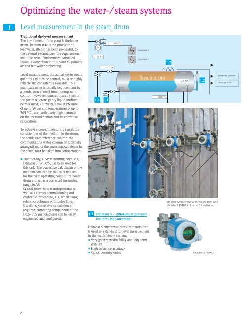
Traditional dp-level measurement<br />
The key element of <strong>the</strong> plant is <strong>the</strong> boiler<br />
drum. Its ma<strong>in</strong> task is <strong>the</strong> provision of<br />
feed<strong>water</strong>, after it has been preheated, to<br />
<strong>the</strong> external exonomizer, <strong>the</strong> superheaters<br />
and tube nests. Fur<strong>the</strong>rmore, saturated<br />
<strong>steam</strong> is withdrawn at this po<strong>in</strong>t for primary<br />
air and feed<strong>water</strong> preheat<strong>in</strong>g.<br />
M<br />
V L<br />
37.4 %<br />
61.2 bar 4<br />
399.6 °C<br />
Superheater 2<br />
Superheater 1<br />
1.2<br />
Level measurement, <strong>the</strong> actual key to <strong>steam</strong><br />
quantity and turb<strong>in</strong>e control, must be highly<br />
reliable and consistently available. This<br />
ma<strong>in</strong> parameter is usually kept constant by<br />
a combustion control (multi-component<br />
control). However, different parameters of<br />
<strong>the</strong> partly vaporous partly liquid medium to<br />
be measured, i.e. <strong>water</strong>, a boiler pressure<br />
of up to 50 bar and temperatures of up to<br />
265 °C place particularly high demands<br />
on <strong>the</strong> <strong>in</strong>strumentation and its corrective<br />
calculations.<br />
1.1 1.1<br />
Steam drum<br />
220.7 °C<br />
LZAHH<br />
-2.5 mm<br />
LZALL<br />
1.2<br />
Primary air preheater<br />
Steam gas drum<br />
To achieve a correct measur<strong>in</strong>g signal, <strong>the</strong><br />
consistencies of <strong>the</strong> medium <strong>in</strong> <strong>the</strong> drum,<br />
<strong>the</strong> condensate reference column, <strong>the</strong><br />
communicat<strong>in</strong>g <strong>water</strong> column (if externally<br />
arranged) and of <strong>the</strong> superimposed <strong>steam</strong> <strong>in</strong><br />
<strong>the</strong> drum must be taken <strong>in</strong>to consideration.<br />
• Traditionally, a P measur<strong>in</strong>g po<strong>in</strong>t, e.g.<br />
Deltabar S PMD75, has been used for<br />
this task. The corrective calculation of <strong>the</strong><br />
medium data can be statically realized<br />
for <strong>the</strong> ma<strong>in</strong> operat<strong>in</strong>g po<strong>in</strong>t of <strong>the</strong> boiler<br />
drum and set as a corrected measur<strong>in</strong>g<br />
range <strong>in</strong> P.<br />
Special know-how is <strong>in</strong>dispensable as<br />
well as a correct commission<strong>in</strong>g and<br />
calibration procedure, e.g. when fill<strong>in</strong>g<br />
reference columns or impulse l<strong>in</strong>es.<br />
If a slid<strong>in</strong>g corrective calculation is<br />
required, correct<strong>in</strong>g components of <strong>the</strong><br />
DCS/PCS manufacturer can be easily<br />
eng<strong>in</strong>eered and configured.<br />
1.1 Deltabar S – differential pressure<br />
for level measurement<br />
Deltabar S differential pressure transmitter<br />
is used as a standard for level measurement<br />
<strong>in</strong> <strong>the</strong> <strong>water</strong>/<strong>steam</strong> <strong>system</strong>.<br />
• Very good reproducibility and long-term<br />
stability<br />
• High reference accuracy<br />
• Quick commission<strong>in</strong>g<br />
dp-level measurement of <strong>the</strong> <strong>steam</strong> drum with<br />
Deltabar S PMD75 (2 out of 3 <strong>in</strong>stallation)<br />
Deltabar S PMD75
7<br />
Innovation: Higher plant availability<br />
with guided radar measurement<br />
As an alternative to differential pressure,<br />
levels can be determ<strong>in</strong>ed by Levelflex M<br />
FMP45 guided radar measurement.<br />
The <strong>in</strong>strument may be <strong>in</strong>stalled directly<br />
from <strong>the</strong> top us<strong>in</strong>g a coaxial tube <strong>in</strong> <strong>the</strong><br />
boiler drum or as a bypass variant next<br />
to exist<strong>in</strong>g local <strong>water</strong> reflex displays. In<br />
this application, Levelflex M FMP45 with<br />
EN12952-11/12953-9 approval is used as<br />
high level and low level limit.<br />
To complete <strong>the</strong> <strong>in</strong>stallation, <strong>the</strong> respective<br />
bypass as well as <strong>the</strong> high pressure tensile<br />
bolts/screws and serrated gaskets can also<br />
be supplied for Levelflex M FMP45.<br />
The gas phase compensation was particularly<br />
developed for <strong>the</strong>se special measurements,<br />
<strong>in</strong> which <strong>steam</strong> phases occur, to<br />
compensate <strong>the</strong> time-of-flight shift <strong>in</strong> <strong>steam</strong><br />
phases.<br />
A def<strong>in</strong>ed reference section at <strong>the</strong> probe<br />
comb<strong>in</strong>ed with an electronic software algorithm<br />
corrects <strong>the</strong> level value automatically<br />
and cont<strong>in</strong>ually thus offer<strong>in</strong>g correct and<br />
safe measurement.<br />
Fur<strong>the</strong>rmore, purg<strong>in</strong>g and fill<strong>in</strong>g of<br />
differential pressure pipes after stoppages is<br />
a th<strong>in</strong>g of <strong>the</strong> past.<br />
Level measurement <strong>in</strong> <strong>the</strong> <strong>steam</strong> drum with Levelflex M<br />
FMP45 (2 out of 3 <strong>in</strong>stallation) Level <strong>steam</strong> drum<br />
1.2 Levelflex M – guided microwave<br />
level measurement<br />
Levelflex provides level measurement of<br />
condensed <strong>steam</strong> <strong>in</strong> front of <strong>the</strong> turb<strong>in</strong>e<br />
<strong>in</strong> <strong>the</strong> ma<strong>in</strong> condenser (hotwell), as well<br />
as level measurement at <strong>the</strong> low pressure<br />
preheater, feed<strong>water</strong> tank, high pressure<br />
preheater and boiler drum. Levelflex<br />
provides cyclic automatic gas phase<br />
compensation, <strong>the</strong> ideal solution for precise<br />
level measurement <strong>in</strong> all <strong>steam</strong> applications.<br />
Levelflex is <strong>in</strong>dependent of:<br />
Visual <strong>steam</strong> drum level control through a sight glass<br />
• Density fluctuations<br />
• Chang<strong>in</strong>g dielectric numbers<br />
• Gas cover<strong>in</strong>g of <strong>steam</strong><br />
• Pressure and temperature changes<br />
• Vacuum (e.g. <strong>in</strong> ma<strong>in</strong> condenser hotwell)<br />
This results <strong>in</strong> a better solution than<br />
differential pressure for level measurement,<br />
provid<strong>in</strong>g:<br />
• More reliable measurement<br />
• Increased safety<br />
• Easier <strong>in</strong>stallation<br />
Levelflex M FMP45 as<br />
rod version up to 280 °C<br />
Levelflex M FMP45 as coax<br />
version up to 400 °C<br />
Levelflex is ideal as a displacer replacer.<br />
It has no mechanical mov<strong>in</strong>g parts and,<br />
<strong>the</strong>refore, no wear and tear. Levelflex is<br />
suitable for pressures up to 400 bar and<br />
temperatures up to 400 °C.
8<br />
1<br />
Level measurement <strong>in</strong>novation us<strong>in</strong>g guided radar<br />
The boiler feed<strong>water</strong> circulates with<strong>in</strong><br />
<strong>the</strong> <strong>water</strong>/<strong>steam</strong> circuit. This is <strong>the</strong> ma<strong>in</strong><br />
component <strong>in</strong> <strong>the</strong> power plant. After<br />
<strong>the</strong> <strong>steam</strong> has condensed <strong>in</strong> <strong>the</strong> ma<strong>in</strong><br />
condenser, pumps convey <strong>the</strong> feed<strong>water</strong><br />
through subsequent low and high pressure<br />
heaters <strong>in</strong>to <strong>the</strong> boiler. When it arrives at<br />
<strong>the</strong> boiler, <strong>the</strong> feed<strong>water</strong> is vaporized to<br />
saturated <strong>steam</strong> under high pressures (up<br />
to 110 bar) and high temperatures (up to<br />
318 °C). Pass<strong>in</strong>g through several levels<br />
of superheater, <strong>the</strong> <strong>steam</strong> is <strong>the</strong>n supplied<br />
to <strong>the</strong> turb<strong>in</strong>e to drive <strong>the</strong> generator.<br />
Condensation <strong>in</strong> <strong>the</strong> ma<strong>in</strong> condenser beg<strong>in</strong>s<br />
aga<strong>in</strong> and <strong>the</strong> entire procedure is repeated.<br />
Steam<br />
drum<br />
1.2<br />
Preheater<br />
Intermediate heater<br />
Superheater<br />
Vaporizer<br />
furnace<br />
To flue gas clean<strong>in</strong>g<br />
Boiler<br />
1.2<br />
Ma<strong>in</strong> condenser<br />
(hotwell)<br />
Steam turb<strong>in</strong>e<br />
Generator<br />
Monitor<strong>in</strong>g levels <strong>in</strong> <strong>the</strong> hotwell, low and<br />
high pressure preheater, feed<strong>water</strong> tank and<br />
boiler drum are of great importance for safe<br />
operation of <strong>the</strong> circuit.<br />
1.2<br />
High pressure<br />
preheater<br />
1.2<br />
Boiler feed pump<br />
Feed<strong>water</strong><br />
tank<br />
1.2<br />
Low pressure<br />
preheater<br />
Condensate<br />
pump<br />
Condensate<br />
Additional condensate<br />
from full<br />
desal<strong>in</strong>ation<br />
Hotwell (ma<strong>in</strong> condenser) Low pressure preheater Feed<strong>water</strong> tank<br />
High pressure preheater
9<br />
Pressure and temperature measurement <strong>in</strong> <strong>water</strong>-/<strong>steam</strong> <strong>system</strong>s<br />
2<br />
Overheated <strong>steam</strong> from <strong>the</strong> superheaters of<br />
<strong>the</strong> boiler enters <strong>the</strong> <strong>steam</strong> distributors. This<br />
<strong>steam</strong> is fed to different consumers from <strong>the</strong><br />
distribution station, e.g. turb<strong>in</strong>e, feed<strong>water</strong><br />
heater (degasser), process <strong>steam</strong> for<br />
chemical or pharmaceutical plants, warm<br />
<strong>water</strong> heat exchanger for utility-supplied<br />
heat, etc. In order to serve all processes, <strong>the</strong><br />
<strong>steam</strong> pressure has to be reduced to three<br />
levels:<br />
• High pressure <strong>steam</strong> 49 bar<br />
• Medium pressure <strong>steam</strong> 8.2 bar<br />
• Low pressure <strong>steam</strong> 1.7 bar<br />
A selection of <strong>in</strong>struments which measure<br />
this process with <strong>the</strong> highest degree of<br />
accuracy is:<br />
0.0 %<br />
8.4 bar<br />
HP Collector<br />
48.9 bar 401.0 °C<br />
V<br />
8.2 bar R<br />
V<br />
200.0 °C A<br />
178.6 °C<br />
178.7 °C<br />
A<br />
MP Collector<br />
0.1 % 12.4 t/h<br />
8.4 bar<br />
177.8 °C<br />
200.0 °C A<br />
178.0 °C<br />
178.0 °C<br />
0.2 %<br />
0.0 % 0.1 %<br />
V<br />
49.0 bar A<br />
140.0 °C A<br />
131.6 °C<br />
132.6 °C<br />
1.7 bar R<br />
LP Collector<br />
1.9 bar 1.9 bar<br />
0.0 %<br />
2.2 141.0 °C A 2.2<br />
132.5 °C<br />
2.1<br />
132.5 °C<br />
1.9 bar A<br />
132.2 °C<br />
2.1 Cerabar S<br />
• High pressure impact resistance <strong>in</strong> <strong>the</strong><br />
<strong>water</strong>-<strong>steam</strong> circuit<br />
• Fast commission<strong>in</strong>g via Quick Set up<br />
menu<br />
• Unique safety concept for your process<br />
application<br />
Cerabar S<br />
2.2 Omnigrad TC15 and TC88<br />
• Predom<strong>in</strong>ant use of D4 or D5 solid<br />
protect<strong>in</strong>g pipes<br />
• Preferred materials<br />
- 16Mo3/1.5415<br />
- 13CrMo4-5/1.7335<br />
• HART ® , head or DIN rail transmitter<br />
Redundant pressure monitor<strong>in</strong>g at <strong>the</strong> high and medium<br />
pressure distributor and redundant temperature monitor<strong>in</strong>g<br />
<strong>in</strong> <strong>the</strong> ma<strong>in</strong> pressure pipe by TC15 and <strong>the</strong> RIT261 display.<br />
The complete measur<strong>in</strong>g po<strong>in</strong>t <strong>in</strong>cludes <strong>the</strong><br />
<strong>the</strong>rmometer and <strong>the</strong> option of iTemp head,<br />
rail or field transmitters.<br />
TC15
10<br />
3<br />
Temperature measurement <strong>in</strong> <strong>the</strong> boiler<br />
The waste conveyed to <strong>the</strong> reciprocat<strong>in</strong>g grate is k<strong>in</strong>dled while<br />
apply<strong>in</strong>g primary and secondary air which also <strong>in</strong>fluences and<br />
controls <strong>the</strong> <strong>in</strong>c<strong>in</strong>eration. Temperature measurement <strong>in</strong> <strong>the</strong><br />
combustion chamber contributes decisively to <strong>the</strong> reduction of<br />
emissions and pollutants.<br />
Temperature measurement arranged directly <strong>in</strong> <strong>the</strong> lateral boiler<br />
walls at different levels or sensors located <strong>in</strong> <strong>the</strong> burn-up zone as<br />
well as <strong>in</strong> <strong>the</strong> passage of fur<strong>the</strong>r boiler flues provide <strong>in</strong>formation on<br />
<strong>the</strong> combustion temperature.<br />
The length and <strong>the</strong> material of <strong>the</strong> protect<strong>in</strong>g pipes as well as <strong>the</strong><br />
mechanical and chemical stra<strong>in</strong> are decisive for <strong>the</strong> corrosion and<br />
useful life of <strong>the</strong> <strong>the</strong>rmocouples. The aggressiveness of <strong>the</strong> flue gas<br />
must not be dismissed ei<strong>the</strong>r.<br />
Vessel ceil<strong>in</strong>g Superheater Electrostatic precipitator<br />
LAH<br />
LAH<br />
12392 Nm³/h<br />
5.8 mbar<br />
580.2 °C<br />
522.1 °C<br />
208.1 °C<br />
160.4 °C<br />
PSAL<br />
The follow<strong>in</strong>g materials are predom<strong>in</strong>antly used <strong>in</strong> furnaces:<br />
• Burn-up zones:<br />
Predom<strong>in</strong>antly 1.4762 / AISI446 or alternatively 1.4841 /<br />
AISI310, Type K respectively. The length of <strong>the</strong> <strong>the</strong>rmocouples<br />
is determ<strong>in</strong>ed by <strong>the</strong> l<strong>in</strong><strong>in</strong>g thickness and considerations such as<br />
avoidance of mechanical damage by slag or similar materials.<br />
• Boiler walls adjacent to <strong>the</strong> grate:<br />
S<strong>in</strong>ce <strong>the</strong> <strong>in</strong>stallation is mostly realized with a slight <strong>in</strong>cl<strong>in</strong>ation<br />
<strong>the</strong> protect<strong>in</strong>g pipes may bend downwards. The vic<strong>in</strong>ity to<br />
auxiliary burners and liquid <strong>in</strong>jections might have a negative<br />
<strong>in</strong>fluence <strong>in</strong> this situation.<br />
• Boiler combustion chamber ceil<strong>in</strong>g:<br />
S<strong>in</strong>ce <strong>the</strong> <strong>the</strong>rmocouples are directly mounted <strong>in</strong> <strong>the</strong> flue gas flow<br />
we recommend <strong>the</strong> use of a protective pipe of 1.4876 / Incoloy<br />
800HT with a solidly designed top or alternatively 1.4767 /<br />
Kanthal AF ® .<br />
• Superheater and economizer:<br />
The flue gases have now released <strong>the</strong>ir high temperatures to <strong>the</strong><br />
tube nests and o<strong>the</strong>r components <strong>in</strong>side of <strong>the</strong> <strong>steam</strong> generator.<br />
Thermocouples with protect<strong>in</strong>g pipes of 1.4762 / AISI446 are<br />
used at this po<strong>in</strong>t.<br />
Reciprocat<strong>in</strong>g grate<br />
Four-pass <strong>steam</strong> generator and electrostatic precipitator<br />
3<br />
Omnigrad S TAF16<br />
Temperature measurement at <strong>the</strong> superheater, horizontal flue<br />
Thermocouple with a protect<strong>in</strong>g tube of metal<br />
• Customized immersion length<br />
• Exchangeable measur<strong>in</strong>g <strong>in</strong>sert<br />
• Internal ceramic protective sheaths<br />
• Thermocouples with different<br />
diameters<br />
• 2-wire transmitter PC-programmable<br />
(4...20 mA), HART ® -, PROFIBUS ® - and<br />
FOUNDATION Fieldbus protocol<br />
• Double sens<strong>in</strong>g element<br />
• Various materials<br />
TAF16<br />
Temperature measurement on <strong>the</strong> boiler ceil<strong>in</strong>g
11<br />
Temperature measurement eng<strong>in</strong>eer<strong>in</strong>g<br />
Graphic configurator for temperature<br />
Today, <strong>the</strong> crucial factor of success is cost optimiz<strong>in</strong>g across <strong>the</strong><br />
whole life cycle of a plant. The eng<strong>in</strong>eer<strong>in</strong>g costs for a temperature<br />
measur<strong>in</strong>g po<strong>in</strong>t are frequently higher than <strong>the</strong> purchas<strong>in</strong>g costs of<br />
<strong>the</strong> product itself and eng<strong>in</strong>eer<strong>in</strong>g, commission<strong>in</strong>g and ma<strong>in</strong>tenance<br />
costs toge<strong>the</strong>r might amount to three times <strong>the</strong> purchas<strong>in</strong>g costs.<br />
For this reason, <strong>Endress+Hauser</strong> has developed <strong>the</strong> graphic<br />
configurator toge<strong>the</strong>r with its customers. The same supports<br />
eng<strong>in</strong>eer<strong>in</strong>g <strong>in</strong> particular with user-friendly navigation. It is thus a<br />
useful aid, from siz<strong>in</strong>g, to <strong>the</strong> operation of a temperature measur<strong>in</strong>g<br />
po<strong>in</strong>t.<br />
1 Safe siz<strong>in</strong>g of a temperature measur<strong>in</strong>g po<strong>in</strong>t with graphic trac<strong>in</strong>g<br />
and <strong>in</strong>tegrated calculation modules<br />
2 Fur<strong>the</strong>r <strong>in</strong>formation per click:<br />
Learn More area,<br />
Knowledge data base,<br />
Product sheet,<br />
Installation <strong>in</strong>struction,<br />
Technical documentation,<br />
Certificates,<br />
Spare part track<strong>in</strong>g tool <strong>in</strong>clud<strong>in</strong>g spare part list<br />
1<br />
The graphic configurator is part of <strong>the</strong> <strong>Endress+Hauser</strong><br />
Applicator as described on page 22.<br />
2<br />
View of <strong>the</strong> burn-up zone / grate
12<br />
4<br />
Deltatop dp-flow measurement <strong>system</strong> <strong>in</strong> <strong>steam</strong>, <strong>water</strong> and air<br />
Differential pressure flow devices - proven <strong>in</strong> practice. The way to<br />
avoid legal disputes on <strong>steam</strong> measurement.<br />
The ISO 5167 standard details <strong>the</strong> design and volume calculations for<br />
orifice plates, venturi tubes and nozzles. This gives significant advantages<br />
over o<strong>the</strong>r dp types (such as pitot type devices) where no specific standard<br />
exists. It is important <strong>in</strong> contractual or legal agreements to have a common<br />
calculation basis to avoid disputes about <strong>the</strong> volume measured.<br />
As an example, it is possible that a new power plant does not produce <strong>the</strong><br />
<strong>the</strong>rmal efficiency specified <strong>in</strong> <strong>the</strong> contract. The boiler supplier and <strong>the</strong><br />
turb<strong>in</strong>e manufacturer might disagree about <strong>the</strong> amount of <strong>steam</strong> actually<br />
supplied to <strong>the</strong> turb<strong>in</strong>e. The use of an agreed standard and a meter of fixed<br />
design ensures that third party experts can easily validate <strong>the</strong> meter, <strong>the</strong><br />
<strong>in</strong>stallation and <strong>the</strong> design calculations for <strong>the</strong> <strong>steam</strong> volume. This will<br />
elim<strong>in</strong>ate any potential dispute regard<strong>in</strong>g <strong>the</strong> energy conta<strong>in</strong>ed <strong>in</strong> <strong>the</strong> <strong>steam</strong><br />
flow so that <strong>the</strong>rmal efficiency can be accurately quantified.<br />
S<strong>in</strong>ce <strong>the</strong> primary element has to be eng<strong>in</strong>eered to specific customer or<br />
project requirements and sized correctly to provide <strong>the</strong> required meter<strong>in</strong>g<br />
accuracy laid down <strong>in</strong> ISO 5167, <strong>the</strong> follow<strong>in</strong>g <strong>in</strong>formation must be<br />
supplied:<br />
• Mass flow or volume flow range<br />
• Type of primary element preferred<br />
• Range of differential pressures required<br />
• Acceptable maximum permanent pressure loss<br />
• Nom<strong>in</strong>al pipe diameter<br />
• Operat<strong>in</strong>g temperature<br />
• Operat<strong>in</strong>g pressure<br />
• Standard base conditions used for reference calculations<br />
The choice of <strong>the</strong> primary element may be important if permanent pressure<br />
loss is an issue or is limited by process requirements. Reference texts show<br />
<strong>the</strong> permanent pressure drop as a function of <strong>the</strong> differential generated as:<br />
• Long pattern venturi tube 10...15 %<br />
• Short pattern venturi tube 10...20 %<br />
• Venturi nozzle 10...20 %<br />
• Nozzle 35...60 %<br />
• Orifice plates 35...70 %<br />
It is not just <strong>the</strong> primary element selection that is important. The <strong>in</strong>clusion<br />
of condensation chambers, valve manifolds, impulse l<strong>in</strong>e length and<br />
<strong>the</strong> location of pressure and temperature sensors is also important <strong>in</strong><br />
determ<strong>in</strong><strong>in</strong>g <strong>the</strong> overall <strong>system</strong> uncerta<strong>in</strong>ty as well as assur<strong>in</strong>g a reliable and<br />
safe measurement <strong>system</strong>.<br />
HP superheated <strong>steam</strong> <strong>in</strong>to<br />
turb<strong>in</strong>e<br />
Typical dp-flow applications<br />
Recommended primary elements<br />
Venturi tube/<br />
venturi nozzle<br />
➜<br />
For lowest pressure loss,<br />
meets ISO 5167 requirements<br />
Deltatop - dp flow measurement of secondary air with venturi tube long<br />
LP saturated <strong>steam</strong>/<br />
condensate return<br />
Primary- and secondary<br />
air flow<br />
Orifice plate ➜ Common standard,<br />
meets ISO 5167 requirements<br />
ISA or venturi nozzle ➜ Excellent long term stability,<br />
meets ISO 5167 requirements<br />
Vortex (Prowirl 73) ➜ Calibrated, easiest and cost<br />
effective solution up to 6<br />
Venturi tube ➜ For lowest pressure loss,<br />
reduces energy,<br />
meets ISO 5167 requirements<br />
In case ISO 5167 requirements are not important, pitot tubes can be <strong>in</strong>stalled <strong>in</strong> all mentioned<br />
applications as a cost effective solution for lowest possible pressure loss.<br />
Deltabar S dp-flow transmitter <strong>in</strong>stalled for convenient operation
13<br />
Typical cost sav<strong>in</strong>g case study*<br />
What are <strong>the</strong> sav<strong>in</strong>gs by us<strong>in</strong>g a venturi tube <strong>in</strong>stead of an orifice plate<br />
meter<strong>in</strong>g <strong>the</strong> <strong>steam</strong> <strong>in</strong>to <strong>the</strong> turb<strong>in</strong>e<br />
Steam parameters: 40 bar abs., 400 °C, 100 t/h<br />
Condensation turb<strong>in</strong>e with exhaust pressure 0.05 bar abs.<br />
Power generation: 21.25 MW<br />
Annual runtime 8.000 h<br />
Revenue per MWh produced: 100 €**<br />
Pressure loss of venturi tube = 0.12 bar<br />
Pressure loss of orifice plate = 1.2 bar<br />
Us<strong>in</strong>g a venturi tube <strong>in</strong>stead of an orifice plate <strong>in</strong>creases <strong>the</strong> power<br />
generation output from 21.19 MW to 21.25 MW due to <strong>the</strong> lower<br />
pressure loss at <strong>the</strong> meter<strong>in</strong>g po<strong>in</strong>t.<br />
This <strong>in</strong>creases <strong>the</strong> annual energy production by 543 MWh and leads to<br />
an <strong>in</strong>crease of revenue <strong>in</strong> excess of 54´000 € per year. The additional<br />
revenue is by far higher than <strong>the</strong> price adder of a venturi tube over an<br />
orifice plate.<br />
* Average figures at an <strong>in</strong>c<strong>in</strong>eration power plant<br />
** common local €uro zone price estimation<br />
Operat<strong>in</strong>g <strong>in</strong>structions for<br />
5-valve manifold<br />
Deltatop - <strong>steam</strong> flow measurement with Deltabar S<br />
and annular chamber orifice (49 bar/400 °C)<br />
Venturi nozzle with condensate pot<br />
and shut-off valves<br />
Deltabar S<br />
4 Deltabar S – <strong>the</strong> heart of any dp-flow<br />
measur<strong>in</strong>g <strong>system</strong><br />
• Clear on-site programm<strong>in</strong>g with display<br />
• Easy and fast commission<strong>in</strong>g via Quick Setup menu<br />
• The HistoROM memory module for fast recommission<strong>in</strong>g<br />
<strong>in</strong> case <strong>the</strong> transmitter needs to be replaced<br />
• S<strong>in</strong>gle side overload resistance of 420 bar (630 bar for<br />
both sides) provides unsurpassed process safety<br />
Our service:<br />
www.applicator.com gives you free of charge selection and siz<strong>in</strong>g of your flow<br />
measur<strong>in</strong>g <strong>system</strong> as per ISO 5167 standards.<br />
Fur<strong>the</strong>rmore, <strong>the</strong> dp-flow competence team at <strong>Endress+Hauser</strong> ensures<br />
that each custom-made Deltatop dp-flow solution fits correctly. This makes<br />
<strong>Endress+Hauser</strong> <strong>the</strong> right partner for dp-flow applications.
14<br />
5<br />
Liquid analyzer <strong>in</strong> feed<strong>water</strong><br />
The feed<strong>water</strong> of a <strong>steam</strong> generator must<br />
meet certa<strong>in</strong> requirements. It must be<br />
free of hardness which would cause <strong>the</strong><br />
formation of stones and sludge (scale) <strong>in</strong><br />
<strong>the</strong> boiler. The formation of scale on <strong>the</strong><br />
walls of <strong>the</strong> <strong>steam</strong> generator <strong>in</strong>creases <strong>the</strong><br />
sheet metal temperature thus impair<strong>in</strong>g <strong>the</strong><br />
stability of <strong>the</strong> boiler sheets.<br />
Preheater<br />
Intermediate heater<br />
To flue gas clean<strong>in</strong>g<br />
Boiler<br />
pH<br />
Conductivity<br />
Oxygen<br />
Steam turb<strong>in</strong>e<br />
Dissolved gases, e.g. carbonic acid and<br />
oxygen, as well as free acids are also not<br />
permitted <strong>in</strong> <strong>the</strong> <strong>water</strong>. They would cause<br />
corrosion of <strong>the</strong> boiler sheets and pipes.<br />
F<strong>in</strong>ally, <strong>the</strong> <strong>water</strong> must be free of mechanic<br />
contam<strong>in</strong>ation and colloidally dissolved<br />
substances like oils and greases to avoid<br />
foam<strong>in</strong>g of <strong>the</strong> boiler content.<br />
pH<br />
Conductivity<br />
Oxygen<br />
Steam<br />
drum<br />
High pressure<br />
preheater<br />
Superheater<br />
Vaporizer<br />
furnace<br />
Boiler feed pump<br />
Feed<strong>water</strong><br />
tank<br />
Low pressure<br />
preheater<br />
Condensate<br />
pump<br />
Condensate<br />
pH<br />
Conductivity<br />
Oxygen<br />
Generator<br />
Additional condensate<br />
from full<br />
desal<strong>in</strong>ation<br />
5.1<br />
Conductivity sensor CLS15D<br />
5.2<br />
pH-sensor CPS41D<br />
Why is conductivity measured <strong>in</strong> <strong>the</strong><br />
<strong>water</strong>-<strong>steam</strong> circulation <strong>system</strong><br />
The conductivity measurement detects<br />
<strong>the</strong> feed<strong>water</strong> concentration of ions<br />
and measures it <strong>in</strong> S/cm. A change <strong>in</strong><br />
conductivity dur<strong>in</strong>g operation <strong>in</strong>dicates<br />
impurity <strong>in</strong> feed<strong>water</strong> quality.<br />
Why is <strong>the</strong> pH-value measured <strong>in</strong> <strong>the</strong><br />
<strong>water</strong>-<strong>steam</strong> circulation <strong>system</strong><br />
The pH-value, i.e. <strong>the</strong> concentration of<br />
hydrogen ions, shows whe<strong>the</strong>r a solution<br />
is acid, neutral or alkal<strong>in</strong>e. The pH-value<br />
measurement thus monitors <strong>the</strong> feed<strong>water</strong><br />
to protect <strong>the</strong> pipes aga<strong>in</strong>st corrosion and<br />
build-up.<br />
Conductivity sensor CLS15D<br />
pH-sensor CPS41D<br />
5.3<br />
Oxygen sensor COS21D<br />
Why is O 2<br />
measured <strong>in</strong> <strong>the</strong> <strong>water</strong><strong>steam</strong><br />
circulation <strong>system</strong><br />
The feed<strong>water</strong> oxygen concentration is<br />
stated <strong>in</strong> mg/l. High oxygen concentrations<br />
promote corrosion of <strong>the</strong> steel pipes by<br />
electrochemical processes and must be<br />
cont<strong>in</strong>ually monitored.<br />
Oxygen sensor COS21D
15<br />
5.4 Liquil<strong>in</strong>e M<br />
Liquil<strong>in</strong>e is a modular two-wire transmitter for pH,<br />
conductivity and oxygen measurement <strong>in</strong> <strong>water</strong><strong>steam</strong><br />
circulation <strong>system</strong>s. Variants are available to<br />
connect Liquil<strong>in</strong>e to bus <strong>system</strong>s like FOUNDATION<br />
Fieldbus, PROFIBUS ® and HART ® protocol.<br />
• Easy commission<strong>in</strong>g with Quick Setup and Navigator<br />
button<br />
• Predictive ma<strong>in</strong>tenance <strong>system</strong> recognizes when a<br />
sensor has to be cleaned, calibrated or replaced<br />
• Comb<strong>in</strong>ed with Memosens cable breakage is<br />
<strong>in</strong>dicated on <strong>the</strong> display<br />
• User-guided commission<strong>in</strong>g, graphic display and pla<strong>in</strong><br />
text menue<br />
• Modular concept: Sensor module exchangeable.<br />
Liquil<strong>in</strong>e CM42<br />
5.5<br />
Digital sensor for pH-value, O 2<br />
and<br />
conductivity: Memosens<br />
Memosens, <strong>the</strong> first digital sensor worldwide, may be<br />
precalibrated at <strong>the</strong> laboratory. An <strong>in</strong>ductive plug-<strong>in</strong><br />
connection with bidirectional signal and energy transfer<br />
ensures perfect transmission of digital signals between<br />
sensor and transmitter. The calibration values are<br />
stored <strong>in</strong> <strong>the</strong> sensor. The <strong>in</strong>ductive plug-<strong>in</strong> connection<br />
is free of metal and excludes all impairments as <strong>the</strong>y<br />
might occur <strong>in</strong> conventional connections which are not<br />
without contact:<br />
• Safe, non-contact measurement also <strong>in</strong> case of<br />
humidity<br />
• Process data is stored directly <strong>in</strong> <strong>the</strong> sensor<br />
• Measured data cannot be falsified<br />
• Calibration possible at <strong>the</strong> laboratory<br />
• Significantly shorter downtimes of <strong>the</strong> measur<strong>in</strong>g<br />
po<strong>in</strong>t<br />
• Easier <strong>in</strong>stallation without special cable<br />
• Predictive diagnostics directly <strong>in</strong> <strong>the</strong> sensor<br />
<strong>system</strong><br />
Memosens technology
16<br />
<strong>Optimiz<strong>in</strong>g</strong> fur<strong>the</strong>r applications<br />
6<br />
Level and flow measurement at <strong>the</strong> scrubber<br />
Flue gas is washed <strong>in</strong> several stages <strong>in</strong> <strong>the</strong> scrubber. A noncontact<br />
<strong>system</strong> is recommended to measure <strong>the</strong> <strong>water</strong><br />
circulation of <strong>the</strong> scrubber sump and <strong>the</strong> r<strong>in</strong>g jet stage s<strong>in</strong>ce <strong>the</strong><br />
medium conta<strong>in</strong>s acid flue gas components and a dry content<br />
of 0.1-2 %. The pH-value of <strong>the</strong> scrubber sump usually ranges<br />
between pH 0.8-1.5. The <strong>in</strong>stallation of ultrasonic sensors<br />
is recommended with only one cross brace because of this<br />
dry content. Internal rubber l<strong>in</strong><strong>in</strong>g of a steel pipe also has a<br />
favorable effect on <strong>the</strong> strength of <strong>the</strong> signal if only one cross<br />
brace is used > ~70 dB. The response time of this measurement<br />
directly <strong>in</strong>fluences scrubber protection, i.e. after start<strong>in</strong>g<br />
<strong>the</strong> quench pumps a flow of more than 100 m3/h must be<br />
achieved with<strong>in</strong> less that 10 sec. - o<strong>the</strong>rwise <strong>the</strong> scrubber has<br />
to be restarted.<br />
54.9 °C<br />
Flue gas wash<strong>in</strong>g level 3<br />
70.5 %<br />
30.0 mbar A<br />
30.1 mbar<br />
7.0 pH A<br />
6.1<br />
3.0 bar<br />
7.1 pH<br />
59.8 %<br />
6.2<br />
Flue gas wash<strong>in</strong>g level 2<br />
2.0 bar<br />
R<strong>in</strong>g jet stage<br />
59.5 %<br />
6.2<br />
Flue gas wash<strong>in</strong>g level 1<br />
57.0 %<br />
6.2<br />
Quench <strong>water</strong> flow measurement <strong>in</strong> a pipe l<strong>in</strong>ed with rubber<br />
6.1<br />
Prosonic Flow Clamp On 93W – ultrasonic flow meter<br />
Prosonic Flow is an ultrasonic measur<strong>in</strong>g <strong>in</strong>strument<br />
<strong>in</strong>stalled directly on pipel<strong>in</strong>es via detect<strong>in</strong>g sensors. The<br />
transmitter, which is mounted separately, completes <strong>the</strong><br />
Prosonic Flow measur<strong>in</strong>g <strong>system</strong>.<br />
• External <strong>in</strong>stallation allow<strong>in</strong>g easy retrofit with no<br />
<strong>in</strong>trusion <strong>in</strong>to <strong>the</strong> pipe<br />
• Ma<strong>in</strong>tenance-free with no mov<strong>in</strong>g parts<br />
• No obstructions <strong>in</strong> <strong>the</strong> pipel<strong>in</strong>e and no pressure loss<br />
• Economical alternative for large diameters up to<br />
4000 mm<br />
• Portable ultrasonic transmitter for temporary meter<strong>in</strong>g<br />
Prosonic Flow Clamp On 93W
17<br />
To prevent <strong>the</strong> flue gases from flow<strong>in</strong>g unwashed<br />
through <strong>the</strong> scrubber, several stages<br />
with<strong>in</strong> <strong>the</strong> scrubber are filled with <strong>water</strong> and<br />
<strong>the</strong>ir levels are controlled.<br />
The acid stage or sump is located at <strong>the</strong><br />
scrubber <strong>in</strong>let, <strong>the</strong>n up to two packed bed<br />
stages follow, <strong>in</strong> which <strong>the</strong> flue gas is offered<br />
a large quantity of pack<strong>in</strong>g material, wetted<br />
by scrubb<strong>in</strong>g <strong>water</strong>. The solids stay on <strong>the</strong><br />
pack<strong>in</strong>g material, are washed out and moved<br />
downwards.<br />
To scrub <strong>the</strong> rema<strong>in</strong><strong>in</strong>g suspended solids, <strong>the</strong><br />
flue gas must pass spray<strong>in</strong>g nozzles on <strong>the</strong> r<strong>in</strong>g<br />
jet stage for <strong>the</strong> last time and is subsequently<br />
made neutral with a pH-value of 7.1.<br />
To monitor all differential pressures and gas<br />
wash<strong>in</strong>g levels, remote seal differential pressure<br />
transmitters of <strong>the</strong> FMD78 type with tantalum<br />
as wetted parts are used, partly <strong>in</strong> a redundant<br />
fashion.<br />
6.2<br />
Deltabar S FMD78<br />
• Very good reproducibility and long-term<br />
stability<br />
• High reference accuracy: up to ±0.075 %<br />
• Turn down 100:1, higher upon request<br />
• Applications for flow and differential pressure<br />
monitor<strong>in</strong>g up to SIL3, certified by TÜV SÜD<br />
accord<strong>in</strong>g to IEC 61508<br />
• Memory module HistoROM ® /M-DAT<br />
• Function controlled from <strong>the</strong> measur<strong>in</strong>g cell<br />
through to electronics<br />
Deltabar S FMD78,<br />
remote seal version